Us5683761
•
0 likes•5 views

Inventors and entrepreneurs have vocations fueled by passion. Many would have done it for free or as a hobby if it hadn’t become a profession. Mark Rosenzweig is a natural creator, driven by his passion. This fuel has led Mark to develop his ideas into viable products and innovations that he has been patenting since 2003. From an innovative filter sensor and indicator for vacuum cleaners to a basket for deep fryer and methods of cooking food products to a compact cyclonic bagless vacuum cleaner. Sometimes independently and often as part of creative teams, Mark has patented just under one hundred innovative inventions between 2003 and 2017.

Recommended
More Related Content
What's hot
Similar to Us5683761
Similar to Us5683761 (20)
More from Mark Rosenzweig
Recently uploaded
Recently uploaded (20)
Us5683761
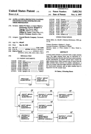
- 1. United States Patent (19) Bruce et al. 54 75 (73) 21 22 51 52 58 56 ALPHAALUMNAPROTECTIVE COATINGS FOR BOND.COATED SUBSTRATES AND THER PREPARATION Inventors: Robert W. Bruce, Loveland; Mark A. Rosenzweig, Hamilton; BangaloreA. Nagaraj, West Chester; Jon C. Schaefer, Milford, all of Ohio; William B. Connor, Clifton Park, N.Y.; David J. Wortman, Hamilton, Ohio Assignee: General Electric Company, Cincinnati, Ohio Appl. No.: 450,647 Filed: May 25, 1995 Int. C. m. C23C 16/40 U.S. Cl. .................. 427/596; 427/255.7; 427/419.2 Field ofSearch .......................... 427/255.3, 255.7, 427/419.1, 419.2, 596, 126.3, 126.1, 126.4 References Cited U.S. PATENT DOCUMENTS 3,442,686 5/1969 Jones .................... ... 117/70 4,095,003 6/1978 Weatherly etal. ....................... 427/34 4,321,311 3/1982 Strangman ....... ... 428/623 4,405,659 9/1983 Strangman ... ... 427/248.1 4,405,660 9/1983 Ulion et al... ... 457/248.1 4,414.249 11/1983 Ulion et al. .......... ... 427/248.1 4,481.237 11/1984 Bosshart et al. ..... ... 427/376.4 4,576,874 3/1986 Spengler et al. ........................ 428/623 US005683761A 11 Patent Number: 5,683,761 45 Date of Patent: Nov. 4, 1997 4,676,994 6/1987 Demaray .................................. 427A2 4,743,514 5/1988 Strangman et al. ... 428,678 4,855,603 8/1989 Lindmayer .......... ... 250/.484.1 4,880,614 11/1989 Strangman et al. ... 428/623 5,055,319 10/1991 Bunshah et al. .......................... 427/38 5,087.477 2/1992 Giggins, Jr. etal. ..................... 427/38 5,147,731 9/1992 Gilmore et al. ... ... 428/633 5,338,577 8/1994 Burdette, II ... .427.53 5,407,705 4/1995 Vakil ....... ... 427/255 5,434,008 7/1995 Felts ............ ... 428/461 5,538,796 7/1996 Schaffer et al. ........................ 428/469 OTHER PUBLICATIONS Grant, Julius, ed., Hackh's Chemical Dictionary, 1969, pp. 31-32. Primary Examiner-Kathryn L. Gorgos Assistant Examiner-Chrisman D. Carroll Attorney, Agent, or Firm-Andrew C. Hess; David L. Narciso 57 ABSTRACT Abond-coated substrateis protectedwith an alpha alumina layer. The alpha alumina layer may be deposited as a relativelythicklayerdirectlyontothebond-coatedsubstrate. In this embodiment, no further ceramic layer overlies the alpha alumina layer. Other ceramics may be mixed into the alpha alumina layer, however. In another embodiment, a layerofaceramicotherthanalphaaluminais depositedover the bond-coated substrate, and an alpha alumina layer is deposited over the ceramic layer. 18 Claims, 2 DrawingSheets alowaa a2ay 72 SaMass/26a72 Saas/e12Za 292 a A2Zawoa2A722 Slas/eava 462 23 Ayaa7soMD 2OaZaa SA/3376a772 a 2422/7. AAF177Zay22 (2a 2afaeos Zaay2 a aaaaya AZayaya ZaaaSM7 Zay276 as a 14Wad AeaAf/4. aAAM/Mya 49 Sassa7a 2aa26/7 AAY26 saf2021/2 22227 aaaaaaya 4A619M1/6 222a2Aaawe 12A.Z/WAM4
- 2. U.S. Patent Nov. 4, 1997 Sheet 1 of 2 5,683,761
- 3. 5,683,761Sheet 2 of 2Nov. 4, 1997U.S. Patent
- 4. 1. ALPHAALUMNA PROTECTIVE COATNGS FOR BOND-COATED SUBSTRATES AND THER PREPARATION BACKGROUND OF THE INVENTION Thisinvention relatesto theprotection ofsubstrates,and, more particularly, to thermal barrier coating systems for superalloys used in gas turbine engines. Inanaircraftgas turbine(jet) engine,airisdrawnintothe front of the engine, compressed by a shaft-mounted compressor,andmixedwithfuel.Themixtureisburned,and thehotexhaust gases are passedthrough a turbine mounted on the same shaft.Theflow of gas turns the turbine, which turns the shaft and provides power to the compressor. The hotexhaustgases flowfrom thebackofthe engine, driving it and the aircraftforwardly. The hotter the exhaust gases, the more efficient is the operationofthejetengine.Thereisthusanincentiveto raise the exhaust combustion gas temperature. However, the maximumtemperature ofthe combustion gasesis normally limited by the materials used to fabricatethe turbine vanes and turbine blades ofthe turbine, upon which the combus tion gases impinge when they are at their hottest tempera tures. In current engines, the turbine vanes and blades are made of nickel-based superalloys, and can operate at tem peratures ofup to 1900-2100 F. Many approaches have been usedto increase the operat ingtemperaturelimitofthe turbinebladesandvanestotheir currentlevels.The compositionandprocessingofthe mate rials themselves have been improved, andphysical cooling techniques are used. In another approach, a protective thermal barrier coating system is applied to the turbine blade or turbine vane component,which serves as asubstrate.Thethermalbarrier coating system includes a ceramic thermal barrier coating that insulates the component from the hot exhaust gas, permittingtheexhaustgastobehotterthan wouldotherwise be possible with the particular material and fabrication process ofthe component. An additional layercalled abond coatisplacedbetweenthe substrate and thethermal barrier coating to aid in adhering the ceramic thermal barrier coatingto the substrate and to protect the substrate against contact with the exhaust gases and against oxidation. In currentpractice, the ceramicthermal barrier coating is madeofzirconia(zirconiumoxide)thatisstabilizedwiththe addition of from about 6 to about 8 weight percent yttria (yttrium oxide), a material known as yttria-stabilized zirco nia or YSZ. While operable, the YSZ is relatively dense compared to many other ceramics. High density is a disadvantage, particularly for use on rotating components such as turbine blades. Moreover, there is a continuing search for ceramic materials and configurations ofthe pro tective coatingwith improved erosion andimpactresistance tothehotgas environmentandthat,in combination with the bond coat, contribute to improved performance ofthe pro tected article. SUMMARY OF THE INVENTION The present invention provides a protected article and a method forits preparation.Theprotection is provided by a coating system utilizing a ceramic overcoating layer and a bond coat between the ceramic overcoating layer and the substrate. The protective system is less dense than a con ventionalthermalbarriercoatingsystem,anditcantherefore be made thicker to provide superior thermal insulation, 5,683,761 5 10 15 20 25 30 35 45 50 55 65 2 withoutaddingweight.Theprotective coatingoftheinven tion has equivalent or superior erosion resistance and cor rosion resistance, as well as better overall oxidationprotec tion of the substrate, as compared with a conventional coating system. In accordance with one aspect of the invention, a pro tectedarticle comprises a substrate, a metallicbond coaton the substrate, and a protective coating comprising alpha alumina on the bond coat, with no further ceramic material layer over the alpha alumina coating. In one form of this embodiment, the ceramic thermal barrier coating is alpha alumina, either solely or with another ceramic or other ceramics mixed with the alpha alumina. This embodiment takesfull advantage ofthe low density ofthealpha alumina anditsprotective,erosion-resistantqualities.Alpha alumina has a lower density but higher thermal conductivity than many other ceramic materials such as yttria-stabilized Zir conia. It is therefore preferably applied as a thicker coating than the ceramic coating used in conventional thermal barrier coating systems to achieve equivalent or superior thermal protection, to achieve superior erosion resistance, impactresistance, and oxidationprotection ofthe substrate. This embodimentisparticularlyuseful whentheapplication requires a high erosion resistance ofthe coating. In another embodiment of the invention, a protected article comprises a substrate, a metallic bond coat on the substrate,atoplayerofalphaalumina,anda secondceramic material layer between the bond coat and the top layer of alphaalumina.The second ceramic materiallayercouldbe, for example, conventionalyttria-stabilizedzirconia or other ceramic. This embodiment takes advantage of the oxygen diffusion-barrier qualities ofthe alpha alumina and its ero sion and impact resistance by placing the top layer of the alpha alumina over the second ceramic material. The present invention utilizes alpha alumina as the pri marythermalbarriercoatingmaterial orasanovercoatover another ceramic in the thermal barrier coating. The alpha alumina is strongerand moreerosion resistantthan conven tional materials such as YSZ at elevated temperatures. The alpha alumina also exhibits impact resistance and fracture toughness superior to the YSZ. Alpha alumina has the additional importantadvantagethatitcan betoughenedand made less susceptible to cracking by transformation tough ening procedures. The transformation toughening is achievedbymixingotherceramics suchaszirconiawiththe alpha alumina. The alpha alumina can also be mixed with ceramicssuchas nickel oxide, magnesium oxide, chromium oxide, titanium oxide, and yttrium oxide to create spinels and graded ceramic structures. The present invention is limited to the use of alpha alumina rather than other forms of alumina. When other forms of alumina are deposited or are present, they can be expectedtoexperiencephasetransformationsduringservice to a more stable form. These phase transformations are accompanied by volume changes, which in turn can leadto wrinkling, cracking, or spalling of the ceramic coating, a major disadvantage. The invention also extends to a method for preparing the coated articles. In accordance with this aspect of the invention, a method for preparing a protected article com prises the steps of providing a substrate, applying a bond coattothesubstrate,anddepositinga layerofalphaalumina ontothebond-coated substrate. Duringthe depositionofthe alpha alumina, the bond-coated substrate is heated to a temperature ofat leastabout 1800°F, and morepreferably to a temperature ofabout2000°F,while thealpha alumina is being deposited thereon.
- 5. 5,683,761 3 This deposition technique canbeadaptedtothe structures discussed previously, as well as others. For example, the layer of alpha alumina can be deposited overlying and directly onto the bond coat with no further ceramic material layer deposited thereover. A layer of a second ceramic material can be deposited over the bond coat, and the layer of alpha alumina deposited over the layer of the second ceramic material. In another application, the layer of alpha alumina can be deposited overlying and directly onto the bond coat, and a layer of a second ceramic material depos ited overlying the layer of alpha alumina. In each case, the bond-coated substrate is heated to at least 1800. F., and preferably to 2000°F, while the alphaaluminais deposited (but not necessarily when other ceramic layers are deposited). Deposition of the alpha alumina is preferably accomplished in all cases by electron beam physical vapor deposition. The present invention provides an advance in the art of thermal barrier coating systems for protecting substrates. It is most advantageously used with nickel-base superalloys that are used in gas turbine engine applications. Other features and advantages of the present invention will be apparentfromthefollowing more detaileddescription ofthe preferred embodiment,takenin conjunctionwiththe accom panying drawings, which illustrate, by way ofexample, the principles of the invention. BRIEF DESCRIPTION OF THE DRAWTNGS FIG. 1 is a perspective view of a protected article; FIG.2(a) is a schematic sectional viewthrough thearticle ofFIG. 1,taken generally along line2-2, illustrating afirst embodimentofaprotective coatingsystem on thesurface of the article; FIG.2(b)is aschematic sectional viewthrough thearticle of FIG. 1, taken generally along line 2-2, illustrating a second embodiment of a protective coating system on the surface of the article; and FIG. 3 is a block diagram depicting three methods prac ticed according to the invention. DETALED DESCRIPTION OF THE INVENTION The protective approach of the invention can be used in conjunction with various articles. FIG. 1 depicts one such article by way of example, a component of a gas turbine engine such as a turbine blade or turbine vane. In this case the article is depicted as a turbine blade 20. The turbine blade 20 includes an airfoil 22againstwhich theflow ofhot exhaust gas is directed. The turbine blade 20 is mounted to a turbine disk (not shown) by a dovetail 24 which extends downwardly from the airfoil 22 and engages a slot on the turbinedisk.Aplatform26 extendslongitudinallyoutwardly fromthe areawheretheairfoil22isjoinedtothe dovetail 24. Anumber ofcooling channels optionallyextend through the interioroftheairfoil 22,endingin openings28inthesurface ofthe airfoil 22. Aflow ofcoolingairis directedthroughthe cooling channels,to reducethe temperature oftheairfoil22. FIGS. 20a) and 2(b) respectively illustrate two embodi ments ofa protective system 30 deposited upon the turbine blade20,whichtherebyactsas a substrate32. (Thesefigures are not drawn to scale.) The substrate32 may be formed of anyoperablematerial,butapreferredbasemetalfromwhich the article substrate is formed is a nickel-base superalloy. A preferred superalloy has a nominal composition in weight percentof13percentcobalt, 6percentchromium, 6percent 10 15 25 30 35 45 50 55 65 4 aluminum, and 3 percent rhenium, balance nickel, but other superalloys such as Rene N5 can be used. The substrate 32 may be prepared in any operable manner, and may be a polycrystal, an aligned polycrystal, or a single crystal. The protective system 30 includes a bond coat34 depos ited overlying and directly contacting the substrate 32. The bond coat34 aids in adhering the overlying structure to the substrate, both initially and during service. The bond coat desirablyhasa coefficientofthermal expansionintermediate that of the substrate and the overlying structure. The bond coat also preferably contains aluminum in an amount suf ficientto forman aluminum oxide scale over the bond coat, eitherin aninitial oxidation orduringservice.The bond coat may be of any operable composition, including, for example, an alloy of the NiCrAIY or CoCrAIY type or a platinum aluminide. The bond coat 34 is preferably from about 0.002 to about 0.004 inches thick, and is preferably deposited by low pressure plasma spray or chemical vapor deposition. Oneor morelayers ofceramicoverliesthebond coat.Two preferred embodiments of the overlying structure are illus trated in FIGS. 2(a) and 20b), respectively. Theprotective system 30 ofthe embodiment ofFIG. 2(a) includes a layer 36 of alpha alumina ceramic deposited overlying and directly contactingthe bond coat 34.There is preferably no further layer overlying the layer 36 in this embodiment. The conventional yttria-stabilized zirconia (YSZ) ceramic material is a better insulator per unit thick ness than alpha alumina, but the alpha alumina is much lighterper unitthickness thanYSZ. Stated alternatively, the alpha alumina may be made much thicker than theYSZfor an equivalent weight. The use of a thicker layer of alpha alumina rather than a thinner layer of YSZ to achieve thermal protection ofthe substrate has the advantage thatit is moreerosion resistant.Thehigherthermal conductivity of alpha alumina can be somewhat offset by depositing the layer36 by electron beamphysical vapor deposition, which leaves a degree ofporosity in the layer 36 that reduces its thermal conductivity.Thus, the layer36 of alpha alumina is preferably from about 0.002 inches to about 0.015 inches, most preferably from about 0.005 inches to about 0.010 inches, thick. Thicker and thinner layers are also operable. Additionally, alpha alumina has the advantage that it is more resistant to impact and erosion damage than YSZ. A thicklayer ofalpha alumina provides excellent impact and erosion resistance to the substrate 32. The deposited alpha alumina is compatible with the aluminum oxide scale that can be, and usually is, present at the interface between the bond coat34 and the layer36.Thealphaaluminaisresistant to diffusion of oxygen therethrough, and therefore tends to protect the substrate againstoxidation.The alphaalumina is strong and hard at elevated temperatures. Additionally, alpha alumina can be transformation tough ened by the addition of small amounts of additional con stituents mixedintothealpha alumina.Theaddition ofabout 25 percentby weight ofzirconia toalpha alumina increases its fracture toughness to about 8 ksi-root inches. Additions of other oxides to alpha alumina such as nickel oxide, magnesium oxide, titanium oxide, and yttrium oxide can also be made to the alpha alumina to create spinels and graded ceramic structures. The layer 36 must be alpha alumina, a rhombohedral form, rather than other forms of alumina such as gamma (cubic) alumina Alpha aluminaisthermodynamicallystable at elevated temperatures, even above about 2000 F., whereas other forms of alumina will transform to more
- 6. 5,683,761 5 stable forms during elevated temperature exposure. The transformation observedin otherforms ofaluminaisaccom panied by a volume change, leading to deformation, wrinkling, and/orfailureby spalling ofthe layer. Thealpha alumina form is chosen to avoid the occurrence of such transformations. In the embodiment of FIG. 2(b), which is the presently mostpreferred embodiment, a layer38 ofa secondceramic isdeposited overlyingand directly contactingthebondcoat 34. The layer 38 is formed of a ceramic other than alpha alumina, such as YSZ or cerium oxide. The layer 38 is preferably from about 0.002 inches to about 0.015 inches thick Atoplayer40ofalphaaluminais depositedoverlying and directly contacting the layer.The top layer 40 is pref erably from about 0.00025 inches to about 0.004 inches thick. This embodiment combines the good thermal insula tive properties ofYSZ or other low-conductivity ceramics with the erosion/impact resistance of alpha alumina. The alpha alumina also serves as a corrosion-resistant layer against deposits containing vanadium which are often observed in industrial and marine gas turbine engines. FIG. 3 depicts three embodiments of a method for pre paring a protected substrate. In all embodiments, the sub strate 32 is provided, numeral 50, and the bond coat 34 is appliedtothe substrate, numeral52.The substrate32andits method ofpreparation,and the bond coat34 andits method ofapplication, are as described previously. In a first embodiment, path A, the bond-coated substrate is heated to a temperature of at least about 1800° F, and most preferably to a temperature offrom about 1975° F to about 2050 F., numeral 54. A layer of alpha alumina is deposited directlyontothe bond coat34 atthistemperature, numeral 56. The layer of alpha alumina is preferably from about0.0001 inchtoabout0.005inches thick. Depositionof the alpha alumina layer is preferably accomplished by electronbeamphysicalvapordeposition (EBPVD). EBPVD ofaluminafromamoltenpooltotheheatedsubstrateresults in deposition ofthe alumina in its alpha aluminaform.The use ofEBPVD is preferred over otherapproaches to depo sition ofalumina, such as chemicalvapordeposition (CVD) foranumberofreasons. EBPVDisfasterandachievesgood coverage of the surface. EBPVD is performed in the same chamber as the deposition of the other ceramic layers, if used, and thebond coatinits preferredapplication method. Contamination due to moving the bond-coated substrate betweendepositiondevicesistherebyavoided.Additionally, EBPVDproducesadesirable segmented columnarstructure inthe depositedalphaaluminalayer,ascomparedwithother techniques which produce a flat platelet structure in the deposited alumina layer.The segmented columnar structure is preferredforits resistance to thermal cycling damage.To completetheprocessingofembodimentA,a second layerof ceramic such as YSZ is deposited over the layer ofalpha, numeral 58 The second layer of ceramic need not be, but may be, deposited at the same temperature as the alpha alumina layer. The layer of second ceramic is preferably from about 0.002 inches to about 0.015 inches thick. In the resulting structure, which is not pictured, the layer ofalphaalumina liesbetween thebond coatandthe layer of secondceramic.Sucha structurehasbeenpreviously known and is described in U.S. Pat. No. 4,880,614. However, the present approach has the advantage over the approach described in the '614 patent that the various layers are deposited inthe same deposition chambertoavoidcontami nation resulting from moving the substrate between depo sition chambers. Inasecondembodiment,path B,thesubstrate32isheated to a temperature of at least about 1800 F, and most 10 15 20 25 30 35 45 50 55 65 6 preferably to a temperature offrom about 1975° F to about 2050 F., numeral 60. The layer 36 of alpha alumina is depositeddirectlyontothebond coat34atthistemperature, numeral 62.The layer ofalpha alumina is preferably from about 0.002 inches to about 0.015 inches, most preferably from about 0.005 inches to about 0.010 inches, thick. Deposition ofthe alpha alumina layeris preferably accom plished by EBPVD. The resulting structure corresponds to that depicted in FIG. 2(a). In a third embodiment, path C, the layer 38 ofthe second ceramic is deposited, numeral 64. Deposition is by any approach suitable for the second ceramic, which is most preferablyYSZ.Thelayer38ispreferablyfromabout0.002 inches to about 0.015 inches thick. The coated substrate 32 is heated to a temperature of at least about 1800°F, and most preferably to a temperature offromabout 1975° F to about 2050°F, numeral 66. Alayer 40 ofalpha alumina is deposited directly onto the second ceramic layer 38 at this temperature, numeral 68. The layer of alpha alumina is preferablyfrom about 0.00025inches to about0.004 inches thick. Deposition of the alpha alumina layer is preferably accomplished by EBPVD. The resulting structure,corre spondstothemostpreferredstructuredepictedin FIG.2(b). The approach ofthe third embodiment has been reduced to practice. In this reduction, the substrate was Rene N5 nickel-based superalloy, and the bond coat was platinum aluminide.About 0.005 inches ofYSZwas deposited over lying and contacting the bond coat. About 0.001-0.002 inches ofalphaaluminawasdeposited overlyingtheYSZby EBPVD with the coated substrateata temperature ofabout 1850 F. The erosion resistance of this material was mea sured by blastingthe surface ofthe alpha alumina layer40 with 100 grams of alumina grit of 50 micrometer particle size carried in 25 pounds per square inch air at a flow rate of98 feetper second and at a 90 degree impactangle. The penetration depth was about 0.002 inches. By comparison, YSZ material tested by the same approach exhibited a penetrationdepth ofabout0.0034inches.Thefurnace cycle test life of the materials was about the same. This invention has been described in connection with specificembodimentsandexamples. However,thoseskilled intheartwillrecognizevarious modificationsandvariations ofwhichthe presentinvention is capable withoutdeparting from its scope as represented by the appended claims. What is claimed is: 1.A methodforpreparing a protected article, comprising the steps of: providing a substrate; applying a bond coatto the substrate; and depositing a layer of alpha alumina by electron beam physical vapor deposition onto the bond-coated substrate, the step of depositing including the step of heatingthebond-coated substrate toatemperature ofat least about 1800° F while the alpha alumina is being deposited thereon. 2.The method ofclaim 1,wherein the step of depositing includes the steps of heating the bond-coated substrate to a temperature of at east about 1800. F.; depositinga layerofalphaalumina directly onto the bond coat; and depositinga layer ofa second ceramic material overlying the layer of alpha alumina. 3. The method of claim 1, wherein the step of depositing includes the steps of heating the bond-coated substrate to a temperature of at least about 1800° F.; and
- 7. 5,683,761 7 depositingalayer ofalphaalumina directly ontothe bond coat with no further ceramic material layer deposited thereover. 4. The method of claim 1, wherein the step of depositing includes the steps of depositing a layer of a second ceramic material over the bond coat; heating the substrate, bond coat, and layer of second ceramic material to a temperature of at least about 1800° F and depositing a layer of alpha alumina over the layer ofthe second ceramic material. 5. The method ofclaim 1, wherein the step of applying a bond coat includes the step of applying a metallic bond coat to the substrate. 6. A method for preparinga protected article, comprising the steps of: providing a substrate; applying a bond coat to the substrate; providing a deposition source of alpha alumina; and depositing a layer of alpha alumina from the deposition source of alpha alumina onto the substrate, the step of depositing including the step of heating the bond coated substratetoatemperature ofatleastabout 1800° F, while the alpha alumina is being deposited thereon. 7. A method for preparing a protected article, comprising the steps of: providing a substrate; applying a bond coat to the substrate; providing a deposition source of alpha alumina; and depositing a layer of alpha alumina from the deposition source ofalpha alumina onto the substrate, the step of depositing including the step of heating the bond coatedsubstratetoatemperature ofatleastabout 1800° F, while the alpha alumina is being deposited thereon, wherein the step of depositing a layer ofalpha alumina includes the step of depositing the layer of alpha alumina from about 0.0001 inch to about 0.005 inch thick. 8. The method of claim 7, including an additional step, after the step of depositing a layer of alpha alumina, of depositing a layer ofa second ceramicoverlyingthe layer of alpha alumina. 9. The method of claim 7, including an additional step, after the step of depositing a layer ofalpha alumina, of depositing a layer ofyttria-stabilized zirconia overlyingthe layer ofalpha alumina. O 15 20 25 30 35 45 8 10. The method of claim 7, including an additional step, after the step ofapplyinga bond coatand before the step of depositing a layer of alpha alumina, of depositinga layer ofa second ceramic overlyingthe bond coat. 11.The method ofclaim 7, whereinthe stepofdepositing a layer of alpha alumina includes the step of depositing the layer of alpha alumina by electron beam physical vapor deposition. 12. The method of claim 7, wherein the step of applying a bond coat includes the step of applying a metallic bond coat to the substrate. 13.Amethodforpreparingaprotectedarticle,comprising the steps of: providing a substrate; applying a bond coat to the substrate; providing a deposition source of alpha alumina; and depositing a layer of alpha alumina from the deposition source ofalpha alumina ontothe substrate, the step of depositing including the step of heating the bond coatedsubstratetoatemperatureofatleastabout 1800° F. while the alpha alumina is being deposited thereon, wherein the step ofdepositing a layer ofalpha alumina includes the step of depositing the layer of alpha alumina from about 0.005 inch to about 0.010 inch thick. 14. The method ofclaim 13,including an additional step, after the step of depositing a layer of alpha alumina, of depositing a layer ofa second ceramic overlyingthe layer of alpha alumina. 15. The method ofclaim 13, including an additional step, afterthe step of depositing a layer ofalpha alumina, of depositing a layer of yttria-stabilized zirconia overlying the layer of alpha alumina. 16. The method ofclaim 13,including an additional step, afterthe step ofapplying a bond coatand before the step of depositing a layer of alpha alumina, of depositing a layer ofa second ceramic overlyingthebond Coat. 17. The method of claim 13, wherein the step of depos iting a layer of alpha alumina includes the step of depositing the layer of alpha alumina by electron beam physical vapor deposition. 18.The method ofclaim 13, wherein the stepofapplying a bond coatincludes the step of applying a metallic bond coat to the substrate.