SlideShare a Scribd company logo
1 of 13
Download to read offline
(12) United States Patent
US009107539B2
(10) Patent No.: US 9,107,539 B2
Rosenzweig et al. (45) Date of Patent: Aug. 18, 2015
(54) FOOD PROCESSOR USPC .............. 241/282.1, 282.2, 92; 366/205, 246;
99/510,513
(71) Applicant: Euro-Pro Operating LLC, Newton, Seeapplication file forcomplete search history.
MA (US)
(72) Inventors: Mark Rosenzweig, Chesnut Hill, MA (56) References Cited
(US); David M. Audette, Webster, MA U.S. PATENT DOCUMENTS
(US)
2,209.287 A 7/1940 Simpson
(73) Assignee: Euro-Pro Operating LLC, Newton, 2,546,949 A 3, 1951 Morrison
MA (US) 2,798,700 A 7, 1957 Corbett et al.
(Continued)
(*) Notice: Subject to any disclaimer, the term ofthis
patent is extended or adjusted under 35 FOREIGN PATENT DOCUMENTS
U.S.C. 154(b) by 61 days. CN 2787 112 Y 6,2006
(21) Appl. No.: 13/781,743 CN 2O1996377 U. 10,2011
(Continued)
(22) Filed: Feb. 28, 2013 OTHER PUBLICATIONS
(65) Prior Publication Data International Search Report and Written Opinion for PCT/US2013/
US 2013/0264401 A1 Oct. 10, 2013 057205 mailed Nov. 27, 2013.
Continued
Related U.S. Application Data ( )
(60) gynal application No. 61/621,662, filed on Apr. Primary Examiner— Faye Francis
s (74) Attorney, Agent, or Firm — Wolf, Greenfield & Sacks,
(51) Int. Cl. P.C.
B2C 4/06 (2006.01)
A47. 43/07 (2006.01) (57) ABSTRACT
if: te? 3. A food processor includes at least two different types of
A47. 43/08 R blades to process foods. A processing assembly includes a
( .01) shaft, aset ofpureeing blades attached to the shaft,and a set
(Continued) ofsubstantially horizontal blades attached to the shaft. Each
(52) U.S. Cl. substantially horizontal blade may have a rearwardly curved
CPC .............. A47J 43/0722 (2013.01); A47J 43/04 leading cutting edge. The Substantially horizontal blades are
(2013.01); A47J 43/046 (2013.01); A47J positioned higher with a food processing container than the
43/085 (2013.01); B0IF 7/00275 (2013.01); pureeing blades. In some embodiments, upwardly angled
BOIF 7/00641 (2013.01); B0IF 13/1044 blades may be included to induce vertical circulation and/or
(2013.01); B01F2013/108 (2013.01) vorticial flow ofthe processed food.
(58) Field ofClassification Search
CPC ............................ A47J 43/046; A47J 43/0722 19 Claims, 7 Drawing Sheets
US 9,107,539 B2
Page 2
(51) Int. C. 6,981,795 B2 1/2006 Nikkah
BOIF 7700 (2006.01) 6,986,476 B2 1/2006 Unteregger
7,318,375 B2 1/2008 Huang
BOIF I3/10 (2006.01) 7.350.963 B2 4/2008 Williams etal.
7,395,751 B2 7,2008 Liu
(56) References Cited 7,404,665 B2 7/2008 Bacher et al.
7,422,169 B2 9,2008 Mueller
U.S. PATENT DOCUMENTS 7,552,885 B2 6/2009 Katz et al.
7,585,102 B2 9,2009 Bacher et al.
2,807.447 A 9/1957 Vaughan 7,677,485 B2 * 3/2010 Gursel ....................... 241,282.1
2.930,596 A 3, 1960 Waters 7,685,933 B2 3/2010 Fevre
4,071,789 A 1/1978 Ernster et al. 8,197,121 B2 6,2012 Sands
4,256.407 A 3, 1981 Seiderman 8,251.573 B2 8,2012 Chou
4,274,023 A 6/1981 Lamprey 2006, O158958 A1 7/2006 Romanik
4,339,205 A 7, 1982 Kato et al. 2009/0090254 A1 4/2009 Herren
4,403,868 A 9/1983 Kupka 2009.0109793 A1 4/2009 Xue
4,480,926 A 11/1984 Lattery, Jr. et al. 2009, O190439 A1 7/2009 Yeung
4,509,860 A 4, 1985 Lasar, III 2009,0193982 A1 8,2009 Chou
4,854,720 A 8, 1989 Schold 2011/0101138 A1 5/2011 Unteregger et al.
4,911,557 A 3, 1990 Dormer et al. 2011/O185920 A1 8,2011 Oblak et al.
5,190,375 A 3, 1993 Shiobara 2011/0226140 A1 9,2011 Herren
5,213,415 A 5, 1993 Saeki 2012/0129643 A1 5/2012 Cheung et al.
5,350,235 A 9/1994 Hagen et al. 2013/0264404 A1 10/2013 Rosenzweig etal.
5,460,444 A 10, 1995 Howorka
5.487,511 A 1/1996 Sansone et al. FOREIGN PATENT DOCUMENTS
5,533,801 A 7, 1996 Safont et al.
5,823,672 A 10, 1998 Barker EP O O22 465 A1 1, 1981
5,823,673 A 10, 1998 Muntener EP O 57O 685 A 11, 1993
6,012,837 A 1/2000 Thuma EP O 529 287 B1 9,1995
6,050,720 A 4/2000 Tuyuki GB 1447 430 A 8, 1976
6,164,812 A 12/2000 Brezovnik et al. GB 23O3 537 A 2, 1997
6,189,441 B1 2/2001 Beaudet et al. WO WOOO,36960 A1 6,2000
6,227,698 B1 5/2001 Muntener WO WO 2012/113667 A1 8,2012
6.255,751 B1 7/2001 Hoffmann
6,280,076 B1 8/2001 Muntener OTHER PUBLICATIONS
6,364,226 B1 4/2002 Kubicko
6,604,455 B2 8/2003 Areh et al. International Search Report and Written Opinion for PCT/US2013/
6,609,821 B2 8, 2003 Wulfetal. 057210 mailed Dec. 18, 2013
6,640,693 B2 11/2003 Brezovniket al. to:
6,655.265 B2 12,2003 Pavlovic et al. No Author Listed NinjaTM. Professional Blender. NJ600 30. Own
6,681,687 B2 1/2004 Areh et al. er's Guide. 2010. 11 pages.
6,690,128 B1 2/2004 Cotton et al.
D513,685 S 1/2006 Katz et al. * cited by examiner
US 9,107,539 B2Sheet 1 of 7Aug. 18, 2015U.S. Patent
FIG. 1
US 9,107,539 B2
NNNNNR
Sheet 2 of 7
W Z 22
2
Aug. 18, 2015U.S. Patent
d
&S&
K
2ZZZZZZZZZZZZ
U.S. Patent Aug. 18, 2015 Sheet 3 of7 US 9,107,539 B2
FIG 3
U.S. Patent Aug. 18, 2015 Sheet 4 of7 US 9,107,539 B2
U.S. Patent Aug. 18, 2015 Sheet 5 Of 7 US 9,107,539 B2
U.S. Patent Aug. 18, 2015 Sheet 6 of7 US 9,107,539 B2
U.S. Patent Aug. 18, 2015 Sheet 7 Of 7
/_QRVZs>AZN<<Ng
US 9,107,539 B2
1.
FOOD PROCESSOR
RELATED APPLICATIONS
This Application claims the benefit under 35 U.S.C. S119
(e)ofU.S. ProvisionalApplicationSer. No. 61/621,662, filed
onApr. 9, 2012.
FIELD
Aspects herein generally relate to food processors, pro
cessingassemblies for food processors, and methods ofpro
cessing food. More specifically, aspects disclosed herein
relateto aprocessing assemblies with certain blade arrange
mentS.
DISCUSSION OF RELATED ART
Food processors such as blenders use a rotating blade
assemblies to process food. Some food processors include
substantially horizontal blades which perform well when
chopping ice or large food items.
SUMMARY
According to one embodiment of the invention, a food
processor blade assembly includes a shaft having an axis of
rotation, afirst,lowersetofblades rotatableby theshaftabout
the axis ofrotation, and a second, higher set ofblades rotat
able by the shaft about the axis ofrotation, the second set of
blades positioned higher on the shaft than the first set of
blades.The first, lowersetofblades includes firstandsecond
blades, each blade having at least a portion angled down
wardly relative to a horizontal plane. The first, lower set of
blades includes thirdand fourth blades, each blade having at
leastaportionangledupwardly relativeto a horizontalplane,
the upwardly angled portions ofthe third and fourth blades
beingpositionedhigherthanthedownwardlyangledportions
ofthefirstandsecondblades.Thesecond,highersetofblades
includes fifth andsixthblades,each ofwhichisasubstantially
horizontal blade having a rearwardly curved leading cutting
edge.
According to another embodiment, a food processing
apparatus includes a motor, a food processing container, and
a processing assembly configured to be rotated within the
food containerby the motor. The blade assembly includes a
shaft having an axis of rotation, a first, lower set of blades
rotatableby the shaftabout theaxisofrotation, andasecond,
higher set ofblades rotatable by the shaft about the axis of
rotation. The second set ofblades is positioned higheron the
shaft than the first set ofblades. The first, lowerset ofblades
includes firstand second blades, each bladehaving at least a
portionangleddownwardly relativetoahorizontalplane.The
first, lowersetofbladesincludes thirdandfourthblades,each
blade having at least a portion angled upwardly relative to a
horizontal plane, the upwardly angled portions ofthe third
and fourth blades being positioned higher than the down
wardly angled portions of the first and second blades. The
second, higher set ofblades includes fifth and sixth blades,
each of which is a substantially horizontal blade having a
rearwardly curved leading cutting edge.
Accordingtoanotherembodiment,a method ofprocessing
food includes associatinga food processing containerwith a
drive assembly, wherein the food processing container
including a blade assembly. The method further includes
adding foodto the foodprocessingcontainer, andprocessing
food with thebladeassembly. Theactofprocessing includes
10
15
25
30
35
40
45
50
55
60
65
2
chopping the food with a set of substantially horizontal
blades, each Substantially horizontal blade having a rear
wardly curved leading cutting edge, and blending the food
with a set of downwardly angled blades, the downwardly
angledbladesbeingpositionedlowerwithinthefoodprocess
ing container relative to the set of substantially horizontal
blades. The method also includes vertically circulating the
food with a set of upwardly angled blades, the upwardly
angled blades being positioned higherthan the set ofdown
wardly angled blades and lower than the set ofsubstantially
horizontal blades.
BRIEF DESCRIPTION OF DRAWINGS
Theaccompanying drawings are not intended to be drawn
to scale. In the drawings, each identical or nearly identical
componentthatis illustrated in various figures is represented
by a like numeral. Forpurposes ofclarity, not every compo
nent may be labeled in every drawing. Various embodiments
ofthe invention will now be described, by way ofexample,
with reference to the accompanying drawings, in which:
FIG. 1 is a side view showing a food processing assembly
according to one embodiment;
FIG.2 isacross-sectional view ofafoodprocessoraccord
ing to one embodiment;
FIG.3 isaperspective view ofabladeassembly according
to one embodiment;
FIG. 4 is a top view ofa blade assembly according to one
embodiment;
FIG. 5 is a side view ofa blade assembly according to one
embodiment;
FIG. 6 isaperspective view ofabladeassembly according
to anotherembodiment; and
FIG. 7 is an enlarged view that depicts the interface
between a drive coupler and a driven coupler in accordance
with an aspect ofthe invention.
DETAILED DESCRIPTION
A food processing assembly is provided herein which
includes different blade types to effectively process food,
includingfoodwhichistypically difficulttoprocess. In some
embodiments, the processing assembly includes a set of
bladeswhichareeffectiveatpureeingand/orcreatingaVortex
and/or a vertical circulation of blended food. This set of
blades may be positioned within a lower quarter of a food
container when the processing assembly is put into place
within the container. A second set of blades comprising a
different type ofblade may be positioned at a higher level
within the food container as compared to the lower set of
puree blades. In some embodiments, this upper setofblades
may include substantially horizontal blades which are effec
tive at chopping ice and/or large food articles.
By providing both types ofblades, food and ice may be
effectivelyandquickly choppedandpureed.Additionally,the
lower set ofblades may be provided with blades thatcreate a
vertical circulation ofblended food. In some embodiments,
these blades maybeangled upwardlyjustabovedownwardly
angledpureeblades. By rotating the upwardly angled blades
atahigh rotation rate, forexample,at 18,000 rpmorhigherin
Some embodiments, a vertical circulation quickly moves
blended food upwardly and away from the puree blades,
while drawing unblended or less blended food downwardly
into thepuree blades. Inthis manner, mostorall ofthefoodin
thecontainerisprocessedby thepuree blades. Similarly, this
vertical circulation helps move food through a Zone where it
may be chopped by the set of horizontal blades. In some
US 9,107,539 B2
3
embodiments, some or all of the blades of the processing
assembly create a vortex ofliquid flow.
Horizontal blades ofthe types disclosed herein are typi
cally rotated at speeds lower than 18,000 rpm because dam
age to the blade and/or breakage ofthe connection between
the bladeand shaft can occur. According to oneembodiment
disclosed herein, the horizontal blades are made with stain
less steel and are welded to a stainless Steel shaft. In some
embodiments, the welded blade and shaft arrangement is
overmolded with plastic.
As used herein, the term “processing tool refers to any
tool used to process foods and other materials. Processing
tools may include, but are not limitedto, a blade assembly, a
whisk, an ice crushing assembly, a dicing assembly, a grater,
and a shredder. A blade assembly may contain a single blade
or more than one blade. As used herein, the term “food’
includesany solid orliquid comestible, andany mix between
a solid and a liquid. For purposes herein, a blade does not
necessarily have to include a sharp, leading edge.
As used herein, the terms “connected,” “attached, or
“coupled are not limited to a direct connection, attachment,
orcoupling, as two components may be connected,attached,
or coupled to one another via intermediate components.
According to oneembodiment, as shown in FIG. 1, a pro
cessing assembly 100 includes a rotatable shaft 102 with a
first set ofblades 104, a second set ofblades 106, anda third
setofblades 108. Insomeembodiments,thefirstsetofblades
104 may be positioned lower on the shaft than other sets of
blades. First set ofblades 104 may include blades which are
upwardly and/or downwardly angled. Such an arrangement
may help to create a vertical circulation within the food
containing Volume to enhance mixing and circulation ofthe
food, thereby promoting moreeffective pureeingofthefood.
In oneembodiment,as shown in FIG. 1, thefirst setofblades
104includesa firstupwardlyangledblade 110aandasecond
upwardly angle blade 110b which is not shown in FIG. 1 but
ispositionedon an opposite sideofshaft 102 from blade 110.
First setofblades 104 also includes two downwardly angled
blades 112a, 112b. Downwardly angled blades 112a, 112b
may be particularly effective at pureeing and/or liquefying
food in some embodiments.
In some cases, the upwardly angled and the downwardly
angled blades may be formed from a single unitary body, as
shown in FIG. 3. In other cases, the blades may be joined
together via welding or other Suitable arrangement. The
upwardly angled blades 110a, 110b and downwardly angled
blades 112a, 112b do not have to be directly connected for
these blades to be considered to be part ofa set ofblades.
Secondsetofblades 106 includesblades114a, 114bwhich
are substantially horizontal when the overall processing
assemblyismountedinablenderorotherfoodprocessor.The
horizontal blades may be particularly effective in chopping
ice orlarge food items. In some cases, blade 114a and blade
114b may be formed from a single unitary component. In
other cases, each of blades 114a, 114b may be separate
blades. Blades 114a, 114b may be attached to shaft 102 via
welding or other Suitable manner. In some embodiments,
blades 114a, 114b and shaft 102 are constructed ofstainless
steel and welded together.
Third set of blades 108 includes blades 116a and 116b,
which are also substantially horizontal blades in some
embodiments. As with secondsetofblades 106, blades 116a
and 116b maybeseparate from oneother, orpartofa unitary
bladeassembly. Theseblades may be welded to shaft 102, or
otherwise Suitably attached, such asby overmolding in some
embodiments.
5
10
15
25
30
35
40
45
50
55
60
65
4
A driven coupler 210 may be positioned at a bottom of
processing assembly 100 to be driven by an associated drive
coupler ofa food processorbase. Any suitable drive mecha
nism may be employed with embodiments herein. A Support
member 212 may be positioned at a top of shaft 102 to
interface with a lid ofa foodprocessing container in Support
ofrotationaboutanaxis ofrotation 117.Thesupport member
may be allowed to rotated within a recess in the lid in some
embodiments.
A food processing apparatus 200 is shown in FIG. 2 and
includes a lid 202, a container 204, and a base 206. The
container 204 removably engages with the base 206 via a
locking mechanism 105 which includes a collection ofpro
trusions and indents on the base 206 and the container 204.
The containercan be removably fixed to the baseby placing
thecontainer204onto thebase206andtwistingthecontainer
204 relative to thebase206 to engage themechanical locking
mechanism 105 between the container and the base. Any
Suitable locking mechanism can be used, as thisaspect is not
limiting. For example, the container may engage with the
base by pressing the container down onto the base or by
slidingthecontainerlaterally ontothebase. In someembodi
ments, the container does not lock or engage with the base,
but instead only operatively interacts with the base, for
example to receive rotational power from the base.
Thecontainer204 may beany suitable volumeanddesign.
In some cases, the container is a small single-serve jar that
may be used as a drinking cup aftertheprocessing assembly
is removed from the jar. In some cases, the container is a
largerpitcherthat can hold multiple servings. The container
may include a handle and a spout to facilitate pouring of
contents and/or the lifting and moving ofthe container. The
lid202 may includea hole through which foodcanpass such
that food can be added to or removed from the food-contain
ing volume 205 without removing the lid 202 from the con
tainer204. Acap may beusedto coveroruncoversuch a hole
inthelid.Thecap mayattachtothelidinanySuitablemanner,
forexample, via threads thatallow thecap to be screwedonto
the lid, by a hinge that connects the cap to the lid, or via an
interference fit, as this aspect is not limited in this regard.
Foodprocessingapparatus200 may includetheprocessing
assembly 100illustrated in FIG. 1 within thefood-containing
volume205. As usedherein, the“food-containingvolume” is
the volume in the container within which food is located
during food processing.
The base206 includes a motor 110 which is connected toa
drive shaft 120, which in turn is connected to a drivecoupler
130. The drive coupler 130 interfaces with a driven coupler
210 ofthe processing assembly 215, as shown in FIG. 2. In
some embodiments, the drive coupler 130 and the driven
coupler210 can be removably coupled to one another. In one
embodiment, the driven coupler 210 is attached to the con
tainer204 such that, when the container204 is lifted offthe
base 100, the driven coupler 210 is removed from the drive
coupler 130. In other embodiments, the drive coupler 130
may bepermanently attached to the driven coupler 210.
FIG. 7showsanenlargedview oftheinterfacebetweenthe
drive coupler 130 and the driven coupler 210. The drive
coupler 130 may include a recess with a plurality ofprotrud
ingteeth 131. Any suitable numberofteeth 131 may beused.
When the recess ofthe drive coupler 130 receives the driven
coupler 210, the motor 110 becomes connected to the pro
cessingassembly 100.
In some embodiments, the shaftand associated blades are
rotated at 24,000 RPM, 25,000 RPM or higher. In some
embodiments, the shaft and associated blades are rotated at
18,000 RPM. In some embodiments, a control panel is pro
US 9,107,539 B2
5
vided and a user can adjust or select speeds from a provided
range of speeds. In some embodiments, the rotation speeds
may vary from 5,000 RPM up to 18,000 RPM orhigher.The
blades or other processing tools may be rotated at various
speeds that are suitable for shredding, grating, slicing, or
chopping, in some embodiments. In some embodiments, a
speed reduction assembly, Such as a gear assembly, may be
providedonanundersideofcontainer204and/orwithin base
206.
The above described components may be made with vari
ous materials,andtheaboveaspects may beemployedinany
Suitable combination.
Having thus described several aspects of at least one
embodiment of this invention, it is to be appreciated that
various alterations, modifications, and improvements will
readily occur to those skilled in the art. Such alterations,
modifications, and improvements are intended to be part of
this disclosure, and are intended to be within the spirit and
Scope of the invention. Accordingly, the foregoing descrip
tion and drawings are by way ofexample only.
FIG. 3 illustrates one embodiment of a set of upwardly
angled blades and downwardly angled blades and described
above. In the illustrated embodiment, each of downwardly
angled blades 112a, 112b includesa horizontal bladeportion
140a, 140bextending from its respectiveend.Thesehorizon
tal extensions can help puree food in Some embodiments by
Squeezingpartially liquefiedfoodbetweentheextensionsand
a base ofthe container. Zero, one, two, three or all ofblades
110a, 110b, 112a and 112b may include a sharp, cutting
leading edge.
FIG. 4 is a top view oftwo sets ofsubstantially horizontal
blades. A first set 302 of horizontal blades include two
opposedblades304a,304b. Insomeembodiments, morethan
two blades may be provided in any given set ofblades. For
example, four blades positioned around the shaft at ninety
degree intervals may be used in Some embodiments.
A second set 306 ofblades 308a, 308b is angularly posi
tionedata ninetydegreeanglerelativetofirsset302ofblades
in the illustrated embodiment. Ofcourse, this second set of
blades 306 can be angularly positioned at any suitable posi
tion. Each ofthe blades shown in FIG. 4 has a sharp, leading
cutting edge 310. Additionally, on each of the blades, the
leadingcuttingedgeis rearwardly curvedrelativeto the rota
tion direction.As shownin FIG.4,onesetofblades (e.g., first
set302)maybemountedtoa shaftportion312havingalarger
diameter than otherportions ofthe shaft.
FIG. 5 shows one particular embodiment offour substan
tially horizontal blades which include rearwardly curved
leading, cutting edges. Each ofthe blades in the illustrated
embodiment has a maximum thickness t of 1.2 mm, with a
thinner section at the leading edge. Of course, other thick
nesses may be provided, and not all ofthe blades need have
the same thickness. A distance H1 from a lowest pointofthe
shaft-bladeconnectionto a lowest horizontal blade is 2.6 mm
in the illustrated embodiment, while a distance H2 from the
lowest point to a second blade is 13 mm. A third blade is
positionedata distance H3 of35 mm from thelowest pointof
the shaft-bladeconnectionintheillustratedembodiment,and
a fourth blade is positioned at distance of45 mm from the
lowest point. Ofcourse, any Suitable distances may be used,
and two or more blades may be located at a same distance
from the lowestpoint.Theupperandlowerblades ineach set
may differ in height from each other by about 10-12 mm in
some embodiments. The lowerbladeofthe upperset may be
about22 mm higherthanthe upperbladeofthelowerset.The
tip ofone blade may be horizontally distanced by approxi
mately 57 mm from the tip ofa directly opposed blade in
10
15
25
30
35
40
45
50
55
60
65
6
Some embodiments. Ofcourse, in Some embodiments, only
one or only two substantially horizontal blades may be pro
vided on the shaft of the processing assembly. Further, in
Some embodiments, one, some, or all of the Substantially
horizontal blades thatare provided may be positioned below
any provided puree or vertical mixing blades, such as down
wardly angled blades and upwardly angled blades.
FIG. 6 shows another embodiment ofa processing blade
assembly 400. In this embodiment, no upwardly angled
blades are provided. Two downwardly angled blades 402a,
402b are positioned at a lower end of a shaft 404. These
downwardly angledblades may bepositioned Such thathori
Zontal portions 405a, 405b are positioned within the lowest
quarter of an associated food container. In some embodi
ments, the blades may be positioned such that horizontal
portions405a,405barepositionedwithinthelowesteighthof
an associated food container.
Verticallyoffset substantially horizontalblades 406a,406,
408a and 408b areprovided above blades 402a, 402b in this
embodiment.
In some embodiments, the blade assembly may be driven
by a motorand/ordrive coupling locatedat a top ofshaft404
which engages with a driven coupler 412. Or, the blade
assembly may be driven by a drive coupling located at a
bottom ofthe blade assembly.
Having thus described several aspects of at least one
embodiment of this invention, it is to be appreciated that
various alterations, modifications, and improvements will
readily occur to those skilled in the art. Such alterations,
modifications, and improvements are intended to be part of
this disclosure, and are intended to be within the spirit and
scope ofthe invention. Accordingly, the foregoing descrip
tion and drawings are by way ofexample only.
What is claimed is:
1. A food processor blade assembly comprising:
a shafthaving an axis ofrotation;
a first, lower set ofblades rotatable by the shaft about the
axis ofrotation; and
a second, higher set ofblades rotatable by the shaft about
the axis ofrotation, the second set ofblades positioned
higheron the shaft than the first set ofblades;
wherein:
the first, lower set of blades includes first and second
blades, each blade having at least a portion angled
downwardly relative to a horizontalplaneanda hori
Zontal portion extending from an end ofthe down
ward angled portion;
the first, lower set of blades includes third and fourth
blades, each blade having at least a portion angled
upwardly relative to a horizontal plane, the upwardly
angled portions ofthe third and fourth blades being
positioned higher than the downwardly angled por
tions ofthe first and second blades; and
the second, higher set ofblades includes fifth and sixth
blades, each of which is a substantially horizontal
blade having a rearwardly curved leading cutting
edge.
2. The food processor blade assembly as in claim 1,
whereinthefifth,substantiallyhorizontalbladeofthesecond,
higher set ofblades is positioned higher than the sixth, sub
stantially horizontalbladeofthe second,highersetofblades.
3. The processor blade assembly as in claim 1, further
comprisinga thirdsetofblades, thethird setofblades includ
ing seventhandeighthblades,each ofwhichisaSubstantially
horizontal bladeand has a rearwardly curved leading cutting
edge,and wherein the third setofblades is positionedhigher
than the second set ofblades.
US 9,107,539 B2
7
4. The food processor blade assembly as in claim 3,
wherein the seventh, substantially horizontal blade of the
third set ofblades is positioned higher than the eighth, sub
stantially horizontal blade ofthe third set ofblades.
5.Theprocessorbladeassemblyas inclaim 1, wherein the
horizontal blade portionofeach ofthefirstand secondblades
has a leading cutting edge.
6.Theprocessorbladeassembly as inclaim 1, wherein the
shaft is a substantially vertical shaft.
7. The processor blade assembly as in claim 1, wherein
eachofthefirstandsecondbladeshasa sharp,cuttingedgeas
a leading edge.
8. The processor blade assembly as in claim 1, wherein
eachofthethirdandfourthbladeshasasharp,cuttingedgeas
a leading edge.
9. A food processingapparatus comprising:
a motor;
a foodprocessing container, and
a processing assembly configured to be rotated within the
food containerby the motor;
wherein the blade assembly includes:
a shaft having an axis ofrotation;
afirst, lowersetofblades rotatableby theshaftaboutthe
axis ofrotation; and
asecond,highersetofbladesrotatablebytheshaftabout
the axis of rotation, the second set of blades posi
tioned higheron the shaft than the first set ofblades:
wherein:
the first, lowerset ofblades includes first and second
blades, each bladehavingat least aportionangled
downwardly relative to a horizontal plane and a
horizontal portion extending from an end of the
downward angled portion:
the first, lowerset ofblades includes thirdand fourth
blades, each bladehavingat leasta portion angled
upwardly relative to a horizontal plane, the
upwardly angled portions of the third and fourth
blades being positioned higher than the down
wardly angled portions of the first and second
blades; and
the second, higher set of blades includes fifth and
sixth blades, each ofwhich is a substantially hori
Zontal blade having a rearwardly curved leading
cuttingedge.
10. The food processing apparatus as in claim 9, wherein
the fifth, substantially horizontal bladeofthesecond, higher
setofbladesispositionedhigherthanthesixth, substantially
horizontal blade ofthe second, higherset ofblades.
10
15
25
30
35
40
45
8
11. The food processing apparatus as in claim 9, further
comprisingathirdsetofblades, thethirdsetofblades includ
ingseventhandeighthblades,eachofwhichisasubstantially
horizontalbladeandhasa rearwardlycurved leadingcutting
edge,andwhereinthethirdsetofbladesispositionedhigher
than the second set ofblades.
12.The food processingapparatus as in claim 11, wherein
the seventh, substantially horizontal blade ofthe third set of
bladesispositionedhigherthantheeighth,substantiallyhori
Zontal blade ofthe third set ofblades.
13. The food processing apparatus as in claim 9, wherein
the horizontal blade portion ofeach ofthe first and second
blades has a leading cutting edge.
14. The food processing apparatus as in claim 9, wherein
the shaft is a substantially vertical shaft.
15.A methodofprocessing food comprising:
associatingafoodprocessingcontainerwithadriveassem
bly, the food processing container including a blade
assembly;
adding food to the food processing container;
processing food with the blade assembly, the act ofpro
cessingincluding:
chopping the food with a set of substantially horizontal
blades,eachsubstantiallyhorizontalbladehavingarear
wardly curved leading cutting edge;
blendingthefoodwithasetofdownwardlyangledblades,
the downwardly angled blades being positioned lower
withinthe foodprocessingcontainerrelativetothesetof
substantially horizontal blades, and each downwardly
angledbladehavingahorizontalportionextendingfrom
an end ofa downwardly angled portion; and
vertically circulating the food with a set of upwardly
angled blades, the upwardly angled blades being posi
tionedhigherthan the set ofdownwardly angled blades
andlowerthanthesetofsubstantiallyhorizontalblades.
16.The methodas in claim 15, wherein theset ofsubstan
tiallyhorizontalbladesincludes foursubstantiallyhorizontal
blades,eachpositionedatadifferentverticalpositionthanthe
others ofthe foursubstantially horizontal blades.
17.Themethodasinclaim 15, furthercomprisingcreating
a vorticial flow by rotating the upwardlyangled blades.
18. The method as in claim 17, wherein rotating the
upwardly angled blades comprises rotating the upwardly
angled blades ata rotation speed ofat least 18,000 RPM.
19. The method as in claim 18, wherein rotating the
upwardly angled blades comprises rotating the upwardly
angled blades at a rotation speed of no more than 25,000
RPM.
ck ck ck ck ck

More Related Content

Similar to Us9107539

36 frank c. mello - 5820904 - meat product package and method of forming same
36   frank c. mello - 5820904 - meat product package and method of forming same36   frank c. mello - 5820904 - meat product package and method of forming same
36 frank c. mello - 5820904 - meat product package and method of forming sameMello_Patent_Registry
 
116 paulo mello - 7806665 - auxiliary braking device for wellhead having pr...
116   paulo mello - 7806665 - auxiliary braking device for wellhead having pr...116   paulo mello - 7806665 - auxiliary braking device for wellhead having pr...
116 paulo mello - 7806665 - auxiliary braking device for wellhead having pr...Mello_Patent_Registry
 
4 frank a. mello - 4236654 - apparatus for blowing insulating material into...
4   frank a. mello - 4236654 - apparatus for blowing insulating material into...4   frank a. mello - 4236654 - apparatus for blowing insulating material into...
4 frank a. mello - 4236654 - apparatus for blowing insulating material into...Mello_Patent_Registry
 
USPTO Patent for an Ag Robot to process soil
USPTO Patent for an Ag Robot to process soilUSPTO Patent for an Ag Robot to process soil
USPTO Patent for an Ag Robot to process soilIowa State University
 
Systems and methods for visual presentation and selection of IVR menu
Systems and methods for visual presentation and selection of IVR menuSystems and methods for visual presentation and selection of IVR menu
Systems and methods for visual presentation and selection of IVR menuTal Lavian Ph.D.
 
Systems and methods for visual presentation and selection of IVR menu
Systems and methods for visual presentation and selection of IVR menuSystems and methods for visual presentation and selection of IVR menu
Systems and methods for visual presentation and selection of IVR menuTal Lavian Ph.D.
 
96 100.output
96 100.output96 100.output
96 100.outputj1075017
 
US8251384 OTHER PLANET P2
US8251384 OTHER PLANET P2US8251384 OTHER PLANET P2
US8251384 OTHER PLANET P2Riley Hewes
 
85 hong s. seing - 6947242 - apparatus and method for dynamic fly height ad...
85   hong s. seing - 6947242 - apparatus and method for dynamic fly height ad...85   hong s. seing - 6947242 - apparatus and method for dynamic fly height ad...
85 hong s. seing - 6947242 - apparatus and method for dynamic fly height ad...Mello_Patent_Registry
 
Hollow fibermembranes us8877062
Hollow fibermembranes us8877062Hollow fibermembranes us8877062
Hollow fibermembranes us8877062Sanjoy Mullick
 
4246 4250.output
4246 4250.output4246 4250.output
4246 4250.outputj1075017
 
Systems and methods for visual presentation and selection of IVR menu
Systems and methods for visual presentation and selection of IVR menuSystems and methods for visual presentation and selection of IVR menu
Systems and methods for visual presentation and selection of IVR menuTal Lavian Ph.D.
 
47 michael rzasa - 6125682 - hydraulic tool alignment guard
47   michael rzasa - 6125682 - hydraulic tool alignment guard47   michael rzasa - 6125682 - hydraulic tool alignment guard
47 michael rzasa - 6125682 - hydraulic tool alignment guardMello_Patent_Registry
 
Systems and methods for visual presentation and selection of IVR menu
Systems and methods for visual presentation and selection of IVR menuSystems and methods for visual presentation and selection of IVR menu
Systems and methods for visual presentation and selection of IVR menuTal Lavian Ph.D.
 

Similar to Us9107539 (20)

36 frank c. mello - 5820904 - meat product package and method of forming same
36   frank c. mello - 5820904 - meat product package and method of forming same36   frank c. mello - 5820904 - meat product package and method of forming same
36 frank c. mello - 5820904 - meat product package and method of forming same
 
US8590632
US8590632US8590632
US8590632
 
116 paulo mello - 7806665 - auxiliary braking device for wellhead having pr...
116   paulo mello - 7806665 - auxiliary braking device for wellhead having pr...116   paulo mello - 7806665 - auxiliary braking device for wellhead having pr...
116 paulo mello - 7806665 - auxiliary braking device for wellhead having pr...
 
4 frank a. mello - 4236654 - apparatus for blowing insulating material into...
4   frank a. mello - 4236654 - apparatus for blowing insulating material into...4   frank a. mello - 4236654 - apparatus for blowing insulating material into...
4 frank a. mello - 4236654 - apparatus for blowing insulating material into...
 
USPTO Patent for an Ag Robot to process soil
USPTO Patent for an Ag Robot to process soilUSPTO Patent for an Ag Robot to process soil
USPTO Patent for an Ag Robot to process soil
 
Systems and methods for visual presentation and selection of IVR menu
Systems and methods for visual presentation and selection of IVR menuSystems and methods for visual presentation and selection of IVR menu
Systems and methods for visual presentation and selection of IVR menu
 
Systems and methods for visual presentation and selection of IVR menu
Systems and methods for visual presentation and selection of IVR menuSystems and methods for visual presentation and selection of IVR menu
Systems and methods for visual presentation and selection of IVR menu
 
96 100.output
96 100.output96 100.output
96 100.output
 
US8251384 OTHER PLANET P2
US8251384 OTHER PLANET P2US8251384 OTHER PLANET P2
US8251384 OTHER PLANET P2
 
85 hong s. seing - 6947242 - apparatus and method for dynamic fly height ad...
85   hong s. seing - 6947242 - apparatus and method for dynamic fly height ad...85   hong s. seing - 6947242 - apparatus and method for dynamic fly height ad...
85 hong s. seing - 6947242 - apparatus and method for dynamic fly height ad...
 
Hollow fibermembranes us8877062
Hollow fibermembranes us8877062Hollow fibermembranes us8877062
Hollow fibermembranes us8877062
 
US8585012
US8585012US8585012
US8585012
 
4246 4250.output
4246 4250.output4246 4250.output
4246 4250.output
 
US7536764
US7536764US7536764
US7536764
 
Us7487651
Us7487651Us7487651
Us7487651
 
Systems and methods for visual presentation and selection of IVR menu
Systems and methods for visual presentation and selection of IVR menuSystems and methods for visual presentation and selection of IVR menu
Systems and methods for visual presentation and selection of IVR menu
 
47 michael rzasa - 6125682 - hydraulic tool alignment guard
47   michael rzasa - 6125682 - hydraulic tool alignment guard47   michael rzasa - 6125682 - hydraulic tool alignment guard
47 michael rzasa - 6125682 - hydraulic tool alignment guard
 
Systems and methods for visual presentation and selection of IVR menu
Systems and methods for visual presentation and selection of IVR menuSystems and methods for visual presentation and selection of IVR menu
Systems and methods for visual presentation and selection of IVR menu
 
780078
780078780078
780078
 
780078
780078780078
780078
 

More from Mark Rosenzweig (20)

Usd510466
Usd510466Usd510466
Usd510466
 
Usd494720
Usd494720Usd494720
Usd494720
 
Usd494719
Usd494719Usd494719
Usd494719
 
Usd494718
Usd494718Usd494718
Usd494718
 
Us20180230913 a1
Us20180230913 a1Us20180230913 a1
Us20180230913 a1
 
Us20160184890 a1
Us20160184890 a1Us20160184890 a1
Us20160184890 a1
 
Us20100269287 a1
Us20100269287 a1Us20100269287 a1
Us20100269287 a1
 
Us20100229315 a1
Us20100229315 a1Us20100229315 a1
Us20100229315 a1
 
Us20070050938 a1
Us20070050938 a1Us20070050938 a1
Us20070050938 a1
 
Us20060191557 a1
Us20060191557 a1Us20060191557 a1
Us20060191557 a1
 
Us20060042933 a1
Us20060042933 a1Us20060042933 a1
Us20060042933 a1
 
Us20060042932 a1
Us20060042932 a1Us20060042932 a1
Us20060042932 a1
 
Us20060000040 a1
Us20060000040 a1Us20060000040 a1
Us20060000040 a1
 
Us20050244274 a1
Us20050244274 a1Us20050244274 a1
Us20050244274 a1
 
Us20050127039 a1
Us20050127039 a1Us20050127039 a1
Us20050127039 a1
 
Us20040115462 a1
Us20040115462 a1Us20040115462 a1
Us20040115462 a1
 
Us20030062271 a1
Us20030062271 a1Us20030062271 a1
Us20030062271 a1
 
Us9615718
Us9615718Us9615718
Us9615718
 
Us8893410
Us8893410Us8893410
Us8893410
 
Us8607484
Us8607484Us8607484
Us8607484
 

Recently uploaded

VIP Call Girls In Saharaganj ( Lucknow ) 🔝 8923113531 🔝 Cash Payment (COD) 👒
VIP Call Girls In Saharaganj ( Lucknow  ) 🔝 8923113531 🔝  Cash Payment (COD) 👒VIP Call Girls In Saharaganj ( Lucknow  ) 🔝 8923113531 🔝  Cash Payment (COD) 👒
VIP Call Girls In Saharaganj ( Lucknow ) 🔝 8923113531 🔝 Cash Payment (COD) 👒anilsa9823
 
Call Girls Navi Mumbai Just Call 9907093804 Top Class Call Girl Service Avail...
Call Girls Navi Mumbai Just Call 9907093804 Top Class Call Girl Service Avail...Call Girls Navi Mumbai Just Call 9907093804 Top Class Call Girl Service Avail...
Call Girls Navi Mumbai Just Call 9907093804 Top Class Call Girl Service Avail...Dipal Arora
 
Cash Payment 9602870969 Escort Service in Udaipur Call Girls
Cash Payment 9602870969 Escort Service in Udaipur Call GirlsCash Payment 9602870969 Escort Service in Udaipur Call Girls
Cash Payment 9602870969 Escort Service in Udaipur Call GirlsApsara Of India
 
VIP Call Girl Jamshedpur Aashi 8250192130 Independent Escort Service Jamshedpur
VIP Call Girl Jamshedpur Aashi 8250192130 Independent Escort Service JamshedpurVIP Call Girl Jamshedpur Aashi 8250192130 Independent Escort Service Jamshedpur
VIP Call Girl Jamshedpur Aashi 8250192130 Independent Escort Service JamshedpurSuhani Kapoor
 
VIP Call Girls Pune Kirti 8617697112 Independent Escort Service Pune
VIP Call Girls Pune Kirti 8617697112 Independent Escort Service PuneVIP Call Girls Pune Kirti 8617697112 Independent Escort Service Pune
VIP Call Girls Pune Kirti 8617697112 Independent Escort Service PuneCall girls in Ahmedabad High profile
 
Yaroslav Rozhankivskyy: Три складові і три передумови максимальної продуктивн...
Yaroslav Rozhankivskyy: Три складові і три передумови максимальної продуктивн...Yaroslav Rozhankivskyy: Три складові і три передумови максимальної продуктивн...
Yaroslav Rozhankivskyy: Три складові і три передумови максимальної продуктивн...Lviv Startup Club
 
Progress Report - Oracle Database Analyst Summit
Progress  Report - Oracle Database Analyst SummitProgress  Report - Oracle Database Analyst Summit
Progress Report - Oracle Database Analyst SummitHolger Mueller
 
Grateful 7 speech thanking everyone that has helped.pdf
Grateful 7 speech thanking everyone that has helped.pdfGrateful 7 speech thanking everyone that has helped.pdf
Grateful 7 speech thanking everyone that has helped.pdfPaul Menig
 
Enhancing and Restoring Safety & Quality Cultures - Dave Litwiller - May 2024...
Enhancing and Restoring Safety & Quality Cultures - Dave Litwiller - May 2024...Enhancing and Restoring Safety & Quality Cultures - Dave Litwiller - May 2024...
Enhancing and Restoring Safety & Quality Cultures - Dave Litwiller - May 2024...Dave Litwiller
 
Eni 2024 1Q Results - 24.04.24 business.
Eni 2024 1Q Results - 24.04.24 business.Eni 2024 1Q Results - 24.04.24 business.
Eni 2024 1Q Results - 24.04.24 business.Eni
 
Keppel Ltd. 1Q 2024 Business Update Presentation Slides
Keppel Ltd. 1Q 2024 Business Update  Presentation SlidesKeppel Ltd. 1Q 2024 Business Update  Presentation Slides
Keppel Ltd. 1Q 2024 Business Update Presentation SlidesKeppelCorporation
 
Sales & Marketing Alignment: How to Synergize for Success
Sales & Marketing Alignment: How to Synergize for SuccessSales & Marketing Alignment: How to Synergize for Success
Sales & Marketing Alignment: How to Synergize for SuccessAggregage
 
Lucknow 💋 Escorts in Lucknow - 450+ Call Girl Cash Payment 8923113531 Neha Th...
Lucknow 💋 Escorts in Lucknow - 450+ Call Girl Cash Payment 8923113531 Neha Th...Lucknow 💋 Escorts in Lucknow - 450+ Call Girl Cash Payment 8923113531 Neha Th...
Lucknow 💋 Escorts in Lucknow - 450+ Call Girl Cash Payment 8923113531 Neha Th...anilsa9823
 
7.pdf This presentation captures many uses and the significance of the number...
7.pdf This presentation captures many uses and the significance of the number...7.pdf This presentation captures many uses and the significance of the number...
7.pdf This presentation captures many uses and the significance of the number...Paul Menig
 
A DAY IN THE LIFE OF A SALESMAN / WOMAN
A DAY IN THE LIFE OF A  SALESMAN / WOMANA DAY IN THE LIFE OF A  SALESMAN / WOMAN
A DAY IN THE LIFE OF A SALESMAN / WOMANIlamathiKannappan
 
Mondelez State of Snacking and Future Trends 2023
Mondelez State of Snacking and Future Trends 2023Mondelez State of Snacking and Future Trends 2023
Mondelez State of Snacking and Future Trends 2023Neil Kimberley
 
Socio-economic-Impact-of-business-consumers-suppliers-and.pptx
Socio-economic-Impact-of-business-consumers-suppliers-and.pptxSocio-economic-Impact-of-business-consumers-suppliers-and.pptx
Socio-economic-Impact-of-business-consumers-suppliers-and.pptxtrishalcan8
 
Tech Startup Growth Hacking 101 - Basics on Growth Marketing
Tech Startup Growth Hacking 101  - Basics on Growth MarketingTech Startup Growth Hacking 101  - Basics on Growth Marketing
Tech Startup Growth Hacking 101 - Basics on Growth MarketingShawn Pang
 

Recently uploaded (20)

VIP Call Girls In Saharaganj ( Lucknow ) 🔝 8923113531 🔝 Cash Payment (COD) 👒
VIP Call Girls In Saharaganj ( Lucknow  ) 🔝 8923113531 🔝  Cash Payment (COD) 👒VIP Call Girls In Saharaganj ( Lucknow  ) 🔝 8923113531 🔝  Cash Payment (COD) 👒
VIP Call Girls In Saharaganj ( Lucknow ) 🔝 8923113531 🔝 Cash Payment (COD) 👒
 
Call Girls Navi Mumbai Just Call 9907093804 Top Class Call Girl Service Avail...
Call Girls Navi Mumbai Just Call 9907093804 Top Class Call Girl Service Avail...Call Girls Navi Mumbai Just Call 9907093804 Top Class Call Girl Service Avail...
Call Girls Navi Mumbai Just Call 9907093804 Top Class Call Girl Service Avail...
 
Cash Payment 9602870969 Escort Service in Udaipur Call Girls
Cash Payment 9602870969 Escort Service in Udaipur Call GirlsCash Payment 9602870969 Escort Service in Udaipur Call Girls
Cash Payment 9602870969 Escort Service in Udaipur Call Girls
 
VIP Call Girl Jamshedpur Aashi 8250192130 Independent Escort Service Jamshedpur
VIP Call Girl Jamshedpur Aashi 8250192130 Independent Escort Service JamshedpurVIP Call Girl Jamshedpur Aashi 8250192130 Independent Escort Service Jamshedpur
VIP Call Girl Jamshedpur Aashi 8250192130 Independent Escort Service Jamshedpur
 
VIP Call Girls Pune Kirti 8617697112 Independent Escort Service Pune
VIP Call Girls Pune Kirti 8617697112 Independent Escort Service PuneVIP Call Girls Pune Kirti 8617697112 Independent Escort Service Pune
VIP Call Girls Pune Kirti 8617697112 Independent Escort Service Pune
 
Yaroslav Rozhankivskyy: Три складові і три передумови максимальної продуктивн...
Yaroslav Rozhankivskyy: Три складові і три передумови максимальної продуктивн...Yaroslav Rozhankivskyy: Три складові і три передумови максимальної продуктивн...
Yaroslav Rozhankivskyy: Три складові і три передумови максимальної продуктивн...
 
Progress Report - Oracle Database Analyst Summit
Progress  Report - Oracle Database Analyst SummitProgress  Report - Oracle Database Analyst Summit
Progress Report - Oracle Database Analyst Summit
 
Grateful 7 speech thanking everyone that has helped.pdf
Grateful 7 speech thanking everyone that has helped.pdfGrateful 7 speech thanking everyone that has helped.pdf
Grateful 7 speech thanking everyone that has helped.pdf
 
Enhancing and Restoring Safety & Quality Cultures - Dave Litwiller - May 2024...
Enhancing and Restoring Safety & Quality Cultures - Dave Litwiller - May 2024...Enhancing and Restoring Safety & Quality Cultures - Dave Litwiller - May 2024...
Enhancing and Restoring Safety & Quality Cultures - Dave Litwiller - May 2024...
 
Eni 2024 1Q Results - 24.04.24 business.
Eni 2024 1Q Results - 24.04.24 business.Eni 2024 1Q Results - 24.04.24 business.
Eni 2024 1Q Results - 24.04.24 business.
 
Keppel Ltd. 1Q 2024 Business Update Presentation Slides
Keppel Ltd. 1Q 2024 Business Update  Presentation SlidesKeppel Ltd. 1Q 2024 Business Update  Presentation Slides
Keppel Ltd. 1Q 2024 Business Update Presentation Slides
 
Forklift Operations: Safety through Cartoons
Forklift Operations: Safety through CartoonsForklift Operations: Safety through Cartoons
Forklift Operations: Safety through Cartoons
 
Sales & Marketing Alignment: How to Synergize for Success
Sales & Marketing Alignment: How to Synergize for SuccessSales & Marketing Alignment: How to Synergize for Success
Sales & Marketing Alignment: How to Synergize for Success
 
Best Practices for Implementing an External Recruiting Partnership
Best Practices for Implementing an External Recruiting PartnershipBest Practices for Implementing an External Recruiting Partnership
Best Practices for Implementing an External Recruiting Partnership
 
Lucknow 💋 Escorts in Lucknow - 450+ Call Girl Cash Payment 8923113531 Neha Th...
Lucknow 💋 Escorts in Lucknow - 450+ Call Girl Cash Payment 8923113531 Neha Th...Lucknow 💋 Escorts in Lucknow - 450+ Call Girl Cash Payment 8923113531 Neha Th...
Lucknow 💋 Escorts in Lucknow - 450+ Call Girl Cash Payment 8923113531 Neha Th...
 
7.pdf This presentation captures many uses and the significance of the number...
7.pdf This presentation captures many uses and the significance of the number...7.pdf This presentation captures many uses and the significance of the number...
7.pdf This presentation captures many uses and the significance of the number...
 
A DAY IN THE LIFE OF A SALESMAN / WOMAN
A DAY IN THE LIFE OF A  SALESMAN / WOMANA DAY IN THE LIFE OF A  SALESMAN / WOMAN
A DAY IN THE LIFE OF A SALESMAN / WOMAN
 
Mondelez State of Snacking and Future Trends 2023
Mondelez State of Snacking and Future Trends 2023Mondelez State of Snacking and Future Trends 2023
Mondelez State of Snacking and Future Trends 2023
 
Socio-economic-Impact-of-business-consumers-suppliers-and.pptx
Socio-economic-Impact-of-business-consumers-suppliers-and.pptxSocio-economic-Impact-of-business-consumers-suppliers-and.pptx
Socio-economic-Impact-of-business-consumers-suppliers-and.pptx
 
Tech Startup Growth Hacking 101 - Basics on Growth Marketing
Tech Startup Growth Hacking 101  - Basics on Growth MarketingTech Startup Growth Hacking 101  - Basics on Growth Marketing
Tech Startup Growth Hacking 101 - Basics on Growth Marketing
 

Us9107539

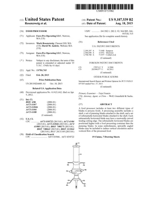
  • 1. (12) United States Patent US009107539B2 (10) Patent No.: US 9,107,539 B2 Rosenzweig et al. (45) Date of Patent: Aug. 18, 2015 (54) FOOD PROCESSOR USPC .............. 241/282.1, 282.2, 92; 366/205, 246; 99/510,513 (71) Applicant: Euro-Pro Operating LLC, Newton, Seeapplication file forcomplete search history. MA (US) (72) Inventors: Mark Rosenzweig, Chesnut Hill, MA (56) References Cited (US); David M. Audette, Webster, MA U.S. PATENT DOCUMENTS (US) 2,209.287 A 7/1940 Simpson (73) Assignee: Euro-Pro Operating LLC, Newton, 2,546,949 A 3, 1951 Morrison MA (US) 2,798,700 A 7, 1957 Corbett et al. (Continued) (*) Notice: Subject to any disclaimer, the term ofthis patent is extended or adjusted under 35 FOREIGN PATENT DOCUMENTS U.S.C. 154(b) by 61 days. CN 2787 112 Y 6,2006 (21) Appl. No.: 13/781,743 CN 2O1996377 U. 10,2011 (Continued) (22) Filed: Feb. 28, 2013 OTHER PUBLICATIONS (65) Prior Publication Data International Search Report and Written Opinion for PCT/US2013/ US 2013/0264401 A1 Oct. 10, 2013 057205 mailed Nov. 27, 2013. Continued Related U.S. Application Data ( ) (60) gynal application No. 61/621,662, filed on Apr. Primary Examiner— Faye Francis s (74) Attorney, Agent, or Firm — Wolf, Greenfield & Sacks, (51) Int. Cl. P.C. B2C 4/06 (2006.01) A47. 43/07 (2006.01) (57) ABSTRACT if: te? 3. A food processor includes at least two different types of A47. 43/08 R blades to process foods. A processing assembly includes a ( .01) shaft, aset ofpureeing blades attached to the shaft,and a set (Continued) ofsubstantially horizontal blades attached to the shaft. Each (52) U.S. Cl. substantially horizontal blade may have a rearwardly curved CPC .............. A47J 43/0722 (2013.01); A47J 43/04 leading cutting edge. The Substantially horizontal blades are (2013.01); A47J 43/046 (2013.01); A47J positioned higher with a food processing container than the 43/085 (2013.01); B0IF 7/00275 (2013.01); pureeing blades. In some embodiments, upwardly angled BOIF 7/00641 (2013.01); B0IF 13/1044 blades may be included to induce vertical circulation and/or (2013.01); B01F2013/108 (2013.01) vorticial flow ofthe processed food. (58) Field ofClassification Search CPC ............................ A47J 43/046; A47J 43/0722 19 Claims, 7 Drawing Sheets
  • 2. US 9,107,539 B2 Page 2 (51) Int. C. 6,981,795 B2 1/2006 Nikkah BOIF 7700 (2006.01) 6,986,476 B2 1/2006 Unteregger 7,318,375 B2 1/2008 Huang BOIF I3/10 (2006.01) 7.350.963 B2 4/2008 Williams etal. 7,395,751 B2 7,2008 Liu (56) References Cited 7,404,665 B2 7/2008 Bacher et al. 7,422,169 B2 9,2008 Mueller U.S. PATENT DOCUMENTS 7,552,885 B2 6/2009 Katz et al. 7,585,102 B2 9,2009 Bacher et al. 2,807.447 A 9/1957 Vaughan 7,677,485 B2 * 3/2010 Gursel ....................... 241,282.1 2.930,596 A 3, 1960 Waters 7,685,933 B2 3/2010 Fevre 4,071,789 A 1/1978 Ernster et al. 8,197,121 B2 6,2012 Sands 4,256.407 A 3, 1981 Seiderman 8,251.573 B2 8,2012 Chou 4,274,023 A 6/1981 Lamprey 2006, O158958 A1 7/2006 Romanik 4,339,205 A 7, 1982 Kato et al. 2009/0090254 A1 4/2009 Herren 4,403,868 A 9/1983 Kupka 2009.0109793 A1 4/2009 Xue 4,480,926 A 11/1984 Lattery, Jr. et al. 2009, O190439 A1 7/2009 Yeung 4,509,860 A 4, 1985 Lasar, III 2009,0193982 A1 8,2009 Chou 4,854,720 A 8, 1989 Schold 2011/0101138 A1 5/2011 Unteregger et al. 4,911,557 A 3, 1990 Dormer et al. 2011/O185920 A1 8,2011 Oblak et al. 5,190,375 A 3, 1993 Shiobara 2011/0226140 A1 9,2011 Herren 5,213,415 A 5, 1993 Saeki 2012/0129643 A1 5/2012 Cheung et al. 5,350,235 A 9/1994 Hagen et al. 2013/0264404 A1 10/2013 Rosenzweig etal. 5,460,444 A 10, 1995 Howorka 5.487,511 A 1/1996 Sansone et al. FOREIGN PATENT DOCUMENTS 5,533,801 A 7, 1996 Safont et al. 5,823,672 A 10, 1998 Barker EP O O22 465 A1 1, 1981 5,823,673 A 10, 1998 Muntener EP O 57O 685 A 11, 1993 6,012,837 A 1/2000 Thuma EP O 529 287 B1 9,1995 6,050,720 A 4/2000 Tuyuki GB 1447 430 A 8, 1976 6,164,812 A 12/2000 Brezovnik et al. GB 23O3 537 A 2, 1997 6,189,441 B1 2/2001 Beaudet et al. WO WOOO,36960 A1 6,2000 6,227,698 B1 5/2001 Muntener WO WO 2012/113667 A1 8,2012 6.255,751 B1 7/2001 Hoffmann 6,280,076 B1 8/2001 Muntener OTHER PUBLICATIONS 6,364,226 B1 4/2002 Kubicko 6,604,455 B2 8/2003 Areh et al. International Search Report and Written Opinion for PCT/US2013/ 6,609,821 B2 8, 2003 Wulfetal. 057210 mailed Dec. 18, 2013 6,640,693 B2 11/2003 Brezovniket al. to: 6,655.265 B2 12,2003 Pavlovic et al. No Author Listed NinjaTM. Professional Blender. NJ600 30. Own 6,681,687 B2 1/2004 Areh et al. er's Guide. 2010. 11 pages. 6,690,128 B1 2/2004 Cotton et al. D513,685 S 1/2006 Katz et al. * cited by examiner
  • 3. US 9,107,539 B2Sheet 1 of 7Aug. 18, 2015U.S. Patent FIG. 1
  • 4. US 9,107,539 B2 NNNNNR Sheet 2 of 7 W Z 22 2 Aug. 18, 2015U.S. Patent d &S& K 2ZZZZZZZZZZZZ
  • 5. U.S. Patent Aug. 18, 2015 Sheet 3 of7 US 9,107,539 B2 FIG 3
  • 6. U.S. Patent Aug. 18, 2015 Sheet 4 of7 US 9,107,539 B2
  • 7. U.S. Patent Aug. 18, 2015 Sheet 5 Of 7 US 9,107,539 B2
  • 8. U.S. Patent Aug. 18, 2015 Sheet 6 of7 US 9,107,539 B2
  • 9. U.S. Patent Aug. 18, 2015 Sheet 7 Of 7 /_QRVZs>AZN<<Ng
  • 10. US 9,107,539 B2 1. FOOD PROCESSOR RELATED APPLICATIONS This Application claims the benefit under 35 U.S.C. S119 (e)ofU.S. ProvisionalApplicationSer. No. 61/621,662, filed onApr. 9, 2012. FIELD Aspects herein generally relate to food processors, pro cessingassemblies for food processors, and methods ofpro cessing food. More specifically, aspects disclosed herein relateto aprocessing assemblies with certain blade arrange mentS. DISCUSSION OF RELATED ART Food processors such as blenders use a rotating blade assemblies to process food. Some food processors include substantially horizontal blades which perform well when chopping ice or large food items. SUMMARY According to one embodiment of the invention, a food processor blade assembly includes a shaft having an axis of rotation, afirst,lowersetofblades rotatableby theshaftabout the axis ofrotation, and a second, higher set ofblades rotat able by the shaft about the axis ofrotation, the second set of blades positioned higher on the shaft than the first set of blades.The first, lowersetofblades includes firstandsecond blades, each blade having at least a portion angled down wardly relative to a horizontal plane. The first, lower set of blades includes thirdand fourth blades, each blade having at leastaportionangledupwardly relativeto a horizontalplane, the upwardly angled portions ofthe third and fourth blades beingpositionedhigherthanthedownwardlyangledportions ofthefirstandsecondblades.Thesecond,highersetofblades includes fifth andsixthblades,each ofwhichisasubstantially horizontal blade having a rearwardly curved leading cutting edge. According to another embodiment, a food processing apparatus includes a motor, a food processing container, and a processing assembly configured to be rotated within the food containerby the motor. The blade assembly includes a shaft having an axis of rotation, a first, lower set of blades rotatableby the shaftabout theaxisofrotation, andasecond, higher set ofblades rotatable by the shaft about the axis of rotation. The second set ofblades is positioned higheron the shaft than the first set ofblades. The first, lowerset ofblades includes firstand second blades, each bladehaving at least a portionangleddownwardly relativetoahorizontalplane.The first, lowersetofbladesincludes thirdandfourthblades,each blade having at least a portion angled upwardly relative to a horizontal plane, the upwardly angled portions ofthe third and fourth blades being positioned higher than the down wardly angled portions of the first and second blades. The second, higher set ofblades includes fifth and sixth blades, each of which is a substantially horizontal blade having a rearwardly curved leading cutting edge. Accordingtoanotherembodiment,a method ofprocessing food includes associatinga food processing containerwith a drive assembly, wherein the food processing container including a blade assembly. The method further includes adding foodto the foodprocessingcontainer, andprocessing food with thebladeassembly. Theactofprocessing includes 10 15 25 30 35 40 45 50 55 60 65 2 chopping the food with a set of substantially horizontal blades, each Substantially horizontal blade having a rear wardly curved leading cutting edge, and blending the food with a set of downwardly angled blades, the downwardly angledbladesbeingpositionedlowerwithinthefoodprocess ing container relative to the set of substantially horizontal blades. The method also includes vertically circulating the food with a set of upwardly angled blades, the upwardly angled blades being positioned higherthan the set ofdown wardly angled blades and lower than the set ofsubstantially horizontal blades. BRIEF DESCRIPTION OF DRAWINGS Theaccompanying drawings are not intended to be drawn to scale. In the drawings, each identical or nearly identical componentthatis illustrated in various figures is represented by a like numeral. Forpurposes ofclarity, not every compo nent may be labeled in every drawing. Various embodiments ofthe invention will now be described, by way ofexample, with reference to the accompanying drawings, in which: FIG. 1 is a side view showing a food processing assembly according to one embodiment; FIG.2 isacross-sectional view ofafoodprocessoraccord ing to one embodiment; FIG.3 isaperspective view ofabladeassembly according to one embodiment; FIG. 4 is a top view ofa blade assembly according to one embodiment; FIG. 5 is a side view ofa blade assembly according to one embodiment; FIG. 6 isaperspective view ofabladeassembly according to anotherembodiment; and FIG. 7 is an enlarged view that depicts the interface between a drive coupler and a driven coupler in accordance with an aspect ofthe invention. DETAILED DESCRIPTION A food processing assembly is provided herein which includes different blade types to effectively process food, includingfoodwhichistypically difficulttoprocess. In some embodiments, the processing assembly includes a set of bladeswhichareeffectiveatpureeingand/orcreatingaVortex and/or a vertical circulation of blended food. This set of blades may be positioned within a lower quarter of a food container when the processing assembly is put into place within the container. A second set of blades comprising a different type ofblade may be positioned at a higher level within the food container as compared to the lower set of puree blades. In some embodiments, this upper setofblades may include substantially horizontal blades which are effec tive at chopping ice and/or large food articles. By providing both types ofblades, food and ice may be effectivelyandquickly choppedandpureed.Additionally,the lower set ofblades may be provided with blades thatcreate a vertical circulation ofblended food. In some embodiments, these blades maybeangled upwardlyjustabovedownwardly angledpureeblades. By rotating the upwardly angled blades atahigh rotation rate, forexample,at 18,000 rpmorhigherin Some embodiments, a vertical circulation quickly moves blended food upwardly and away from the puree blades, while drawing unblended or less blended food downwardly into thepuree blades. Inthis manner, mostorall ofthefoodin thecontainerisprocessedby thepuree blades. Similarly, this vertical circulation helps move food through a Zone where it may be chopped by the set of horizontal blades. In some
  • 11. US 9,107,539 B2 3 embodiments, some or all of the blades of the processing assembly create a vortex ofliquid flow. Horizontal blades ofthe types disclosed herein are typi cally rotated at speeds lower than 18,000 rpm because dam age to the blade and/or breakage ofthe connection between the bladeand shaft can occur. According to oneembodiment disclosed herein, the horizontal blades are made with stain less steel and are welded to a stainless Steel shaft. In some embodiments, the welded blade and shaft arrangement is overmolded with plastic. As used herein, the term “processing tool refers to any tool used to process foods and other materials. Processing tools may include, but are not limitedto, a blade assembly, a whisk, an ice crushing assembly, a dicing assembly, a grater, and a shredder. A blade assembly may contain a single blade or more than one blade. As used herein, the term “food’ includesany solid orliquid comestible, andany mix between a solid and a liquid. For purposes herein, a blade does not necessarily have to include a sharp, leading edge. As used herein, the terms “connected,” “attached, or “coupled are not limited to a direct connection, attachment, orcoupling, as two components may be connected,attached, or coupled to one another via intermediate components. According to oneembodiment, as shown in FIG. 1, a pro cessing assembly 100 includes a rotatable shaft 102 with a first set ofblades 104, a second set ofblades 106, anda third setofblades 108. Insomeembodiments,thefirstsetofblades 104 may be positioned lower on the shaft than other sets of blades. First set ofblades 104 may include blades which are upwardly and/or downwardly angled. Such an arrangement may help to create a vertical circulation within the food containing Volume to enhance mixing and circulation ofthe food, thereby promoting moreeffective pureeingofthefood. In oneembodiment,as shown in FIG. 1, thefirst setofblades 104includesa firstupwardlyangledblade 110aandasecond upwardly angle blade 110b which is not shown in FIG. 1 but ispositionedon an opposite sideofshaft 102 from blade 110. First setofblades 104 also includes two downwardly angled blades 112a, 112b. Downwardly angled blades 112a, 112b may be particularly effective at pureeing and/or liquefying food in some embodiments. In some cases, the upwardly angled and the downwardly angled blades may be formed from a single unitary body, as shown in FIG. 3. In other cases, the blades may be joined together via welding or other Suitable arrangement. The upwardly angled blades 110a, 110b and downwardly angled blades 112a, 112b do not have to be directly connected for these blades to be considered to be part ofa set ofblades. Secondsetofblades 106 includesblades114a, 114bwhich are substantially horizontal when the overall processing assemblyismountedinablenderorotherfoodprocessor.The horizontal blades may be particularly effective in chopping ice orlarge food items. In some cases, blade 114a and blade 114b may be formed from a single unitary component. In other cases, each of blades 114a, 114b may be separate blades. Blades 114a, 114b may be attached to shaft 102 via welding or other Suitable manner. In some embodiments, blades 114a, 114b and shaft 102 are constructed ofstainless steel and welded together. Third set of blades 108 includes blades 116a and 116b, which are also substantially horizontal blades in some embodiments. As with secondsetofblades 106, blades 116a and 116b maybeseparate from oneother, orpartofa unitary bladeassembly. Theseblades may be welded to shaft 102, or otherwise Suitably attached, such asby overmolding in some embodiments. 5 10 15 25 30 35 40 45 50 55 60 65 4 A driven coupler 210 may be positioned at a bottom of processing assembly 100 to be driven by an associated drive coupler ofa food processorbase. Any suitable drive mecha nism may be employed with embodiments herein. A Support member 212 may be positioned at a top of shaft 102 to interface with a lid ofa foodprocessing container in Support ofrotationaboutanaxis ofrotation 117.Thesupport member may be allowed to rotated within a recess in the lid in some embodiments. A food processing apparatus 200 is shown in FIG. 2 and includes a lid 202, a container 204, and a base 206. The container 204 removably engages with the base 206 via a locking mechanism 105 which includes a collection ofpro trusions and indents on the base 206 and the container 204. The containercan be removably fixed to the baseby placing thecontainer204onto thebase206andtwistingthecontainer 204 relative to thebase206 to engage themechanical locking mechanism 105 between the container and the base. Any Suitable locking mechanism can be used, as thisaspect is not limiting. For example, the container may engage with the base by pressing the container down onto the base or by slidingthecontainerlaterally ontothebase. In someembodi ments, the container does not lock or engage with the base, but instead only operatively interacts with the base, for example to receive rotational power from the base. Thecontainer204 may beany suitable volumeanddesign. In some cases, the container is a small single-serve jar that may be used as a drinking cup aftertheprocessing assembly is removed from the jar. In some cases, the container is a largerpitcherthat can hold multiple servings. The container may include a handle and a spout to facilitate pouring of contents and/or the lifting and moving ofthe container. The lid202 may includea hole through which foodcanpass such that food can be added to or removed from the food-contain ing volume 205 without removing the lid 202 from the con tainer204. Acap may beusedto coveroruncoversuch a hole inthelid.Thecap mayattachtothelidinanySuitablemanner, forexample, via threads thatallow thecap to be screwedonto the lid, by a hinge that connects the cap to the lid, or via an interference fit, as this aspect is not limited in this regard. Foodprocessingapparatus200 may includetheprocessing assembly 100illustrated in FIG. 1 within thefood-containing volume205. As usedherein, the“food-containingvolume” is the volume in the container within which food is located during food processing. The base206 includes a motor 110 which is connected toa drive shaft 120, which in turn is connected to a drivecoupler 130. The drive coupler 130 interfaces with a driven coupler 210 ofthe processing assembly 215, as shown in FIG. 2. In some embodiments, the drive coupler 130 and the driven coupler210 can be removably coupled to one another. In one embodiment, the driven coupler 210 is attached to the con tainer204 such that, when the container204 is lifted offthe base 100, the driven coupler 210 is removed from the drive coupler 130. In other embodiments, the drive coupler 130 may bepermanently attached to the driven coupler 210. FIG. 7showsanenlargedview oftheinterfacebetweenthe drive coupler 130 and the driven coupler 210. The drive coupler 130 may include a recess with a plurality ofprotrud ingteeth 131. Any suitable numberofteeth 131 may beused. When the recess ofthe drive coupler 130 receives the driven coupler 210, the motor 110 becomes connected to the pro cessingassembly 100. In some embodiments, the shaftand associated blades are rotated at 24,000 RPM, 25,000 RPM or higher. In some embodiments, the shaft and associated blades are rotated at 18,000 RPM. In some embodiments, a control panel is pro
  • 12. US 9,107,539 B2 5 vided and a user can adjust or select speeds from a provided range of speeds. In some embodiments, the rotation speeds may vary from 5,000 RPM up to 18,000 RPM orhigher.The blades or other processing tools may be rotated at various speeds that are suitable for shredding, grating, slicing, or chopping, in some embodiments. In some embodiments, a speed reduction assembly, Such as a gear assembly, may be providedonanundersideofcontainer204and/orwithin base 206. The above described components may be made with vari ous materials,andtheaboveaspects may beemployedinany Suitable combination. Having thus described several aspects of at least one embodiment of this invention, it is to be appreciated that various alterations, modifications, and improvements will readily occur to those skilled in the art. Such alterations, modifications, and improvements are intended to be part of this disclosure, and are intended to be within the spirit and Scope of the invention. Accordingly, the foregoing descrip tion and drawings are by way ofexample only. FIG. 3 illustrates one embodiment of a set of upwardly angled blades and downwardly angled blades and described above. In the illustrated embodiment, each of downwardly angled blades 112a, 112b includesa horizontal bladeportion 140a, 140bextending from its respectiveend.Thesehorizon tal extensions can help puree food in Some embodiments by Squeezingpartially liquefiedfoodbetweentheextensionsand a base ofthe container. Zero, one, two, three or all ofblades 110a, 110b, 112a and 112b may include a sharp, cutting leading edge. FIG. 4 is a top view oftwo sets ofsubstantially horizontal blades. A first set 302 of horizontal blades include two opposedblades304a,304b. Insomeembodiments, morethan two blades may be provided in any given set ofblades. For example, four blades positioned around the shaft at ninety degree intervals may be used in Some embodiments. A second set 306 ofblades 308a, 308b is angularly posi tionedata ninetydegreeanglerelativetofirsset302ofblades in the illustrated embodiment. Ofcourse, this second set of blades 306 can be angularly positioned at any suitable posi tion. Each ofthe blades shown in FIG. 4 has a sharp, leading cutting edge 310. Additionally, on each of the blades, the leadingcuttingedgeis rearwardly curvedrelativeto the rota tion direction.As shownin FIG.4,onesetofblades (e.g., first set302)maybemountedtoa shaftportion312havingalarger diameter than otherportions ofthe shaft. FIG. 5 shows one particular embodiment offour substan tially horizontal blades which include rearwardly curved leading, cutting edges. Each ofthe blades in the illustrated embodiment has a maximum thickness t of 1.2 mm, with a thinner section at the leading edge. Of course, other thick nesses may be provided, and not all ofthe blades need have the same thickness. A distance H1 from a lowest pointofthe shaft-bladeconnectionto a lowest horizontal blade is 2.6 mm in the illustrated embodiment, while a distance H2 from the lowest point to a second blade is 13 mm. A third blade is positionedata distance H3 of35 mm from thelowest pointof the shaft-bladeconnectionintheillustratedembodiment,and a fourth blade is positioned at distance of45 mm from the lowest point. Ofcourse, any Suitable distances may be used, and two or more blades may be located at a same distance from the lowestpoint.Theupperandlowerblades ineach set may differ in height from each other by about 10-12 mm in some embodiments. The lowerbladeofthe upperset may be about22 mm higherthanthe upperbladeofthelowerset.The tip ofone blade may be horizontally distanced by approxi mately 57 mm from the tip ofa directly opposed blade in 10 15 25 30 35 40 45 50 55 60 65 6 Some embodiments. Ofcourse, in Some embodiments, only one or only two substantially horizontal blades may be pro vided on the shaft of the processing assembly. Further, in Some embodiments, one, some, or all of the Substantially horizontal blades thatare provided may be positioned below any provided puree or vertical mixing blades, such as down wardly angled blades and upwardly angled blades. FIG. 6 shows another embodiment ofa processing blade assembly 400. In this embodiment, no upwardly angled blades are provided. Two downwardly angled blades 402a, 402b are positioned at a lower end of a shaft 404. These downwardly angledblades may bepositioned Such thathori Zontal portions 405a, 405b are positioned within the lowest quarter of an associated food container. In some embodi ments, the blades may be positioned such that horizontal portions405a,405barepositionedwithinthelowesteighthof an associated food container. Verticallyoffset substantially horizontalblades 406a,406, 408a and 408b areprovided above blades 402a, 402b in this embodiment. In some embodiments, the blade assembly may be driven by a motorand/ordrive coupling locatedat a top ofshaft404 which engages with a driven coupler 412. Or, the blade assembly may be driven by a drive coupling located at a bottom ofthe blade assembly. Having thus described several aspects of at least one embodiment of this invention, it is to be appreciated that various alterations, modifications, and improvements will readily occur to those skilled in the art. Such alterations, modifications, and improvements are intended to be part of this disclosure, and are intended to be within the spirit and scope ofthe invention. Accordingly, the foregoing descrip tion and drawings are by way ofexample only. What is claimed is: 1. A food processor blade assembly comprising: a shafthaving an axis ofrotation; a first, lower set ofblades rotatable by the shaft about the axis ofrotation; and a second, higher set ofblades rotatable by the shaft about the axis ofrotation, the second set ofblades positioned higheron the shaft than the first set ofblades; wherein: the first, lower set of blades includes first and second blades, each blade having at least a portion angled downwardly relative to a horizontalplaneanda hori Zontal portion extending from an end ofthe down ward angled portion; the first, lower set of blades includes third and fourth blades, each blade having at least a portion angled upwardly relative to a horizontal plane, the upwardly angled portions ofthe third and fourth blades being positioned higher than the downwardly angled por tions ofthe first and second blades; and the second, higher set ofblades includes fifth and sixth blades, each of which is a substantially horizontal blade having a rearwardly curved leading cutting edge. 2. The food processor blade assembly as in claim 1, whereinthefifth,substantiallyhorizontalbladeofthesecond, higher set ofblades is positioned higher than the sixth, sub stantially horizontalbladeofthe second,highersetofblades. 3. The processor blade assembly as in claim 1, further comprisinga thirdsetofblades, thethird setofblades includ ing seventhandeighthblades,each ofwhichisaSubstantially horizontal bladeand has a rearwardly curved leading cutting edge,and wherein the third setofblades is positionedhigher than the second set ofblades.
  • 13. US 9,107,539 B2 7 4. The food processor blade assembly as in claim 3, wherein the seventh, substantially horizontal blade of the third set ofblades is positioned higher than the eighth, sub stantially horizontal blade ofthe third set ofblades. 5.Theprocessorbladeassemblyas inclaim 1, wherein the horizontal blade portionofeach ofthefirstand secondblades has a leading cutting edge. 6.Theprocessorbladeassembly as inclaim 1, wherein the shaft is a substantially vertical shaft. 7. The processor blade assembly as in claim 1, wherein eachofthefirstandsecondbladeshasa sharp,cuttingedgeas a leading edge. 8. The processor blade assembly as in claim 1, wherein eachofthethirdandfourthbladeshasasharp,cuttingedgeas a leading edge. 9. A food processingapparatus comprising: a motor; a foodprocessing container, and a processing assembly configured to be rotated within the food containerby the motor; wherein the blade assembly includes: a shaft having an axis ofrotation; afirst, lowersetofblades rotatableby theshaftaboutthe axis ofrotation; and asecond,highersetofbladesrotatablebytheshaftabout the axis of rotation, the second set of blades posi tioned higheron the shaft than the first set ofblades: wherein: the first, lowerset ofblades includes first and second blades, each bladehavingat least aportionangled downwardly relative to a horizontal plane and a horizontal portion extending from an end of the downward angled portion: the first, lowerset ofblades includes thirdand fourth blades, each bladehavingat leasta portion angled upwardly relative to a horizontal plane, the upwardly angled portions of the third and fourth blades being positioned higher than the down wardly angled portions of the first and second blades; and the second, higher set of blades includes fifth and sixth blades, each ofwhich is a substantially hori Zontal blade having a rearwardly curved leading cuttingedge. 10. The food processing apparatus as in claim 9, wherein the fifth, substantially horizontal bladeofthesecond, higher setofbladesispositionedhigherthanthesixth, substantially horizontal blade ofthe second, higherset ofblades. 10 15 25 30 35 40 45 8 11. The food processing apparatus as in claim 9, further comprisingathirdsetofblades, thethirdsetofblades includ ingseventhandeighthblades,eachofwhichisasubstantially horizontalbladeandhasa rearwardlycurved leadingcutting edge,andwhereinthethirdsetofbladesispositionedhigher than the second set ofblades. 12.The food processingapparatus as in claim 11, wherein the seventh, substantially horizontal blade ofthe third set of bladesispositionedhigherthantheeighth,substantiallyhori Zontal blade ofthe third set ofblades. 13. The food processing apparatus as in claim 9, wherein the horizontal blade portion ofeach ofthe first and second blades has a leading cutting edge. 14. The food processing apparatus as in claim 9, wherein the shaft is a substantially vertical shaft. 15.A methodofprocessing food comprising: associatingafoodprocessingcontainerwithadriveassem bly, the food processing container including a blade assembly; adding food to the food processing container; processing food with the blade assembly, the act ofpro cessingincluding: chopping the food with a set of substantially horizontal blades,eachsubstantiallyhorizontalbladehavingarear wardly curved leading cutting edge; blendingthefoodwithasetofdownwardlyangledblades, the downwardly angled blades being positioned lower withinthe foodprocessingcontainerrelativetothesetof substantially horizontal blades, and each downwardly angledbladehavingahorizontalportionextendingfrom an end ofa downwardly angled portion; and vertically circulating the food with a set of upwardly angled blades, the upwardly angled blades being posi tionedhigherthan the set ofdownwardly angled blades andlowerthanthesetofsubstantiallyhorizontalblades. 16.The methodas in claim 15, wherein theset ofsubstan tiallyhorizontalbladesincludes foursubstantiallyhorizontal blades,eachpositionedatadifferentverticalpositionthanthe others ofthe foursubstantially horizontal blades. 17.Themethodasinclaim 15, furthercomprisingcreating a vorticial flow by rotating the upwardlyangled blades. 18. The method as in claim 17, wherein rotating the upwardly angled blades comprises rotating the upwardly angled blades ata rotation speed ofat least 18,000 RPM. 19. The method as in claim 18, wherein rotating the upwardly angled blades comprises rotating the upwardly angled blades at a rotation speed of no more than 25,000 RPM. ck ck ck ck ck