Usd510466
•
0 likes•20 views

Inventors and entrepreneurs have vocations fueled by passion. Many would have done it for free or as a hobby if it hadn’t become a profession. Mark Rosenzweig is a natural creator, driven by his passion. This fuel has led Mark to develop his ideas into viable products and innovations that he has been patenting since 2003. From an innovative filter sensor and indicator for vacuum cleaners to a basket for deep fryer and methods of cooking food products to a compact cyclonic bagless vacuum cleaner. Sometimes independently and often as part of creative teams, Mark has patented just under one hundred innovative inventions between 2003 and 2017.
Report
Share
Report
Share
Download to read offline

Recommended
Recommended
Falcon stands out as a top-tier P2P Invoice Discounting platform in India, bridging esteemed blue-chip companies and eager investors. Our goal is to transform the investment landscape in India by establishing a comprehensive destination for borrowers and investors with diverse profiles and needs, all while minimizing risk. What sets Falcon apart is the elimination of intermediaries such as commercial banks and depository institutions, allowing investors to enjoy higher yields.Falcon Invoice Discounting: The best investment platform in india for investors
Falcon Invoice Discounting: The best investment platform in india for investorsFalcon Invoice Discounting
More Related Content
More from Mark Rosenzweig
More from Mark Rosenzweig (20)
Recently uploaded
Falcon stands out as a top-tier P2P Invoice Discounting platform in India, bridging esteemed blue-chip companies and eager investors. Our goal is to transform the investment landscape in India by establishing a comprehensive destination for borrowers and investors with diverse profiles and needs, all while minimizing risk. What sets Falcon apart is the elimination of intermediaries such as commercial banks and depository institutions, allowing investors to enjoy higher yields.Falcon Invoice Discounting: The best investment platform in india for investors
Falcon Invoice Discounting: The best investment platform in india for investorsFalcon Invoice Discounting
Saudi Arabia [ Abortion pills) Jeddah/riaydh/dammam/++918133066128☎️] cytotec tablets uses abortion pills 💊💊 How effective is the abortion pill? 💊💊 +918133066128) "Abortion pills in Jeddah" how to get cytotec tablets in Riyadh " Abortion pills in dammam*💊💊 The abortion pill is very effective. If you’re taking mifepristone and misoprostol, it depends on how far along the pregnancy is, and how many doses of medicine you take:💊💊 +918133066128) how to buy cytotec pills
At 8 weeks pregnant or less, it works about 94-98% of the time. +918133066128[ 💊💊💊 At 8-9 weeks pregnant, it works about 94-96% of the time. +918133066128) At 9-10 weeks pregnant, it works about 91-93% of the time. +918133066128)💊💊 If you take an extra dose of misoprostol, it works about 99% of the time. At 10-11 weeks pregnant, it works about 87% of the time. +918133066128) If you take an extra dose of misoprostol, it works about 98% of the time. In general, taking both mifepristone and+918133066128 misoprostol works a bit better than taking misoprostol only. +918133066128 Taking misoprostol alone works to end the+918133066128 pregnancy about 85-95% of the time — depending on how far along the+918133066128 pregnancy is and how you take the medicine. +918133066128 The abortion pill usually works, but if it doesn’t, you can take more medicine or have an in-clinic abortion. +918133066128 When can I take the abortion pill?+918133066128 In general, you can have a medication abortion up to 77 days (11 weeks)+918133066128 after the first day of your last period. If it’s been 78 days or more since the first day of your last+918133066128 period, you can have an in-clinic abortion to end your pregnancy.+918133066128
Why do people choose the abortion pill? Which kind of abortion you choose all depends on your personal+918133066128 preference and situation. With+918133066128 medication+918133066128 abortion, some people like that you don’t need to have a procedure in a doctor’s office. You can have your medication abortion on your own+918133066128 schedule, at home or in another comfortable place that you choose.+918133066128 You get to decide who you want to be with during your abortion, or you can go it alone. Because+918133066128 medication abortion is similar to a miscarriage, many people feel like it’s more “natural” and less invasive. And some+918133066128 people may not have an in-clinic abortion provider close by, so abortion pills are more available to+918133066128 them. +918133066128 Your doctor, nurse, or health center staff can help you decide which kind of abortion is best for you. +918133066128 More questions from patients: Saudi Arabia+918133066128 CYTOTEC Misoprostol Tablets. Misoprostol is a medication that can prevent stomach ulcers if you also take NSAID medications. It reduces the amount of acid in your stomach, which protects your stomach lining. The brand name of this medication is Cytotec®.+918133066128) Unwanted Kit is a combination of two medicines, ounwanted pregnancy Kit [+918133066128] Abortion Pills IN Dubai UAE Abudhabi
unwanted pregnancy Kit [+918133066128] Abortion Pills IN Dubai UAE AbudhabiAbortion pills in Kuwait Cytotec pills in Kuwait
+971581248768>> SAFE AND ORIGINAL ABORTION PILLS FOR SALE IN DUBAI AND ABUDHABI}}+971581248768in dubai+971581248768_)whatsapp*abortion pills in dubai/buy cytotec misoprostol and mifepristone in dubai
More arrow_drop_down
WHATSAPP +971581248768 ABORTION PILLS IN DUBAI,MISOPROSTOL IN DUBAI,@CYTOTEC TABLETS IN DUBAI/cytotec in abu dhabi/abortion pills in sharjah/MIFEPRISTONE IN DUBAI/misoprostol in ajman/@abortion pills in ras al khaimah@mifepristone in sharjah>mifepristone in abu dhabi>ABORTION PILLS FOR SALE IN ABU DHABI,KUWAIT,AJMAN,SHARJAH,RAS AL KHAIMAHSALMIYA,AL WAKRAH,JOHANNESBURG,AL AIN,CYTOTEC IN DUBAI+971581248768 cytotec price in dubai,abu dhabi.al ain,ajman,sharjah,,OTTAWA,ALBERTA,CALGARY,TORONTO,IDAHO,OHIO, Midrand ,Sandton,Hyde Park,Johannesburg,New Hampshire,South Dakota,North Dakota,how how can i get abortion pills in dubai ,abu dhabi,,riyadh.oman.muscat,Arkansas ,Kansas,West Virginia, abortion pills in for sale in dubai.abu dhabi+971581248768 Oklahoma,Nebraska,Vermont,Idaho,South Carolina,Wisconsin ~ misoprostol price in dubai.ajman.al ain.kuwaitcity,Alabama,Maine,New Mexico, soweto+971581248768,cytotec pills in kuwait,sharjah,ajman,ras al khaimahMissouri,, un wanted kit in dubai, Victoria, Sydney, ajman, Botswana ,misoprostol in abu dhabi.sharjah.dubai Alabama,get abortion pills in ras al khaimah,al ain,ajman,abu dhabi.sharjah,kuwaitcity,al satwa,deira. Charlotte,Austin,San Francisco,New York,Seattle,farwaniyah,cytotec pills for sale in al ain ,ajman,dubai,Washington,misoprostol tablets available +971581248768 in dubai,abu dhabi,sharjah,al ain,deira,ajman) abortion pills in abu dhabi,sharjah,dubai,fujairah,jumeirah,ras al khaimah,Rockhampton,Toowoomba,Coffs Harbour,J!~+971581248768>> SAFE AND ORIGINAL ABORTION PILLS FOR SALE IN DUBAI AND ABUD...
!~+971581248768>> SAFE AND ORIGINAL ABORTION PILLS FOR SALE IN DUBAI AND ABUD...DUBAI (+971)581248768 BUY ABORTION PILLS IN ABU dhabi...Qatar
Recently uploaded (20)
Falcon Invoice Discounting: The best investment platform in india for investors
Falcon Invoice Discounting: The best investment platform in india for investors
Falcon's Invoice Discounting: Your Path to Prosperity
Falcon's Invoice Discounting: Your Path to Prosperity
HomeRoots Pitch Deck | Investor Insights | April 2024
HomeRoots Pitch Deck | Investor Insights | April 2024
Horngren’s Cost Accounting A Managerial Emphasis, Canadian 9th edition soluti...
Horngren’s Cost Accounting A Managerial Emphasis, Canadian 9th edition soluti...
unwanted pregnancy Kit [+918133066128] Abortion Pills IN Dubai UAE Abudhabi
unwanted pregnancy Kit [+918133066128] Abortion Pills IN Dubai UAE Abudhabi
Power point presentation on enterprise performance management
Power point presentation on enterprise performance management
How to Get Started in Social Media for Art League City
How to Get Started in Social Media for Art League City
New 2024 Cannabis Edibles Investor Pitch Deck Template
New 2024 Cannabis Edibles Investor Pitch Deck Template
Over the Top (OTT) Market Size & Growth Outlook 2024-2030
Over the Top (OTT) Market Size & Growth Outlook 2024-2030
!~+971581248768>> SAFE AND ORIGINAL ABORTION PILLS FOR SALE IN DUBAI AND ABUD...
!~+971581248768>> SAFE AND ORIGINAL ABORTION PILLS FOR SALE IN DUBAI AND ABUD...
Rice Manufacturers in India | Shree Krishna Exports
Rice Manufacturers in India | Shree Krishna Exports
Falcon Invoice Discounting: Tailored Financial Wings
Falcon Invoice Discounting: Tailored Financial Wings
Lundin Gold - Q1 2024 Conference Call Presentation (Revised)
Lundin Gold - Q1 2024 Conference Call Presentation (Revised)
Al Mizhar Dubai Escorts +971561403006 Escorts Service In Al Mizhar
Al Mizhar Dubai Escorts +971561403006 Escorts Service In Al Mizhar
Usd510466
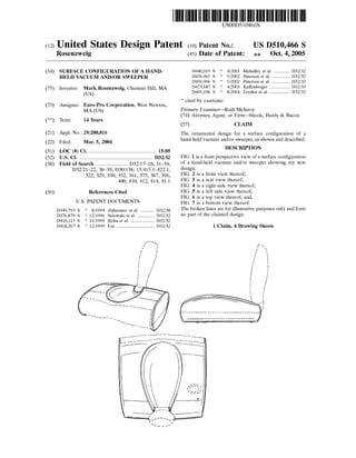
- 1. USOOD510466S (12) United States Design Patent (10) Patent No.: US D510,466 S Rosenzweig (45) Date of Patent: : - Oct. 4, 2005 (54) SURFACE CONFIGURATION OFA HAND- D440,019 S 4/2001 Mehaffey et al. ............ D32/32 HELD WACUUMAND/OR SWEEPER D456,965 S * 5/2002 Paterson et al. ...... ... D32/32 D456,966 S * 5/2002 Paterson et al. ...... ... D32/32 (75) Inventor: Mark Rosenzweig, Chestnut Hill, MA D473,687 S 4/2003 Kaffenberger ..... ... D32/33 (US) D495,106 S 8/2004 Leyden et al. ............... D32/32 * cited by examiner (73) Assignee: Euro-Pro Corporation, West Newton, MA (US) Primary Examiner Ruth McInroy (74) Attorney, Agent, or Firm-Shook, Hardy & Bacon (**) Term: 14 Years (57) CLAIM (21) Appl. No. 29/200,816 The ornamental design for a Surface configuration of a (22) Filed: Mar. 5, 2004 hand-held vacuum and/or Sweeper, as shown and described.e as (51) LOC (8) Cl. .................................................... 15-05 DESCRIPTION (52) U.S. Cl. ........................................................ D32/32 FIG. 1 is a front perspective view of a Surface configuration (58) Field ofSearch ........................ D32/17 18, 31-34, of a hand-held vacuum and/or Sweeper showing my new D32/21–22, 38–39; D30/158; 15/415.1-422.1, design; 322,329, 350, 352, 361, 375, 387, 396, FIG. 2 is a front view thereof;400, 410, 412, 414, 41.1 FIG. 3 is a rear view thereof; FIG. 4 is a right side view thereof; (56) References Cited FIG. 5 is a left side view thereof; FIG. 6 is a top view thereof, and, U.S. PATENT DOCUMENTS FIG. 7 is a bottom view thereof. D349,793 S * 8/1994 Zahuranec et al. .......... D32/38 The broken lines are for illustrative purposes only and form D376.879 S : 12/1996 Selewski et al......... D32/32 no part of the claimed design. D416,115 S * 11/1999 Rohn et al. .................. D32/32 D418.267 S : 12/1999 Lin ............................. D32/32 1 Claim, 4 Drawing Sheets
- 2. U.S. Patent Oct. 4,2005 Sheet 1 of4 US D510,466 S
- 3. US D510,466 SSheet 2 of 4Oct. 4, 2005U.S. Patent FIG. 3 a --- - --1. all as are ser FG. 4
- 4. US D510,466 SSheet 3 of 4 f f Oct. 4, 2005 F.G. 5 U.S. Patent F.G. 6
- 5. US D510,466 SSheet 4 of 4Oct. 4, 2005U.S. Patent ----- ||-| - 1as--- the was eage as sm a As sus -- T - - - - - - - - - - - T - Trus FG.7