SlideShare a Scribd company logo
1 of 21
Download to read offline
US 2010O22931.5A1
(19) United States
(12) Patent Application Publication (10) Pub. No.: US2010/0229315 A1
Rosenzweig (43) Pub. Date: Sep. 16, 2010
(54) HANDLE FOR SURFACE CLEANING (22) Filed: Mar. 12, 2009
APPARATUS
Publication Classification
(75) Inventor: Mark Rosenzweig, Chestnut Hill, (51) Int. Cl.
MA (US) B25G I/O (2006.01)
(52) U.S. Cl. ....................................................... 15/1441CorrespondenceAddress:
LUCAS & MERCANTI, LLP
475 PARKAVENUE SOUTH, 15TH FLOOR (57) ABSTRACT
NEW YORK, NY 10016 (US) A handle fora Surface cleaning apparatus comprises a lower
handle portion, and an upper handle portion. A first pivoting
(73) Assignee: Euro-Pro Operating LLC, West lockable joint is provided between the lower handle portion
Newton, MA (US) and the upper handle portion. A second pivoting lockable
joint is provided between the lower handle portion and the
(21) Appl. No.: 12/402,837 upperhandle portion.
Patent Application Publication Sep. 16, 2010 Sheet 1 of 11 US 2010/022931S A1
Patent Application Publication Sep. 16, 2010 Sheet 2 of 11 US 2010/022931S A1
Fig.2o.
Patent Application Publication Sep. 16, 2010 Sheet 3 of 11 US 2010/022931S A1
eo
fieuRe 2c. s
Patent Application Publication Sep. 16, 2010 Sheet 4 of 11 US 2010/022931S A1
US 2010/022931S A1Sep. 16, 2010 Sheet 5 of11PatentApplication Publication
Patent Application Publication Sep. 16, 2010 Sheet 6 of 11 US 2010/022931S A1
PatentApplication Publication Sep. 16, 2010 Sheet 7 of11 US 2010/022931S A1
| 6 5.82
SN Gr
N
N INN
2.9 s N28 NN N N 34
4-N3 N.222 C
Fig.6 21te N
sy.Alfo
-2'io-22d
2OO
62.
-256
52132-36 w th
8 44.27 23É
f JS23292 N-- SE 2/3KX)
sizzly Sä A.2% 2SO2. 25o 42XSS 234.
'B' 3: 2. 22SNY fe
236 255
238
Patent Application Publication Sep. 16, 2010 Sheet 8 of 11 US 2010/022931S A1
Fig.7
W W
W 9 
M
f 222 S. ar
eXXX
(, EN3x E.
Patent Application Publication Sep. 16, 2010 Sheet 9 of 11 US 2010/022931S A1
S. 8
Patent Application Publication Sep. 16, 2010 Sheet 10 of 11 US 2010/022931S A1
Patent Application Publication Sep. 16, 2010 Sheet 11 of 11 US 2010/022931S A1
2 KAS a
AE Yé?av.
SXSNNNNNNNNNNX yes
a As
US 2010/0229315 A1
HANDLE FOR SURFACE CLEANING
APPARATUS
FIELD OF THE INVENTION
0001. The specification relates to handles for surface
cleaning apparatus and Surface cleaning apparatus, such as
Sweepers, vacuum cleaner, extractors and the like having
SaC.
INTRODUCTION
0002 The following is not an admission that anything
discussed below is prior art or part ofthe common general
knowledge ofpersons skilled in the art.
0003 United States patent application publication 2008/
0.155774 disclosesa floor sweeping apparatus. Ithasa clean
ing headandan elongatehandlehavinga firstportion fixedto
the cleaning headata pivotingjoint, and atan outerendby a
hingeto a secondelongatehandleportion.A locking mecha
nism allows the second portion to be locked in different
angular positions relative to the first portion. The locking
mechanism can be remotely controlled from the handle por
tion. Such designs have also been used in vacuum cleaners
wherein air passes through an elongate bendable handle or
wand. See forexampleU.S. Pat. No. 6,695,352 and U.S. Ser.
No. 12/010,358.
SUMMARY
0004. Thefollowing introduction is provided to introduce
the reader to the more detailed discussion to follow. The
introduction is not intended to limit or define the claims.
0005 According to an aspect of the invention, there is
provided a handle for a Surface cleaning apparatus con
structedsoastobend,pivotorrotatetoaltertheconfiguration
ofthehandle attwo positions alongthe length ofthe handle.
An advantage ofthis design is thatthe wand may be foldable
in half,e.g., eachjointpivoting900. Preferably, thepivotsare
spaced a short distance apart. Such as by a spacer or arm
positioned between the two pivot joins. The spacer permits
the handle to fold in halfifthe handle has members mounted
to anexternal Surfacethereof. Suchasa powercord,an exter
nal lockcontrol, a power switch or the like.
0006. Accordingto anaspectoftheinvention,ahandlefor
a surface cleaning apparatus. It has a first, or lower, handle
portion,andasecond, orupper,handleportion.Thereisafirst
pivoting lockable joint provided between the lower handle
portion and the upperhandle portion. There is a second piv
oting lockablejointbetweenthelowerhandleportionandthe
upperhandle portion.
0007 According to another aspect, there is provided a
handleforasurfacecleaningapparatus. Ithasafirst,orupper,
handleportion atan upperregion ofthehandle,anda second,
orlower,handleportionatalowerregion ofthehandle.There
is a firstpivotinglockablejoint locatedata mid-region ofthe
handle.Thereis also a secondpivotinglockablejointlocated
atthe mid-region ofthe handle.
0008 According to another aspect, there is provided a
handle forasurface cleaningapparatus. It hasa lowerhandle
portion and an upperhandle portion. There is a first pivoting
lockable joint that allows the lower handle portion and the
upperhandleportiontopivotwith respecttoeachother.There
is also a second pivoting lockablejointthat allows the lower
handle portion and the upper handle portion to pivot with
respectto each other.
Sep. 16, 2010
0009. In some examples, a single actuator is provided to
unlockeachjoint. Preferably, oneofthejoints, preferably the
upper one, has two locks, namely a first that comprises lock
thatcannotbeovercomebyapplyingforcetothelockwithout
breaking to lock, and a second that can be released by the
application offorce withoutbreaking the lock. The first may
comprisea lockthatis received in a rotatable memberorthat
comprisesfirstandsecondinterlockingmembersprovidedon
each side ofa pivot joint. The second may be a friction or
detent lock. An advantage ofthis design is that a user may
operate an actuator to release the locks. The first lock may
then rotate freely. Ifit is desired to further bend the handle,
Such as to put the Surface cleaning apparatus in Storage, the
usermay apply forceateach distal opposedend ofthehandle
to bend the handle in halfwithout having to push any more
buttons to release a lock.
0010. In some example, the actuatororactuators are pro
vided on an upperend ofthe hand and preferably adjacent a
handgrip portion.
DRAWINGS
0011 Certainexamples willbedescribedin relation to the
drawings in which:
0012 FIG. 1 is a perspective illustration ofan example of
a surface cleaning apparatus in an upright-in-use configura
tion;
0013 FIG. 2a is a perspective illustration ofthe surface
cleaning apparatus ofFIG. 1 in a bent configuration;
0014 FIG.2b is a side view ofthe surface cleaningappa
ratus ofFIG.2a in a reciprocally advancedorextended posi
tion for cleaning under an obstacle;
0015 FIG.2c isa side view ofthe surfacecleaningappa
ratus of FIG.2b in a reciprocally retracted position;
0016 FIG. 3 is a perspective illustration of the surface
cleaning apparatus ofFIG. 1 in a storage configuration;
0017 FIG. 4 is an exploded view ofa coupling assembly
ofthe Surface cleaning apparatus ofFIG. 1;
(0018 FIG. 5isacross sectiontakenalongline5-5in FIG.
1;
0019 FIG. 6 isacross section takenalong line 6-6 in FIG.
2:
0020
3:
0021 FIG. 8 is a perspective illustration of an alternate
exampleofaSurfacecleaningapparatus inan upright-in-use
FIG. 7is across section takenalongline 7-7 in FIG.
configuration;
(0022 FIG.9 isacross sectiontakenalongline9-9 in FIG.
8
0023 FIG. 10 is a cross section taken along line 9-9 in
FIG. 8, showing the Surface cleaning apparatus in a bent-in
use configuration.
DESCRIPTION OF VARIOUS EXAMPLES
0024. Various apparatus or methods will be described
below to provide an example ofeach claimed invention. No
example described below limits any claimed invention and
any claimed invention may coverprocesses orapparatus that
are not described below. The claimed inventions are not lim
itedto apparatus orprocesses havingallofthefeatures ofany
oneapparatus orprocess describedbelow orto features com
mon to multiple orall ofthe apparatus described below. It is
possible that an apparatus or process described below is not
an embodiment ofany claimed invention.
US 2010/0229315 A1
0025. Examples disclosed herein provide a handle for a
Surface cleaning apparatus. Such as a Sweeper, which can be
used in multiple configurations. For example, thehandle can
beconfiguredin an uprightin-use configuration, in which the
Surface cleaning apparatus may be used for normal Surface
cleaning operations, such as Sweeping a floor. Alternatively
the handle can be position in a bent configuration, Such as
may permit the cleaning apparatus to be used reach less
accessiblesurfaces,suchaswhenSweepingunderfurnitureor
the like. Further, the handle can be moved to a storage con
figuration, in which the handle is folded in half, such that the
height ofthe apparatus is reduced, as for storage.
0026 Referring to FIGS. 1 to 3, an example ofa surface
cleaningapparatus 100 is shown. Surface cleaningapparatus
100 has a surface cleaning head 102 and a handle assembly
104. Intheexample shown, surface cleaningapparatus 100 is
a Sweeper. Accordingly, Surface cleaning head 102 is oper
able to sweepa surfaceand to collectdirttherefrom. In other
examples, Surface cleaning apparatus 100 may be a type of
Surface cleaning apparatus, suchasa mop,a vacuum cleaner,
a steamer, a carpet pick or other like device.
0027. It may help to define a frame of reference with
respect to the handles and handle components discussed
herein. As shown in FIG. 1, handle assembly 104 has the
orientation ofa straight, or Substantially straight, shaft. The
shaft defines a lengthwise, or longitudinal, oraxial direction
that runs, or extends, from an hand grip 106 at which a user
may grasp or manipulate the apparatus, to the cleaning head
102.Theaxial direction mayalsobe notionally designatedas
the x-axis. Handle assembly 104 is joined, or operatively
connected to, cleaning head 102 ata forcetransfer interface,
orjoint, indicated generally as 108. Force transfer interface
108may haveat least a first degreeoffreedom, that degreeof
freedom being a rotational degree of freedom permitting
cleaning head to pivot about an axis normal to the axial
direction of the handle assembly, notionally indicated as a
y-axis. Quite typically the force transfer interface may have
more than one degree offreedom, the second degree offree
dom also beingarotational degreeoffreedom aboutasecond
axis perpendicularto the shaft, and commonly mutually per
pendicular to the axis of the first degree of freedom. That
second axis may be notionally identifiedasa Z-axis. The end
joint may bea universaljoint, oraspherical balljointprovid
ing both azimuth and horizontal rotational degrees of free
dom.The terminology“proximate” and“distal may takethe
hand grip 106 as theirorigin orpoint ofreference, andpoints
along the path ofthe handle assembly, whatever its configu
ration, may be seen in that light. The terms “upward' and
"downward' and such like are at least to some extent arbi
trary, since the cleaner may be used in the customary orien
tation working on flooring, or, perhaps less commonly,
against walls, as may be.
0028. In the example at hand, handle assembly 104 has a
first,orupperportion 110,andasecond,orlowerportion 112.
Firstportion 110hasafirst,orupper,end 114andasecond, or
lower, end 116. Similarly second portion 112 has a first or
upper end 118 and a second, or lower, end 120. At first end
114 of first portion 110 there is a force transfer interface,
which may be an input force transfer interface, and which
may beidentifiedas ahandgrab, orhandle, orhandgrip 106.
This force transfer interface, or grip, 106 is one at which a
moment couple may be imparted to first handle portion 110.
Second end 116 of first handle portion 110 is mechanically
connectedto firstend 118ofsecondhandleportion 112 at, or
Sep. 16, 2010
by,a force and motiontransfer interfaceassembly or module
indicated generally as intermediate connection 130. Second
end 120 ofsecond portion 112 is connected to cleaning head
102 as indicated above.
0029 Intermediate connection 130 is a force and motion
transmissionassembly havingan inputinterface 122., namely
thefittingorconnectionatwhichitisconnectedtofirsthandle
portion 110,andanoutputinterface 124, namely thefittingor
connection at which it is connected to second, or lower,
handle portion 112. Between input interface 122 and output
interface 124 intermediateconnection 130 has a first lockable
joint 140 anda secondlockablejoint142. In theembodiment
shown first lockable joint 140 is arbitrarily identified as the
proximal, or upper, lockable joint, and lockablejoint 142 is
likewise the distal, orlower, lockablejoint located nearer to
cleaning head 102.
0030. In the example shown, lower end 120 of lower
handle portion 112 is mounted to joint 126 offorce transfer
interface 108. Handleassembly 104 is usableto move surface
cleaninghead102 alongaSurface,andispivotally mountedto
surface cleaninghead 102 atjoint 126. Joint 126 may beany
pivoting joint known in the art. Joint 126 allows handle
assembly 104 to pivot with respect to surface cleaning head
102atleastaboutafirstaxis,typicallyacross-wise, ory-axis.
Insomeembodimentsjoint106 mayalsoallowhandleassem
bly 104 to pivot with respect to surface cleaning head 102
about the Substantially vertical or Z-axis, mutually perpen
dicular to the y-axis and the X-axis.
0031. Asnotedhereinbelow,handleassembly 104is mov
able Such thatSurface cleaningapparatus 100 may beused in
a plurality of configurations. For example, FIG. 1 shows
handle 104 in an “upright” configuration in which handle
assembly 104isgenerally straightand Surfacecleaningappa
ratus 100 is usable, for example, for general cleaning. The
term “upright' isa termofart. It implies the use ofa substan
tially rigid handle assembly that is operated by a user in a
standing position, the handle being held predominantly
upwardly ofthecleaninghead. Fora shorterpersontheangle
will be shallowerthan fora taller person, and the angle may
notbegreaterthan45 degrees,although it will mostprobably
begreaterthan30degreesupwardfrom horizontal. “Upright'
implies operation in the manner of a mop, with the handle
assembly functioning predominantly as a strut in compres
sionortensiontopushorpulltheworkinghead,e.g.,cleaning
head 102.
0032. In this first, or locked, mode, intermediate connec
tion 130 has no degree of freedom between input 122 and
output 124. That is to say, in this first or locked mode both
joints 140 and 142 are locked and intermediate connection
130 locks the position ofportion 110 relative to portion 112,
Such thattheentireassemblyconstitutes arigidstrut fromthe
input interface at hand grip 102 to the output interface at
cleaning head 102.
0033 FIGS. 2a, 2b and 2c show handle assembly 104 ina
bentconfiguration,inwhichlowerjointA64ofhandleassem
bly 104 is bent, such as may be usable, for example, for
cleaning underfurniture, orotherplaces oflesseraccessibil
ity. In this second, or partially unlocked, mode intermediate
connection, one ofjoints 140 or 142 has a single degree of
freedom, that degree offreedom beinga rotational degree of
freedom. In this mode while the handle assembly is rigid in
the y-direction, and is consequently capable of passing a
bendingmomentabouttheZ-directionacrossjointboth upper
and lowerjoints 140 and 142, and the knuckle 144 joining
US 2010/0229315 A1
them,joint 142, being the lowerjoint, is not capable ofpass
ingabending momentaboutthey-direction,andiscapableof
deflection about the y-axis. The physical significance ofthis
maybeunderstoodby consideringtheprospectofpassingthe
cleaning head under a coffee table or under a chair. Upper
handle portion 110 may be held such that it extends down
wardlyfromtheuser'shandatsomelevelandangle.Thelevel
of cleaning head 102 will be dictated by the level of the
Surface to be cleaned, constraining motion ofcleaning head
102toaplane. Firsthandleportion 110hasalength fromgrip
to the center of rotation of the first joint of Lo. Second
handle portion 112 hasa length from the centerofrotation of
the secondjoint to the pivot connection to the cleaning head
ofL.Thelength ofthelink, orlug,ofconnectionassembly
130 between the centers ofrotation ofjoints 140 and 142 is
identified as Lo. In the second mode ofoperation, the link
(i.e.,intermediateconnection 130)isalignedwithandfixedin
a rigidposition with respect to first handle portion 110, such
that the length from the grip to the center of rotation ofthe
second joint is merely the Sum of Lo-Lo. Provided that
grip 106 isheldataheightthatis suitably lessthanthe sum of
Lo-Lo-La, which is, ofcourse, the total rigid length of
handle assembly 104 in the first or locked mode, second
handle portion 112 will find theappropriateangleofdeclina
tion or dip, orazimuth angle, as it may be called. That is, its
position is still uniquely determinate. To the extent that the
interface at the cleaning head has azimuth and horizontal
angular degrees of freedom, but not a torsional degree of
freedom,a torsional twistoffirsthandleportion 110 will still
betransmittedtocleaninghead 102, allowing ittobe steered.
Similarly, since lowerjoint 142 is rigid about the Z-axis, the
users can Sweep cleaning head 102 sideways, i.e., circumfer
entially relative to grip 106.
0034 Second joint 142 may have a range of motion in
which it is substantially free to deflect from the rigid orien
tation. In one embodimentthat angularrange ofmotion may
be from 0 degrees (i.e., the locked or straight orientation) to
perhaps as much as about 90 to 120 degrees from straight.
Whiletherigidorientationoffirstandsecondhandleportions
110and112maybeinaxialalignment,itneednotnecessarily
be so, but could be a dog-leg or dihedral angle as may be. In
any case, onceunlocked,theremaybeafreerange ofmotion.
A rigid handle, or handle assembly may be problematic in
terms ofcleaning undera chairortable, forexample, requir
ingtheuserto lowerthehandlenearerto floorlevel. This may
necessitatebending oftheback. Bycontrast,ajointedhandle,
as shown and described, can be operated with the second
handle portion 112 at or near a condition parallel to the
surface to be cleaned, be it a floor or carpet, or at a shallow
angle theta with respect thereto (shallow being in the
range ofperhaps 0 to 30 degrees from horizontal) while the
first, orupperportion ofthehandle 140 isoperatedin a much
more steeply angled orientation theta in the range of30
or45 degreesfrom thehorizontal to vertical orperhaps some
whatpastverticali.e.,tothepointatwhichtheincludedangle
alphabetween first and second handle portions A30
and 110isacuteasinFIG.2c,ratherthanobtuseasin FIG.2b.
Note that alpha+(theta-theta)-180. The
user may then impart a motion having a significant or pre
dominantcomponentofrotationaboutthey-axis atgrip 106.
e.g., by flexing the wrist forward and backward, to produce
Somethingofapivotingrotational motionofsecondjoint142,
with second handle portion 110 functioning as a connecting
rod betweenjoint 142 and cleaninghead 102. This may per
Sep. 16, 2010
mit the user to use a pivoting wrist or short arm motion to
causethecleanertoreciprocateoverthefloor,asSuggestedby
double headed arrow A, underneath obstructions such as
chairs, beds and tables, symbolized in FIGS. 2b and 2c by
table 'T',withoutnecessarilyundulybendingtheuser'sback.
0035 FIG. 3 shows handle assembly 104 in a storage
configuration, in which handle assembly 104 is folded over
Such that Surface cleaningapparatus 100 is morecompact, as
for storage or transport. At the end ofthe angular range of
motion discussed above, further deflection of second joint
142, does not occur, because it has reached the end of the
range of travel. On application of a greater torque, as by
applying a greaterbending moment aboutthe y-axis at what
would otherwise be the end of free travel range, deflection
may then be caused in the otherjoint, namely firstjoint 140,
permittingathird modeofdeflection, namely thatofFIG.3 in
which theleg is bentbackupon itself, with a rightangle bend
in joint 140, and another right angle bend in joint 142 such
that secondportion 112 reverses, and lies beside first portion
110, and handle grip 106 is brought to a position generally
nearoradjacentto cleaninghead 102. Theresulting configu
ration may be considered a folded, storage or shipment con
figuration.
0036 Referringstill to FIGS. 1 to3,handleassembly 104,
as noted, hasa first orupperhandleportion 110 andasecond
or lower handle portion 112. Each of the first and second
handleportions 112 and 114 iselongate. Portions112and114
may be of similar length and shape. In alternate examples,
portion 112 and portion 114 may be ofdifferent shapes and
lengths. Upper portion 112 and lowerportion 114 may be of
Suitable cross-section for transmitting a bending moment.
Suitable second moments of area may be obtained for
example with a channel or closed section, one Such closed
section being a hollow cylindrical tubular section. These
components may be made ofmetal materials such as alumi
num, Steel, (which may be stainless steel) orplastics such as
moulded plastic, which may be fibre reinforced composites.
In one embodiment portions 110 and 112 may be hollow
aluminum extrusions ofconstant cross-section. Portions 110
and 112 may be ofthe same, orSubstantially the same cross
section.
0037 Lowerhandleportion 112 and upperhandleportion
114 are pivotal with respect to each other to provide the
plurality of configurations shown in FIGS. 1 to 3. In the
example shown, lowerhandle portion 112 is pivotal about a
firsty-axis,namelythatofjoint142,andupperhandleportion
110 ispivotalabouta secondy-axis, namely thatofjoint 140,
which is parallel to axis 101. Forexample, when handle 104
is in the upright-in-use configuration shown in FIG. 1, lower
handleportion 112 andupperhandleportion 110 may tendto
be substantially co-axial, or parallel. For example, lower
handleportion 112 and upperhandleportion may beata first
angle (which may be expressed conveniently in degrees as
180-alpha-2) ofabout 0 to 15 degrees with respect to
each other. Intheexampleshown in FIG. 1, thisangleisabout
0 degrees.
0038. Whenhandle 104 is in thebentconfiguration shown
in FIGS. 2a, 2b, and 2c lower handle portion 112 and upper
handle portion 110 are at a second, different, angle with
respectto each other.Thatangle (again,as 180-alpha)
ofabout 15 degrees toabout 105or 120degrees toeachother.
In theexample shown it is 90degrees. When handle 104is in
the storage configuration shown in FIG. 3, lowerhandlepor
tion 112 and upper handle portion 110 are at a third, again
US 2010/0229315 A1
different angle with respect to each other. That third angle
may be at between about 105 or 120 degrees and about 180
degrees. In the example shown that angle is roughly 180
degrees.
0039. In theexample shown, intermediateconnection 130
may have the form ofa coupling assembly 128 provided to
link upper and lower portions 110, 112 ofhandle assembly
104. Coupling assembly 128 includes firstand second pivot
inglockablejoints 140,142,and is mountedtoupperend 118
of lower handle portion 112 and lower end 116 of upper
handle portion 110. Accordingly, pivoting lockable joints
140, 142 are between handle portions 110 and 112, at a
mid-region of handle assembly 104. Alternatively, one or
both offirstandsecondpivotinglockablejoints 140,142 may
be integral with either lower handle portion 112 or upper
handle portion 114. In Such examples, the pivoting lockable
joints may not be between lower handle portion 112 and
upperhandle portion 110.
0040 First and second pivoting lockable joints 140, 142
eachallowlowerhandleportion 112andupperhandleportion
110topivotwith respect toeach other,and further,are releas
ably lockable. That is, in the example shown, the lockable
joints are lockable such that handle assembly 104 may be
locked in the “upright', or Substantially straight, or rigid,
configuration ofFIG.1. When second pivoting lockablejoint
142 is unlocked, the handle assembly may be reconfigured
into the bent configuration as shown in any ofFIGS. 2a, 2b
and2c.Whenfirstpivotinglockablejoint 140isunlocked,the
handle may be reconfigured into the fully folded storage or
transport configuration.
0041 Referring now to FIG. 4, intermediate connection
130 may also be referred to as a coupling assembly 128.
Couplingassembly 128hasa centralassembly, orlink,orlug,
identified generally as central assembly 132, to which are
mounted first and second connection members, or seats, or
Sockets, or fittings, or connection interface members, identi
fiedas upperandlowerarms 134and 136 respectively. Lower
andupperarms 136and134 definethesocketsorconnections
towhichtherespectivematingendsoffirstandsecondhandle
portions 112 and 110 are mated. These connections are
moment connections (i.e., both lateral shear loads and bend
ing moments may be passed across the connections).
0042. The frame, or skeleton, or shell, or casing of the
connector link central assembly 132, identified as body 138,
includes a pair of mating first and second back shell halves
146, 148 that, when mated togetherdefine an hollow internal
cavity, indicated generally as 150. Back shellhalves 146and
148 each have first and second generally rounded end por
tions 152, 154 andan intermediate orinterstitial portion 156
intermediate those end portions. Rounded end portions 152,
154 each have a generally circular flange or face 158, 160
extendinginanX-Zplane,andadependingperipheral curtain,
or skirt, or wall 162 that has portions extending about the
periphery ofthe circularfaces, with thatperipheral wall hav
ing a straight or tangential portion 164. Such that the curtain
wallrunsalongoneedgefromendtoend.Whenthebackshell
halves 146, 148 are brought together the distal edges ofthe
respectiveperipheral curtain walls 162 abut, leaving thehol
low internal space, namely cavity 150, which, at the ends,
extends between two parallel circular planar walls, 158, or
160, as may be. When mated together, the circular walls or
faces 158, 160 have mutually alignedcentral bores 166, 168.
The hollow circular end portions that result from the mating
Sep. 16, 2010
ofthe two backshell halves define lugs, or arms, or toes, or
tongues that are identified as first and second wing members
17O and 172.
0043. The resultant peripheral wall has communication
Sockets, ports, accommodations or apertures 174, 176 at
respective opposite ends thereof, 174 being arbitrarily iden
tified as the upper aperture, and 176 being arbitrarily identi
fiedastheloweraperture. Theaperturesshown are foursided
rectangular openings. They could as easily be round, or half
round, orany other Suitable shape. The through thickness of
the body is thickest overthe central interstitial portions 156.
0044 Upper and lower arms 134 and 136 each have the
general form ofa clevis. Oneend, be ita first end, ofeach of
arms 134and 136 is definedby a rootorshank 180 that has a
central bore 182 for receiving a respective end ofone or the
other ofportions 110and 112. Shank 180 terminatesata pair
ofsubstantially circular ears or circular walls 178, 182 that
define the other end ofarms 130 and 134, as may be. Those
earsorflangesorwalls178,182aresubstantiallyplanarinx-Z
planes, and are spaced apart in the y-direction, and have
Substantially circular, parallel planar Surfaces that define
between them a central rebate or accommodation, indicated
generally as 184, into which may be locateda corresponding
one ofthe end portions 170 or 172 ofcentral body assembly
132. That is, the second end of each of arms 134, 136 is
bifurcated and receives a tongue, in the form of one ofthe
rounded ends ofthe body 128 ofthe central link identified as
wingmembers170and172.Wingmembers 170and 172have
respectivebores 186,188thatalign on installationwith bores
166, 168. A pin, or a pair of threaded mutually engagable
hardware fittings, such as a close fitting Chicago Screw and
bolt, passes through bores 186, 166, 168 and 188 in the
y-direction, and forms the axle ofthejoint.
0045. In summary, lower arm 136 has a first end and a
secondend.Thefirstend is mountable totheupperend118of
the lower handle portion 112. The first end ofthe lower arm
130 has a blind bore, or accommodation, or socket 192 into
which upperend 118oflowerhandleportion 112 is received.
The two parts then have the interfitting relationship ofmale
and female members. The relationship may be reversed: it is
arbitrary whichofthe two is the male member,andwhich the
femalemember. Upperend 118may besecured in socket 192
in any Suitable manner, Such as by the use of adhesives,
mechanical connectors such as screws, or friction. In some
examples,upperend118is removablyreceivedinsocket 192.
A releasable detent may be provided, as at 194. Similar to
lowerarm 136,upperarm 134hasafirstendandasecondend.
In the example shown, the first end of upper arm 134 has a
socket 196 intowhich lowerend 116 ofupperhandleportion
110 is received. Lowerend 116 may be secured in socket 196
in any Suitable manner, Such as by the use of adhesives,
mechanical connectors such as screws, or friction. In some
examples,lowerend116 is removablyreceivedinsocket 196,
and may include a releasable detent 194. The geometry of
upper arm 134 and the geometric relationship ofupper arm
134to lowerend116 ofupperhandleportion 110, may bethe
same, orsubstantially the same, as thatoflowerarm 136 and
its relationship to upperend 118oflowerhandleportion 112.
0046 Expressed slightly differently, the second or upper
end of lower arm 136 is pivotally mounted to the central
assembly132toformsecondpivotinglockablejoint142.The
second end oflower arm 136 has first and second opposed
circular flanges (i.e., walls 178, 182), and a gap, accommo
dation 184, therebetween. Central assembly 132 has a lower
US 2010/0229315 A1
applied between lowerhandle portion 112 and upperhandle
portion 110 will result in pivoting motion oflower lockable
joint 142 as the path ofleast resistance.
0052. When lower arm 136 has pivoted to its full extent,
forexampleby 90 degrees as shown in FIG. 6, such that dog
208ofendportion 172 meetsthe mostclockwise, second,end
of the guide slot, aperture 202, (and dog 208 bears against
abutment 252, causing shoulder 250 to be held in its full
travel,bottomedpositionagainstthebackofsocket234),any
additional force or moment applied between lower handle
portion 112 and upper handle portion 110 will cause the
secondguidepin, namely dog208ofendportion 170 to push
against abutment edge 262. When enough force is applied to
overcomethebiasingforceofsprings264,266,pivotarm258
will movecounter-clockwiseas viewed in FIG. 5, permitting
dog208 to movepasttheabutmentedge232towards themost
counter-clockwise,secondendoftheguideslot,aperture 200,
allowing upper arm 134 to pivot counter-clockwise about
pivot pin 190 and thus to permit upper handleportion 110 to
move to the storage or transport configuration. Counter
clockwise motion is prevented both by dog 208 and by an
externalabutmentinthe natureofskirtextension270ofupper
arm 234.Accordingly, thethird lockis unlockedby theappli
cation of force, and the second pivoting lockable joint is
unlocked both by activating actuator 210 and by applying
adequate force (or moment, really) to; the second pivoting
lockable joint 142.
0053 Arm 258has acam256, which mayextend into slot
200 when clockwise motion ofarm 258 is not obstructed by
the presence of dog 208. When handle assembly 104 is
returned from thestorageconfigurationofFIG.3 to eitherthe
bent configuration of FIGS. 2a, 2b or 2c, or to the initial,
straight configuration of FIG. 1, actuator 210 need not be
activated, as neithertooth 226 nortooth 228 is engaged when
the joints are deflected. On return, dog 208 runs along the
more gently oblique back of cam 256, and, in due course,
Snaps back into its initial position, and locks, as joint 140 is
straightened second pin 214 is held in the unlocked position
by cam 238 when thehandle is in the bent-in-use configura
tion.
0054) Inthepositionillustratedin FIGS. 1 and5,tooth226
is in its initial or first or home position protruding through
aperture 174 and into socket 196, thereby locking upper
handleportion 110 andthelink, connectorassembly 130, in a
fixed angularorientation to each other, notionally straight. In
this condition, upperjoint 140 cannotpivot.Atthe sametime
detent member 230 protrudes into socket 234, thereby lock
ing lower handle portion 112 in position relative to central
portion A130. In this condition, lowerjoint 142 also cannot
pivot.
0055 Forward motion ofactuator 210 may then tend to
urge push rod 214 forward, which may urge fitting 218 for
ward to work againstthe signal receiving member, i.e.,tooth
226, of push rod 222 of transmission member 220. In so
doing, the resistance of return spring 244 is overcome, and
member226 moves from its initialorfirstpositionprotruding
through aperture 174 to a less protruding position. As this
occurs,theoutputlug,tooth228,bearsagainstdetentmember
230,overcomes theresistantofspring232,andurges member
230axially downward, clearofsocket234. This motion ends
when shoulder 250 of pushrod 222 bottoms out, and the
release assembly reaches the end oftravel condition. At this
point detent member 230 has been forced to a sufficiently
retractedposition thatit isclearofsocket 192,andarm 136 is
Sep. 16, 2010
able to pivot in the clockwise direction of Arrow B (as
shown in FIG. 5) about the center ofrotation defined by pin
190. Both dog 208 and a skirt or housing extension 255
prevent motion in the counter-clockwise direction from the
initial position shown in FIG. 5.
0056 To recap, the first end, i.e., the clevis, ofupperarm
134 ispivotally mounted to central assembly 132 to form the
first pivoting lockable joint 140. In the example shown, the
secondendoftheupperarm 134hasfirstandsecondopposed
circular flanges, namely clevis wings 178, 182, and a gap,
namely accommodation 184, therebetween. Central assem
bly 132 has an upper portion defining a circular tongue, or
end, 170, thatis received in accommodation 184. A pivot pin
190 is inserted through the first and second opposed flanges
andthetongue.Accordingly,thefirstandsecondflangespivot
about thepivotpin 190toallow theupperhandleportion 110
to pivot with respect to the lowerhandleportion 112.
0057 Similarly to the upperendortongue, 170, thelower
end 172 has a guide slot defined by co-operating apertures
200,202, which definesanarc.Thatarc mayextendforabout
90 degrees. A guide pin 190 is inserted through the first and
second opposed circular flanges, and is seated in the guide
slot defined by apertures 202, 200. The guide slot and the
guide pin limit the range of motion of the second pivoting
lockable joint 126. That is, referring to FIGS. 5 and 6, when
thehandleis intheupright-in-useconfiguration andthebent
in-useconfiguration, theguidepin 186 abutsafirstend188of
theguide slot 184.Accordingly, the lowerarm 130 may only
pivot in a direction indicated by arrow A2. Referring to FIG.
7, when the upper arm 134 has been pivoted in the direction
indicated by arrow A2 by 90 degrees, the guide pin 184 will
abuta secondend 190oftheguideslot 184,to therebyprevent
any furtherpivoting.
0058. In the example shown, as each of the guide slots
extends for about 90 degrees, the combined total range of
motion provided by the first and second pivoting lockable
joints is about 180 degrees. However, in alternate examples,
guide slots may not be provided, and the range ofmotion of
the first and second pivoting lockablejoints may not be lim
ited, or may be limited to other, different, ranges ofmotion.
0059. As noted, first and second pivoting lockable joints
140,142are releasably lockable. Referring to FIGS. 5 and 6.
the second pivoting lockable joint 142 is lockable by a first
lock. The first lock is defined by the relationship of a first
aperture176 definedinwalls 162ofbackshellhalves146,148
ofcentralassembly 132,and a secondaperturedefinedbythe
mouthofsocket231 inthelowerarm 130,and theplunger, or
detent, or pawl, or tooth, or, in effect, lockbolt that is repre
sented by detent 230. When the handle is in the upright
configuration andthelowerhandleportion 112andthe upper
handle portion 110 are generally axially aligned, these aper
turesarealigned,as shown in FIG. 5, anddetent 230 isbiased
toextendacrosstheSmallgapbetweenthem,andtolockthem
against relative motion,justlikea bolt drivenhomein a lock.
Spring 232 provides the biasing force. Thus the pin, i.e.,
detent 230, locks the second pivotinglockablejoint 142, and
prevents the lower handle portion 112 from pivoting with
respect to the central assembly 132. To unlock the first lock,
a movablememberisprovided, namely tooth 228. Itis biased
in a first position, shown in FIG. 5, and is movable between
that first position and a second position, shown in FIG. 6.
When the first movable member, tooth 228, is moved to the
second position it engages, i.e., contacts, the first pin, i.e.,
detent, 230,andpushes itinopposition tothebiasing force of
US 2010/0229315 A1
spring 232, thereby sliding the first pin out ofaperture 176,
and removed, unlocking the first or lower lock.
0060. The first or upper pivoting lockable joint 140 is
lockablebya secondlockandbyathird lock.Thesecondlock
is defined by a third aperture, namely aperture 174 in the
flangeorwall 162ofthebackshellhalvesofcentralassembly
132, by a fourth aperture, namely the mouth of socket 219
definedintheupperarm134,andtooth226 which,likedetent
230, whethertermedapin, pawl,stop,abutment,oranyother
like name, functions not only as the signal and force trans
mittingdevice, butalso as the slidable bolt in thelock. When
handle assembly 104 is in the upright configuration and the
upper handle portion 110 and lower handle portion 112 are
generally axially aligned, orwhen handle assembly 104 is in
thebent configurationandlowerhandleportion 112hasbeen
pivotedwithrespectcentralassembly 132,theseaperturesare
aligned, as shown in FIGS. 5 and 6. Spring 246 provides the
biasingforcetendingtopushtooth226to theengageposition
in which the bolt of the lock is driven home. Accordingly,
when handle assembly 104 is in the upright configuration
handleportions 112and114aregenerallyaxiallyaligned,the
second pin, tooth 226, locks the first or upperpivoting lock
able joint 140, and prevents upper handle portion 110 from
pivoting with respect to the central assembly 132. Another
movable member, plunger 218 is driven to unlockthe first or
upper lock. The second movable member, plunger 218, is
biased in a first position, shown in FIG. 5, and is movable
between the first position and a second position, shown in
FIG. 7. When this movable member is moved to its second
position, itengages, i.e., contacts,thepin, i.e.,tooth 218,and
drives it out ofthe fourth aperture, unlocking that lock and
permitting rotational movement ofjoint 140.
0061. To moveboth first movable member, tooth226, and
second movable member, tooth 228, handle assembly has a
control, namely actuator 210 (FIGS. 1-3). It has a button
located amidst on handgrip 106. The button is biased in a
non-pushed configuration, and is movable between the non
pushedconfigurationandapushed configuration.Thebiasing
force may be provided, for example, by a spring, such as
springs 248 and 242, or some other spring (not shown). The
button is drivingly connectedtoadrivetrain that may include
rod 212, that extends through upper handle portion 110.
between thebutton and the second removable member, tooth
226. When the button is pushed, the rod pushes the second
movable member from the first position to the second posi
tion, and the second movable memberpushes the secondpin
outofthe fourth aperture to unlock the second lock. Further,
when the second movable memberpushes on the second pin,
thefirstmovablemembermovestogetherwiththesecondpin,
and pushes the first pin out ofaperture 176. Accordingly, in
the example shown, when the control is activated, the first
lock and the second lock are simultaneously unlocked.
0062. As noted thesecond pivoting lockablejoint is lock
ableby the second lockand by a third lock. The third lock is
not unlocked by actuator 210. Accordingly, when actuator
210 is moved, the firstandsecondlocksareunlocked, butthe
third lock remains locked. As such, when the control is actu
ated, the second pivoting lockingjoint 142 is unlocked, and
lowerarm 136 maypivotwith respectto thecentralassembly
132, but the first pivoting lockingjoint 140 remains locked,
and the upper arm 134 may not pivot with respect to the
central assembly 134.
0063. To reconfigure thehandlefrom the storageconfigu
rationofFIG.3 backtothebentconfigurationofFIGS. 2a,2b
Sep. 16, 2010
and 2c, or the upright configuration ofFIG. 1, force may be
applied to pivot the upper handle portion 110 and lower
handleportion 112away fromeach other.Whenenough force
is applied to the upperhandleportion 110, guide pin 208 will
ride against pivotal arm 258 such that it pivots away, and the
guide pin, dog 208, will snap back into place between the
abutmentedge262andthesecondendoftheguideslotto lock
the third lock. Further, when the upperarm portion 110 and
the lower arm portion 112 are pivoted back to the upright
configuration, detent 230 will snap back into aperture 176,
and tooth 226 will snap backinto the fourth aperture defined
by the mouth ofsocket 219, to re-lock the first and second
locks.
0064. Accordingly,a user may use Surface cleaning appa
ratus 100 in the upright configuration. Ifthe user desires to
clean a hard to reach Surface, for example a surface under a
piece offurniture (e.g., Table T), the user may actuate the
control and apply force to pivot lower handle portion about
lowerjoint 142 ofcentral assembly 132 and convert surface
cleaning apparatus 100 to the bent configuration. In order to
revert back to the upright configuration, the user may apply
force to pivot lower handle portion 112 backwards until the
lock Snaps back into a locked configuration. To convert the
Surfacecleaningapparatustoastorageconfiguration,theuser
may convert the Surface cleaning apparatus to the bent con
figuration, andthen may apply forceto unlockthe thirdlock,
and pivot the upper handle portion 114 towards the lower
handle portion 112, the moment couple required to pivot
secondjoint 142 being less than the moment couple required
to overcome the resistance to displacement ofthe third lock
inhibiting motion offirstjoint 140.
0065. Analternateexampleofacouplingassembly828is
shown in FIGS. 8 to 10. In this example, coupling assembly
828 has only a first lock894and a second lock906. Accord
ingly, when thecontrol is actuated, boththe firstlock894and
thesecondlock906 are unlocked,and thefirstpivoting lock
ablejoint 824 and thesecond pivoting lockablejoint 826are
unlocked. Further,in thisexample,guide slotsandguidepins
are not provided. Further, inthisexample, opposed sidearms
938,940, areprovided, which providesupportto the first824
and second 826 joints.
0066. In alternateexamples (not shown),acontrol may be
provided which unlocks only one lock ofhandle 104, such
that only one ofthe first pivoting lockablejoint 124 and the
second pivoting lockable joint 126 is unlocked when the
control is actuated. Accordingly, a second control may be
providedwhich unlocksasecondlock,and optionally,athird
control may be provided which unlocks a third lock.
0067. It will beappreciated thatwhilethe design has been
exemplified by a handle that does not have air flow there
through, the design may be adaptedto ahandle orwand that
has air flowing therethrough either by using a rotatable air
flowcoupling,suchasdisclosedinU.S. Pat. No. 6,695.352 or
a flexible hose as disclosed in U.S. Ser. No. 12/010,358 the
disclosure ofeach ofwhich is incorporated herein by refer
ence. It will be appreciated that, in Such designs, the pivot
joint and the lock for the pivot joint are preferably located
exteriortotheairflow passageasexemplifiedinU.S.Ser.No.
12/010,358.
US 2010/0229315 A1
1. A handle fora surface cleaning apparatus comprising
a) a lowerhandle portion;
b) an upper handle portion;
c)a firstpivotinglockablejointprovidedbetweenthelower
handle portion and the upperhandle portion; and
d) a second pivoting lockable joint provided between the
lowerhandle portion and the upper handle portion.
2. The handle of claim 1, further comprising a coupling
assembly mounted to the lowerhandleportion and the upper
handleportion, whereinthecouplingassemblycomprises the
firstpivoting lockablejoint andthe second pivoting lockable
joint.
3. The handle ofclaim 2, wherein the coupling assembly
comprises:
a) a central assembly comprising a lower memberportion
and an upper memberportion;
b)a lowerarm havinga lowerarm firstend mounted to the
lowerhandleportion anda lowerarm secondend pivot
ally mounted to the lower member portion; and
c) an upperarm having an upper arm first end mounted to
the upper handle portion and an upper arm second end
pivotally mounted to the upper memberportion;
wherein the lowermemberportion and the lowerarm second
end define the first pivoting lockablejoint; and
the upper member portion and the upper arm second end
define the second pivoting lockablejoint.
4.Thehandleofclaim3,whereinthefirstpivotinglockable
joint is lockable by a first lock, the first lock comprising:
a) a first aperture in the lower member portion;
b) a second aperture in the lowerarm; and
c)a firstpinbiasedto sitinextendbetweenthefirstaperture
and the second aperture to prevent rotation ofthe lower
arm about the central assembly.
5. Thehandle ofclaim 4, wherein thefirst lockis unlocked
by slidingthefirstpin outofthe firstapertureandintosecond
aperture.
6. The handle of claim 5, wherein the second pivoting
lockable joint is lockable by a second lock, the second lock
comprising:
a) a third aperture in the upper member portion;
b) a fourth aperture in the lowerarm; and
c)asecondpinpositionabletositinandextendbetweenthe
thirdapertureand thefourthapertureto prevent rotation
ofthe upper arm about the central assembly.
7. The handle of claim 6, wherein the second lock is
unlocked by sliding the first pin out ofone ofthe third aper
ture and the fourth aperture and into the other of the third
aperture and the fourth aperture.
8. Thehandleofclaim any ofclaim 7, wherein the second
pivoting lockablejoint is furtherlockable by a third lock, the
third lock comprising
a) a guide pin mounted to the upper arm; and
b) an abutment edge in the central assembly and biased
againsttheguidepintopreventrotation oftheupperarm
about the central assembly.
9. The handle of claim 8, further comprising a control
configured to simultaneously unlock the first lock and the
secondlockwhenactuated,whereinthethirdlockisunlocked
by theapplication offorce to the third lock.
10. The handle ofclaim 1, wherein the firstpivoting lock
able joint and the second pivoting lockable joint each com
prise a first lock, and the handle further comprises a control
configured to simultaneously unlock each of the first locks
when actuated.
Sep. 16, 2010
11.Thehandleofclaim 10,whereinoneofthefirstpivoting
lockable joint and the second pivoting lockable joint com
prises a second lock, wherein the second lock is unlocked at
least by the application offorce.
12. The handle of claim 1, further comprising a control
configured to unlock one ofthe first pivoting lockable joint
and the second pivoting lockablejoint when actuated.
13. The handle ofclaim 12, wherein the other ofthe first
pivotinglockablejointandthesecondpivotinglockablejoint
is unlocked at least by the application offorce.
14. The handle ofclaim 9, wherein:
a) a handgrip is mounted to the upper handle portion; and
b) the control is provided on the handgrip.
15. The handle ofclaim 1, wherein:
a) the first pivoting lockable joint allows the handle to be
reconfigured from an upright-in-use configuration to a
bent-in-use configuration; and
b) the second pivoting lockablejoint allows the handle to
be reconfigured from the bent-in-use configuration to a
storage configuration.
16.The handle ofclaim 1, wherein the firstpivoting lock
ablejoint is provided adjacent the lowerhandle portion, and
the second pivoting lockable joint is provided adjacent the
upperhandle portion.
17.The handle ofclaim 1, wherein the firstpivoting lock
ablejointandthesecondpivotinglockablejointprovidea 180
degree range ofmovementbetween the lowerhandle portion
and the upperhandle portion.
18. The handle ofclaim 1, wherein the lower handle por
tion and the upper handle portion are pivotal about parallel
aXCS.
19. A handle fora Surface cleaning apparatus comprising
a) a lowerhandleportion at a lower region ofthe handle;
b)an upperhandleportionatanupperregionofthehandle;
c) a first pivoting lockable joint at a mid-region of the
handle; and
d)asecondpivotinglockablejointatthe mid-region ofthe
handle.
20. The handle ofclaim 19, further comprising a control
configured to unlock one ofthe first pivoting lockable joint
and the second pivoting lockable joint when actuated,
wherein the other ofthe first pivoting lockablejoint and the
second pivoting lockable joint is unlocked at least by the
application offorce.
21. The handle ofclaim 19, wherein:
a) the first pivoting lockable joint allows the handle to be
reconfigured from an upright-in-use configuration to a
bent-in-use configuration; and
b) the second pivoting lockablejoint allows the handle to
be reconfigured from the bent-in-use configuration to a
storage configuration.
22.Thehandleofclaim 19, wherein firstpivoting lockable
joint and the second pivoting lockable joint provide a 180
degree range ofmovementbetween the lowerhandle portion
and the upperhandle portion.
23. The handle ofclaim 19 wherein the upperhandle por
tion and lowerhandle portion arepivotal about parallel axes.
24. A handle fora Surface cleaning apparatus comprising
a) a lowerhandleportion;
b) an upper handle portion;
c) a firstpivoting lockablejoint allowing the lowerhandle
portion and the upper handle portion to pivot with
respect to each other, and
US 2010/0229315 A1
d) a second pivoting lockable joint allowing the lower
handleportionandtheupperhandleportiontopivotwith
respect to each other.
25. The handle ofclaim 24, further comprising a control
configured to unlock one ofthe first pivoting lockable joint
and the second pivoting lockable joint when actuated,
wherein the other ofthe first pivoting lockable joint and the
second pivoting lockable joint is unlocked at least by the
application offorce.
26. The handle ofclaim 24, wherein:
a) the first pivoting lockablejoint allows the handle to be
reconfigured from an upright-in-use configuration to a
bent-in-use configuration; and
b) the second pivoting lockablejoint allows the handle to
be reconfigured from the bent-in-use configuration to a
storage configuration.
27.Thehandleofclaim 24, wherein firstpivoting lockable
joint and the second pivoting lockable joint provide a 180
degreerange ofmovementbetween the lowerhandle portion
and the upperhandle portion.
Sep. 16, 2010
28. The handle ofclaim 24 wherein the upperhandle por
tion and the lower handle portion are pivotal about parallel
aXCS.
29. A Surface cleaning apparatus comprising:
a) a Surface cleaning head;
b) a lower handle portion having a lower handle portion
firstendandalongitudinally opposedlowerhandlepor
tion second end, the lowerhandle portion first end piv
otally mounted to the Surface cleaning head;
c) an upperhandleportion havingan upperhandleportion
firstendandalongitudinally opposedupperhandlepor
tion second end;
d) a first pivoting lockable joint provided between the
lower handle portion second end and the upper handle
portion first end; and
e) a second pivoting lockable joint provided between the
lower handle portion second end and the upper handle
portion first end.

More Related Content

Similar to Us20100229315 a1

Similar to Us20100229315 a1 (8)

Us7958595
Us7958595Us7958595
Us7958595
 
Us6647585
Us6647585Us6647585
Us6647585
 
4321 4325.output
4321 4325.output4321 4325.output
4321 4325.output
 
4776 4780.output
4776 4780.output4776 4780.output
4776 4780.output
 
780099
780099780099
780099
 
780099
780099780099
780099
 
Us7716785
Us7716785Us7716785
Us7716785
 
Us7329295
Us7329295Us7329295
Us7329295
 

More from Mark Rosenzweig (20)

Usd510466
Usd510466Usd510466
Usd510466
 
Usd494720
Usd494720Usd494720
Usd494720
 
Usd494719
Usd494719Usd494719
Usd494719
 
Usd494718
Usd494718Usd494718
Usd494718
 
Us20180230913 a1
Us20180230913 a1Us20180230913 a1
Us20180230913 a1
 
Us20160184890 a1
Us20160184890 a1Us20160184890 a1
Us20160184890 a1
 
Us20100269287 a1
Us20100269287 a1Us20100269287 a1
Us20100269287 a1
 
Us20060042933 a1
Us20060042933 a1Us20060042933 a1
Us20060042933 a1
 
Us20060042932 a1
Us20060042932 a1Us20060042932 a1
Us20060042932 a1
 
Us20050244274 a1
Us20050244274 a1Us20050244274 a1
Us20050244274 a1
 
Us20050127039 a1
Us20050127039 a1Us20050127039 a1
Us20050127039 a1
 
Us20040115462 a1
Us20040115462 a1Us20040115462 a1
Us20040115462 a1
 
Us20030062271 a1
Us20030062271 a1Us20030062271 a1
Us20030062271 a1
 
Us9615718
Us9615718Us9615718
Us9615718
 
Us9149156
Us9149156Us9149156
Us9149156
 
Us9107539
Us9107539Us9107539
Us9107539
 
Us8893410
Us8893410Us8893410
Us8893410
 
Us8813297
Us8813297Us8813297
Us8813297
 
Us8607484
Us8607484Us8607484
Us8607484
 
Us8245351
Us8245351Us8245351
Us8245351
 

Recently uploaded

Lucknow Housewife Escorts by Sexy Bhabhi Service 8250092165
Lucknow Housewife Escorts  by Sexy Bhabhi Service 8250092165Lucknow Housewife Escorts  by Sexy Bhabhi Service 8250092165
Lucknow Housewife Escorts by Sexy Bhabhi Service 8250092165meghakumariji156
 
Falcon Invoice Discounting: Unlock Your Business Potential
Falcon Invoice Discounting: Unlock Your Business PotentialFalcon Invoice Discounting: Unlock Your Business Potential
Falcon Invoice Discounting: Unlock Your Business PotentialFalcon investment
 
Uneak White's Personal Brand Exploration Presentation
Uneak White's Personal Brand Exploration PresentationUneak White's Personal Brand Exploration Presentation
Uneak White's Personal Brand Exploration Presentationuneakwhite
 
Paradip CALL GIRL❤7091819311❤CALL GIRLS IN ESCORT SERVICE WE ARE PROVIDING
Paradip CALL GIRL❤7091819311❤CALL GIRLS IN ESCORT SERVICE WE ARE PROVIDINGParadip CALL GIRL❤7091819311❤CALL GIRLS IN ESCORT SERVICE WE ARE PROVIDING
Paradip CALL GIRL❤7091819311❤CALL GIRLS IN ESCORT SERVICE WE ARE PROVIDINGpr788182
 
Organizational Transformation Lead with Culture
Organizational Transformation Lead with CultureOrganizational Transformation Lead with Culture
Organizational Transformation Lead with CultureSeta Wicaksana
 
Cracking the 'Career Pathing' Slideshare
Cracking the 'Career Pathing' SlideshareCracking the 'Career Pathing' Slideshare
Cracking the 'Career Pathing' SlideshareWorkforce Group
 
Mckinsey foundation level Handbook for Viewing
Mckinsey foundation level Handbook for ViewingMckinsey foundation level Handbook for Viewing
Mckinsey foundation level Handbook for ViewingNauman Safdar
 
Unveiling Falcon Invoice Discounting: Leading the Way as India's Premier Bill...
Unveiling Falcon Invoice Discounting: Leading the Way as India's Premier Bill...Unveiling Falcon Invoice Discounting: Leading the Way as India's Premier Bill...
Unveiling Falcon Invoice Discounting: Leading the Way as India's Premier Bill...Falcon Invoice Discounting
 
Putting the SPARK into Virtual Training.pptx
Putting the SPARK into Virtual Training.pptxPutting the SPARK into Virtual Training.pptx
Putting the SPARK into Virtual Training.pptxCynthia Clay
 
Power point presentation on enterprise performance management
Power point presentation on enterprise performance managementPower point presentation on enterprise performance management
Power point presentation on enterprise performance managementVaishnaviGunji
 
New 2024 Cannabis Edibles Investor Pitch Deck Template
New 2024 Cannabis Edibles Investor Pitch Deck TemplateNew 2024 Cannabis Edibles Investor Pitch Deck Template
New 2024 Cannabis Edibles Investor Pitch Deck TemplateCannaBusinessPlans
 
PHX May 2024 Corporate Presentation Final
PHX May 2024 Corporate Presentation FinalPHX May 2024 Corporate Presentation Final
PHX May 2024 Corporate Presentation FinalPanhandleOilandGas
 
The Abortion pills for sale in Qatar@Doha [+27737758557] []Deira Dubai Kuwait
The Abortion pills for sale in Qatar@Doha [+27737758557] []Deira Dubai KuwaitThe Abortion pills for sale in Qatar@Doha [+27737758557] []Deira Dubai Kuwait
The Abortion pills for sale in Qatar@Doha [+27737758557] []Deira Dubai Kuwaitdaisycvs
 
Famous Olympic Siblings from the 21st Century
Famous Olympic Siblings from the 21st CenturyFamous Olympic Siblings from the 21st Century
Famous Olympic Siblings from the 21st Centuryrwgiffor
 
Buy Verified TransferWise Accounts From Seosmmearth
Buy Verified TransferWise Accounts From SeosmmearthBuy Verified TransferWise Accounts From Seosmmearth
Buy Verified TransferWise Accounts From SeosmmearthBuy Verified Binance Account
 
Escorts in Nungambakkam Phone 8250092165 Enjoy 24/7 Escort Service Enjoy Your...
Escorts in Nungambakkam Phone 8250092165 Enjoy 24/7 Escort Service Enjoy Your...Escorts in Nungambakkam Phone 8250092165 Enjoy 24/7 Escort Service Enjoy Your...
Escorts in Nungambakkam Phone 8250092165 Enjoy 24/7 Escort Service Enjoy Your...meghakumariji156
 
Marel Q1 2024 Investor Presentation from May 8, 2024
Marel Q1 2024 Investor Presentation from May 8, 2024Marel Q1 2024 Investor Presentation from May 8, 2024
Marel Q1 2024 Investor Presentation from May 8, 2024Marel
 
Falcon Invoice Discounting: Tailored Financial Wings
Falcon Invoice Discounting: Tailored Financial WingsFalcon Invoice Discounting: Tailored Financial Wings
Falcon Invoice Discounting: Tailored Financial WingsFalcon Invoice Discounting
 
TVB_The Vietnam Believer Newsletter_May 6th, 2024_ENVol. 006.pdf
TVB_The Vietnam Believer Newsletter_May 6th, 2024_ENVol. 006.pdfTVB_The Vietnam Believer Newsletter_May 6th, 2024_ENVol. 006.pdf
TVB_The Vietnam Believer Newsletter_May 6th, 2024_ENVol. 006.pdfbelieveminhh
 
Al Mizhar Dubai Escorts +971561403006 Escorts Service In Al Mizhar
Al Mizhar Dubai Escorts +971561403006 Escorts Service In Al MizharAl Mizhar Dubai Escorts +971561403006 Escorts Service In Al Mizhar
Al Mizhar Dubai Escorts +971561403006 Escorts Service In Al Mizharallensay1
 

Recently uploaded (20)

Lucknow Housewife Escorts by Sexy Bhabhi Service 8250092165
Lucknow Housewife Escorts  by Sexy Bhabhi Service 8250092165Lucknow Housewife Escorts  by Sexy Bhabhi Service 8250092165
Lucknow Housewife Escorts by Sexy Bhabhi Service 8250092165
 
Falcon Invoice Discounting: Unlock Your Business Potential
Falcon Invoice Discounting: Unlock Your Business PotentialFalcon Invoice Discounting: Unlock Your Business Potential
Falcon Invoice Discounting: Unlock Your Business Potential
 
Uneak White's Personal Brand Exploration Presentation
Uneak White's Personal Brand Exploration PresentationUneak White's Personal Brand Exploration Presentation
Uneak White's Personal Brand Exploration Presentation
 
Paradip CALL GIRL❤7091819311❤CALL GIRLS IN ESCORT SERVICE WE ARE PROVIDING
Paradip CALL GIRL❤7091819311❤CALL GIRLS IN ESCORT SERVICE WE ARE PROVIDINGParadip CALL GIRL❤7091819311❤CALL GIRLS IN ESCORT SERVICE WE ARE PROVIDING
Paradip CALL GIRL❤7091819311❤CALL GIRLS IN ESCORT SERVICE WE ARE PROVIDING
 
Organizational Transformation Lead with Culture
Organizational Transformation Lead with CultureOrganizational Transformation Lead with Culture
Organizational Transformation Lead with Culture
 
Cracking the 'Career Pathing' Slideshare
Cracking the 'Career Pathing' SlideshareCracking the 'Career Pathing' Slideshare
Cracking the 'Career Pathing' Slideshare
 
Mckinsey foundation level Handbook for Viewing
Mckinsey foundation level Handbook for ViewingMckinsey foundation level Handbook for Viewing
Mckinsey foundation level Handbook for Viewing
 
Unveiling Falcon Invoice Discounting: Leading the Way as India's Premier Bill...
Unveiling Falcon Invoice Discounting: Leading the Way as India's Premier Bill...Unveiling Falcon Invoice Discounting: Leading the Way as India's Premier Bill...
Unveiling Falcon Invoice Discounting: Leading the Way as India's Premier Bill...
 
Putting the SPARK into Virtual Training.pptx
Putting the SPARK into Virtual Training.pptxPutting the SPARK into Virtual Training.pptx
Putting the SPARK into Virtual Training.pptx
 
Power point presentation on enterprise performance management
Power point presentation on enterprise performance managementPower point presentation on enterprise performance management
Power point presentation on enterprise performance management
 
New 2024 Cannabis Edibles Investor Pitch Deck Template
New 2024 Cannabis Edibles Investor Pitch Deck TemplateNew 2024 Cannabis Edibles Investor Pitch Deck Template
New 2024 Cannabis Edibles Investor Pitch Deck Template
 
PHX May 2024 Corporate Presentation Final
PHX May 2024 Corporate Presentation FinalPHX May 2024 Corporate Presentation Final
PHX May 2024 Corporate Presentation Final
 
The Abortion pills for sale in Qatar@Doha [+27737758557] []Deira Dubai Kuwait
The Abortion pills for sale in Qatar@Doha [+27737758557] []Deira Dubai KuwaitThe Abortion pills for sale in Qatar@Doha [+27737758557] []Deira Dubai Kuwait
The Abortion pills for sale in Qatar@Doha [+27737758557] []Deira Dubai Kuwait
 
Famous Olympic Siblings from the 21st Century
Famous Olympic Siblings from the 21st CenturyFamous Olympic Siblings from the 21st Century
Famous Olympic Siblings from the 21st Century
 
Buy Verified TransferWise Accounts From Seosmmearth
Buy Verified TransferWise Accounts From SeosmmearthBuy Verified TransferWise Accounts From Seosmmearth
Buy Verified TransferWise Accounts From Seosmmearth
 
Escorts in Nungambakkam Phone 8250092165 Enjoy 24/7 Escort Service Enjoy Your...
Escorts in Nungambakkam Phone 8250092165 Enjoy 24/7 Escort Service Enjoy Your...Escorts in Nungambakkam Phone 8250092165 Enjoy 24/7 Escort Service Enjoy Your...
Escorts in Nungambakkam Phone 8250092165 Enjoy 24/7 Escort Service Enjoy Your...
 
Marel Q1 2024 Investor Presentation from May 8, 2024
Marel Q1 2024 Investor Presentation from May 8, 2024Marel Q1 2024 Investor Presentation from May 8, 2024
Marel Q1 2024 Investor Presentation from May 8, 2024
 
Falcon Invoice Discounting: Tailored Financial Wings
Falcon Invoice Discounting: Tailored Financial WingsFalcon Invoice Discounting: Tailored Financial Wings
Falcon Invoice Discounting: Tailored Financial Wings
 
TVB_The Vietnam Believer Newsletter_May 6th, 2024_ENVol. 006.pdf
TVB_The Vietnam Believer Newsletter_May 6th, 2024_ENVol. 006.pdfTVB_The Vietnam Believer Newsletter_May 6th, 2024_ENVol. 006.pdf
TVB_The Vietnam Believer Newsletter_May 6th, 2024_ENVol. 006.pdf
 
Al Mizhar Dubai Escorts +971561403006 Escorts Service In Al Mizhar
Al Mizhar Dubai Escorts +971561403006 Escorts Service In Al MizharAl Mizhar Dubai Escorts +971561403006 Escorts Service In Al Mizhar
Al Mizhar Dubai Escorts +971561403006 Escorts Service In Al Mizhar
 

Us20100229315 a1

  • 1. US 2010O22931.5A1 (19) United States (12) Patent Application Publication (10) Pub. No.: US2010/0229315 A1 Rosenzweig (43) Pub. Date: Sep. 16, 2010 (54) HANDLE FOR SURFACE CLEANING (22) Filed: Mar. 12, 2009 APPARATUS Publication Classification (75) Inventor: Mark Rosenzweig, Chestnut Hill, (51) Int. Cl. MA (US) B25G I/O (2006.01) (52) U.S. Cl. ....................................................... 15/1441CorrespondenceAddress: LUCAS & MERCANTI, LLP 475 PARKAVENUE SOUTH, 15TH FLOOR (57) ABSTRACT NEW YORK, NY 10016 (US) A handle fora Surface cleaning apparatus comprises a lower handle portion, and an upper handle portion. A first pivoting (73) Assignee: Euro-Pro Operating LLC, West lockable joint is provided between the lower handle portion Newton, MA (US) and the upper handle portion. A second pivoting lockable joint is provided between the lower handle portion and the (21) Appl. No.: 12/402,837 upperhandle portion.
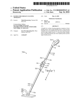
  • 2. Patent Application Publication Sep. 16, 2010 Sheet 1 of 11 US 2010/022931S A1
  • 3. Patent Application Publication Sep. 16, 2010 Sheet 2 of 11 US 2010/022931S A1 Fig.2o.
  • 4. Patent Application Publication Sep. 16, 2010 Sheet 3 of 11 US 2010/022931S A1 eo fieuRe 2c. s
  • 5. Patent Application Publication Sep. 16, 2010 Sheet 4 of 11 US 2010/022931S A1
  • 6. US 2010/022931S A1Sep. 16, 2010 Sheet 5 of11PatentApplication Publication
  • 7. Patent Application Publication Sep. 16, 2010 Sheet 6 of 11 US 2010/022931S A1
  • 8. PatentApplication Publication Sep. 16, 2010 Sheet 7 of11 US 2010/022931S A1 | 6 5.82 SN Gr N N INN 2.9 s N28 NN N N 34 4-N3 N.222 C Fig.6 21te N sy.Alfo -2'io-22d 2OO 62. -256 52132-36 w th 8 44.27 23É f JS23292 N-- SE 2/3KX) sizzly Sä A.2% 2SO2. 25o 42XSS 234. 'B' 3: 2. 22SNY fe 236 255 238
  • 9. Patent Application Publication Sep. 16, 2010 Sheet 8 of 11 US 2010/022931S A1 Fig.7 W W W 9 M f 222 S. ar eXXX (, EN3x E.
  • 10. Patent Application Publication Sep. 16, 2010 Sheet 9 of 11 US 2010/022931S A1 S. 8
  • 11. Patent Application Publication Sep. 16, 2010 Sheet 10 of 11 US 2010/022931S A1
  • 12. Patent Application Publication Sep. 16, 2010 Sheet 11 of 11 US 2010/022931S A1 2 KAS a AE Yé?av. SXSNNNNNNNNNNX yes a As
  • 13. US 2010/0229315 A1 HANDLE FOR SURFACE CLEANING APPARATUS FIELD OF THE INVENTION 0001. The specification relates to handles for surface cleaning apparatus and Surface cleaning apparatus, such as Sweepers, vacuum cleaner, extractors and the like having SaC. INTRODUCTION 0002 The following is not an admission that anything discussed below is prior art or part ofthe common general knowledge ofpersons skilled in the art. 0003 United States patent application publication 2008/ 0.155774 disclosesa floor sweeping apparatus. Ithasa clean ing headandan elongatehandlehavinga firstportion fixedto the cleaning headata pivotingjoint, and atan outerendby a hingeto a secondelongatehandleportion.A locking mecha nism allows the second portion to be locked in different angular positions relative to the first portion. The locking mechanism can be remotely controlled from the handle por tion. Such designs have also been used in vacuum cleaners wherein air passes through an elongate bendable handle or wand. See forexampleU.S. Pat. No. 6,695,352 and U.S. Ser. No. 12/010,358. SUMMARY 0004. Thefollowing introduction is provided to introduce the reader to the more detailed discussion to follow. The introduction is not intended to limit or define the claims. 0005 According to an aspect of the invention, there is provided a handle for a Surface cleaning apparatus con structedsoastobend,pivotorrotatetoaltertheconfiguration ofthehandle attwo positions alongthe length ofthe handle. An advantage ofthis design is thatthe wand may be foldable in half,e.g., eachjointpivoting900. Preferably, thepivotsare spaced a short distance apart. Such as by a spacer or arm positioned between the two pivot joins. The spacer permits the handle to fold in halfifthe handle has members mounted to anexternal Surfacethereof. Suchasa powercord,an exter nal lockcontrol, a power switch or the like. 0006. Accordingto anaspectoftheinvention,ahandlefor a surface cleaning apparatus. It has a first, or lower, handle portion,andasecond, orupper,handleportion.Thereisafirst pivoting lockable joint provided between the lower handle portion and the upperhandle portion. There is a second piv oting lockablejointbetweenthelowerhandleportionandthe upperhandle portion. 0007 According to another aspect, there is provided a handleforasurfacecleaningapparatus. Ithasafirst,orupper, handleportion atan upperregion ofthehandle,anda second, orlower,handleportionatalowerregion ofthehandle.There is a firstpivotinglockablejoint locatedata mid-region ofthe handle.Thereis also a secondpivotinglockablejointlocated atthe mid-region ofthe handle. 0008 According to another aspect, there is provided a handle forasurface cleaningapparatus. It hasa lowerhandle portion and an upperhandle portion. There is a first pivoting lockable joint that allows the lower handle portion and the upperhandleportiontopivotwith respecttoeachother.There is also a second pivoting lockablejointthat allows the lower handle portion and the upper handle portion to pivot with respectto each other. Sep. 16, 2010 0009. In some examples, a single actuator is provided to unlockeachjoint. Preferably, oneofthejoints, preferably the upper one, has two locks, namely a first that comprises lock thatcannotbeovercomebyapplyingforcetothelockwithout breaking to lock, and a second that can be released by the application offorce withoutbreaking the lock. The first may comprisea lockthatis received in a rotatable memberorthat comprisesfirstandsecondinterlockingmembersprovidedon each side ofa pivot joint. The second may be a friction or detent lock. An advantage ofthis design is that a user may operate an actuator to release the locks. The first lock may then rotate freely. Ifit is desired to further bend the handle, Such as to put the Surface cleaning apparatus in Storage, the usermay apply forceateach distal opposedend ofthehandle to bend the handle in halfwithout having to push any more buttons to release a lock. 0010. In some example, the actuatororactuators are pro vided on an upperend ofthe hand and preferably adjacent a handgrip portion. DRAWINGS 0011 Certainexamples willbedescribedin relation to the drawings in which: 0012 FIG. 1 is a perspective illustration ofan example of a surface cleaning apparatus in an upright-in-use configura tion; 0013 FIG. 2a is a perspective illustration ofthe surface cleaning apparatus ofFIG. 1 in a bent configuration; 0014 FIG.2b is a side view ofthe surface cleaningappa ratus ofFIG.2a in a reciprocally advancedorextended posi tion for cleaning under an obstacle; 0015 FIG.2c isa side view ofthe surfacecleaningappa ratus of FIG.2b in a reciprocally retracted position; 0016 FIG. 3 is a perspective illustration of the surface cleaning apparatus ofFIG. 1 in a storage configuration; 0017 FIG. 4 is an exploded view ofa coupling assembly ofthe Surface cleaning apparatus ofFIG. 1; (0018 FIG. 5isacross sectiontakenalongline5-5in FIG. 1; 0019 FIG. 6 isacross section takenalong line 6-6 in FIG. 2: 0020 3: 0021 FIG. 8 is a perspective illustration of an alternate exampleofaSurfacecleaningapparatus inan upright-in-use FIG. 7is across section takenalongline 7-7 in FIG. configuration; (0022 FIG.9 isacross sectiontakenalongline9-9 in FIG. 8 0023 FIG. 10 is a cross section taken along line 9-9 in FIG. 8, showing the Surface cleaning apparatus in a bent-in use configuration. DESCRIPTION OF VARIOUS EXAMPLES 0024. Various apparatus or methods will be described below to provide an example ofeach claimed invention. No example described below limits any claimed invention and any claimed invention may coverprocesses orapparatus that are not described below. The claimed inventions are not lim itedto apparatus orprocesses havingallofthefeatures ofany oneapparatus orprocess describedbelow orto features com mon to multiple orall ofthe apparatus described below. It is possible that an apparatus or process described below is not an embodiment ofany claimed invention.
  • 14. US 2010/0229315 A1 0025. Examples disclosed herein provide a handle for a Surface cleaning apparatus. Such as a Sweeper, which can be used in multiple configurations. For example, thehandle can beconfiguredin an uprightin-use configuration, in which the Surface cleaning apparatus may be used for normal Surface cleaning operations, such as Sweeping a floor. Alternatively the handle can be position in a bent configuration, Such as may permit the cleaning apparatus to be used reach less accessiblesurfaces,suchaswhenSweepingunderfurnitureor the like. Further, the handle can be moved to a storage con figuration, in which the handle is folded in half, such that the height ofthe apparatus is reduced, as for storage. 0026 Referring to FIGS. 1 to 3, an example ofa surface cleaningapparatus 100 is shown. Surface cleaningapparatus 100 has a surface cleaning head 102 and a handle assembly 104. Intheexample shown, surface cleaningapparatus 100 is a Sweeper. Accordingly, Surface cleaning head 102 is oper able to sweepa surfaceand to collectdirttherefrom. In other examples, Surface cleaning apparatus 100 may be a type of Surface cleaning apparatus, suchasa mop,a vacuum cleaner, a steamer, a carpet pick or other like device. 0027. It may help to define a frame of reference with respect to the handles and handle components discussed herein. As shown in FIG. 1, handle assembly 104 has the orientation ofa straight, or Substantially straight, shaft. The shaft defines a lengthwise, or longitudinal, oraxial direction that runs, or extends, from an hand grip 106 at which a user may grasp or manipulate the apparatus, to the cleaning head 102.Theaxial direction mayalsobe notionally designatedas the x-axis. Handle assembly 104 is joined, or operatively connected to, cleaning head 102 ata forcetransfer interface, orjoint, indicated generally as 108. Force transfer interface 108may haveat least a first degreeoffreedom, that degreeof freedom being a rotational degree of freedom permitting cleaning head to pivot about an axis normal to the axial direction of the handle assembly, notionally indicated as a y-axis. Quite typically the force transfer interface may have more than one degree offreedom, the second degree offree dom also beingarotational degreeoffreedom aboutasecond axis perpendicularto the shaft, and commonly mutually per pendicular to the axis of the first degree of freedom. That second axis may be notionally identifiedasa Z-axis. The end joint may bea universaljoint, oraspherical balljointprovid ing both azimuth and horizontal rotational degrees of free dom.The terminology“proximate” and“distal may takethe hand grip 106 as theirorigin orpoint ofreference, andpoints along the path ofthe handle assembly, whatever its configu ration, may be seen in that light. The terms “upward' and "downward' and such like are at least to some extent arbi trary, since the cleaner may be used in the customary orien tation working on flooring, or, perhaps less commonly, against walls, as may be. 0028. In the example at hand, handle assembly 104 has a first,orupperportion 110,andasecond,orlowerportion 112. Firstportion 110hasafirst,orupper,end 114andasecond, or lower, end 116. Similarly second portion 112 has a first or upper end 118 and a second, or lower, end 120. At first end 114 of first portion 110 there is a force transfer interface, which may be an input force transfer interface, and which may beidentifiedas ahandgrab, orhandle, orhandgrip 106. This force transfer interface, or grip, 106 is one at which a moment couple may be imparted to first handle portion 110. Second end 116 of first handle portion 110 is mechanically connectedto firstend 118ofsecondhandleportion 112 at, or Sep. 16, 2010 by,a force and motiontransfer interfaceassembly or module indicated generally as intermediate connection 130. Second end 120 ofsecond portion 112 is connected to cleaning head 102 as indicated above. 0029 Intermediate connection 130 is a force and motion transmissionassembly havingan inputinterface 122., namely thefittingorconnectionatwhichitisconnectedtofirsthandle portion 110,andanoutputinterface 124, namely thefittingor connection at which it is connected to second, or lower, handle portion 112. Between input interface 122 and output interface 124 intermediateconnection 130 has a first lockable joint 140 anda secondlockablejoint142. In theembodiment shown first lockable joint 140 is arbitrarily identified as the proximal, or upper, lockable joint, and lockablejoint 142 is likewise the distal, orlower, lockablejoint located nearer to cleaning head 102. 0030. In the example shown, lower end 120 of lower handle portion 112 is mounted to joint 126 offorce transfer interface 108. Handleassembly 104 is usableto move surface cleaninghead102 alongaSurface,andispivotally mountedto surface cleaninghead 102 atjoint 126. Joint 126 may beany pivoting joint known in the art. Joint 126 allows handle assembly 104 to pivot with respect to surface cleaning head 102atleastaboutafirstaxis,typicallyacross-wise, ory-axis. Insomeembodimentsjoint106 mayalsoallowhandleassem bly 104 to pivot with respect to surface cleaning head 102 about the Substantially vertical or Z-axis, mutually perpen dicular to the y-axis and the X-axis. 0031. Asnotedhereinbelow,handleassembly 104is mov able Such thatSurface cleaningapparatus 100 may beused in a plurality of configurations. For example, FIG. 1 shows handle 104 in an “upright” configuration in which handle assembly 104isgenerally straightand Surfacecleaningappa ratus 100 is usable, for example, for general cleaning. The term “upright' isa termofart. It implies the use ofa substan tially rigid handle assembly that is operated by a user in a standing position, the handle being held predominantly upwardly ofthecleaninghead. Fora shorterpersontheangle will be shallowerthan fora taller person, and the angle may notbegreaterthan45 degrees,although it will mostprobably begreaterthan30degreesupwardfrom horizontal. “Upright' implies operation in the manner of a mop, with the handle assembly functioning predominantly as a strut in compres sionortensiontopushorpulltheworkinghead,e.g.,cleaning head 102. 0032. In this first, or locked, mode, intermediate connec tion 130 has no degree of freedom between input 122 and output 124. That is to say, in this first or locked mode both joints 140 and 142 are locked and intermediate connection 130 locks the position ofportion 110 relative to portion 112, Such thattheentireassemblyconstitutes arigidstrut fromthe input interface at hand grip 102 to the output interface at cleaning head 102. 0033 FIGS. 2a, 2b and 2c show handle assembly 104 ina bentconfiguration,inwhichlowerjointA64ofhandleassem bly 104 is bent, such as may be usable, for example, for cleaning underfurniture, orotherplaces oflesseraccessibil ity. In this second, or partially unlocked, mode intermediate connection, one ofjoints 140 or 142 has a single degree of freedom, that degree offreedom beinga rotational degree of freedom. In this mode while the handle assembly is rigid in the y-direction, and is consequently capable of passing a bendingmomentabouttheZ-directionacrossjointboth upper and lowerjoints 140 and 142, and the knuckle 144 joining
  • 15. US 2010/0229315 A1 them,joint 142, being the lowerjoint, is not capable ofpass ingabending momentaboutthey-direction,andiscapableof deflection about the y-axis. The physical significance ofthis maybeunderstoodby consideringtheprospectofpassingthe cleaning head under a coffee table or under a chair. Upper handle portion 110 may be held such that it extends down wardlyfromtheuser'shandatsomelevelandangle.Thelevel of cleaning head 102 will be dictated by the level of the Surface to be cleaned, constraining motion ofcleaning head 102toaplane. Firsthandleportion 110hasalength fromgrip to the center of rotation of the first joint of Lo. Second handle portion 112 hasa length from the centerofrotation of the secondjoint to the pivot connection to the cleaning head ofL.Thelength ofthelink, orlug,ofconnectionassembly 130 between the centers ofrotation ofjoints 140 and 142 is identified as Lo. In the second mode ofoperation, the link (i.e.,intermediateconnection 130)isalignedwithandfixedin a rigidposition with respect to first handle portion 110, such that the length from the grip to the center of rotation ofthe second joint is merely the Sum of Lo-Lo. Provided that grip 106 isheldataheightthatis suitably lessthanthe sum of Lo-Lo-La, which is, ofcourse, the total rigid length of handle assembly 104 in the first or locked mode, second handle portion 112 will find theappropriateangleofdeclina tion or dip, orazimuth angle, as it may be called. That is, its position is still uniquely determinate. To the extent that the interface at the cleaning head has azimuth and horizontal angular degrees of freedom, but not a torsional degree of freedom,a torsional twistoffirsthandleportion 110 will still betransmittedtocleaninghead 102, allowing ittobe steered. Similarly, since lowerjoint 142 is rigid about the Z-axis, the users can Sweep cleaning head 102 sideways, i.e., circumfer entially relative to grip 106. 0034 Second joint 142 may have a range of motion in which it is substantially free to deflect from the rigid orien tation. In one embodimentthat angularrange ofmotion may be from 0 degrees (i.e., the locked or straight orientation) to perhaps as much as about 90 to 120 degrees from straight. Whiletherigidorientationoffirstandsecondhandleportions 110and112maybeinaxialalignment,itneednotnecessarily be so, but could be a dog-leg or dihedral angle as may be. In any case, onceunlocked,theremaybeafreerange ofmotion. A rigid handle, or handle assembly may be problematic in terms ofcleaning undera chairortable, forexample, requir ingtheuserto lowerthehandlenearerto floorlevel. This may necessitatebending oftheback. Bycontrast,ajointedhandle, as shown and described, can be operated with the second handle portion 112 at or near a condition parallel to the surface to be cleaned, be it a floor or carpet, or at a shallow angle theta with respect thereto (shallow being in the range ofperhaps 0 to 30 degrees from horizontal) while the first, orupperportion ofthehandle 140 isoperatedin a much more steeply angled orientation theta in the range of30 or45 degreesfrom thehorizontal to vertical orperhaps some whatpastverticali.e.,tothepointatwhichtheincludedangle alphabetween first and second handle portions A30 and 110isacuteasinFIG.2c,ratherthanobtuseasin FIG.2b. Note that alpha+(theta-theta)-180. The user may then impart a motion having a significant or pre dominantcomponentofrotationaboutthey-axis atgrip 106. e.g., by flexing the wrist forward and backward, to produce Somethingofapivotingrotational motionofsecondjoint142, with second handle portion 110 functioning as a connecting rod betweenjoint 142 and cleaninghead 102. This may per Sep. 16, 2010 mit the user to use a pivoting wrist or short arm motion to causethecleanertoreciprocateoverthefloor,asSuggestedby double headed arrow A, underneath obstructions such as chairs, beds and tables, symbolized in FIGS. 2b and 2c by table 'T',withoutnecessarilyundulybendingtheuser'sback. 0035 FIG. 3 shows handle assembly 104 in a storage configuration, in which handle assembly 104 is folded over Such that Surface cleaningapparatus 100 is morecompact, as for storage or transport. At the end ofthe angular range of motion discussed above, further deflection of second joint 142, does not occur, because it has reached the end of the range of travel. On application of a greater torque, as by applying a greaterbending moment aboutthe y-axis at what would otherwise be the end of free travel range, deflection may then be caused in the otherjoint, namely firstjoint 140, permittingathird modeofdeflection, namely thatofFIG.3 in which theleg is bentbackupon itself, with a rightangle bend in joint 140, and another right angle bend in joint 142 such that secondportion 112 reverses, and lies beside first portion 110, and handle grip 106 is brought to a position generally nearoradjacentto cleaninghead 102. Theresulting configu ration may be considered a folded, storage or shipment con figuration. 0036 Referringstill to FIGS. 1 to3,handleassembly 104, as noted, hasa first orupperhandleportion 110 andasecond or lower handle portion 112. Each of the first and second handleportions 112 and 114 iselongate. Portions112and114 may be of similar length and shape. In alternate examples, portion 112 and portion 114 may be ofdifferent shapes and lengths. Upper portion 112 and lowerportion 114 may be of Suitable cross-section for transmitting a bending moment. Suitable second moments of area may be obtained for example with a channel or closed section, one Such closed section being a hollow cylindrical tubular section. These components may be made ofmetal materials such as alumi num, Steel, (which may be stainless steel) orplastics such as moulded plastic, which may be fibre reinforced composites. In one embodiment portions 110 and 112 may be hollow aluminum extrusions ofconstant cross-section. Portions 110 and 112 may be ofthe same, orSubstantially the same cross section. 0037 Lowerhandleportion 112 and upperhandleportion 114 are pivotal with respect to each other to provide the plurality of configurations shown in FIGS. 1 to 3. In the example shown, lowerhandle portion 112 is pivotal about a firsty-axis,namelythatofjoint142,andupperhandleportion 110 ispivotalabouta secondy-axis, namely thatofjoint 140, which is parallel to axis 101. Forexample, when handle 104 is in the upright-in-use configuration shown in FIG. 1, lower handleportion 112 andupperhandleportion 110 may tendto be substantially co-axial, or parallel. For example, lower handleportion 112 and upperhandleportion may beata first angle (which may be expressed conveniently in degrees as 180-alpha-2) ofabout 0 to 15 degrees with respect to each other. Intheexampleshown in FIG. 1, thisangleisabout 0 degrees. 0038. Whenhandle 104 is in thebentconfiguration shown in FIGS. 2a, 2b, and 2c lower handle portion 112 and upper handle portion 110 are at a second, different, angle with respectto each other.Thatangle (again,as 180-alpha) ofabout 15 degrees toabout 105or 120degrees toeachother. In theexample shown it is 90degrees. When handle 104is in the storage configuration shown in FIG. 3, lowerhandlepor tion 112 and upper handle portion 110 are at a third, again
  • 16. US 2010/0229315 A1 different angle with respect to each other. That third angle may be at between about 105 or 120 degrees and about 180 degrees. In the example shown that angle is roughly 180 degrees. 0039. In theexample shown, intermediateconnection 130 may have the form ofa coupling assembly 128 provided to link upper and lower portions 110, 112 ofhandle assembly 104. Coupling assembly 128 includes firstand second pivot inglockablejoints 140,142,and is mountedtoupperend 118 of lower handle portion 112 and lower end 116 of upper handle portion 110. Accordingly, pivoting lockable joints 140, 142 are between handle portions 110 and 112, at a mid-region of handle assembly 104. Alternatively, one or both offirstandsecondpivotinglockablejoints 140,142 may be integral with either lower handle portion 112 or upper handle portion 114. In Such examples, the pivoting lockable joints may not be between lower handle portion 112 and upperhandle portion 110. 0040 First and second pivoting lockable joints 140, 142 eachallowlowerhandleportion 112andupperhandleportion 110topivotwith respect toeach other,and further,are releas ably lockable. That is, in the example shown, the lockable joints are lockable such that handle assembly 104 may be locked in the “upright', or Substantially straight, or rigid, configuration ofFIG.1. When second pivoting lockablejoint 142 is unlocked, the handle assembly may be reconfigured into the bent configuration as shown in any ofFIGS. 2a, 2b and2c.Whenfirstpivotinglockablejoint 140isunlocked,the handle may be reconfigured into the fully folded storage or transport configuration. 0041 Referring now to FIG. 4, intermediate connection 130 may also be referred to as a coupling assembly 128. Couplingassembly 128hasa centralassembly, orlink,orlug, identified generally as central assembly 132, to which are mounted first and second connection members, or seats, or Sockets, or fittings, or connection interface members, identi fiedas upperandlowerarms 134and 136 respectively. Lower andupperarms 136and134 definethesocketsorconnections towhichtherespectivematingendsoffirstandsecondhandle portions 112 and 110 are mated. These connections are moment connections (i.e., both lateral shear loads and bend ing moments may be passed across the connections). 0042. The frame, or skeleton, or shell, or casing of the connector link central assembly 132, identified as body 138, includes a pair of mating first and second back shell halves 146, 148 that, when mated togetherdefine an hollow internal cavity, indicated generally as 150. Back shellhalves 146and 148 each have first and second generally rounded end por tions 152, 154 andan intermediate orinterstitial portion 156 intermediate those end portions. Rounded end portions 152, 154 each have a generally circular flange or face 158, 160 extendinginanX-Zplane,andadependingperipheral curtain, or skirt, or wall 162 that has portions extending about the periphery ofthe circularfaces, with thatperipheral wall hav ing a straight or tangential portion 164. Such that the curtain wallrunsalongoneedgefromendtoend.Whenthebackshell halves 146, 148 are brought together the distal edges ofthe respectiveperipheral curtain walls 162 abut, leaving thehol low internal space, namely cavity 150, which, at the ends, extends between two parallel circular planar walls, 158, or 160, as may be. When mated together, the circular walls or faces 158, 160 have mutually alignedcentral bores 166, 168. The hollow circular end portions that result from the mating Sep. 16, 2010 ofthe two backshell halves define lugs, or arms, or toes, or tongues that are identified as first and second wing members 17O and 172. 0043. The resultant peripheral wall has communication Sockets, ports, accommodations or apertures 174, 176 at respective opposite ends thereof, 174 being arbitrarily iden tified as the upper aperture, and 176 being arbitrarily identi fiedastheloweraperture. Theaperturesshown are foursided rectangular openings. They could as easily be round, or half round, orany other Suitable shape. The through thickness of the body is thickest overthe central interstitial portions 156. 0044 Upper and lower arms 134 and 136 each have the general form ofa clevis. Oneend, be ita first end, ofeach of arms 134and 136 is definedby a rootorshank 180 that has a central bore 182 for receiving a respective end ofone or the other ofportions 110and 112. Shank 180 terminatesata pair ofsubstantially circular ears or circular walls 178, 182 that define the other end ofarms 130 and 134, as may be. Those earsorflangesorwalls178,182aresubstantiallyplanarinx-Z planes, and are spaced apart in the y-direction, and have Substantially circular, parallel planar Surfaces that define between them a central rebate or accommodation, indicated generally as 184, into which may be locateda corresponding one ofthe end portions 170 or 172 ofcentral body assembly 132. That is, the second end of each of arms 134, 136 is bifurcated and receives a tongue, in the form of one ofthe rounded ends ofthe body 128 ofthe central link identified as wingmembers170and172.Wingmembers 170and 172have respectivebores 186,188thatalign on installationwith bores 166, 168. A pin, or a pair of threaded mutually engagable hardware fittings, such as a close fitting Chicago Screw and bolt, passes through bores 186, 166, 168 and 188 in the y-direction, and forms the axle ofthejoint. 0045. In summary, lower arm 136 has a first end and a secondend.Thefirstend is mountable totheupperend118of the lower handle portion 112. The first end ofthe lower arm 130 has a blind bore, or accommodation, or socket 192 into which upperend 118oflowerhandleportion 112 is received. The two parts then have the interfitting relationship ofmale and female members. The relationship may be reversed: it is arbitrary whichofthe two is the male member,andwhich the femalemember. Upperend 118may besecured in socket 192 in any Suitable manner, Such as by the use of adhesives, mechanical connectors such as screws, or friction. In some examples,upperend118is removablyreceivedinsocket 192. A releasable detent may be provided, as at 194. Similar to lowerarm 136,upperarm 134hasafirstendandasecondend. In the example shown, the first end of upper arm 134 has a socket 196 intowhich lowerend 116 ofupperhandleportion 110 is received. Lowerend 116 may be secured in socket 196 in any Suitable manner, Such as by the use of adhesives, mechanical connectors such as screws, or friction. In some examples,lowerend116 is removablyreceivedinsocket 196, and may include a releasable detent 194. The geometry of upper arm 134 and the geometric relationship ofupper arm 134to lowerend116 ofupperhandleportion 110, may bethe same, orsubstantially the same, as thatoflowerarm 136 and its relationship to upperend 118oflowerhandleportion 112. 0046 Expressed slightly differently, the second or upper end of lower arm 136 is pivotally mounted to the central assembly132toformsecondpivotinglockablejoint142.The second end oflower arm 136 has first and second opposed circular flanges (i.e., walls 178, 182), and a gap, accommo dation 184, therebetween. Central assembly 132 has a lower
  • 17.
  • 18. US 2010/0229315 A1 applied between lowerhandle portion 112 and upperhandle portion 110 will result in pivoting motion oflower lockable joint 142 as the path ofleast resistance. 0052. When lower arm 136 has pivoted to its full extent, forexampleby 90 degrees as shown in FIG. 6, such that dog 208ofendportion 172 meetsthe mostclockwise, second,end of the guide slot, aperture 202, (and dog 208 bears against abutment 252, causing shoulder 250 to be held in its full travel,bottomedpositionagainstthebackofsocket234),any additional force or moment applied between lower handle portion 112 and upper handle portion 110 will cause the secondguidepin, namely dog208ofendportion 170 to push against abutment edge 262. When enough force is applied to overcomethebiasingforceofsprings264,266,pivotarm258 will movecounter-clockwiseas viewed in FIG. 5, permitting dog208 to movepasttheabutmentedge232towards themost counter-clockwise,secondendoftheguideslot,aperture 200, allowing upper arm 134 to pivot counter-clockwise about pivot pin 190 and thus to permit upper handleportion 110 to move to the storage or transport configuration. Counter clockwise motion is prevented both by dog 208 and by an externalabutmentinthe natureofskirtextension270ofupper arm 234.Accordingly, thethird lockis unlockedby theappli cation of force, and the second pivoting lockable joint is unlocked both by activating actuator 210 and by applying adequate force (or moment, really) to; the second pivoting lockable joint 142. 0053 Arm 258has acam256, which mayextend into slot 200 when clockwise motion ofarm 258 is not obstructed by the presence of dog 208. When handle assembly 104 is returned from thestorageconfigurationofFIG.3 to eitherthe bent configuration of FIGS. 2a, 2b or 2c, or to the initial, straight configuration of FIG. 1, actuator 210 need not be activated, as neithertooth 226 nortooth 228 is engaged when the joints are deflected. On return, dog 208 runs along the more gently oblique back of cam 256, and, in due course, Snaps back into its initial position, and locks, as joint 140 is straightened second pin 214 is held in the unlocked position by cam 238 when thehandle is in the bent-in-use configura tion. 0054) Inthepositionillustratedin FIGS. 1 and5,tooth226 is in its initial or first or home position protruding through aperture 174 and into socket 196, thereby locking upper handleportion 110 andthelink, connectorassembly 130, in a fixed angularorientation to each other, notionally straight. In this condition, upperjoint 140 cannotpivot.Atthe sametime detent member 230 protrudes into socket 234, thereby lock ing lower handle portion 112 in position relative to central portion A130. In this condition, lowerjoint 142 also cannot pivot. 0055 Forward motion ofactuator 210 may then tend to urge push rod 214 forward, which may urge fitting 218 for ward to work againstthe signal receiving member, i.e.,tooth 226, of push rod 222 of transmission member 220. In so doing, the resistance of return spring 244 is overcome, and member226 moves from its initialorfirstpositionprotruding through aperture 174 to a less protruding position. As this occurs,theoutputlug,tooth228,bearsagainstdetentmember 230,overcomes theresistantofspring232,andurges member 230axially downward, clearofsocket234. This motion ends when shoulder 250 of pushrod 222 bottoms out, and the release assembly reaches the end oftravel condition. At this point detent member 230 has been forced to a sufficiently retractedposition thatit isclearofsocket 192,andarm 136 is Sep. 16, 2010 able to pivot in the clockwise direction of Arrow B (as shown in FIG. 5) about the center ofrotation defined by pin 190. Both dog 208 and a skirt or housing extension 255 prevent motion in the counter-clockwise direction from the initial position shown in FIG. 5. 0056 To recap, the first end, i.e., the clevis, ofupperarm 134 ispivotally mounted to central assembly 132 to form the first pivoting lockable joint 140. In the example shown, the secondendoftheupperarm 134hasfirstandsecondopposed circular flanges, namely clevis wings 178, 182, and a gap, namely accommodation 184, therebetween. Central assem bly 132 has an upper portion defining a circular tongue, or end, 170, thatis received in accommodation 184. A pivot pin 190 is inserted through the first and second opposed flanges andthetongue.Accordingly,thefirstandsecondflangespivot about thepivotpin 190toallow theupperhandleportion 110 to pivot with respect to the lowerhandleportion 112. 0057 Similarly to the upperendortongue, 170, thelower end 172 has a guide slot defined by co-operating apertures 200,202, which definesanarc.Thatarc mayextendforabout 90 degrees. A guide pin 190 is inserted through the first and second opposed circular flanges, and is seated in the guide slot defined by apertures 202, 200. The guide slot and the guide pin limit the range of motion of the second pivoting lockable joint 126. That is, referring to FIGS. 5 and 6, when thehandleis intheupright-in-useconfiguration andthebent in-useconfiguration, theguidepin 186 abutsafirstend188of theguide slot 184.Accordingly, the lowerarm 130 may only pivot in a direction indicated by arrow A2. Referring to FIG. 7, when the upper arm 134 has been pivoted in the direction indicated by arrow A2 by 90 degrees, the guide pin 184 will abuta secondend 190oftheguideslot 184,to therebyprevent any furtherpivoting. 0058. In the example shown, as each of the guide slots extends for about 90 degrees, the combined total range of motion provided by the first and second pivoting lockable joints is about 180 degrees. However, in alternate examples, guide slots may not be provided, and the range ofmotion of the first and second pivoting lockablejoints may not be lim ited, or may be limited to other, different, ranges ofmotion. 0059. As noted, first and second pivoting lockable joints 140,142are releasably lockable. Referring to FIGS. 5 and 6. the second pivoting lockable joint 142 is lockable by a first lock. The first lock is defined by the relationship of a first aperture176 definedinwalls 162ofbackshellhalves146,148 ofcentralassembly 132,and a secondaperturedefinedbythe mouthofsocket231 inthelowerarm 130,and theplunger, or detent, or pawl, or tooth, or, in effect, lockbolt that is repre sented by detent 230. When the handle is in the upright configuration andthelowerhandleportion 112andthe upper handle portion 110 are generally axially aligned, these aper turesarealigned,as shown in FIG. 5, anddetent 230 isbiased toextendacrosstheSmallgapbetweenthem,andtolockthem against relative motion,justlikea bolt drivenhomein a lock. Spring 232 provides the biasing force. Thus the pin, i.e., detent 230, locks the second pivotinglockablejoint 142, and prevents the lower handle portion 112 from pivoting with respect to the central assembly 132. To unlock the first lock, a movablememberisprovided, namely tooth 228. Itis biased in a first position, shown in FIG. 5, and is movable between that first position and a second position, shown in FIG. 6. When the first movable member, tooth 228, is moved to the second position it engages, i.e., contacts, the first pin, i.e., detent, 230,andpushes itinopposition tothebiasing force of
  • 19. US 2010/0229315 A1 spring 232, thereby sliding the first pin out ofaperture 176, and removed, unlocking the first or lower lock. 0060. The first or upper pivoting lockable joint 140 is lockablebya secondlockandbyathird lock.Thesecondlock is defined by a third aperture, namely aperture 174 in the flangeorwall 162ofthebackshellhalvesofcentralassembly 132, by a fourth aperture, namely the mouth of socket 219 definedintheupperarm134,andtooth226 which,likedetent 230, whethertermedapin, pawl,stop,abutment,oranyother like name, functions not only as the signal and force trans mittingdevice, butalso as the slidable bolt in thelock. When handle assembly 104 is in the upright configuration and the upper handle portion 110 and lower handle portion 112 are generally axially aligned, orwhen handle assembly 104 is in thebent configurationandlowerhandleportion 112hasbeen pivotedwithrespectcentralassembly 132,theseaperturesare aligned, as shown in FIGS. 5 and 6. Spring 246 provides the biasingforcetendingtopushtooth226to theengageposition in which the bolt of the lock is driven home. Accordingly, when handle assembly 104 is in the upright configuration handleportions 112and114aregenerallyaxiallyaligned,the second pin, tooth 226, locks the first or upperpivoting lock able joint 140, and prevents upper handle portion 110 from pivoting with respect to the central assembly 132. Another movable member, plunger 218 is driven to unlockthe first or upper lock. The second movable member, plunger 218, is biased in a first position, shown in FIG. 5, and is movable between the first position and a second position, shown in FIG. 7. When this movable member is moved to its second position, itengages, i.e., contacts,thepin, i.e.,tooth 218,and drives it out ofthe fourth aperture, unlocking that lock and permitting rotational movement ofjoint 140. 0061. To moveboth first movable member, tooth226, and second movable member, tooth 228, handle assembly has a control, namely actuator 210 (FIGS. 1-3). It has a button located amidst on handgrip 106. The button is biased in a non-pushed configuration, and is movable between the non pushedconfigurationandapushed configuration.Thebiasing force may be provided, for example, by a spring, such as springs 248 and 242, or some other spring (not shown). The button is drivingly connectedtoadrivetrain that may include rod 212, that extends through upper handle portion 110. between thebutton and the second removable member, tooth 226. When the button is pushed, the rod pushes the second movable member from the first position to the second posi tion, and the second movable memberpushes the secondpin outofthe fourth aperture to unlock the second lock. Further, when the second movable memberpushes on the second pin, thefirstmovablemembermovestogetherwiththesecondpin, and pushes the first pin out ofaperture 176. Accordingly, in the example shown, when the control is activated, the first lock and the second lock are simultaneously unlocked. 0062. As noted thesecond pivoting lockablejoint is lock ableby the second lockand by a third lock. The third lock is not unlocked by actuator 210. Accordingly, when actuator 210 is moved, the firstandsecondlocksareunlocked, butthe third lock remains locked. As such, when the control is actu ated, the second pivoting lockingjoint 142 is unlocked, and lowerarm 136 maypivotwith respectto thecentralassembly 132, but the first pivoting lockingjoint 140 remains locked, and the upper arm 134 may not pivot with respect to the central assembly 134. 0063. To reconfigure thehandlefrom the storageconfigu rationofFIG.3 backtothebentconfigurationofFIGS. 2a,2b Sep. 16, 2010 and 2c, or the upright configuration ofFIG. 1, force may be applied to pivot the upper handle portion 110 and lower handleportion 112away fromeach other.Whenenough force is applied to the upperhandleportion 110, guide pin 208 will ride against pivotal arm 258 such that it pivots away, and the guide pin, dog 208, will snap back into place between the abutmentedge262andthesecondendoftheguideslotto lock the third lock. Further, when the upperarm portion 110 and the lower arm portion 112 are pivoted back to the upright configuration, detent 230 will snap back into aperture 176, and tooth 226 will snap backinto the fourth aperture defined by the mouth ofsocket 219, to re-lock the first and second locks. 0064. Accordingly,a user may use Surface cleaning appa ratus 100 in the upright configuration. Ifthe user desires to clean a hard to reach Surface, for example a surface under a piece offurniture (e.g., Table T), the user may actuate the control and apply force to pivot lower handle portion about lowerjoint 142 ofcentral assembly 132 and convert surface cleaning apparatus 100 to the bent configuration. In order to revert back to the upright configuration, the user may apply force to pivot lower handle portion 112 backwards until the lock Snaps back into a locked configuration. To convert the Surfacecleaningapparatustoastorageconfiguration,theuser may convert the Surface cleaning apparatus to the bent con figuration, andthen may apply forceto unlockthe thirdlock, and pivot the upper handle portion 114 towards the lower handle portion 112, the moment couple required to pivot secondjoint 142 being less than the moment couple required to overcome the resistance to displacement ofthe third lock inhibiting motion offirstjoint 140. 0065. Analternateexampleofacouplingassembly828is shown in FIGS. 8 to 10. In this example, coupling assembly 828 has only a first lock894and a second lock906. Accord ingly, when thecontrol is actuated, boththe firstlock894and thesecondlock906 are unlocked,and thefirstpivoting lock ablejoint 824 and thesecond pivoting lockablejoint 826are unlocked. Further,in thisexample,guide slotsandguidepins are not provided. Further, inthisexample, opposed sidearms 938,940, areprovided, which providesupportto the first824 and second 826 joints. 0066. In alternateexamples (not shown),acontrol may be provided which unlocks only one lock ofhandle 104, such that only one ofthe first pivoting lockablejoint 124 and the second pivoting lockable joint 126 is unlocked when the control is actuated. Accordingly, a second control may be providedwhich unlocksasecondlock,and optionally,athird control may be provided which unlocks a third lock. 0067. It will beappreciated thatwhilethe design has been exemplified by a handle that does not have air flow there through, the design may be adaptedto ahandle orwand that has air flowing therethrough either by using a rotatable air flowcoupling,suchasdisclosedinU.S. Pat. No. 6,695.352 or a flexible hose as disclosed in U.S. Ser. No. 12/010,358 the disclosure ofeach ofwhich is incorporated herein by refer ence. It will be appreciated that, in Such designs, the pivot joint and the lock for the pivot joint are preferably located exteriortotheairflow passageasexemplifiedinU.S.Ser.No. 12/010,358.
  • 20. US 2010/0229315 A1 1. A handle fora surface cleaning apparatus comprising a) a lowerhandle portion; b) an upper handle portion; c)a firstpivotinglockablejointprovidedbetweenthelower handle portion and the upperhandle portion; and d) a second pivoting lockable joint provided between the lowerhandle portion and the upper handle portion. 2. The handle of claim 1, further comprising a coupling assembly mounted to the lowerhandleportion and the upper handleportion, whereinthecouplingassemblycomprises the firstpivoting lockablejoint andthe second pivoting lockable joint. 3. The handle ofclaim 2, wherein the coupling assembly comprises: a) a central assembly comprising a lower memberportion and an upper memberportion; b)a lowerarm havinga lowerarm firstend mounted to the lowerhandleportion anda lowerarm secondend pivot ally mounted to the lower member portion; and c) an upperarm having an upper arm first end mounted to the upper handle portion and an upper arm second end pivotally mounted to the upper memberportion; wherein the lowermemberportion and the lowerarm second end define the first pivoting lockablejoint; and the upper member portion and the upper arm second end define the second pivoting lockablejoint. 4.Thehandleofclaim3,whereinthefirstpivotinglockable joint is lockable by a first lock, the first lock comprising: a) a first aperture in the lower member portion; b) a second aperture in the lowerarm; and c)a firstpinbiasedto sitinextendbetweenthefirstaperture and the second aperture to prevent rotation ofthe lower arm about the central assembly. 5. Thehandle ofclaim 4, wherein thefirst lockis unlocked by slidingthefirstpin outofthe firstapertureandintosecond aperture. 6. The handle of claim 5, wherein the second pivoting lockable joint is lockable by a second lock, the second lock comprising: a) a third aperture in the upper member portion; b) a fourth aperture in the lowerarm; and c)asecondpinpositionabletositinandextendbetweenthe thirdapertureand thefourthapertureto prevent rotation ofthe upper arm about the central assembly. 7. The handle of claim 6, wherein the second lock is unlocked by sliding the first pin out ofone ofthe third aper ture and the fourth aperture and into the other of the third aperture and the fourth aperture. 8. Thehandleofclaim any ofclaim 7, wherein the second pivoting lockablejoint is furtherlockable by a third lock, the third lock comprising a) a guide pin mounted to the upper arm; and b) an abutment edge in the central assembly and biased againsttheguidepintopreventrotation oftheupperarm about the central assembly. 9. The handle of claim 8, further comprising a control configured to simultaneously unlock the first lock and the secondlockwhenactuated,whereinthethirdlockisunlocked by theapplication offorce to the third lock. 10. The handle ofclaim 1, wherein the firstpivoting lock able joint and the second pivoting lockable joint each com prise a first lock, and the handle further comprises a control configured to simultaneously unlock each of the first locks when actuated. Sep. 16, 2010 11.Thehandleofclaim 10,whereinoneofthefirstpivoting lockable joint and the second pivoting lockable joint com prises a second lock, wherein the second lock is unlocked at least by the application offorce. 12. The handle of claim 1, further comprising a control configured to unlock one ofthe first pivoting lockable joint and the second pivoting lockablejoint when actuated. 13. The handle ofclaim 12, wherein the other ofthe first pivotinglockablejointandthesecondpivotinglockablejoint is unlocked at least by the application offorce. 14. The handle ofclaim 9, wherein: a) a handgrip is mounted to the upper handle portion; and b) the control is provided on the handgrip. 15. The handle ofclaim 1, wherein: a) the first pivoting lockable joint allows the handle to be reconfigured from an upright-in-use configuration to a bent-in-use configuration; and b) the second pivoting lockablejoint allows the handle to be reconfigured from the bent-in-use configuration to a storage configuration. 16.The handle ofclaim 1, wherein the firstpivoting lock ablejoint is provided adjacent the lowerhandle portion, and the second pivoting lockable joint is provided adjacent the upperhandle portion. 17.The handle ofclaim 1, wherein the firstpivoting lock ablejointandthesecondpivotinglockablejointprovidea 180 degree range ofmovementbetween the lowerhandle portion and the upperhandle portion. 18. The handle ofclaim 1, wherein the lower handle por tion and the upper handle portion are pivotal about parallel aXCS. 19. A handle fora Surface cleaning apparatus comprising a) a lowerhandleportion at a lower region ofthe handle; b)an upperhandleportionatanupperregionofthehandle; c) a first pivoting lockable joint at a mid-region of the handle; and d)asecondpivotinglockablejointatthe mid-region ofthe handle. 20. The handle ofclaim 19, further comprising a control configured to unlock one ofthe first pivoting lockable joint and the second pivoting lockable joint when actuated, wherein the other ofthe first pivoting lockablejoint and the second pivoting lockable joint is unlocked at least by the application offorce. 21. The handle ofclaim 19, wherein: a) the first pivoting lockable joint allows the handle to be reconfigured from an upright-in-use configuration to a bent-in-use configuration; and b) the second pivoting lockablejoint allows the handle to be reconfigured from the bent-in-use configuration to a storage configuration. 22.Thehandleofclaim 19, wherein firstpivoting lockable joint and the second pivoting lockable joint provide a 180 degree range ofmovementbetween the lowerhandle portion and the upperhandle portion. 23. The handle ofclaim 19 wherein the upperhandle por tion and lowerhandle portion arepivotal about parallel axes. 24. A handle fora Surface cleaning apparatus comprising a) a lowerhandleportion; b) an upper handle portion; c) a firstpivoting lockablejoint allowing the lowerhandle portion and the upper handle portion to pivot with respect to each other, and
  • 21. US 2010/0229315 A1 d) a second pivoting lockable joint allowing the lower handleportionandtheupperhandleportiontopivotwith respect to each other. 25. The handle ofclaim 24, further comprising a control configured to unlock one ofthe first pivoting lockable joint and the second pivoting lockable joint when actuated, wherein the other ofthe first pivoting lockable joint and the second pivoting lockable joint is unlocked at least by the application offorce. 26. The handle ofclaim 24, wherein: a) the first pivoting lockablejoint allows the handle to be reconfigured from an upright-in-use configuration to a bent-in-use configuration; and b) the second pivoting lockablejoint allows the handle to be reconfigured from the bent-in-use configuration to a storage configuration. 27.Thehandleofclaim 24, wherein firstpivoting lockable joint and the second pivoting lockable joint provide a 180 degreerange ofmovementbetween the lowerhandle portion and the upperhandle portion. Sep. 16, 2010 28. The handle ofclaim 24 wherein the upperhandle por tion and the lower handle portion are pivotal about parallel aXCS. 29. A Surface cleaning apparatus comprising: a) a Surface cleaning head; b) a lower handle portion having a lower handle portion firstendandalongitudinally opposedlowerhandlepor tion second end, the lowerhandle portion first end piv otally mounted to the Surface cleaning head; c) an upperhandleportion havingan upperhandleportion firstendandalongitudinally opposedupperhandlepor tion second end; d) a first pivoting lockable joint provided between the lower handle portion second end and the upper handle portion first end; and e) a second pivoting lockable joint provided between the lower handle portion second end and the upper handle portion first end.