SlideShare a Scribd company logo
1 of 15
Download to read offline
THELETTERETUTTAA ANIMATIONUS 20180230913A1
(19)United States
(12)Patent Application Publication (10)Pub.No.:US2018/0230913 A1
Clark et al. (43) Pub. Date: Aug. 16, 2018
(54) PRESSURE SENSOR ASSEMBLY FOR ATURBINE ENGINE
(52) U.S. CI.CPC ............ F02C 9/24 (2013.01); F23N 2025/04
(2013.01); GOIL 9/008 (2013.01); GOIL
9/0076 (2013.01)(71) Applicant: General Electric Company,
Schenectady,NY (US)
(57) ABSTRACT(72) Inventors: RobertArthur Clark, Cincinnati,OH
(US); Hejie Li,Mason,OH (US);
Mark Rosenzweig, West Chester, OH
(US); K ’Ehleyr James, Sharonville,
OH (US); Jorge Camacho, Queretaro
(MX);Keith F .Beatty ,Cincinnati, OH
(US); Joshua Friedman, Jacksonville
Beach, FL (US)
(21) Appl.No.: 15/429,573
A gas turbine engine includes a liner positioned within a
compressorsection or a turbine section of the gas turbine
engine and at least partially defining a core air flowpath
through the gas turbine engine. The gas turbine engine also
includes a casing at least partially enclosing the liner.
Additionally, the gas turbine engine includes a pressure
sensorassembly having a body,an extension member,and a
pressure sensor. The pressure sensor is positioned at least
partially within the body and the body is positioned at least
partially on an outer side of the casing, the extension
member extending from thebody through a casing opening
in the casing and towards a liner opening in the liner. The
extension member defines a continuous sense cavity expos
ing the pressure sensor to the core air flowpath .
(22) Filed: Feb. 10,2017
(51)
Publication Classification
Int. Ci.
F02C 9/24 (2006.01)
GOIL 9/00 (2006.01)
7810
-54Xudover
by 76
62 --
-
-
www : --
--
ho--
annannarnannananna --
4449 3430 12R
a tervvvvvvwvVAM
wanananananana wergh baki
?
?
?
?
?
3027 74 322
--- - - - - -
46
62
persona78
10
54
Patent Application Publication
wwwwww
58
62-
A
whatthaeuth
when
www
- : E
w
-3636
-34
****
12
*
w
.www
too
mongwwwwwwwwwwwwwwwwwwwwwwwwwwwww
Wwwwwwwwwwwwwwwwwww
-
w
www.
w
wwwwwwwwwwwwwwwwwwwwwwwwwwwwwwwwwww
.
wwww.**
wwwwwwwwwww
persones
WWWWWWWWWWWWWW
D
Aug. 16 , 2018 Sheet 1 of 7
481
40
24
www .
26
18
Zzza
4
74
30
Throughthe
sé
FIG.1
US 2018/0230913 A1
***********************
wwwwwwwwwwwww
US 2018/0230913 A1
901
X
OXOCODO
?????????????????????,
????????????????????????????????20
*XXX**C
KOUSKOOD
201
WWW
DOL
051
/
1
97
www
KMK*
Aug. 16 , 2018 Sheet 2 of 7
La
AKTIVITITIYHTLINYT
ZE
BIL
*******
798
91
WY
COLOS
9
????????????????????????N
G
MG
/ZZZZZZZZZZZZZ952
ZIL
DEKSELZ
ZZZZZZZZI
AR
unded
w
Patent Application Publication
MAALAAAAAAAAAAAAAAAAAAAAAAAAAAAA001
ago
ISI
Patent Application Publication Aug. 16 , 2018 Sheet 3 of 7 US 2018/0230913 A1
w
1
pocco
/
1 w
A
w
wwwwwwwwww
www LALALA
www
1401158 1144
1754
KIAw
- 146175 172
1
zzzz goldings
z zzzz POGODK
Z
SIIIIIIZ
150.
ws
FIG.3
Patent Application Publication Aug. 16 , 2018 Sheet 4 of 7 US 2018/0230913 A1
138L134 WWWWWWWW W
AAAAAAAAA..
.
****
**
Madadadada ****
1500MAS
zsl 150 **
*
9EL *****
**
*
SL001 156 x *
dadadada
ZE 104
2da act
110
801
ZZZZZZZZZZZZZN151/ son
.841
Sen
---150 ook
book
w AcabadookoowoMAMMALALACLAADALLALAAAAAAAAAAAAAAAAAAAAAAA w
wwfr
wwww
poona
DUKKERXXXXXXXXXXXXXXXXXXXXXXXXAAAAAAAAAAAAC 144
AAAAAAAAAAAAAAAAAAA . . . . . . . WAKA * * * * AXXARA*AXAR . AMA
Add oond
w Popco www
** * KERS
1
I
Patent Application Publication Aug. 16 , 2018 Sheet 5 of 7 US 2018/0230913 A1
1
N 184
1
-****-uuuuuu-**--
168 -
****YWwwwwwww
-
1168
-160
-
16221
AY 156 140www158 ) 1445
and7 175 1721 7 2 1
ar 176-1767 S w
ZZZZZZZ
STIILIT150-
Doodnot
FIG.5
Patent Application Publication Aug. 16 , 2018 Sheet 6 of 7 US 2018/0230913 A1
66ond
0 -184****
***
w
*
**********************
****
**
********
*************************
2 -168LLLLSHARELARISTALLAT -160
1
W 156***
158 140 144oonoportetopo
1
ondisshanom 168 175 175 1725 7 12
7176
s 19.ZZZZZZZZZERIEMonks new
b i
180 178
ZZZZZZZZZZZ
LII
1504
SIIIII
108
1non
Facest
Patent Application Publication Aug. 16, 2018 Sheet 7 of 7 US 2018/0230913 A1
WA
...
googad
pocopobo
1521 15 cand152w
www hann
* MWWW.
wwwwwwwwwwww
1bobo
wwww
Penghitung
Boererateand
US 2018/0230913 A1 Aug. 16, 2018
PRESSURE SENSOR ASSEMBLY FOR A
TURBINE ENGINE
FIELD
[0001] Thepresentsubjectmatter relatesgenerally to a gas
turbine engine, or more particularly to a pressure sensor
assembly for a gas turbine engine.
BACKGROUND
[0002] Certain combustors on aircraft engines may be
particularly susceptible to combustion dynamics. Under
certain engine operating conditions, significant transient
pressure waves ( pings”) can be present, particularly in an
annular combustor. These pressure waves, if of sufficient
magnitude, may cause high cycle fatigue of combustor
components, long before the hardware would need to be
replaced under normaloperations.
[0003] One knownapproach to combustor dynamic issues
can involve carefulmapping ofproblem regimes using test
engines with multiple combustor instrumentation pressure
sensors.Aircraft fuel schedulesdeveloped from this process
and subsequently programmed into engine control were
expected to avoid all problem areas.Despite thismapping,
however, subtle differences between engines may still
adversely affect combustion dynamics behavior. These
changes may be due to parameters includingmanufacturing
variations, engine deterioration, fuel composition, or unex
pected flight conditions.
[0004] Therefore, itmaybe beneficialtomonitorcombus
tor dynamics during fielded operation of the gas turbine
engine such that modifications to one or more control
parameters may bemade to reduce the combustor dynamics
in the eventthey progress above a certain threshold.How
ever, it can be difficult to accurately measure combustor
dynamics during operation given the relatively harsh con
ditions within a combustion chamber of the gas turbine
engine.
[0005] Accordingly, features for monitoring combustion
dynamics in aircraft engines are desired. Specifically, fea
tures for more accurately measuring a pressure within a
combustion section of a gas turbine engine would be par
ticularly useful.
casing, the extension member extending from the body
through the casing opening in the casing and towards the
liner opening in the liner, the extension member defining a
continuoussense cavity exposing the pressure sensor to the
core air flowpath .
[0008] In certain exemplary embodiments the liner is an
outer liner of a combustor assembly of the gas turbine
engine, and wherein the casing is a combustor casing .
10009 ] Additionally, in other exemplary embodiments the
pressure sensor includes a diaphragm exposed to the sense
cavity of the extension member, the pressure sensor further
includes piezo-electric material positioned against the dia
phragm opposite the sense cavity.
[0010] Moreover, in certain exemplary embodiments the
pressure sensor includes a diaphragm exposed to the sense
cavity of the extension member, and wherein the pressure
sensor is an optical-based sensor for measuring a deflection
of the diaphragm . For example, in certain exemplary
embodiments the optical-based sensormay include an opti
cal laser directed to the diaphragm .
[0011] Further, in certain exemplary embodiments the
extension memberdefinesone ormore coolingholes located
inward of the casing along the radial direction and outward
of the liner along the radial direction.
[0012] Additionally, in certain exemplary embodiments
the liner includes a ferrule, and the extension member
extends into the ferrule.
[0013] Moreover, in certain exemplary embodiments the
pressure sensor assembly is removably coupled to the cas
ing.
[0014] Further, in certain exemplary embodiments the
pressure sensor assembly further includes a clamp nut,
wherein the clamp nut is removably coupled to the body to
hold the sensor in position.
[0015] Additionally, in certain exemplary embodiments
the gas turbine engine further includes a plurality ofpressure
sensor assemblies arranged along the circumferentialdirec
tion of the gas turbine engine.
[0016] Moreover, in certain exemplary embodiments the
casing opening of the casing and the liner opening of the
liner are each configured as part of a borescope inspection
port.
[0017]. Further, in certain exemplary embodiments the
liner is a liner of a high pressure turbine in the turbine
section of the gas turbine engine, and wherein the casing is
a turbine casing.
[0018] In another exemplary embodiment of the present
disclosure, a pressure sensor assembly is provided for a gas
turbine engine. The gas turbine engine defines a radial
direction and includes a liner at leastpartially defining a core
air flowpath through a compressor section or a turbine
section and a casing at leastpartially enclosing the liner. The
pressure sensor assembly includes a body configured for
positioning adjacent to the casing of the gas turbine engine,
and a pressure sensorpositioned at least partially within the
body. The pressure sensor assembly further includes an
extension member extending from thebody and configured
to extend at least partially through a casing opening in the
casing and towards a lineropening in the liner, the extension
member defining a continuous sense cavity to expose the
pressure sensor to the core air flowpath of the gas turbine
engine.
[0019] In certain exemplary aspects the pressure sensor
includes a diaphragm exposed to the sense cavity of the
BRIEF DESCRIPTION
10006 ] Aspects and advantages ofthe inventionwillbe set
forth in part in the following description, ormay be obvious
from the description,ormaybe learned through practice of
the invention .
[0007] In one exemplary embodimentofthe present dis
closure a gas turbine engine defining a radial direction and
a circumferential direction is provided. The gas turbine
engine includes a liner positioned within a compressor
section or a turbine section of the gas turbineengine and at
least partially defining a core air flowpath through the gas
turbine engine. The liner defines a liner opening. The gas
turbine engine also includes a casing at least partially
enclosing the liner, the casing defining first, inner side along
the radial direction, a second, outer side opposite the first
side, and a casing opening. The gas turbine engine also
includes a pressure sensor assembly comprising a body,an
extension member, and a pressure sensor, the pressure
sensor position at least partially within the body and the
body positioned at least partially on the second side of the
US 2018/0230913 A1 Aug. 16, 2018
extension member, wherein the pressure sensor further
includes piezo-electric materialpositioned against the dia
phragm opposite the sense cavity.
[0020] Additionally,in certain exemplaryaspects thepres
sure sensorincludesa diaphragm exposed to thesense cavity
ofthe extension member,wherein the pressure sensor is an
optical-based sensor for measuring a deflection of the dia
phragm . For example, in certain exemplary aspects the
optical-based sensor includesan opticallaser directed to the
diaphragm .
[0021] Moreover, in certain exemplary aspects the exten
sion member defines one or more cooling holes located
inward of the casing along the radial direction and outward
of the liner along the radial direction when the pressure
sensor assembly is installed in the gas turbine engine.
0022]. Further, in certain exemplary aspects the pressure
sensor assembly is configured to be removably coupled to
the casing.
10023] Additionally, in certain exemplary aspects the pres
sure sensorassembly further comprises a clampnut,wherein
the clamp nutis removably coupled to thebody to hold the
sensor in position.
[0024] Moreover, in certain exemplary aspects the lineris
an outer liner of a combustor assembly of the gas turbine
engine,wherein the casing is a combustor casing.
[0025] These and otherfeatures,aspectsand advantagesof
the present invention will become better understood with
reference to the following description and appended claims.
Theaccompanying drawings, which are incorporated in and
constitute a partofthis specification, illustrate embodiments
ofthe invention and, togetherwith thedescription,serve to
explain the principles of the invention.
DETAILED DESCRIPTION
[0034] Reference will now be made in detail to present
embodiments of the invention, one or more examples of
which are illustrated in the accompanying drawings. The
detaileddescription usesnumerical and letter designationsto
referto features in the drawings.Likeorsimilar designations
in thedrawings and description have been used to refer to
like or similar parts of the invention . As used herein , the
terms “ first" , "second”, and “ third” may be used inter
changeably to distinguish one component from another and
are not intended to signify location or importance of the
individualcomponents. The terms“ forward” and “aft” refer
to relative axial positionswithin a gasturbineengine,with
forward referring to a position closer to an engine inlet and
aft referring to a position closer to an engine nozzle or
exhaust. The terms" upstream " and " downstream ” refer to
the relative direction with respect to fluid flow in a fluid
pathway. For example , " upstream ” refers to the direction
from which the fluid flows, and “downstream ” refers to the
direction to which the fluid flows.
[0035] Referring now to the drawings, wherein identical
numerals indicate the same elements throughoutthe figures,
FIG . 1 is a schematic cross-sectional view of a gas turbine
engine in accordancewith an exemplary embodimentof the
present disclosure.Moreparticularly,forthe embodimentof
FIG . 1, the gas turbine engine is a high-bypass turbofan jet
engine 10, referred to herein as "turbofan engine 10.” As
shown in FIG . 1, the turbofan engine 10 defines an axial
direction A (extending parallel to a longitudinal centerline
12 provided for reference), a radial direction R , and a
circumferential direction (i.e., a direction extending about
the axial direction A ; not depicted).In general,the turbofan
10 includes a fan section 14 and a core turbine engine 16
positioned downstream from the fan section 14 .
[0036] The exemplary core turbine engine 16 depicted
generally includes a substantially tubular outer casing 18
that definesan annular inlet 20. The outer casing 18 encases,
in serial flow relationship,a compressor section including a
booster or low pressure (LP) compressor 22 and a high
pressure (HP) compressor 24; a combustion section 26 ; a
turbine section including a high pressure (HP) turbine 28
and a low pressure (LP) turbine 30, and a jet exhaustnozzle
section 32. A high pressure (HP) shaft or spool34 drivingly
connects theHP turbine 28 to the HP compressor 24. A low
pressure (LP) shaft or spool 36 drivingly connects the LP
turbine 30 to theLP compressor 22. The compressor section,
combustion section 26 , turbine section , and jet exhaust
nozzle section 32 together define a core air flowpath 37
through thecore turbine engine 16.
[0037] For the embodiment depicted, the fan section 14
includes a variable pitch fan 38 having a plurality offan
blades 40 coupled to a disk 42 in a spaced apartmanner.As
depicted, the fan blades 40 extend outwardly from disk 42
generally along theradialdirection R . Each fan blade 40 is
rotatablerelativeto the disk 42 abouta pitch axis P by virtue
ofthe fan blades 40 being operatively coupled to a suitable
actuation member 44 configured to collectively vary the
pitch of the fan blades 40 in unison. The fan blades 40, disk
42, and actuationmember 44 are together rotatable aboutthe
longitudinal axis 12 by LP shaft 36 across a power gearbox
46 . The power gear box 46 includes a plurality of gears for
stepping down the rotational speed of the LP shaft 36 to a
more efficient rotational fan speed .
BRIEF DESCRIPTION OF THE DRAWINGS
[0026 ] A full and enabling disclosureofthepresentinven
tion, including the best mode thereof, directed to one of
ordinary skill in the art, is set forth in the specification,
which makes reference to the appended figures, in which:
[0027] FIG . 1 is a schematic cross-sectionalview of an
exemplary gasturbine engine according to various embodi
ments ofthe present subjectmatter.
[0028] FIG . 2 is a schematic, cross-sectional view of a
combustor assembly and turbine in accordance with an
exemplary embodiment of the present disclosure.
[0029] FIG . 3 is a close up, cross-sectional view of a
pressure sensor assembly in accordance with an exemplary
embodiment of the present disclosure.
[0030] FIG . 4 is a schematic, cross-sectional view of a
combustor assembly and turbine in accordance with another
exemplary embodimentofthe present disclosure.
[0031) FIG . 5 is a close up, cross-sectional view of a
pressure sensorassembly in accordancewith another exem
plary embodiment ofthe present disclosure.
[0032] FIG . 6 is a close up, cross-sectional view of a
pressure sensor assembly in accordance with yet another
exemplary embodiment of the present disclosure.
[0033] FIG . 7 is a schematic,axial view of a combustion
section of the gas turbine engine including a plurality of
pressure sensorassemblies in accordancewith an exemplary
embodiment of the present disclosure.
US 2018/0230913 A1 Aug. 16, 2018
[0038] Referring still to the exemplary embodiment of
FIG . 1, the disk 42 is covered by rotatable front nacelle 48
aerodynamically contoured to promote an airflow through
the plurality of fan blades 40. Additionally, the exemplary
fan section 14 includesan annular fan casing orouter nacelle
50 that circumferentially surroundsthe fan 38 and/oratleast
a portion of the core turbine engine 16 . The nacelle 50 is
supported relative to the core turbine engine 16 by a plurality
of circumferentially-spaced outlet guide vanes 52. More
over,a downstream section 54ofthenacelle 50 extends over
an outerportion of the core turbine engine 16 so as to define
a bypass airflow passage 56 therebetween.
[0039] During operation of the turbofan engine 10, a
volume of air 58 enters the turbofan 10 through an associ
ated inlet 60 ofthe nacelle 50 and/or fan section 14. As the
volume of air 58 passes across the fan blades 40, a first
portion ofthe air 58 asindicated by arrows62 is directed or
routed into the bypass airflow passage 56 and a second
portion of the air 58 as indicated by arrow 64 is directed or
routed into theLP compressor 22. The ratio between the first
portion of air 62 and the second portion of air 64 is
commonly known as a bypass ratio. The pressure of the
second portion of air 64 is then increased as it is routed
through the high pressure (HP) compressor 24 and into the
combustion section 26, where it is mixed with fuel and
burned to provide combustion gases 66.
[0040] The combustion gases 66 are routed from the
combustion section 26 , through the HP turbine 28 where a
portion of thermal and/orkinetic energy from the combus
tion gases 66 is extracted via sequential stages ofHP turbine
stator vanes 68 that are coupled to the outer casing 18 and
HP turbine rotor blades 70 that are coupled to the HP shaft
or spool34, thus causing the HP shaft or spool34 to rotate,
thereby supporting operation of the HP compressor 24. The
combustion gases66 are then routed through the LP turbine
30 where a second portion of thermal and kinetic energy is
extracted from thecombustion gases66 via sequentialstages
of LP turbine stator vanes 72 that are coupled to the outer
casing 18 and LP turbine rotorblades 74 that are coupled to
the LP shaft or spool 36 , thus causing the LP shaft or spool
36 to rotate, thereby supporting operation of the LP com
pressor 22 and/or rotation of the fan 38.
[0041] The combustion gases 66 are subsequently routed
through the jet exhaustnozzle section 32 ofthe core turbine
engine 16 to provide propulsive thrust. Simultaneously, a
pressure of the first portion of air 62 is substantially
increased as the first portion of air62 is routed through the
bypass airflow passage 56 before it is exhausted from a fan
nozzle exhaust section 76 ofthe turbofan 10, also providing
propulsive thrust. The HP turbine 28, theLP turbine 30,and
thejetexhaustnozzle section 32atleast partially define a hot
gaspath 78 for routing the combustion gases 66 through the
core turbine engine 16.
[0042] It should be appreciated ,however, that the exem
plary turbofan engine 10 depicted in FIG . 1 is by way of
example only, and that in other exemplary embodiments, the
turbofan engine 10 may have any other suitable configura
tion. Additionally, or alternatively, aspects of the present
disclosure may be utilizedwith any other suitable aeronau
tical gas turbine engine,such as a turboshaft engine, turbo
prop engine, turbojet engine, etc .Moreover, aspects of the
present disclosure may further be utilized with any other
land-based gas turbine engine, such as a power generation
gasturbineengine,orany aeroderivative gasturbine engine,
such as a nautical gas turbine engine.
[0043] Referring now to FIG . 2, a close-up, side, cross
sectionalview is provided ofa combustor assembly 100 and
turbine in accordance with an exemplary embodimentofthe
presentdisclosure. In at least certain exemplary aspects,the
combustorassembly 100 of FIG . 2 may bepositioned in the
combustion section 26 of the exemplary turbofan engine 10
of FIG . 1, and similarly, the turbine of FIG . 2 may be
positioned in the turbine section ofthe exemplary turbofan
engine 10 of FIG . 1.
[0044] As shown, the combustor assembly 100 generally
includes an inner liner 102 extending between an aftend 104
and a forward end 106 generally along the axial direction A ,
aswell as an outerliner 108 also extending between an aft
end 110 and a forward end 112 generally along the axial
direction A . The inner and outer liners 102, 108 together at
least partially define a combustion chamber 114 therebe
tween. The inner and outer liners 102, 108 are each attached
to or formed integrally with an annular dome. More par
ticularly, the annular dome includes an inner dome section
116 formed integrally with the forward end 106 of the inner
liner 102 and an outer domesection 118 formed generally
with the forward end 112 of the outer liner 108. Further, the
inner and outer dome section 116, 118 may each be formed
integrally (or alternatively may be formed of a plurality of
components attached in any suitablemanner) andmay each
extend along the circumferential direction C (see FIG . 6) to
define an annular shape.
10045 ] For the embodiment depicted, the inner liner 102
and the outer liner 108 are each formed ofa ceramic matrix
composite (CMC)material,which is a non-metallic material
having high temperature capability. Exemplary CMC mate
rials utilized for such liners 102, 108 may include silicon
carbide, silicon, silica or alumina matrix materials and
combinations thereof.However, in other exemplary embodi
ments, oneorboth of the inner liner 102 and outer liner 108
may instead be formed of any other suitable material, such
as a suitable metal material.
[0046] Additionally, it should be appreciated that in other
embodiments, the combustor assembly 100 may not include
the inner and/or outer dome sections 116 , 118;may include
separately formed innerand/orouterdomesections 116, 118
attached to therespective inner liner 102 and outer liner 108;
ormay have any other suitable configuration.
[0047] Referring still to FIG . 2, the combustor assembly
100 further includes a plurality offuelair mixers 124 spaced
along the circumferential direction C (see FIG ., 6 , below )
and positioned at least partially within the annular dome.
More particularly, the plurality of fuel air mixers 124 are
disposed at least partially between the outer dome section
118 and the inner domesection 116 along the radialdirection
R . Compressed air from the compressor section of the
turbofan engine 10 flowsinto or through the fuel air mixers
124,where the compressed airismixed with fuel and ignited
to create the combustion gases 66 within the combustion
chamber 114. The inner and outer dome sections 116, 118
are configured to assist in providing such a flow of com
pressed air from the compressor section into or through the
fuel air mixers 124 . For example, theouter domesection 118
includes an outer cowl 126 at a forward end and the inner
dome section 116 similarly includes an inner cowl 130 at a
forward end. The outer cowl 126 and inner cowl 130 may
assist in directing the flow of compressed air from the
US 2018/0230913 A1 Aug. 16, 2018
compressor section 26 into or through one ormore of the
fuel airmixers 124. Again,however, in other embodiments,
the annular domemay be configured in any other suitable
manner.
[0048] Additionally,as is discussed above, thecombustion
gases 66 flow from the combustion chamber 114 into and
through the turbine section of the turbofan engine 10, where
a portion of thermal and/or kinetic energy from the com
bustion gases 66 is extracted via sequential stages of turbine
stator vanes and turbine rotor blades. Notably, the turbine
depicted in FIG . 2 is configured as an HP turbine 28, located
immediately downstream of the combustion chamber 114
defined by the combustor assembly 100 of the combustion
section 26.
[0049] As is depicted , the exemplary HP turbine 28 of
FIG . 2 includes a first stage of turbine nozzles 132 posi
tioned at a forward end of the HP turbine 28, at a location
downstream of, or rather immediately downstream of, the
combustion chamber 114 of the combustor assembly 100.
Additionally, the first stage of turbine nozzles 132 is posi
tioned immediately upstream ofa first stageof turbine rotor
blades 134. Aswill be described in greater detailbelow , the
first stage ofturbine nozzles 132 is configured to orient the
combustion gases 66 from the combustion chamber 114 in a
desired flow direction to increase a performance of the HP
turbine 28. For the embodiment depicted, the first stage of
turbinenozzles 132 includes a plurality of individual turbine
nozzles spaced along the circumferential direction C (see
FIG .6) and extending generally along the radialdirection R
from an inner turbine liner 136 to an outer turbine liner 138.
The inner and outer turbine liners 136 , 138 at least partially
define a portion of the core air flowpath 37 extending
through the HP turbine 28 of the turbine section. The outer
turbine liner 138 is, for the embodimentdepicted, coupled to
the outer liner 108 of the combustor assembly 100 at a
forward end and extendsaftwardly /downstream pastthe first
stage of turbine rotor blades 134.
[0050] Asis also depicted in FIG .2,thegas turbine engine
further includes a casing atleastpartially enclosing the outer
liner 108 of the combustor assembly 100 and the outer
turbine liner 138of theHPturbine28.More specifically,the
gas turbine engine further includes a combustor casing 140
at least partially enclosing the outer liner 108 of the com
bustor assembly 100, as well as a turbine casing 142 at least
partially enclosing the outer turbine liner 138 of the HP
turbine 28. Each of the combustor casing 140 and turbine
casing 142 defines a first side 144 proximate to and facing
the respective liners 108, 138 (i.e., a radially inner side), a
second side 146 opposite the first side 144 (i.e., a radially
outer side), and a casing opening 148. Additionally, for the
embodiment depicted, the outer liner 108 of the combustor
assembly 100 and the outer turbine liner 138 of the HP
turbine 28 also similarly include a liner opening 150. The
liner openings 150 of the liners 108, 138 are substantially
aligned with the casing openings 148 of the combustor
casing 140 and turbine casing 142, respectively. It should be
appreciated, that for the embodiment depicted, the casing
openings 148 of the combustor casing 140 and turbine
casing 142, as well as the liner openings 150 of the outer
liner 108 and outer turbine liner 138 are configured aspart
of respective borescope openings, also referred to as bore
scope inspection ports. For example, the gas turbine engine
depicted includes a borescope plug 151 positioned in the
casingopening 148 ofthe turbinecasing 142 and in the liner
opening 150 ofthe outer turbine liner 138.
[0051] As willbeappreciated, itmaybebeneficialduring
operation of the gas turbine engine to monitor a dynamic
pressure within the core air flowpath 37 of the gas turbine
engine.More specifically, itmaybe beneficialduring opera
tion ofthe gas turbine engine to monitor a dynamic pressure
within the combustion chamber 114 of the combustor assem
bly 100 and/orwithin the core air flowpath 37 at a forward
end of the HP turbine 28.Monitoring the dynamic pressure
within these sections of the gas turbine enginemay allow for
the gas turbine engine to monitor any combustor dynamics
therein ,and if necessary,modify operation ofthe gas turbine
engine to minimize such combustor dynamics.
[0052] Accordingly, for the embodimentdepicted,the gas
turbine engine further includes a pressure sensor assembly
152 configured tomonitor a pressure within the combustion
chamber 114 of the combustor assembly 100 or within the
core air flowpath 37 in the HP turbine 28 ( e.g ., at a forward
end of theHPturbine 28).More specifically, fortheembodi
ment depicted in FIG . 2, the pressure sensor assembly 152
is configured to monitor a dynamic pressure within the
combustion chamber 114 of the combustor assembly 100 .
[0053] Referringnow also to FIG . 3,providinga close-up,
cross-sectional view of the exemplary pressure sensor
assembly 152ofFIG . 2, the pressure sensor assembly 152
generally includes a body 154 and an extension member
156. The body 154 is positioned at least partially on the
second side 146 ofthe combustorcasing 140.More specifi
cally, for the embodiment depicted, the body 154 is posi
tioned completely on the second side 146 of the combustor
casing 140 (i.e., does notextend into or through the casing
opening 148). By contrast, the extension member 156
extends from the body 154 at least partially through the
casing opening 148 in the combustor casing 140 and towards
the liner opening 150 and the outer liner 108 of the com
bustor assembly 100.
[0054] Additionally, for the embodiment depicted, the
pressure sensor assembly 152 is removably coupled to the
combustor casing 140. More specifically, the extension
member 156 of the pressure sensor assembly 152 defines a
threaded outer surface 158. The threaded outer surface 158
of the pressure sensor assembly 152 is configured to engage
a threaded section 160 of the casing opening 148 in the
combustor casing 140. Moreover, for the embodiment
depicted, the pressure sensor assembly 152 includes a sec
ondary retention and anti-rotationmember 162to ensure the
pressure sensor assembly 152 does not come unscrewed/
unattached during engine operation . For the embodiment
depicted, the member 162 is configured as a tab-washer.
However, in other embodiments, any other suitable member
may be provided. Notably, however, in other exemplary
embodiments, an outer surface of thebody 154may instead
define a threaded section configured to removably attach the
pressure sensor assembly 152 to a correspondingly threaded
section of the casing (e.g., casing 140). Additionally, or
alternatively, the pressure sensor assembly 152 may be
removably coupled to the casing (e.g., casing 140) in any
other suitable manner, or alternatively still,may be perma
nently coupled to the casing (e.g., casing 140).
[0055] Additionally, for the embodiment depicted, the
extensionmember 156 ismoveably engaged with the outer
liner 108 ofthe combustorassembly 100.More specifically,
the outer liner 108 ofthe combustor assembly 100 includes
US 2018/0230913 A1 Aug. 16, 2018
a ferrule 176 and the extensionmember 156 extends into the
ferrule 176 . The ferrule 176 includes a first radially outer
member 178 and a second radially innermember 180. The
extension member 156 is slidably received through the
radially outermember 178 such that the extensionmember
156 maymove generally along the radialdirection R relative
to the radially outer member 178. Additionally, for the
embodiment depicted, the radially outer member 178 is
slidably connected to the radially innermember 180,allow
ing the radially outer member 178 to move generally along
the axial direction A and in the circumferential direction C
relative to the radially inner member 178. Such a configu
ration effectively gives the extension member 156 six
degrees of freedom relative to the outer liner 108 of the
combustor assembly 100.
[0056] Asmay also be seen in FIG . 3, the pressure sensor
assembly 152 further includes a pressure sensor 164. The
pressure sensor 164 is positioned at leastpartially within the
body 154 and, for the embodiment depicted, removably
attached thereto. More specifically, the pressure sensor
assembly 152 includes a clamp nut 166 ,the clamp nut 166
rotatably engaged with the body 154 through a threaded
connection 165 to removably couple thepressure sensor 164
at least partially within the body 154.Again, however, the
clampnut 166 may additionally,or alternatively,be remov
ably coupled to thebody 154 in any other suitablemanner.
[0057] Additionally, for the embodiment depicted the
pressure sensor 164 is configured as a piezoelectric sensor.
More specifically,for the embodimentdepicted,thepressure
sensor 164 includes a diaphragm 168 and a piezoelectric
material 170 positioned against the diaphragm 168. Further,
as is shown, the extension member 156 defines a continuous
sense cavity 172 for exposing the pressure sensor 164 to the
core air flowpath 37, or more specifically, for the embodi
mentdepicted, for exposing the pressure sensor 164 to the
combustion chamber 114 of the combustor assembly 100.
Additionally, theextensionmember 156 defines oneormore
cooling holes 175 to reduce a temperature of the air within
the sense cavity 172 of the extension member 156. The
cooling holes 175 are positioned inward ofthe combustor
casing 140 along the radial direction R and outward ofthe
outerliner 108 along the radialdirection R. Accordingly, the
coolingholes 175 are exposed to a compressor discharge air
flowing between the combustor casing 140 and outer liner
108. A pressure of the compressor discharge air may gen
erally be higher than a pressure ofthe air/combustion gases
within the combustion chamber 114. Additionally, a tem
perature of the compressor discharge air may generally be
lower than a temperatureofthe air/combustion gaseswithin
the combustion chamber 114. Accordingly,with the con
figuration depicted in FIG . 3, the sense cavity 172 may fill
with compressordischarge air,maintaining a temperature of
the pressure sensor 164 at a lower temperature relative to a
temperaturewithin the combustion chamber 114,andbelow
a maximum operating temperature threshold .
[0058] Referring still to the embodimentdepicted in FIG .
3 , the diaphragm 168 is positioned adjacent to and exposed
to thesense cavity 172 of the extension member 156 and the
piezoelectric material 170 is positioned against the dia
phragm 168 opposite the sense cavity 172 ofthe extension
member 156. The exemplary diaphragm 168 depicted is
configured as a single layer ofmaterial, however,in other
embodiments, the diaphragm 168 may instead be formed of
a plurality oflayers ofmaterials.Accordingly,duringopera
tion of the gas turbine engine, the pressure fluctuations
within the combustion chamber 114 are translated through
the compressor exit air within the sense cavity 172 of the
extension member 156 to the diaphragm 168 of the pressure
sensor 164, and further to the piezoelectric material 170.
[0059] More specifically, during operation ofthe gas tur
bine engine, pressure fluctuations within the combustion
chamber 114 may compress air positioned within the sense
cavity 172 of the extension member 156, translating such
pressure fluctuations to the diaphragm 168 of the pressure
sensor 164. The pressure fluctuations translated to the dia
phragm 168 cause the diaphragm 168 to deform . The
deformation of the diaphragm 168, in turn , causes the
piezoelectric material170 to deform , andthe deformation of
the piezoelectric material 170 generates an electrical signal.
The electrical signal is provided through an electrical con
nection line 174 of the pressure sensor 164 to, e.g., a
controller (not shown) which may correlate the electrical
signal to a pressure within the combustion chamber 114 of
the gas turbine engine. As will be appreciated, such a
pressure sensor 164 may be capable of differentiating
between different frequencies and amplitudes of pressure
changes/dynamics to which the diaphragm 168 is exposed,
allowing the pressure sensor 164 to sense a specific fre
quency and amplitude of combustor dynamics within the
combustion chamber 114 of the gas turbine engine, if
desired.
10060] Moreover, including a pressure sensor within a
pressure sensor assembly in accordance with one more
embodiments ofthe present disclosuremay allow forthe use
of piezoelectric material to measure a pressure within the
combustion chamber 114 of the gas turbine engine despite
the elevated temperatures within the combustion chamber
114 the gas turbine engine thatwould otherwise preventuse
of piezoelectric material.
[0061] It should beappreciated,however, that the exem
plary pressure sensorassembly 152 depicted in FIGS. 2 and
3 is provided by way of example only. In other exemplary
embodiments, the pressure sensor assembly 152 may have
any other suitable configuration, and further may be posi
tioned at any other suitable location within the gas turbine
engine.
[0062] For example, reference will now bemade to FIG .
4,providing a gas turbine engine including a pressure sensor
assembly 152 in accordance with another exemplary
embodiment of the present disclosure. It should be appre
ciated that the exemplary embodiment of FIG . 4 may be
configured in substantially the samemanner as the exem
plary embodiment described above with reference to FIGS.
2 and 3.Accordingly, the sameor similarnumbersmay refer
to the same or similar part.
[0063] As is depicted, for the exemplary embodiment of
FIG . 4 , the gas turbine engine includes a pressure sensor
assembly 152, thepressure sensor assembly 152 including a
body 154, an extension member 156 , and a pressure sensor
164. The pressure sensor 164 is positioned at least partially
within thebody 154,and the body 154 is positioned atleast
partially on a second, a radially outer side 146 of a casing.
Additionally, the extension member 156 extends from the
body 154 through a casing opening 148 in the casing and
towards a liner opening 150 in a liner. The extension
member 156 defines a continuous sense cavity 172 exposing
the pressure sensor 164 to a core air flowpath 37.
US 2018/0230913 A1 Aug. 16, 2018
[0064] However, forthe embodiment depicted,the casing
is instead configured as a turbinecasing 142 and the liner is
instead configured as an outer turbine liner 138. Notably, the
casing opening 148 in the turbine casing 142 and the liner
opening 150 in the outer turbine liner 138 are each posi
tioned proximate a first stage of turbine nozzles 132 (i.e .,
radiallyoutward ofthe first stage ofturbinenozzles 132,and
aligned with the first stage of turbine nozzles 132 along the
axial direction A ).Additionally, forthe exemplary embodi
ment depicted the pressure sensor assembly 152 has
replaced a borescopeplug 151,and aborescopeplug 151has
been positioned in thecasing and liner openings 148, 150 of
the combustor casing 140 and outer liner 108, respectively
(compare with FIG .2).
[0065] Accordingly, the pressure sensor 164 of the pres
sure sensor assembly 152 ofFIG . 4 may still be configured
to detect combustor dynamics within the combustion cham
ber 114. It should be appreciated, however, in other exem
plary embodiments the pressure sensor assembly 152 may
instead be positioned at any other suitable location within
the turbine section,such as at any location forward of the
first stage of turbine rotorblades 134 of the HP turbine 28,
or aft of the first stage ofturbine rotorblades 134 of the HP
turbine 28.
[0066] Additionally, referring now to FIG . 5, a side,
cross-sectional view ofyet another exemplary embodiment
of a pressure sensor assembly 152is provided.Aswith the
exemplary pressure sensor assembly 152 described above
with reference to FIGS. 2 and 3, the exemplary pressure
sensor assembly 152 of FIG . 5 includes a body 154, an
extension member 156, and a pressure sensor 164. The
pressure sensor 164 ispositioned atleastpartially within the
body 154 and generally includes a diaphragm 168 positioned
adjacent to and exposed to the sense cavity 172 of the
extension member 156 .
[0067] However, forthe exemplary embodimentdepicted ,
the pressure sensor 164 is an optical-based sensor configured
to measure a deflection of the diaphragm 168 to , in turn ,
measure pressure within the combustion chamber 114.More
specifically, for the embodiment depicted, the diaphragm
168 defines an enclosed, interior cavity 182. Additionally,
the optical-based sensor includes an optical laser 184
directed at the diaphragm 168, or rather, directed at the
interior cavity 182 of thediaphragm 168. The optical-based
sensor is configured to measure light from the opticallaser
184 reflected from the internal cavity 182 of the diaphragm
168.Deformation of the diaphragm 168, and deformation of
the internal cavity 182 of the diaphragm 168, changes
characteristics of the light from the optical laser 184
reflected from the internal cavity 182 the diaphragm 168.
Accordingly, the optical-based sensor may determine an
amount of deflection/deformation of the diaphragm 168
based on the sensed characteristics of the light from the
optical laser 184 reflected from the cavity 182, therefore
determining a pressure within the core air flowpath 37.
0068] Moreover, it should be appreciated that in other
exemplary embodiments, the pressure sensor assembly 152
including an optical-based sensormaybe configured in any
other suitable manner. For example, referring to FIG . 6 , a
side, cross-sectional view ofyet another exemplary embodi
ment of a pressure sensor assembly 152 is provided. The
pressure sensor assembly 152 ofFIG . 6 may be configured
in substantially the same manner as the pressure sensor
assembly 152 of FIG . 5. However, for the embodimentof
FIG .6,a diaphragm 168ofthepressuresensorassembly 152
is positioned in a sense cavity 172 ofthe extensionmember
156 , such thatan edge of the diaphragm 168 is substantially
flush with an inner surface 146 ofthe casing 140.Notably,
in still other embodiments, the diaphragm 168 may further
be positioned even closer to the combustion chamber 114 .
For example in still other exemplary embodiments the
diaphragm 168 may be positioned radially inward of the
casing 140, e.g., such thatan edge of the diaphragm 168 is
substantially flush with a radially outer surface ofthe outer
liner 108.
[0069] Furthermore, although for the embodiments
described above the gas turbine engine is depicted including
a single pressure sensor assembly 152, it should be appre
ciated thatin other exemplary embodiments, the gas turbine
enginemay additionally include a plurality pressure sensor
assemblies 152. For example,referringnow briefly to FIG .
7, a schematic, axial view of a combustion section 26 of a
gas turbine engine in accordance with another exemplary
embodiment of the present disclosure is provided. The
combustion section 26 may be configured in substantially
the samemanner as the exemplary combustion section 26
described above with reference to FIG . 2 . For example, the
combustion section 26 generally includes an outer combus
tor casing 140 enclosing a combustor assembly 100, the
combustorassembly 100 including an outerliner 108 at least
partially defining a combustion chamber 114. For the exem
plary embodiment ofFIG . 7 , the gas turbine engine includes
a plurality ofpressure sensor assemblies 152 arranged along
the circumferential direction C of the gas turbine engine.
More specifically, for the embodiment depicted, the gas
turbine engine includes four pressure assemblies 152
arranged substantially evenly along the circumferential
direction C of the gas turbine engine. Such a configuration
may allow for the gas turbine engine to measure combustor
dynamics within the combustion chamber 114 thatmay vary
along the circumferential direction C .
[0070] It should be appreciated , however, that in other
exemplary embodiments,the gas turbine enginemay include
any other suitable numberofpressure sensorassemblies 152
arranged in other suitablemanner.Additionally, each ofthe
plurality pressure sensor assemblies 152 depicted in FIG . 7
may be configured in substantially the samemanner as one
or more of the exemplary pressure sensor assemblies 152
described above with reference to FIGS. 2 through 6 .
Accordingly, in certain exemplary embodiments,the plural
ity of pressure sensor assemblies 152 may instead be posi
tioned within the turbine section of the gas turbine engine.
[0071] Inclusion ofone or more pressure sensor assem
blies in accordance with an exemplary embodiment ofthe
present disclosure with a gas turbine enginemay allow for
the gas turbine enginetomore accurately monitorcombustor
dynamicswithin e.g., a combustion chamber of a combus
tion section ofthe gas turbine engine, or at a forward end of
the turbine section of the gas turbine engine.More specifi
cally, inclusion ofone ormore pressure sensor assemblies in
accordance with an exemplary embodiment of the present
disclosure may allow for use of more accurate pressure
sensors which may otherwise be incapable ofwithstanding
the relatively elevated temperatures within the combustion
chamber of the gas turbine engine.
[0072] This written description uses examplesto disclose
the invention, including the best mode, and also to enable
any person skilled in the art to practice the invention,
US 2018/0230913 A1 Aug. 16, 2018
7
including making and using any devices or systems and
performing any incorporated methods. Thepatentable scope
of the invention is defined by the claims, and may include
other examples that occur to those skilled in the art. Such
other examples are intended to be within the scope of the
claims if they include structural elements that do not differ
from the literal language of the claims, or if they include
equivalent structural elements with insubstantial differences
from the literal languages of the claims.
What is claimed is:
1. A gas turbine engine defining a radial direction and a
circumferentialdirection,the gas turbine enginecomprising:
a liner positioned within a compressor section or a turbine
section ofthe gas turbine engine and at least partially
defining a core air flowpath through the gas turbine
engine, the liner defining a liner opening;
a casing at least partially enclosing the liner, the casing
defining a first, inner side along the radial direction , a
second,outer side opposite the firstside,and a casing
opening; and
a pressure sensor assembly comprising a body,an exten
sion member, and a pressure sensor, thepressure sensor
positioned at least partially within the body and the
body positioned at least partially on the second side of
the casing, the extension member extending from the
body through the casing opening in the casing and
towards the liner opening in the liner, the extension
member defining a continuous sense cavity exposing
the pressure sensor to thecore air flowpath .
2. The gasturbine engine ofclaim 1,wherein the liner is
an outer liner of a combustor assembly of the gas turbine
engine, and wherein the casing is a combustor casing.
3. The gas turbine engine of claim 1, wherein the pressure
sensor comprises a diaphragm exposed to thesense cavity of
the extension member, and wherein the pressure sensor
further comprises piezo-electric materialpositioned against
thediaphragm opposite the sense cavity.
4. The gas turbine engine ofclaim 1, wherein the pressure
sensorcomprises a diaphragm exposed to the sense cavity of
the extension member,and wherein thepressure sensor is an
optical-based sensor for measuring a deflection of the dia
phragm .
5. The gas turbine engineofclaim 4,wherein theoptical
based sensor includes an optical laser directed to the dia
phragm .
6. The gas turbine engine of claim 1,wherein the exten
sion member defines one or more cooling holes located
inward of the casing along the radial direction and outward
of the liner along the radial direction.
7. The gas turbine engine of claim 1, wherein the liner
comprises a ferrule , and wherein the extension member
extends into the ferrule.
8. Thegas turbine engine ofclaim 1,wherein the pressure
sensor assembly is removably coupled to the casing.
9. Thegasturbine engineof claim 1,wherein thepressure
sensor assembly further comprises a clampnut,and wherein
the clampnut is removably coupled to thebody to hold the
sensor in position.
10. The gas turbine engineofclaim 1,further comprising:
a plurality ofpressure sensorassemblies arranged along
thecircumferentialdirection ofthe gas turbineengine.
11. The gas turbine engine of claim 1,wherein the casing
opening of the casing and the lineropeningofthe liner are
each configured as part of a borescope inspection port.
12. The gas turbine engine of claim 1, wherein the liner
is a liner of a high pressure turbine in the turbine section of
the gas turbine engine, and wherein the casing is a turbine
casing.
13. A pressure sensor assembly for a gas turbine engine
defining a radial direction and comprising a liner at least
partially defining a core air flowpath through a compressor
section or a turbine section and a casing at least partially
enclosing the liner, the pressure sensor assembly compris
ing:
a bodyconfigured for positioningadjacentto thecasingof
the gas turbine engine;
a pressure sensor positioned at least partially within the
body; and
an extension member extending from thebody and con
figured to extend at least partially through a casing
opening in the casing and towards a liner opening in the
liner, the extension member defining a continuous
sense cavity to expose the pressure sensor to the core
air flowpath of the gas turbine engine.
14.Thepressure sensorassembly ofclaim 13, wherein the
pressure sensor comprises a diaphragm exposed to thesense
cavity of the extension member, and wherein the pressure
sensor further comprises piezo-electric materialpositioned
against the diaphragm opposite the sense cavity.
15. Thepressure sensorassembly ofclaim 13,wherein the
pressure sensor comprises a diaphragm exposed to the sense
cavity of the extension member, and wherein the pressure
sensor is an optical-based sensor formeasuring a deflection
of the diaphragm .
16 . The pressure sensorassembly ofclaim 15,wherein the
optical-based sensor includes an optical laser directed to the
diaphragm .
17.Thepressure sensorassembly ofclaim 13,wherein the
extensionmember definesone ormore cooling holes located
inward of the casing along theradialdirection and outward
of the liner along the radial direction when the pressure
sensor assembly is installed in the gas turbine engine.
18. Thepressure sensorassembly ofclaim 13,wherein the
pressure sensor assembly is configured to be removably
coupled to the casing.
19.The pressure sensor assembly ofclaim 13,wherein the
pressure sensorassembly further comprises a clamp nut,and
wherein the clamp nut is removably coupled to the body to
hold the sensor in position.
20. The pressure sensorassembly ofclaim 13,wherein the
liner is an outer liner of a combustor assembly of the gas
turbine engine, and wherein the casing is a combustor
casing.
* * * * *

More Related Content

Similar to Us20180230913 a1

86 jan-roger linna - 6953024 - method of controlling combustion in a homoge...
86   jan-roger linna - 6953024 - method of controlling combustion in a homoge...86   jan-roger linna - 6953024 - method of controlling combustion in a homoge...
86 jan-roger linna - 6953024 - method of controlling combustion in a homoge...Mello_Patent_Registry
 
Yale (b910) gc050 vx lift truck service repair manual
Yale (b910) gc050 vx lift truck service repair manualYale (b910) gc050 vx lift truck service repair manual
Yale (b910) gc050 vx lift truck service repair manualfujsekfksmemer
 
Yale (b910) gc040 vx lift truck service repair manual
Yale (b910) gc040 vx lift truck service repair manualYale (b910) gc040 vx lift truck service repair manual
Yale (b910) gc040 vx lift truck service repair manualfujsekksmem
 
Yale (b910) gc060 vx lift truck service repair manual
Yale (b910) gc060 vx lift truck service repair manualYale (b910) gc060 vx lift truck service repair manual
Yale (b910) gc060 vx lift truck service repair manualfhsjejfksemm
 
Yale (b910) gc070 vx lift truck service repair manual
Yale (b910) gc070 vx lift truck service repair manualYale (b910) gc070 vx lift truck service repair manual
Yale (b910) gc070 vx lift truck service repair manualfujsekfkksemm
 
Yale (b910) gc055 svx lift truck service repair manual
Yale (b910) gc055 svx lift truck service repair manualYale (b910) gc055 svx lift truck service repair manual
Yale (b910) gc055 svx lift truck service repair manualfujsefkskemm
 
Yale (b910) glc050 vx lift truck service repair manual
Yale (b910) glc050 vx lift truck service repair manualYale (b910) glc050 vx lift truck service repair manual
Yale (b910) glc050 vx lift truck service repair manualfjskekmsemmwe
 
Yale (b910) glc070 vx lift truck service repair manual
Yale (b910) glc070 vx lift truck service repair manualYale (b910) glc070 vx lift truck service repair manual
Yale (b910) glc070 vx lift truck service repair manualfjskefkemms
 
Yale (b910) glc055 svx lift truck service repair manual
Yale (b910) glc055 svx lift truck service repair manualYale (b910) glc055 svx lift truck service repair manual
Yale (b910) glc055 svx lift truck service repair manualfjsjekksemm
 
Yale (b910) glc060 vx lift truck service repair manual
Yale (b910) glc060 vx lift truck service repair manualYale (b910) glc060 vx lift truck service repair manual
Yale (b910) glc060 vx lift truck service repair manualjjskefkskemik
 
Yale (b910) glc040 vx lift truck service repair manual
Yale (b910) glc040 vx lift truck service repair manualYale (b910) glc040 vx lift truck service repair manual
Yale (b910) glc040 vx lift truck service repair manualfjskefksemer
 
Yale c810 glp20 svx lift truck service repair manual
Yale c810 glp20 svx lift truck service repair manualYale c810 glp20 svx lift truck service repair manual
Yale c810 glp20 svx lift truck service repair manualkjskemmd
 

Similar to Us20180230913 a1 (20)

86 jan-roger linna - 6953024 - method of controlling combustion in a homoge...
86   jan-roger linna - 6953024 - method of controlling combustion in a homoge...86   jan-roger linna - 6953024 - method of controlling combustion in a homoge...
86 jan-roger linna - 6953024 - method of controlling combustion in a homoge...
 
780025
780025780025
780025
 
780025
780025780025
780025
 
780025
780025780025
780025
 
780025
780025780025
780025
 
Ep3231989 a2
Ep3231989 a2Ep3231989 a2
Ep3231989 a2
 
Us6981630
Us6981630Us6981630
Us6981630
 
US6022203
US6022203US6022203
US6022203
 
US6098266 (1)
US6098266 (1)US6098266 (1)
US6098266 (1)
 
Yale (b910) gc050 vx lift truck service repair manual
Yale (b910) gc050 vx lift truck service repair manualYale (b910) gc050 vx lift truck service repair manual
Yale (b910) gc050 vx lift truck service repair manual
 
Yale (b910) gc040 vx lift truck service repair manual
Yale (b910) gc040 vx lift truck service repair manualYale (b910) gc040 vx lift truck service repair manual
Yale (b910) gc040 vx lift truck service repair manual
 
Yale (b910) gc060 vx lift truck service repair manual
Yale (b910) gc060 vx lift truck service repair manualYale (b910) gc060 vx lift truck service repair manual
Yale (b910) gc060 vx lift truck service repair manual
 
Yale (b910) gc070 vx lift truck service repair manual
Yale (b910) gc070 vx lift truck service repair manualYale (b910) gc070 vx lift truck service repair manual
Yale (b910) gc070 vx lift truck service repair manual
 
Yale (b910) gc055 svx lift truck service repair manual
Yale (b910) gc055 svx lift truck service repair manualYale (b910) gc055 svx lift truck service repair manual
Yale (b910) gc055 svx lift truck service repair manual
 
Yale (b910) glc050 vx lift truck service repair manual
Yale (b910) glc050 vx lift truck service repair manualYale (b910) glc050 vx lift truck service repair manual
Yale (b910) glc050 vx lift truck service repair manual
 
Yale (b910) glc070 vx lift truck service repair manual
Yale (b910) glc070 vx lift truck service repair manualYale (b910) glc070 vx lift truck service repair manual
Yale (b910) glc070 vx lift truck service repair manual
 
Yale (b910) glc055 svx lift truck service repair manual
Yale (b910) glc055 svx lift truck service repair manualYale (b910) glc055 svx lift truck service repair manual
Yale (b910) glc055 svx lift truck service repair manual
 
Yale (b910) glc060 vx lift truck service repair manual
Yale (b910) glc060 vx lift truck service repair manualYale (b910) glc060 vx lift truck service repair manual
Yale (b910) glc060 vx lift truck service repair manual
 
Yale (b910) glc040 vx lift truck service repair manual
Yale (b910) glc040 vx lift truck service repair manualYale (b910) glc040 vx lift truck service repair manual
Yale (b910) glc040 vx lift truck service repair manual
 
Yale c810 glp20 svx lift truck service repair manual
Yale c810 glp20 svx lift truck service repair manualYale c810 glp20 svx lift truck service repair manual
Yale c810 glp20 svx lift truck service repair manual
 

More from Mark Rosenzweig (20)

Usd510466
Usd510466Usd510466
Usd510466
 
Usd494720
Usd494720Usd494720
Usd494720
 
Usd494719
Usd494719Usd494719
Usd494719
 
Usd494718
Usd494718Usd494718
Usd494718
 
Us20160184890 a1
Us20160184890 a1Us20160184890 a1
Us20160184890 a1
 
Us20100269287 a1
Us20100269287 a1Us20100269287 a1
Us20100269287 a1
 
Us20100229315 a1
Us20100229315 a1Us20100229315 a1
Us20100229315 a1
 
Us20070050938 a1
Us20070050938 a1Us20070050938 a1
Us20070050938 a1
 
Us20060191557 a1
Us20060191557 a1Us20060191557 a1
Us20060191557 a1
 
Us20060042933 a1
Us20060042933 a1Us20060042933 a1
Us20060042933 a1
 
Us20060042932 a1
Us20060042932 a1Us20060042932 a1
Us20060042932 a1
 
Us20060000040 a1
Us20060000040 a1Us20060000040 a1
Us20060000040 a1
 
Us20050244274 a1
Us20050244274 a1Us20050244274 a1
Us20050244274 a1
 
Us20050127039 a1
Us20050127039 a1Us20050127039 a1
Us20050127039 a1
 
Us20040115462 a1
Us20040115462 a1Us20040115462 a1
Us20040115462 a1
 
Us20030062271 a1
Us20030062271 a1Us20030062271 a1
Us20030062271 a1
 
Us9615718
Us9615718Us9615718
Us9615718
 
Us9107539
Us9107539Us9107539
Us9107539
 
Us8893410
Us8893410Us8893410
Us8893410
 
Us8813297
Us8813297Us8813297
Us8813297
 

Recently uploaded

Call Girls in Gomti Nagar - 7388211116 - With room Service
Call Girls in Gomti Nagar - 7388211116  - With room ServiceCall Girls in Gomti Nagar - 7388211116  - With room Service
Call Girls in Gomti Nagar - 7388211116 - With room Servicediscovermytutordmt
 
RE Capital's Visionary Leadership under Newman Leech
RE Capital's Visionary Leadership under Newman LeechRE Capital's Visionary Leadership under Newman Leech
RE Capital's Visionary Leadership under Newman LeechNewman George Leech
 
Eni 2024 1Q Results - 24.04.24 business.
Eni 2024 1Q Results - 24.04.24 business.Eni 2024 1Q Results - 24.04.24 business.
Eni 2024 1Q Results - 24.04.24 business.Eni
 
DEPED Work From Home WORKWEEK-PLAN.docx
DEPED Work From Home  WORKWEEK-PLAN.docxDEPED Work From Home  WORKWEEK-PLAN.docx
DEPED Work From Home WORKWEEK-PLAN.docxRodelinaLaud
 
VIP Call Girls In Saharaganj ( Lucknow ) 🔝 8923113531 🔝 Cash Payment (COD) 👒
VIP Call Girls In Saharaganj ( Lucknow  ) 🔝 8923113531 🔝  Cash Payment (COD) 👒VIP Call Girls In Saharaganj ( Lucknow  ) 🔝 8923113531 🔝  Cash Payment (COD) 👒
VIP Call Girls In Saharaganj ( Lucknow ) 🔝 8923113531 🔝 Cash Payment (COD) 👒anilsa9823
 
Monthly Social Media Update April 2024 pptx.pptx
Monthly Social Media Update April 2024 pptx.pptxMonthly Social Media Update April 2024 pptx.pptx
Monthly Social Media Update April 2024 pptx.pptxAndy Lambert
 
Insurers' journeys to build a mastery in the IoT usage
Insurers' journeys to build a mastery in the IoT usageInsurers' journeys to build a mastery in the IoT usage
Insurers' journeys to build a mastery in the IoT usageMatteo Carbone
 
Call Girls Navi Mumbai Just Call 9907093804 Top Class Call Girl Service Avail...
Call Girls Navi Mumbai Just Call 9907093804 Top Class Call Girl Service Avail...Call Girls Navi Mumbai Just Call 9907093804 Top Class Call Girl Service Avail...
Call Girls Navi Mumbai Just Call 9907093804 Top Class Call Girl Service Avail...Dipal Arora
 
Grateful 7 speech thanking everyone that has helped.pdf
Grateful 7 speech thanking everyone that has helped.pdfGrateful 7 speech thanking everyone that has helped.pdf
Grateful 7 speech thanking everyone that has helped.pdfPaul Menig
 
Regression analysis: Simple Linear Regression Multiple Linear Regression
Regression analysis:  Simple Linear Regression Multiple Linear RegressionRegression analysis:  Simple Linear Regression Multiple Linear Regression
Regression analysis: Simple Linear Regression Multiple Linear RegressionRavindra Nath Shukla
 
Yaroslav Rozhankivskyy: Три складові і три передумови максимальної продуктивн...
Yaroslav Rozhankivskyy: Три складові і три передумови максимальної продуктивн...Yaroslav Rozhankivskyy: Три складові і три передумови максимальної продуктивн...
Yaroslav Rozhankivskyy: Три складові і три передумови максимальної продуктивн...Lviv Startup Club
 
Call Girls In Panjim North Goa 9971646499 Genuine Service
Call Girls In Panjim North Goa 9971646499 Genuine ServiceCall Girls In Panjim North Goa 9971646499 Genuine Service
Call Girls In Panjim North Goa 9971646499 Genuine Serviceritikaroy0888
 
It will be International Nurses' Day on 12 May
It will be International Nurses' Day on 12 MayIt will be International Nurses' Day on 12 May
It will be International Nurses' Day on 12 MayNZSG
 
Socio-economic-Impact-of-business-consumers-suppliers-and.pptx
Socio-economic-Impact-of-business-consumers-suppliers-and.pptxSocio-economic-Impact-of-business-consumers-suppliers-and.pptx
Socio-economic-Impact-of-business-consumers-suppliers-and.pptxtrishalcan8
 
The CMO Survey - Highlights and Insights Report - Spring 2024
The CMO Survey - Highlights and Insights Report - Spring 2024The CMO Survey - Highlights and Insights Report - Spring 2024
The CMO Survey - Highlights and Insights Report - Spring 2024christinemoorman
 
0183760ssssssssssssssssssssssssssss00101011 (27).pdf
0183760ssssssssssssssssssssssssssss00101011 (27).pdf0183760ssssssssssssssssssssssssssss00101011 (27).pdf
0183760ssssssssssssssssssssssssssss00101011 (27).pdfRenandantas16
 
Ensure the security of your HCL environment by applying the Zero Trust princi...
Ensure the security of your HCL environment by applying the Zero Trust princi...Ensure the security of your HCL environment by applying the Zero Trust princi...
Ensure the security of your HCL environment by applying the Zero Trust princi...Roland Driesen
 

Recently uploaded (20)

Call Girls in Gomti Nagar - 7388211116 - With room Service
Call Girls in Gomti Nagar - 7388211116  - With room ServiceCall Girls in Gomti Nagar - 7388211116  - With room Service
Call Girls in Gomti Nagar - 7388211116 - With room Service
 
RE Capital's Visionary Leadership under Newman Leech
RE Capital's Visionary Leadership under Newman LeechRE Capital's Visionary Leadership under Newman Leech
RE Capital's Visionary Leadership under Newman Leech
 
Eni 2024 1Q Results - 24.04.24 business.
Eni 2024 1Q Results - 24.04.24 business.Eni 2024 1Q Results - 24.04.24 business.
Eni 2024 1Q Results - 24.04.24 business.
 
DEPED Work From Home WORKWEEK-PLAN.docx
DEPED Work From Home  WORKWEEK-PLAN.docxDEPED Work From Home  WORKWEEK-PLAN.docx
DEPED Work From Home WORKWEEK-PLAN.docx
 
VIP Call Girls In Saharaganj ( Lucknow ) 🔝 8923113531 🔝 Cash Payment (COD) 👒
VIP Call Girls In Saharaganj ( Lucknow  ) 🔝 8923113531 🔝  Cash Payment (COD) 👒VIP Call Girls In Saharaganj ( Lucknow  ) 🔝 8923113531 🔝  Cash Payment (COD) 👒
VIP Call Girls In Saharaganj ( Lucknow ) 🔝 8923113531 🔝 Cash Payment (COD) 👒
 
Monthly Social Media Update April 2024 pptx.pptx
Monthly Social Media Update April 2024 pptx.pptxMonthly Social Media Update April 2024 pptx.pptx
Monthly Social Media Update April 2024 pptx.pptx
 
Insurers' journeys to build a mastery in the IoT usage
Insurers' journeys to build a mastery in the IoT usageInsurers' journeys to build a mastery in the IoT usage
Insurers' journeys to build a mastery in the IoT usage
 
Call Girls Navi Mumbai Just Call 9907093804 Top Class Call Girl Service Avail...
Call Girls Navi Mumbai Just Call 9907093804 Top Class Call Girl Service Avail...Call Girls Navi Mumbai Just Call 9907093804 Top Class Call Girl Service Avail...
Call Girls Navi Mumbai Just Call 9907093804 Top Class Call Girl Service Avail...
 
Grateful 7 speech thanking everyone that has helped.pdf
Grateful 7 speech thanking everyone that has helped.pdfGrateful 7 speech thanking everyone that has helped.pdf
Grateful 7 speech thanking everyone that has helped.pdf
 
Regression analysis: Simple Linear Regression Multiple Linear Regression
Regression analysis:  Simple Linear Regression Multiple Linear RegressionRegression analysis:  Simple Linear Regression Multiple Linear Regression
Regression analysis: Simple Linear Regression Multiple Linear Regression
 
Yaroslav Rozhankivskyy: Три складові і три передумови максимальної продуктивн...
Yaroslav Rozhankivskyy: Три складові і три передумови максимальної продуктивн...Yaroslav Rozhankivskyy: Три складові і три передумови максимальної продуктивн...
Yaroslav Rozhankivskyy: Три складові і три передумови максимальної продуктивн...
 
Call Girls In Panjim North Goa 9971646499 Genuine Service
Call Girls In Panjim North Goa 9971646499 Genuine ServiceCall Girls In Panjim North Goa 9971646499 Genuine Service
Call Girls In Panjim North Goa 9971646499 Genuine Service
 
It will be International Nurses' Day on 12 May
It will be International Nurses' Day on 12 MayIt will be International Nurses' Day on 12 May
It will be International Nurses' Day on 12 May
 
Best Practices for Implementing an External Recruiting Partnership
Best Practices for Implementing an External Recruiting PartnershipBest Practices for Implementing an External Recruiting Partnership
Best Practices for Implementing an External Recruiting Partnership
 
Forklift Operations: Safety through Cartoons
Forklift Operations: Safety through CartoonsForklift Operations: Safety through Cartoons
Forklift Operations: Safety through Cartoons
 
Socio-economic-Impact-of-business-consumers-suppliers-and.pptx
Socio-economic-Impact-of-business-consumers-suppliers-and.pptxSocio-economic-Impact-of-business-consumers-suppliers-and.pptx
Socio-economic-Impact-of-business-consumers-suppliers-and.pptx
 
The CMO Survey - Highlights and Insights Report - Spring 2024
The CMO Survey - Highlights and Insights Report - Spring 2024The CMO Survey - Highlights and Insights Report - Spring 2024
The CMO Survey - Highlights and Insights Report - Spring 2024
 
KestrelPro Flyer Japan IT Week 2024 (English)
KestrelPro Flyer Japan IT Week 2024 (English)KestrelPro Flyer Japan IT Week 2024 (English)
KestrelPro Flyer Japan IT Week 2024 (English)
 
0183760ssssssssssssssssssssssssssss00101011 (27).pdf
0183760ssssssssssssssssssssssssssss00101011 (27).pdf0183760ssssssssssssssssssssssssssss00101011 (27).pdf
0183760ssssssssssssssssssssssssssss00101011 (27).pdf
 
Ensure the security of your HCL environment by applying the Zero Trust princi...
Ensure the security of your HCL environment by applying the Zero Trust princi...Ensure the security of your HCL environment by applying the Zero Trust princi...
Ensure the security of your HCL environment by applying the Zero Trust princi...
 

Us20180230913 a1

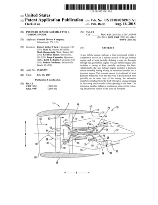
  • 1. THELETTERETUTTAA ANIMATIONUS 20180230913A1 (19)United States (12)Patent Application Publication (10)Pub.No.:US2018/0230913 A1 Clark et al. (43) Pub. Date: Aug. 16, 2018 (54) PRESSURE SENSOR ASSEMBLY FOR ATURBINE ENGINE (52) U.S. CI.CPC ............ F02C 9/24 (2013.01); F23N 2025/04 (2013.01); GOIL 9/008 (2013.01); GOIL 9/0076 (2013.01)(71) Applicant: General Electric Company, Schenectady,NY (US) (57) ABSTRACT(72) Inventors: RobertArthur Clark, Cincinnati,OH (US); Hejie Li,Mason,OH (US); Mark Rosenzweig, West Chester, OH (US); K ’Ehleyr James, Sharonville, OH (US); Jorge Camacho, Queretaro (MX);Keith F .Beatty ,Cincinnati, OH (US); Joshua Friedman, Jacksonville Beach, FL (US) (21) Appl.No.: 15/429,573 A gas turbine engine includes a liner positioned within a compressorsection or a turbine section of the gas turbine engine and at least partially defining a core air flowpath through the gas turbine engine. The gas turbine engine also includes a casing at least partially enclosing the liner. Additionally, the gas turbine engine includes a pressure sensorassembly having a body,an extension member,and a pressure sensor. The pressure sensor is positioned at least partially within the body and the body is positioned at least partially on an outer side of the casing, the extension member extending from thebody through a casing opening in the casing and towards a liner opening in the liner. The extension member defines a continuous sense cavity expos ing the pressure sensor to the core air flowpath . (22) Filed: Feb. 10,2017 (51) Publication Classification Int. Ci. F02C 9/24 (2006.01) GOIL 9/00 (2006.01) 7810 -54Xudover by 76 62 -- - - www : -- -- ho-- annannarnannananna -- 4449 3430 12R a tervvvvvvwvVAM wanananananana wergh baki ? ? ? ? ? 3027 74 322 --- - - - - -
  • 2. 46 62 persona78 10 54 Patent Application Publication wwwwww 58 62- A whatthaeuth when www - : E w -3636 -34 **** 12 * w .www too mongwwwwwwwwwwwwwwwwwwwwwwwwwwwww Wwwwwwwwwwwwwwwwwww - w www. w wwwwwwwwwwwwwwwwwwwwwwwwwwwwwwwwwww . wwww.** wwwwwwwwwww persones WWWWWWWWWWWWWW D Aug. 16 , 2018 Sheet 1 of 7 481 40 24 www . 26 18 Zzza 4 74 30 Throughthe sé FIG.1 US 2018/0230913 A1 ***********************
  • 3. wwwwwwwwwwwww US 2018/0230913 A1 901 X OXOCODO ?????????????????????, ????????????????????????????????20 *XXX**C KOUSKOOD 201 WWW DOL 051 / 1 97 www KMK* Aug. 16 , 2018 Sheet 2 of 7 La AKTIVITITIYHTLINYT ZE BIL ******* 798 91 WY COLOS 9 ????????????????????????N G MG /ZZZZZZZZZZZZZ952 ZIL DEKSELZ ZZZZZZZZI AR unded w Patent Application Publication MAALAAAAAAAAAAAAAAAAAAAAAAAAAAAA001 ago ISI
  • 4. Patent Application Publication Aug. 16 , 2018 Sheet 3 of 7 US 2018/0230913 A1 w 1 pocco / 1 w A w wwwwwwwwww www LALALA www 1401158 1144 1754 KIAw - 146175 172 1 zzzz goldings z zzzz POGODK Z SIIIIIIZ 150. ws FIG.3
  • 5. Patent Application Publication Aug. 16 , 2018 Sheet 4 of 7 US 2018/0230913 A1 138L134 WWWWWWWW W AAAAAAAAA.. . **** ** Madadadada **** 1500MAS zsl 150 ** * 9EL ***** ** * SL001 156 x * dadadada ZE 104 2da act 110 801 ZZZZZZZZZZZZZN151/ son .841 Sen ---150 ook book w AcabadookoowoMAMMALALACLAADALLALAAAAAAAAAAAAAAAAAAAAAAA w wwfr wwww poona DUKKERXXXXXXXXXXXXXXXXXXXXXXXXAAAAAAAAAAAAC 144 AAAAAAAAAAAAAAAAAAA . . . . . . . WAKA * * * * AXXARA*AXAR . AMA Add oond w Popco www ** * KERS 1 I
  • 6. Patent Application Publication Aug. 16 , 2018 Sheet 5 of 7 US 2018/0230913 A1 1 N 184 1 -****-uuuuuu-**-- 168 - ****YWwwwwwww - 1168 -160 - 16221 AY 156 140www158 ) 1445 and7 175 1721 7 2 1 ar 176-1767 S w ZZZZZZZ STIILIT150- Doodnot FIG.5
  • 7. Patent Application Publication Aug. 16 , 2018 Sheet 6 of 7 US 2018/0230913 A1 66ond 0 -184**** *** w * ********************** **** ** ******** ************************* 2 -168LLLLSHARELARISTALLAT -160 1 W 156*** 158 140 144oonoportetopo 1 ondisshanom 168 175 175 1725 7 12 7176 s 19.ZZZZZZZZZERIEMonks new b i 180 178 ZZZZZZZZZZZ LII 1504 SIIIII 108 1non Facest
  • 8. Patent Application Publication Aug. 16, 2018 Sheet 7 of 7 US 2018/0230913 A1 WA ... googad pocopobo 1521 15 cand152w www hann * MWWW. wwwwwwwwwwww 1bobo wwww Penghitung Boererateand
  • 9. US 2018/0230913 A1 Aug. 16, 2018 PRESSURE SENSOR ASSEMBLY FOR A TURBINE ENGINE FIELD [0001] Thepresentsubjectmatter relatesgenerally to a gas turbine engine, or more particularly to a pressure sensor assembly for a gas turbine engine. BACKGROUND [0002] Certain combustors on aircraft engines may be particularly susceptible to combustion dynamics. Under certain engine operating conditions, significant transient pressure waves ( pings”) can be present, particularly in an annular combustor. These pressure waves, if of sufficient magnitude, may cause high cycle fatigue of combustor components, long before the hardware would need to be replaced under normaloperations. [0003] One knownapproach to combustor dynamic issues can involve carefulmapping ofproblem regimes using test engines with multiple combustor instrumentation pressure sensors.Aircraft fuel schedulesdeveloped from this process and subsequently programmed into engine control were expected to avoid all problem areas.Despite thismapping, however, subtle differences between engines may still adversely affect combustion dynamics behavior. These changes may be due to parameters includingmanufacturing variations, engine deterioration, fuel composition, or unex pected flight conditions. [0004] Therefore, itmaybe beneficialtomonitorcombus tor dynamics during fielded operation of the gas turbine engine such that modifications to one or more control parameters may bemade to reduce the combustor dynamics in the eventthey progress above a certain threshold.How ever, it can be difficult to accurately measure combustor dynamics during operation given the relatively harsh con ditions within a combustion chamber of the gas turbine engine. [0005] Accordingly, features for monitoring combustion dynamics in aircraft engines are desired. Specifically, fea tures for more accurately measuring a pressure within a combustion section of a gas turbine engine would be par ticularly useful. casing, the extension member extending from the body through the casing opening in the casing and towards the liner opening in the liner, the extension member defining a continuoussense cavity exposing the pressure sensor to the core air flowpath . [0008] In certain exemplary embodiments the liner is an outer liner of a combustor assembly of the gas turbine engine, and wherein the casing is a combustor casing . 10009 ] Additionally, in other exemplary embodiments the pressure sensor includes a diaphragm exposed to the sense cavity of the extension member, the pressure sensor further includes piezo-electric material positioned against the dia phragm opposite the sense cavity. [0010] Moreover, in certain exemplary embodiments the pressure sensor includes a diaphragm exposed to the sense cavity of the extension member, and wherein the pressure sensor is an optical-based sensor for measuring a deflection of the diaphragm . For example, in certain exemplary embodiments the optical-based sensormay include an opti cal laser directed to the diaphragm . [0011] Further, in certain exemplary embodiments the extension memberdefinesone ormore coolingholes located inward of the casing along the radial direction and outward of the liner along the radial direction. [0012] Additionally, in certain exemplary embodiments the liner includes a ferrule, and the extension member extends into the ferrule. [0013] Moreover, in certain exemplary embodiments the pressure sensor assembly is removably coupled to the cas ing. [0014] Further, in certain exemplary embodiments the pressure sensor assembly further includes a clamp nut, wherein the clamp nut is removably coupled to the body to hold the sensor in position. [0015] Additionally, in certain exemplary embodiments the gas turbine engine further includes a plurality ofpressure sensor assemblies arranged along the circumferentialdirec tion of the gas turbine engine. [0016] Moreover, in certain exemplary embodiments the casing opening of the casing and the liner opening of the liner are each configured as part of a borescope inspection port. [0017]. Further, in certain exemplary embodiments the liner is a liner of a high pressure turbine in the turbine section of the gas turbine engine, and wherein the casing is a turbine casing. [0018] In another exemplary embodiment of the present disclosure, a pressure sensor assembly is provided for a gas turbine engine. The gas turbine engine defines a radial direction and includes a liner at leastpartially defining a core air flowpath through a compressor section or a turbine section and a casing at leastpartially enclosing the liner. The pressure sensor assembly includes a body configured for positioning adjacent to the casing of the gas turbine engine, and a pressure sensorpositioned at least partially within the body. The pressure sensor assembly further includes an extension member extending from thebody and configured to extend at least partially through a casing opening in the casing and towards a lineropening in the liner, the extension member defining a continuous sense cavity to expose the pressure sensor to the core air flowpath of the gas turbine engine. [0019] In certain exemplary aspects the pressure sensor includes a diaphragm exposed to the sense cavity of the BRIEF DESCRIPTION 10006 ] Aspects and advantages ofthe inventionwillbe set forth in part in the following description, ormay be obvious from the description,ormaybe learned through practice of the invention . [0007] In one exemplary embodimentofthe present dis closure a gas turbine engine defining a radial direction and a circumferential direction is provided. The gas turbine engine includes a liner positioned within a compressor section or a turbine section of the gas turbineengine and at least partially defining a core air flowpath through the gas turbine engine. The liner defines a liner opening. The gas turbine engine also includes a casing at least partially enclosing the liner, the casing defining first, inner side along the radial direction, a second, outer side opposite the first side, and a casing opening. The gas turbine engine also includes a pressure sensor assembly comprising a body,an extension member, and a pressure sensor, the pressure sensor position at least partially within the body and the body positioned at least partially on the second side of the
  • 10. US 2018/0230913 A1 Aug. 16, 2018 extension member, wherein the pressure sensor further includes piezo-electric materialpositioned against the dia phragm opposite the sense cavity. [0020] Additionally,in certain exemplaryaspects thepres sure sensorincludesa diaphragm exposed to thesense cavity ofthe extension member,wherein the pressure sensor is an optical-based sensor for measuring a deflection of the dia phragm . For example, in certain exemplary aspects the optical-based sensor includesan opticallaser directed to the diaphragm . [0021] Moreover, in certain exemplary aspects the exten sion member defines one or more cooling holes located inward of the casing along the radial direction and outward of the liner along the radial direction when the pressure sensor assembly is installed in the gas turbine engine. 0022]. Further, in certain exemplary aspects the pressure sensor assembly is configured to be removably coupled to the casing. 10023] Additionally, in certain exemplary aspects the pres sure sensorassembly further comprises a clampnut,wherein the clamp nutis removably coupled to thebody to hold the sensor in position. [0024] Moreover, in certain exemplary aspects the lineris an outer liner of a combustor assembly of the gas turbine engine,wherein the casing is a combustor casing. [0025] These and otherfeatures,aspectsand advantagesof the present invention will become better understood with reference to the following description and appended claims. Theaccompanying drawings, which are incorporated in and constitute a partofthis specification, illustrate embodiments ofthe invention and, togetherwith thedescription,serve to explain the principles of the invention. DETAILED DESCRIPTION [0034] Reference will now be made in detail to present embodiments of the invention, one or more examples of which are illustrated in the accompanying drawings. The detaileddescription usesnumerical and letter designationsto referto features in the drawings.Likeorsimilar designations in thedrawings and description have been used to refer to like or similar parts of the invention . As used herein , the terms “ first" , "second”, and “ third” may be used inter changeably to distinguish one component from another and are not intended to signify location or importance of the individualcomponents. The terms“ forward” and “aft” refer to relative axial positionswithin a gasturbineengine,with forward referring to a position closer to an engine inlet and aft referring to a position closer to an engine nozzle or exhaust. The terms" upstream " and " downstream ” refer to the relative direction with respect to fluid flow in a fluid pathway. For example , " upstream ” refers to the direction from which the fluid flows, and “downstream ” refers to the direction to which the fluid flows. [0035] Referring now to the drawings, wherein identical numerals indicate the same elements throughoutthe figures, FIG . 1 is a schematic cross-sectional view of a gas turbine engine in accordancewith an exemplary embodimentof the present disclosure.Moreparticularly,forthe embodimentof FIG . 1, the gas turbine engine is a high-bypass turbofan jet engine 10, referred to herein as "turbofan engine 10.” As shown in FIG . 1, the turbofan engine 10 defines an axial direction A (extending parallel to a longitudinal centerline 12 provided for reference), a radial direction R , and a circumferential direction (i.e., a direction extending about the axial direction A ; not depicted).In general,the turbofan 10 includes a fan section 14 and a core turbine engine 16 positioned downstream from the fan section 14 . [0036] The exemplary core turbine engine 16 depicted generally includes a substantially tubular outer casing 18 that definesan annular inlet 20. The outer casing 18 encases, in serial flow relationship,a compressor section including a booster or low pressure (LP) compressor 22 and a high pressure (HP) compressor 24; a combustion section 26 ; a turbine section including a high pressure (HP) turbine 28 and a low pressure (LP) turbine 30, and a jet exhaustnozzle section 32. A high pressure (HP) shaft or spool34 drivingly connects theHP turbine 28 to the HP compressor 24. A low pressure (LP) shaft or spool 36 drivingly connects the LP turbine 30 to theLP compressor 22. The compressor section, combustion section 26 , turbine section , and jet exhaust nozzle section 32 together define a core air flowpath 37 through thecore turbine engine 16. [0037] For the embodiment depicted, the fan section 14 includes a variable pitch fan 38 having a plurality offan blades 40 coupled to a disk 42 in a spaced apartmanner.As depicted, the fan blades 40 extend outwardly from disk 42 generally along theradialdirection R . Each fan blade 40 is rotatablerelativeto the disk 42 abouta pitch axis P by virtue ofthe fan blades 40 being operatively coupled to a suitable actuation member 44 configured to collectively vary the pitch of the fan blades 40 in unison. The fan blades 40, disk 42, and actuationmember 44 are together rotatable aboutthe longitudinal axis 12 by LP shaft 36 across a power gearbox 46 . The power gear box 46 includes a plurality of gears for stepping down the rotational speed of the LP shaft 36 to a more efficient rotational fan speed . BRIEF DESCRIPTION OF THE DRAWINGS [0026 ] A full and enabling disclosureofthepresentinven tion, including the best mode thereof, directed to one of ordinary skill in the art, is set forth in the specification, which makes reference to the appended figures, in which: [0027] FIG . 1 is a schematic cross-sectionalview of an exemplary gasturbine engine according to various embodi ments ofthe present subjectmatter. [0028] FIG . 2 is a schematic, cross-sectional view of a combustor assembly and turbine in accordance with an exemplary embodiment of the present disclosure. [0029] FIG . 3 is a close up, cross-sectional view of a pressure sensor assembly in accordance with an exemplary embodiment of the present disclosure. [0030] FIG . 4 is a schematic, cross-sectional view of a combustor assembly and turbine in accordance with another exemplary embodimentofthe present disclosure. [0031) FIG . 5 is a close up, cross-sectional view of a pressure sensorassembly in accordancewith another exem plary embodiment ofthe present disclosure. [0032] FIG . 6 is a close up, cross-sectional view of a pressure sensor assembly in accordance with yet another exemplary embodiment of the present disclosure. [0033] FIG . 7 is a schematic,axial view of a combustion section of the gas turbine engine including a plurality of pressure sensorassemblies in accordancewith an exemplary embodiment of the present disclosure.
  • 11. US 2018/0230913 A1 Aug. 16, 2018 [0038] Referring still to the exemplary embodiment of FIG . 1, the disk 42 is covered by rotatable front nacelle 48 aerodynamically contoured to promote an airflow through the plurality of fan blades 40. Additionally, the exemplary fan section 14 includesan annular fan casing orouter nacelle 50 that circumferentially surroundsthe fan 38 and/oratleast a portion of the core turbine engine 16 . The nacelle 50 is supported relative to the core turbine engine 16 by a plurality of circumferentially-spaced outlet guide vanes 52. More over,a downstream section 54ofthenacelle 50 extends over an outerportion of the core turbine engine 16 so as to define a bypass airflow passage 56 therebetween. [0039] During operation of the turbofan engine 10, a volume of air 58 enters the turbofan 10 through an associ ated inlet 60 ofthe nacelle 50 and/or fan section 14. As the volume of air 58 passes across the fan blades 40, a first portion ofthe air 58 asindicated by arrows62 is directed or routed into the bypass airflow passage 56 and a second portion of the air 58 as indicated by arrow 64 is directed or routed into theLP compressor 22. The ratio between the first portion of air 62 and the second portion of air 64 is commonly known as a bypass ratio. The pressure of the second portion of air 64 is then increased as it is routed through the high pressure (HP) compressor 24 and into the combustion section 26, where it is mixed with fuel and burned to provide combustion gases 66. [0040] The combustion gases 66 are routed from the combustion section 26 , through the HP turbine 28 where a portion of thermal and/orkinetic energy from the combus tion gases 66 is extracted via sequential stages ofHP turbine stator vanes 68 that are coupled to the outer casing 18 and HP turbine rotor blades 70 that are coupled to the HP shaft or spool34, thus causing the HP shaft or spool34 to rotate, thereby supporting operation of the HP compressor 24. The combustion gases66 are then routed through the LP turbine 30 where a second portion of thermal and kinetic energy is extracted from thecombustion gases66 via sequentialstages of LP turbine stator vanes 72 that are coupled to the outer casing 18 and LP turbine rotorblades 74 that are coupled to the LP shaft or spool 36 , thus causing the LP shaft or spool 36 to rotate, thereby supporting operation of the LP com pressor 22 and/or rotation of the fan 38. [0041] The combustion gases 66 are subsequently routed through the jet exhaustnozzle section 32 ofthe core turbine engine 16 to provide propulsive thrust. Simultaneously, a pressure of the first portion of air 62 is substantially increased as the first portion of air62 is routed through the bypass airflow passage 56 before it is exhausted from a fan nozzle exhaust section 76 ofthe turbofan 10, also providing propulsive thrust. The HP turbine 28, theLP turbine 30,and thejetexhaustnozzle section 32atleast partially define a hot gaspath 78 for routing the combustion gases 66 through the core turbine engine 16. [0042] It should be appreciated ,however, that the exem plary turbofan engine 10 depicted in FIG . 1 is by way of example only, and that in other exemplary embodiments, the turbofan engine 10 may have any other suitable configura tion. Additionally, or alternatively, aspects of the present disclosure may be utilizedwith any other suitable aeronau tical gas turbine engine,such as a turboshaft engine, turbo prop engine, turbojet engine, etc .Moreover, aspects of the present disclosure may further be utilized with any other land-based gas turbine engine, such as a power generation gasturbineengine,orany aeroderivative gasturbine engine, such as a nautical gas turbine engine. [0043] Referring now to FIG . 2, a close-up, side, cross sectionalview is provided ofa combustor assembly 100 and turbine in accordance with an exemplary embodimentofthe presentdisclosure. In at least certain exemplary aspects,the combustorassembly 100 of FIG . 2 may bepositioned in the combustion section 26 of the exemplary turbofan engine 10 of FIG . 1, and similarly, the turbine of FIG . 2 may be positioned in the turbine section ofthe exemplary turbofan engine 10 of FIG . 1. [0044] As shown, the combustor assembly 100 generally includes an inner liner 102 extending between an aftend 104 and a forward end 106 generally along the axial direction A , aswell as an outerliner 108 also extending between an aft end 110 and a forward end 112 generally along the axial direction A . The inner and outer liners 102, 108 together at least partially define a combustion chamber 114 therebe tween. The inner and outer liners 102, 108 are each attached to or formed integrally with an annular dome. More par ticularly, the annular dome includes an inner dome section 116 formed integrally with the forward end 106 of the inner liner 102 and an outer domesection 118 formed generally with the forward end 112 of the outer liner 108. Further, the inner and outer dome section 116, 118 may each be formed integrally (or alternatively may be formed of a plurality of components attached in any suitablemanner) andmay each extend along the circumferential direction C (see FIG . 6) to define an annular shape. 10045 ] For the embodiment depicted, the inner liner 102 and the outer liner 108 are each formed ofa ceramic matrix composite (CMC)material,which is a non-metallic material having high temperature capability. Exemplary CMC mate rials utilized for such liners 102, 108 may include silicon carbide, silicon, silica or alumina matrix materials and combinations thereof.However, in other exemplary embodi ments, oneorboth of the inner liner 102 and outer liner 108 may instead be formed of any other suitable material, such as a suitable metal material. [0046] Additionally, it should be appreciated that in other embodiments, the combustor assembly 100 may not include the inner and/or outer dome sections 116 , 118;may include separately formed innerand/orouterdomesections 116, 118 attached to therespective inner liner 102 and outer liner 108; ormay have any other suitable configuration. [0047] Referring still to FIG . 2, the combustor assembly 100 further includes a plurality offuelair mixers 124 spaced along the circumferential direction C (see FIG ., 6 , below ) and positioned at least partially within the annular dome. More particularly, the plurality of fuel air mixers 124 are disposed at least partially between the outer dome section 118 and the inner domesection 116 along the radialdirection R . Compressed air from the compressor section of the turbofan engine 10 flowsinto or through the fuel air mixers 124,where the compressed airismixed with fuel and ignited to create the combustion gases 66 within the combustion chamber 114. The inner and outer dome sections 116, 118 are configured to assist in providing such a flow of com pressed air from the compressor section into or through the fuel air mixers 124 . For example, theouter domesection 118 includes an outer cowl 126 at a forward end and the inner dome section 116 similarly includes an inner cowl 130 at a forward end. The outer cowl 126 and inner cowl 130 may assist in directing the flow of compressed air from the
  • 12. US 2018/0230913 A1 Aug. 16, 2018 compressor section 26 into or through one ormore of the fuel airmixers 124. Again,however, in other embodiments, the annular domemay be configured in any other suitable manner. [0048] Additionally,as is discussed above, thecombustion gases 66 flow from the combustion chamber 114 into and through the turbine section of the turbofan engine 10, where a portion of thermal and/or kinetic energy from the com bustion gases 66 is extracted via sequential stages of turbine stator vanes and turbine rotor blades. Notably, the turbine depicted in FIG . 2 is configured as an HP turbine 28, located immediately downstream of the combustion chamber 114 defined by the combustor assembly 100 of the combustion section 26. [0049] As is depicted , the exemplary HP turbine 28 of FIG . 2 includes a first stage of turbine nozzles 132 posi tioned at a forward end of the HP turbine 28, at a location downstream of, or rather immediately downstream of, the combustion chamber 114 of the combustor assembly 100. Additionally, the first stage of turbine nozzles 132 is posi tioned immediately upstream ofa first stageof turbine rotor blades 134. Aswill be described in greater detailbelow , the first stage ofturbine nozzles 132 is configured to orient the combustion gases 66 from the combustion chamber 114 in a desired flow direction to increase a performance of the HP turbine 28. For the embodiment depicted, the first stage of turbinenozzles 132 includes a plurality of individual turbine nozzles spaced along the circumferential direction C (see FIG .6) and extending generally along the radialdirection R from an inner turbine liner 136 to an outer turbine liner 138. The inner and outer turbine liners 136 , 138 at least partially define a portion of the core air flowpath 37 extending through the HP turbine 28 of the turbine section. The outer turbine liner 138 is, for the embodimentdepicted, coupled to the outer liner 108 of the combustor assembly 100 at a forward end and extendsaftwardly /downstream pastthe first stage of turbine rotor blades 134. [0050] Asis also depicted in FIG .2,thegas turbine engine further includes a casing atleastpartially enclosing the outer liner 108 of the combustor assembly 100 and the outer turbine liner 138of theHPturbine28.More specifically,the gas turbine engine further includes a combustor casing 140 at least partially enclosing the outer liner 108 of the com bustor assembly 100, as well as a turbine casing 142 at least partially enclosing the outer turbine liner 138 of the HP turbine 28. Each of the combustor casing 140 and turbine casing 142 defines a first side 144 proximate to and facing the respective liners 108, 138 (i.e., a radially inner side), a second side 146 opposite the first side 144 (i.e., a radially outer side), and a casing opening 148. Additionally, for the embodiment depicted, the outer liner 108 of the combustor assembly 100 and the outer turbine liner 138 of the HP turbine 28 also similarly include a liner opening 150. The liner openings 150 of the liners 108, 138 are substantially aligned with the casing openings 148 of the combustor casing 140 and turbine casing 142, respectively. It should be appreciated, that for the embodiment depicted, the casing openings 148 of the combustor casing 140 and turbine casing 142, as well as the liner openings 150 of the outer liner 108 and outer turbine liner 138 are configured aspart of respective borescope openings, also referred to as bore scope inspection ports. For example, the gas turbine engine depicted includes a borescope plug 151 positioned in the casingopening 148 ofthe turbinecasing 142 and in the liner opening 150 ofthe outer turbine liner 138. [0051] As willbeappreciated, itmaybebeneficialduring operation of the gas turbine engine to monitor a dynamic pressure within the core air flowpath 37 of the gas turbine engine.More specifically, itmaybe beneficialduring opera tion ofthe gas turbine engine to monitor a dynamic pressure within the combustion chamber 114 of the combustor assem bly 100 and/orwithin the core air flowpath 37 at a forward end of the HP turbine 28.Monitoring the dynamic pressure within these sections of the gas turbine enginemay allow for the gas turbine engine to monitor any combustor dynamics therein ,and if necessary,modify operation ofthe gas turbine engine to minimize such combustor dynamics. [0052] Accordingly, for the embodimentdepicted,the gas turbine engine further includes a pressure sensor assembly 152 configured tomonitor a pressure within the combustion chamber 114 of the combustor assembly 100 or within the core air flowpath 37 in the HP turbine 28 ( e.g ., at a forward end of theHPturbine 28).More specifically, fortheembodi ment depicted in FIG . 2, the pressure sensor assembly 152 is configured to monitor a dynamic pressure within the combustion chamber 114 of the combustor assembly 100 . [0053] Referringnow also to FIG . 3,providinga close-up, cross-sectional view of the exemplary pressure sensor assembly 152ofFIG . 2, the pressure sensor assembly 152 generally includes a body 154 and an extension member 156. The body 154 is positioned at least partially on the second side 146 ofthe combustorcasing 140.More specifi cally, for the embodiment depicted, the body 154 is posi tioned completely on the second side 146 of the combustor casing 140 (i.e., does notextend into or through the casing opening 148). By contrast, the extension member 156 extends from the body 154 at least partially through the casing opening 148 in the combustor casing 140 and towards the liner opening 150 and the outer liner 108 of the com bustor assembly 100. [0054] Additionally, for the embodiment depicted, the pressure sensor assembly 152 is removably coupled to the combustor casing 140. More specifically, the extension member 156 of the pressure sensor assembly 152 defines a threaded outer surface 158. The threaded outer surface 158 of the pressure sensor assembly 152 is configured to engage a threaded section 160 of the casing opening 148 in the combustor casing 140. Moreover, for the embodiment depicted, the pressure sensor assembly 152 includes a sec ondary retention and anti-rotationmember 162to ensure the pressure sensor assembly 152 does not come unscrewed/ unattached during engine operation . For the embodiment depicted, the member 162 is configured as a tab-washer. However, in other embodiments, any other suitable member may be provided. Notably, however, in other exemplary embodiments, an outer surface of thebody 154may instead define a threaded section configured to removably attach the pressure sensor assembly 152 to a correspondingly threaded section of the casing (e.g., casing 140). Additionally, or alternatively, the pressure sensor assembly 152 may be removably coupled to the casing (e.g., casing 140) in any other suitable manner, or alternatively still,may be perma nently coupled to the casing (e.g., casing 140). [0055] Additionally, for the embodiment depicted, the extensionmember 156 ismoveably engaged with the outer liner 108 ofthe combustorassembly 100.More specifically, the outer liner 108 ofthe combustor assembly 100 includes
  • 13. US 2018/0230913 A1 Aug. 16, 2018 a ferrule 176 and the extensionmember 156 extends into the ferrule 176 . The ferrule 176 includes a first radially outer member 178 and a second radially innermember 180. The extension member 156 is slidably received through the radially outermember 178 such that the extensionmember 156 maymove generally along the radialdirection R relative to the radially outer member 178. Additionally, for the embodiment depicted, the radially outer member 178 is slidably connected to the radially innermember 180,allow ing the radially outer member 178 to move generally along the axial direction A and in the circumferential direction C relative to the radially inner member 178. Such a configu ration effectively gives the extension member 156 six degrees of freedom relative to the outer liner 108 of the combustor assembly 100. [0056] Asmay also be seen in FIG . 3, the pressure sensor assembly 152 further includes a pressure sensor 164. The pressure sensor 164 is positioned at leastpartially within the body 154 and, for the embodiment depicted, removably attached thereto. More specifically, the pressure sensor assembly 152 includes a clamp nut 166 ,the clamp nut 166 rotatably engaged with the body 154 through a threaded connection 165 to removably couple thepressure sensor 164 at least partially within the body 154.Again, however, the clampnut 166 may additionally,or alternatively,be remov ably coupled to thebody 154 in any other suitablemanner. [0057] Additionally, for the embodiment depicted the pressure sensor 164 is configured as a piezoelectric sensor. More specifically,for the embodimentdepicted,thepressure sensor 164 includes a diaphragm 168 and a piezoelectric material 170 positioned against the diaphragm 168. Further, as is shown, the extension member 156 defines a continuous sense cavity 172 for exposing the pressure sensor 164 to the core air flowpath 37, or more specifically, for the embodi mentdepicted, for exposing the pressure sensor 164 to the combustion chamber 114 of the combustor assembly 100. Additionally, theextensionmember 156 defines oneormore cooling holes 175 to reduce a temperature of the air within the sense cavity 172 of the extension member 156. The cooling holes 175 are positioned inward ofthe combustor casing 140 along the radial direction R and outward ofthe outerliner 108 along the radialdirection R. Accordingly, the coolingholes 175 are exposed to a compressor discharge air flowing between the combustor casing 140 and outer liner 108. A pressure of the compressor discharge air may gen erally be higher than a pressure ofthe air/combustion gases within the combustion chamber 114. Additionally, a tem perature of the compressor discharge air may generally be lower than a temperatureofthe air/combustion gaseswithin the combustion chamber 114. Accordingly,with the con figuration depicted in FIG . 3, the sense cavity 172 may fill with compressordischarge air,maintaining a temperature of the pressure sensor 164 at a lower temperature relative to a temperaturewithin the combustion chamber 114,andbelow a maximum operating temperature threshold . [0058] Referring still to the embodimentdepicted in FIG . 3 , the diaphragm 168 is positioned adjacent to and exposed to thesense cavity 172 of the extension member 156 and the piezoelectric material 170 is positioned against the dia phragm 168 opposite the sense cavity 172 ofthe extension member 156. The exemplary diaphragm 168 depicted is configured as a single layer ofmaterial, however,in other embodiments, the diaphragm 168 may instead be formed of a plurality oflayers ofmaterials.Accordingly,duringopera tion of the gas turbine engine, the pressure fluctuations within the combustion chamber 114 are translated through the compressor exit air within the sense cavity 172 of the extension member 156 to the diaphragm 168 of the pressure sensor 164, and further to the piezoelectric material 170. [0059] More specifically, during operation ofthe gas tur bine engine, pressure fluctuations within the combustion chamber 114 may compress air positioned within the sense cavity 172 of the extension member 156, translating such pressure fluctuations to the diaphragm 168 of the pressure sensor 164. The pressure fluctuations translated to the dia phragm 168 cause the diaphragm 168 to deform . The deformation of the diaphragm 168, in turn , causes the piezoelectric material170 to deform , andthe deformation of the piezoelectric material 170 generates an electrical signal. The electrical signal is provided through an electrical con nection line 174 of the pressure sensor 164 to, e.g., a controller (not shown) which may correlate the electrical signal to a pressure within the combustion chamber 114 of the gas turbine engine. As will be appreciated, such a pressure sensor 164 may be capable of differentiating between different frequencies and amplitudes of pressure changes/dynamics to which the diaphragm 168 is exposed, allowing the pressure sensor 164 to sense a specific fre quency and amplitude of combustor dynamics within the combustion chamber 114 of the gas turbine engine, if desired. 10060] Moreover, including a pressure sensor within a pressure sensor assembly in accordance with one more embodiments ofthe present disclosuremay allow forthe use of piezoelectric material to measure a pressure within the combustion chamber 114 of the gas turbine engine despite the elevated temperatures within the combustion chamber 114 the gas turbine engine thatwould otherwise preventuse of piezoelectric material. [0061] It should beappreciated,however, that the exem plary pressure sensorassembly 152 depicted in FIGS. 2 and 3 is provided by way of example only. In other exemplary embodiments, the pressure sensor assembly 152 may have any other suitable configuration, and further may be posi tioned at any other suitable location within the gas turbine engine. [0062] For example, reference will now bemade to FIG . 4,providing a gas turbine engine including a pressure sensor assembly 152 in accordance with another exemplary embodiment of the present disclosure. It should be appre ciated that the exemplary embodiment of FIG . 4 may be configured in substantially the samemanner as the exem plary embodiment described above with reference to FIGS. 2 and 3.Accordingly, the sameor similarnumbersmay refer to the same or similar part. [0063] As is depicted, for the exemplary embodiment of FIG . 4 , the gas turbine engine includes a pressure sensor assembly 152, thepressure sensor assembly 152 including a body 154, an extension member 156 , and a pressure sensor 164. The pressure sensor 164 is positioned at least partially within thebody 154,and the body 154 is positioned atleast partially on a second, a radially outer side 146 of a casing. Additionally, the extension member 156 extends from the body 154 through a casing opening 148 in the casing and towards a liner opening 150 in a liner. The extension member 156 defines a continuous sense cavity 172 exposing the pressure sensor 164 to a core air flowpath 37.
  • 14. US 2018/0230913 A1 Aug. 16, 2018 [0064] However, forthe embodiment depicted,the casing is instead configured as a turbinecasing 142 and the liner is instead configured as an outer turbine liner 138. Notably, the casing opening 148 in the turbine casing 142 and the liner opening 150 in the outer turbine liner 138 are each posi tioned proximate a first stage of turbine nozzles 132 (i.e ., radiallyoutward ofthe first stage ofturbinenozzles 132,and aligned with the first stage of turbine nozzles 132 along the axial direction A ).Additionally, forthe exemplary embodi ment depicted the pressure sensor assembly 152 has replaced a borescopeplug 151,and aborescopeplug 151has been positioned in thecasing and liner openings 148, 150 of the combustor casing 140 and outer liner 108, respectively (compare with FIG .2). [0065] Accordingly, the pressure sensor 164 of the pres sure sensor assembly 152 ofFIG . 4 may still be configured to detect combustor dynamics within the combustion cham ber 114. It should be appreciated, however, in other exem plary embodiments the pressure sensor assembly 152 may instead be positioned at any other suitable location within the turbine section,such as at any location forward of the first stage of turbine rotorblades 134 of the HP turbine 28, or aft of the first stage ofturbine rotorblades 134 of the HP turbine 28. [0066] Additionally, referring now to FIG . 5, a side, cross-sectional view ofyet another exemplary embodiment of a pressure sensor assembly 152is provided.Aswith the exemplary pressure sensor assembly 152 described above with reference to FIGS. 2 and 3, the exemplary pressure sensor assembly 152 of FIG . 5 includes a body 154, an extension member 156, and a pressure sensor 164. The pressure sensor 164 ispositioned atleastpartially within the body 154 and generally includes a diaphragm 168 positioned adjacent to and exposed to the sense cavity 172 of the extension member 156 . [0067] However, forthe exemplary embodimentdepicted , the pressure sensor 164 is an optical-based sensor configured to measure a deflection of the diaphragm 168 to , in turn , measure pressure within the combustion chamber 114.More specifically, for the embodiment depicted, the diaphragm 168 defines an enclosed, interior cavity 182. Additionally, the optical-based sensor includes an optical laser 184 directed at the diaphragm 168, or rather, directed at the interior cavity 182 of thediaphragm 168. The optical-based sensor is configured to measure light from the opticallaser 184 reflected from the internal cavity 182 of the diaphragm 168.Deformation of the diaphragm 168, and deformation of the internal cavity 182 of the diaphragm 168, changes characteristics of the light from the optical laser 184 reflected from the internal cavity 182 the diaphragm 168. Accordingly, the optical-based sensor may determine an amount of deflection/deformation of the diaphragm 168 based on the sensed characteristics of the light from the optical laser 184 reflected from the cavity 182, therefore determining a pressure within the core air flowpath 37. 0068] Moreover, it should be appreciated that in other exemplary embodiments, the pressure sensor assembly 152 including an optical-based sensormaybe configured in any other suitable manner. For example, referring to FIG . 6 , a side, cross-sectional view ofyet another exemplary embodi ment of a pressure sensor assembly 152 is provided. The pressure sensor assembly 152 ofFIG . 6 may be configured in substantially the same manner as the pressure sensor assembly 152 of FIG . 5. However, for the embodimentof FIG .6,a diaphragm 168ofthepressuresensorassembly 152 is positioned in a sense cavity 172 ofthe extensionmember 156 , such thatan edge of the diaphragm 168 is substantially flush with an inner surface 146 ofthe casing 140.Notably, in still other embodiments, the diaphragm 168 may further be positioned even closer to the combustion chamber 114 . For example in still other exemplary embodiments the diaphragm 168 may be positioned radially inward of the casing 140, e.g., such thatan edge of the diaphragm 168 is substantially flush with a radially outer surface ofthe outer liner 108. [0069] Furthermore, although for the embodiments described above the gas turbine engine is depicted including a single pressure sensor assembly 152, it should be appre ciated thatin other exemplary embodiments, the gas turbine enginemay additionally include a plurality pressure sensor assemblies 152. For example,referringnow briefly to FIG . 7, a schematic, axial view of a combustion section 26 of a gas turbine engine in accordance with another exemplary embodiment of the present disclosure is provided. The combustion section 26 may be configured in substantially the samemanner as the exemplary combustion section 26 described above with reference to FIG . 2 . For example, the combustion section 26 generally includes an outer combus tor casing 140 enclosing a combustor assembly 100, the combustorassembly 100 including an outerliner 108 at least partially defining a combustion chamber 114. For the exem plary embodiment ofFIG . 7 , the gas turbine engine includes a plurality ofpressure sensor assemblies 152 arranged along the circumferential direction C of the gas turbine engine. More specifically, for the embodiment depicted, the gas turbine engine includes four pressure assemblies 152 arranged substantially evenly along the circumferential direction C of the gas turbine engine. Such a configuration may allow for the gas turbine engine to measure combustor dynamics within the combustion chamber 114 thatmay vary along the circumferential direction C . [0070] It should be appreciated , however, that in other exemplary embodiments,the gas turbine enginemay include any other suitable numberofpressure sensorassemblies 152 arranged in other suitablemanner.Additionally, each ofthe plurality pressure sensor assemblies 152 depicted in FIG . 7 may be configured in substantially the samemanner as one or more of the exemplary pressure sensor assemblies 152 described above with reference to FIGS. 2 through 6 . Accordingly, in certain exemplary embodiments,the plural ity of pressure sensor assemblies 152 may instead be posi tioned within the turbine section of the gas turbine engine. [0071] Inclusion ofone or more pressure sensor assem blies in accordance with an exemplary embodiment ofthe present disclosure with a gas turbine enginemay allow for the gas turbine enginetomore accurately monitorcombustor dynamicswithin e.g., a combustion chamber of a combus tion section ofthe gas turbine engine, or at a forward end of the turbine section of the gas turbine engine.More specifi cally, inclusion ofone ormore pressure sensor assemblies in accordance with an exemplary embodiment of the present disclosure may allow for use of more accurate pressure sensors which may otherwise be incapable ofwithstanding the relatively elevated temperatures within the combustion chamber of the gas turbine engine. [0072] This written description uses examplesto disclose the invention, including the best mode, and also to enable any person skilled in the art to practice the invention,
  • 15. US 2018/0230913 A1 Aug. 16, 2018 7 including making and using any devices or systems and performing any incorporated methods. Thepatentable scope of the invention is defined by the claims, and may include other examples that occur to those skilled in the art. Such other examples are intended to be within the scope of the claims if they include structural elements that do not differ from the literal language of the claims, or if they include equivalent structural elements with insubstantial differences from the literal languages of the claims. What is claimed is: 1. A gas turbine engine defining a radial direction and a circumferentialdirection,the gas turbine enginecomprising: a liner positioned within a compressor section or a turbine section ofthe gas turbine engine and at least partially defining a core air flowpath through the gas turbine engine, the liner defining a liner opening; a casing at least partially enclosing the liner, the casing defining a first, inner side along the radial direction , a second,outer side opposite the firstside,and a casing opening; and a pressure sensor assembly comprising a body,an exten sion member, and a pressure sensor, thepressure sensor positioned at least partially within the body and the body positioned at least partially on the second side of the casing, the extension member extending from the body through the casing opening in the casing and towards the liner opening in the liner, the extension member defining a continuous sense cavity exposing the pressure sensor to thecore air flowpath . 2. The gasturbine engine ofclaim 1,wherein the liner is an outer liner of a combustor assembly of the gas turbine engine, and wherein the casing is a combustor casing. 3. The gas turbine engine of claim 1, wherein the pressure sensor comprises a diaphragm exposed to thesense cavity of the extension member, and wherein the pressure sensor further comprises piezo-electric materialpositioned against thediaphragm opposite the sense cavity. 4. The gas turbine engine ofclaim 1, wherein the pressure sensorcomprises a diaphragm exposed to the sense cavity of the extension member,and wherein thepressure sensor is an optical-based sensor for measuring a deflection of the dia phragm . 5. The gas turbine engineofclaim 4,wherein theoptical based sensor includes an optical laser directed to the dia phragm . 6. The gas turbine engine of claim 1,wherein the exten sion member defines one or more cooling holes located inward of the casing along the radial direction and outward of the liner along the radial direction. 7. The gas turbine engine of claim 1, wherein the liner comprises a ferrule , and wherein the extension member extends into the ferrule. 8. Thegas turbine engine ofclaim 1,wherein the pressure sensor assembly is removably coupled to the casing. 9. Thegasturbine engineof claim 1,wherein thepressure sensor assembly further comprises a clampnut,and wherein the clampnut is removably coupled to thebody to hold the sensor in position. 10. The gas turbine engineofclaim 1,further comprising: a plurality ofpressure sensorassemblies arranged along thecircumferentialdirection ofthe gas turbineengine. 11. The gas turbine engine of claim 1,wherein the casing opening of the casing and the lineropeningofthe liner are each configured as part of a borescope inspection port. 12. The gas turbine engine of claim 1, wherein the liner is a liner of a high pressure turbine in the turbine section of the gas turbine engine, and wherein the casing is a turbine casing. 13. A pressure sensor assembly for a gas turbine engine defining a radial direction and comprising a liner at least partially defining a core air flowpath through a compressor section or a turbine section and a casing at least partially enclosing the liner, the pressure sensor assembly compris ing: a bodyconfigured for positioningadjacentto thecasingof the gas turbine engine; a pressure sensor positioned at least partially within the body; and an extension member extending from thebody and con figured to extend at least partially through a casing opening in the casing and towards a liner opening in the liner, the extension member defining a continuous sense cavity to expose the pressure sensor to the core air flowpath of the gas turbine engine. 14.Thepressure sensorassembly ofclaim 13, wherein the pressure sensor comprises a diaphragm exposed to thesense cavity of the extension member, and wherein the pressure sensor further comprises piezo-electric materialpositioned against the diaphragm opposite the sense cavity. 15. Thepressure sensorassembly ofclaim 13,wherein the pressure sensor comprises a diaphragm exposed to the sense cavity of the extension member, and wherein the pressure sensor is an optical-based sensor formeasuring a deflection of the diaphragm . 16 . The pressure sensorassembly ofclaim 15,wherein the optical-based sensor includes an optical laser directed to the diaphragm . 17.Thepressure sensorassembly ofclaim 13,wherein the extensionmember definesone ormore cooling holes located inward of the casing along theradialdirection and outward of the liner along the radial direction when the pressure sensor assembly is installed in the gas turbine engine. 18. Thepressure sensorassembly ofclaim 13,wherein the pressure sensor assembly is configured to be removably coupled to the casing. 19.The pressure sensor assembly ofclaim 13,wherein the pressure sensorassembly further comprises a clamp nut,and wherein the clamp nut is removably coupled to the body to hold the sensor in position. 20. The pressure sensorassembly ofclaim 13,wherein the liner is an outer liner of a combustor assembly of the gas turbine engine, and wherein the casing is a combustor casing. * * * * *