SlideShare a Scribd company logo
1 of 13
Download to read offline
(12) United States Patent
Rosenzweig et al.
USOO86O7484B2
(10) Patent No.: US 8,607,484 B2
(45) Date of Patent: Dec. 17, 2013
(54) SYSTEM,COMPONENTSANDMETHOD FOR 3:56 A : R s Sight, Jr......................... S5- ww. alS .......
TREATING AEABRIC 4,894.935 A * 1/1990 Kretz .............................. 38,137
6,153,862 A * 1 1/2000 Job ............................... 219,521
(75) Inventors: Mark Rosenzweig, Chestnut Hill, MA 6,514,924 B1* 2/2003 Van Hauwermeiren
(US); Dan Bilger, Amherst, NH (US); et al. ....... ... 510,284
Dann Provolo, Barrington, RI (US); 6,910,291 B2 * 6/2005 Schwass ........................... 38/14
s s . . 6,922,911 B2 8/2005 Lam ................................ 34,239
Peggy Lam, Randolph, MA (US); Eric 2003, OO19087 A1 1/2003 Pasin et all
Wall, Auburn, AL (US) 2007/0295769 A1 12/2007 Burroughs
2008, 0217364 A1 9/2008 Fong
(73) Assignee: Euro-Pro Operating LLC, Newton, 2009/0173758 A1 T/2009 Hahn
MA (US) OTHER PUBLICATIONS
(*) Notice: Subject to any disclaimer, the term ofthis NoAuthorListed MountingYourJiffy(R)SteamerSteamboard.Jiffy
patent is extended or adjusted under 35 Steamer Company, LLC. Printed Jul. 23, 2010. Available at http://
U.S.C. 154(b) by 415 days. www.jiffysteamer.com/manager/file.asp?tableName=tblProducts
&idField-productID&namePrefix=pdf&idValue=412. Last
(21) Appl. No.: 12/860,554 accessed Feb. 8, 2011. 1 page.
No Author Listed Accessories for JiffyR. Steamers. Item #0892A
(22) Filed: Aug. 20, 2010 for Steamboard. Jiffy(R) Steamer Steamboard. Printed Jul. 23, 2010.
Available at http://www.jiffysteamer.com/accessories/viewdetails.
(65) Prior Publication Data asp?productId=412. Last accessed Feb. 8, 2011. 2 pages.
US 2011FOO3O249 A1 Feb. 10, 2011 * cited by examiner
(51) Int. Cl. Primary Examiner— Ismael Izaguirre
D6F 83/00 (2006.01) (74) Attorney, Agent, or Firm — Wolf, Greenfield & Sacks,
DO6C (5/OO (2006.01) P.C.
(52) U.S. Cl.
USPC .................................. 38/141; 38/144; 223/61 (57) ABSTRACT
(58) Field ofClassification Search A pad system for facilitating treatment ofa fabric includes a
USPC .. . . .. 38/103-141; 223/6870, 52-66 pad which is placed adjacent to a Support Surface, and fabric
Seeapplication file forcomplete search history. grips which securethefabricagainstthe pad.The fabricgrips
maybeattachableto thepad. The fabric grips may beusedto(56) References Cited
U.S. PATENT DOCUMENTS
2.437,084 A
3,217,434 A
* 3, 1948 Esecson ............................ 38/12
* 1 1/1965 Konopa .......................... 38.108
14
arrangethe fabric on thepadandprovidetension to thefabric
tofacilitatefabrictreatmentssuchassteaming,heatingand/or
pressing.
33 Claims, 8 Drawing Sheets
S.
19
XXXX
S S Q S2 4
8X XX
e 2
:::
8
&S.
22-K
&CC
ser:XXXXs
X.&KXXXXXXXXX{XXXXXXXX0s{XXXXXXXXX
S&S
S&SXMY
80
U.S. Patent Dec. 17, 2013 Sheet 2 of8 US 8,607,484 B2
US 8,607,484 B2Sheet 3 of8Dec. 17, 2013U.S. Patent
FIG.2b
Dec. 17,2013 Sheet4of8
US 8,607,484 B2Sheet 5 of 8Dec. 17, 2013U.S. Patent
FIG. 4
U.S. Patent Dec. 17, 2013 Sheet 6 of8 US 8,607,484 B2
U.S. Patent Dec. 17, 2013 Sheet 7 of8 US 8,607,484 B2
U.S. Patent Dec. 17, 2013 Sheet 8 of8 US 8,607,484 B2
POSITIONPAD
POSITION FABRIC
GRIPFABRICWITHFABRIC GRP
SECURE FABRIC GRIP
TREATFABRIC
FIG. 7
US 8,607,484 B2
1.
SYSTEM, COMPONENTS AND METHOD FOR
TREATING AEABRIC
BACKGROUND
Garment steamers are often used to Smooth wrinkles in
clothing or other fabrics, and also as a way of freshening
clothes between cleanings. Typically, a garment steamer
releases steam toward a target fabric, and the Steam relaxes
the fibers in thefabric. In some steamers,thesteam isemitted
from a nozzle, and in other steamers, the steam is emitted
fromholes inaflatmetal plate. Irons areoften usedtosmooth
wrinkles in fabrics by heating the fabric and flattening the
fibers with pressure applied by an iron plate.
SUMMARY
Embodimentsoftheinventionprovidedhereinaredirected
to appliances, components, methods and systems in which a
pad system is used for facilitating the treatment ofa fabric.
According to one embodiment, a method of treating a
fabric includesacts ofpositioningapadadjacentto a Support
Surface, positioning a fabric adjacent to the pad such that at
leasta portion ofthepadisbetweenthe fabricand thesupport
Surface,andgrippingthefabric withafabricgrip.Themethod
further includes securing the fabric grip Such that tension is
applied to the fabric, and treating the fabric.
According to another embodiment, a pad for arranging a
garment adjacent to a Support Surface includes an exposed
cloth layer, a rigid layer, a flexible backing layer, and a gar
ment hangerholder.
According to a furtherembodiment, a kitofparts includes
a foldable pad capable of being positioned adjacent to a
Support Surface and a plurality of fabric grips. The fabrics
grips are configured to hold a fabric relative to the Support
surface such that at least a portion of the foldable pad is
capable ofbeing positioned between the fabric and the Sup
port Surface.
Furtherfeaturesandadvantages oftheembodimentsofthe
present invention, as well as the structure of the various
embodiments ofthe present invention are described in detail
below with reference to the accompanying drawings.
BRIEF DESCRIPTION OF DRAWINGS
Theaccompanying drawings are not intended to be drawn
to scale. Forpurposes ofclarity, notevery componentmaybe
labeled in every drawing. In the drawings:
FIG. 1 shows a perspective view ofa pad system fortreat
ing a fabric;
FIG.2a shows a cross-sectional view ofthe internal layer
arrangement of a pad and a rigid insert according to one
embodiment ofthe invention;
FIG.2b shows the arrangement ofthe rigid inserts within
the pad;
FIG.3 shows a perspective view ofone type offabric care
appliance for use with the pad system;
FIG.4 showsasideview ofafabric careappliancepressing
and applying steam to a fabric;
FIG. 5 shows fabric grips applying tension to a fabric
garment;
FIG. 6 shows a perspective view ofone embodiment ofa
fabric grip having a surfaceadapted to attach to thepad; and
FIG. 7 shows a flow chartofa method oftreating a fabric.
DETAILED DESCRIPTION OF INVENTION
Various aspects ofthe invention are described below and
shown in thedrawings.Theseaspectsoftheinvention maybe
10
15
25
30
35
40
45
50
55
60
65
2
used alone or in any Suitable combination with each other.
Aspects ofthe invention are not limited in any way by the
illustrative embodiments shown and described herein. In
addition, itshouldbeunderstoodthataspectsofthe invention
may beused alone or in any suitable combination with other
aspects ofthe invention.
Certain embodiments ofthe invention provided herein are
directed to a pad system which may be used with fabric care
appliances to freshen and press various fabrics with a hand
held steam and/orheatapplicator. Accordingto oneaspect of
the disclosure, a fabric may bepositionedandtensioned on a
pad to facilitate the treatment ofthe fabric, for example the
application ofsteam and/orheat to the fabric.
Known garment SteamerSystems that apply only steam to
fabrics can beuseful in many situations. Such steamers often
includea handheld unit which is configured to deliver steam
to a fabric via a steam nozzle or other steam outlet. These
systems may include Swivel hangers and telescoping poles
with mechanical clips for positioning fabrics in an opened
out configurationtofacilitatesteamapplication. However, for
Smoothing wrinkles and giving fabrics a crisp look, applica
tion of steam alone may provide only temporary wrinkle
reduction. In some cases, once the fabric dries, some ofthe
wrinkles may reappear. Typical garment steamer systems do
not provide backing Support ifthe user wishes to apply pres
sure tothefabric, nordo they allow agarmenttobetensioned
orstretched other than by gravitational forces.
Applying tension to a fabric and/or providing a backing
against which the fabric is pressed during steam and/orheat
application may facilitate removal of wrinkles. In certain
embodiments of the system disclosed herein, a fabric is
arranged on a support surface, such as a vertical or slanted
surfacepriorto fabric treatment. The fabric may beheld inan
expanded configuration with fabric-gripping elements (e.g.,
fabric clips)bypositioningthefabric-grippingelements such
thatthey applytensionto thefabric.That is, thefabric may be
held in a configuration otherthan how the fabric would natu
rally hang when Supported only from its top.
Tension beyond that sufficient to merely hold the fabric in
an expanded State may be applied with the clips to stretch
and/orflattenthefabric. InSuchanarrangement,Steamand/or
heat relaxes the fibers in the fabric and the tensioning and/or
pressing ofthe fabric may stretch the fibers into a flattened
and/or aligned state. The vertical or slanted Support Surface
allowsthefabrictobepressedwithgreaterforcethancouldbe
applied to a hanging fabric that has no backing Support. In
alternative embodiments, a pad is arranged on a horizontal
Support Surface, and fabric grips are used to hold the fabric
relative to the horizontal support surface with at least a por
tion ofthepad between the fabric and thehorizontal support
Surface.
A padsystem fortreatingfabrics is shown in FIG.1. Apad
10 ispositionedadjacentto a vertical SupportSurface 12 Such
as a door, wall, or other suitable surface. Pad 10 may be
flexibleorrigid. Forinstance,a flexiblepadcouldbeusedfor
travel applications. In someembodiments, pad 10 is made of
fabric and is foldable for packing and storing. An insert
formed with material that is more rigid than the fabric ofpad
10 may be included in some embodiments to provide a flat
Surface when the Support Surface is uneven, and the insert
may be removable and/or rollable forpacking and storing.
Pad 10 may be positioned adjacent to vertical support
surface 12 with straps 14 which extendfrom pad 10,although
other positioning elements may be used such as hooks, rods,
hangers, nails, Screws, adhesives, or otherSuitable fasteners.
Straps 14 may be permanently attached to pad 10 in some
embodiments.Straps 14 mayincludeadjustablebuckles 19in
US 8,607,484 B2
3
Some embodiments to adjust strap length for positioning of
pad 10 adjacent to vertical surface 12 at a desired height.
Insomeembodiments, fabric 16 isagarmentwhich maybe
positioned adjacent to pad 10 using a garment hanger9 that
engages a hangerholder20. Hanger holder20 may include a 5
rod 21, an eye screw, a reinforced cut-out in pad 10, orother
suitable hangerholder.
One or more fabric grips 22 may be usedto arrangeand/or
tension fabric 16 priorto applying steam and/orheat. Fabric
grips 22 are adapted to grip fabric 16 without damaging the
material. Inadditiontogripping fabric 16, fabricgrips22also
may be constructed and arranged to be attached directly to
pad 10. Thecombinationofgrippingthefabric 16andattach
ing the fabric grip 22 directly to pad 10 allows a user to
arrange/tension fabric 16 while the fabric is in a substantially 15
vertical orientation. If desired, the fabric grips 22 may be
attached to pad 10 at multiple selected locations to arrange
andtensionfabric16 inmultiplelocationsand directions.The
fabric grips22 also may beusedto hang fabric 16adjacentto
pad 10, for example, instead ofusing a hanger Such as gar
ment hanger9. Fabric grips 22 may selectively attachable to
pad 10by auser,orin someembodiments,oneormorefabric
grips may be pre-attached to pad 10.
Once Suitably arranged and tensioned on pad 10, a fabric
care appliance 80 may be used to apply steam and/orheat to
fabric 16. Dependent upon the type offabric care appliance
employed,thisprocess mayincludepressingfabric16against
pad 10 to enhance wrinkle removal.
As shown in FIG. 2a, in some embodiments, pad 10 may
include a layerofquilted terry cloth 11 and a layer ofmesh
padding 13, and may include one or more layers of water
resistant nylon 15 as a backing material. Pad 10 may incor
porate other moisture and/or heat resistant materials to pro
vide additional protection to the Support Surface.
One or more rigid inserts 17 may be added to pad 10 to
provide a smooth support surfacewhen pad 10 is placed over
an uneven Surface. Suchasapanel door,forexample. Insome
embodiments, rigid inserts 17 may provide additional heat
and/or moisture protection for the Support Surface. Rigid
inserts 17 may have a square shape, a rectangular shape, or
any otherSuitableshape. Theinserts maybeany Suitablesize,
for example 11 inches by 11 inches with a thickness of
approximately 0.8 mm. The inserts may be constructed of
polypropylene, polycarbonate, acetate, orany Suitable com
bination thereof. Ofcourse, othersuitable materials or mate- 45
rialcombinations mayusedtoformtherigidinsertsaslongas
the material can withstand the heat, moisture and/or other
factors that may be associated with typical use. Forexample,
a 0.8 mm thickness ofpolypropylene is water-resistant and
heat-resistant in the embodiment shown in FIG. 2a because 50
during typical use with steam and heat application, the rigid
insert maintains its structural integrity.
In certainembodiments, suchastheembodimentshown in
FIG. 2a, rigid insert 17 is held within pad 10 between two
opposing layers ofnylon 15. The inserts may be positioned 55
between other layers ofapad, or may bepositioned on a rear
Surface of a pad such that the inserts are not positioned
between layers. Rigid inserts 17 (orothercomponentsofpad
10) may include magnetic material So that fabricgripshaving
magnets can be attached to pad 10.
FIG. 2b shows the arrangement of a plurality of rigid
inserts 17, depicted by dashed lines, being held in pad 10. In
the embodiment shown in FIG.2b, eight rigid inserts 17 are
arranged in a rectangular two by fourpattern across Substan
tially theentireareaofpad 10. Thisparticulararrangementof 65
inserts 17 (among others) allows pad 10 to be folded into a
portable size with the rigid inserts remaining in the pad. In
10
25
30
35
40
60
4
other embodiments, rigid inserts 17 may be arranged in a
differentpatternand/ormaybearrangedonlyacrossaportion
ofthe area ofpad 10.
Removablerigidinserts maybeprovidedso that theinserts
can be removed for laundering ofthe pad. In some embodi
ments, rigid inserts 17 may be inserted into openings 18 for
retaining sleeves, pockets or other receptacles (not shown)
arranged on pad 10. Openings 18 may includehookand loop
fasteners or other closure elements to aid in retaining the
inserts in the receptacles. Ofcourse, in Some embodiments,
rigid inserts 17 may be permanently held within pad 10.
Oneembodimentofa fabric care appliance 80 which may
beusedwith thepad system disclosedhereinisshownin FIG.
3. Fabric care appliance80 has an operating head 82 includ
ing a heating bar 84 and a fabric covered steam outlet 86. A
handgrip area 88 is positionedbelow operating head82 with
convenientaccess toatrigger89whichauseractuatestoemit
steam from the steam outlet.
Bypositioningheatingbar84(orotherheatingSurface) on
thesameappliancebodyasasteam outlet, asausermovesthe
handheld unitacross the Surface ofa fabric, steam is applied
to the fabric, followed by a pressingaction ofheating bar84
against the fabric 16. This dualaction can beachieved with a
single pass of fabric care appliance 80 when the appliance
body is moved in a direction where the steam outlet leads
heating bar 84. Ofcourse in some embodiments, a user may
apply steam to an area of a fabric, and then in a separate
motion, return tothesame fabric areaandapplyheatwith the
heating bar.
It should be understood that the fabric care appliance 80
described herein is only one of many fabric care appliances
that could beused with the current system. It is possible that
an appliance might apply only steam or only heat. Further,
heating bar 84 and fabric covered steam outlet 86 may be
reversed in position. Fabric care appliance 80 may employ
more than one heating Surface and/or more than one steam
outlet. In someembodiments, a fabric care appliance may be
configured to treata fabric in otherSuitable manners, such as
by applying a fluid, a spray, oragas, whetherheated, cooled
orat ambient temperature.
As shownin FIG.4,afabriccareappliance80 maybeused
to apply steam 90 to a target fabric 16 while simultaneously
pressing fabric 16 with aheating Surface, such as heatingbar
84.Asdiscussedfurtherabove,tohelptheuserapplypressure
to fabric 16 with heating bar84, fabric 16 is arranged on pad
10 which is interposed between fabric 16 and a vertical sur
face 12 Such as a door. In addition to providing abacking for
steaming and pressing, pad 10 protects fabric 16 and the
vertical surface 12.
FIG. 5 illustrates a fabric 16, in this case a shirt, arranged
andtensionedusing fabric grips 22. Fabric grips 22 may grip
fabric 16 using a clip as shown by fabric grip 22 positioned
aroundtheedgeoffabric 16. Friction from pressing fabric 16
againstpad10,forexamplewitha magnet23,canholdand/or
tension the fabric. Othersuitable elements configuredto grip
fabric 16 maybeused.Arrows 24denotedirections oftension
applied to fabric 16 by fabric grips 22 as a result of the
particulararrangement shown in FIG. 5.
Oneembodimentofa fabric grip 22 is shown in FIG. 6. A
clip26 includesjaws30whicharebiasedclosedwithaspring
or other resilient arrangement. Jaws 30 are adapted to grip
fabrics without damaging the material. Clip 26 additionally
has a pad-engagement Surface 28 adapted to attach to a cor
respondingsurfaceofpad 10. FIG. 5 showsone embodiment
wherein the pad-engagement Surface 28 comprises a hook
andloop fastener material(e.g.,Velcro(R)onamajority ofthe
surface. The term “hook and loop fastener material is
US 8,607,484 B2
5
intended to include either ofonly “hook material' and only
“loop material’, orboth of“hook material and “loop mate
rial'. Itshouldbe recognized thatin someembodiments, only
a portion ofone side offabric grip 22 includes pad-engage
mentmaterial,whileinotherembodiments theentiretyofone
side of fabric grip 22 is adapted to be a pad-engagement
surface. In otherembodiments, attachmentsurface28 offab
ric grip 22 may compriseany suitableelements configuredto
attach fabric grip 22 to pad 10, includingbut notlimited to, a
magnet or a mechanical fastener Such as a clip ora peg and
hole arrangement.
In some embodiments, fabric grips 22 have pad-engage
ment Surfaces on both sides or more than two sides. Such an
arrangement may facilitate rapid treatment of at least two
Surfaces ofa garment. Forexample,a method oftreating two
Surfaces may include acts of treating a first Surface of the
garment which is held by at least one fabric grip 22, disen
gagingthefabricgrip22fromthepad 10 withoutdisengaging
the garment from the fabric grip 22, flipping or rotating the
clothing to present a second, untreated Surface, re-engaging
the fabric grip 22 to the pad 10, and treating the second
garment Surface. In some embodiments, having dual pad
engagement Surfaces on the fabric grip 22 may allow a gar
ment to be folded or bent with respect to the pad 10 to
facilitate quick treatments ofvarious areas ofthe garment.
FIG. 7presents a flow chart 60 ofa methodofusinga pad
system to treat a fabric. The method includes an act 62 of
positioning a pad adjacent to a Support Surface. An act 64
includes positioning a fabric adjacent to the pad such that at
leasta portionofthepad is positionedbetween the fabricand
thesupportsurface. Thefabric isgrippedwith afabric grip in
an act 66. In an act 68, the fabric grip is secured such that
tension is applied to the fabric. To secure the fabric grip, the
fabric grip may be attachedto thepad, or may be attached to
the door, or may be attached through the pad to the door. In
Some embodiments, as discussed further above, the attach
ment ofthe fabric grip to the pad may be achieved using a
pad-engagementSurfaceonthefabricgrip. This pad-engage
ment Surface may includea hookand loop fastener material.
An act 70 includes treating the fabric, such as by applyingat
leastoneofsteam andheatto thefabric, forexample. Itshould
be understood that this method is not necessarily limited by
the order in which the acts are recited.
A kit ofparts can be supplied to facilitate methods dis
closedherein ofusing apad system fortreatinga fabric. The
kit ofparts includes, but is not limited to, a pad and one or
more fabric grips. The pad is positionable adjacent to a Sup
portSurfaceSuchasadoor,wall,orotherSuitableSurface,and
the pad may be foldable. The fabric grips are configured to
hold a fabric relative to the support surface such thatat least
a portion ofthe pad is positioned between the fabric and the
Support Surface. The pad also may have an engagement Sur
face that is adapted to attach to the fabric grips. Each fabric
grip may include an engagement Surface that is adapted to
attachtothepad.Thekitofpartsalso may includeattachment
elements, suchasStraps, which are configuredandadaptedto
attach the pad to the Support Surface. The attachment ele
ments maybeselectivelyattachabletothepadorpermanently
attachedto the pad.The various parts ofthe unit ofparts may
be packaged in any convenient manner and may be sold
individuallyin separatepackagesortogetherinasinglepack
age. Instructions forthe useofthe componentparts ofthiskit
may be available through a set ofprinted instructions pack
aged with thekit, on a digital readable media packaged with
the kit, on the internet, or may be distributed by any other
readable means.
10
15
25
30
35
40
45
50
55
60
65
6
For purposes herein, the terms "engage”, “engaged'.
“engagement”,“attach”,“attached and“attachment”referto
directconnectionsandattachments, indirectconnections and
attachments, andoperativeconnectionsandattachments. For
purposesherein,theterm“adjacent includesbeingincontact
with an element or in close proximity to an element. Two
elements may be adjacent to one another even if a third
element is located between the two elements. It should be
understood that acts listed in the claims do not necessarily
have to be performed in the order recited unless an order of
acts is specifically recited.
Having thus described several aspects ofembodiments of
this invention, it is to be appreciated various alterations,
modifications, and improvements will readily occurto those
skilled in the art. Such alterations, modifications, and
improvements are intended to be part ofthis disclosure, and
areintendedtobewithinthespiritandscopeoftheinvention.
Accordingly, the foregoing description and drawings are by
way ofexample only.
What is claimed is:
1. A method oftreating a fabric comprising acts of
(a) positioning a pad adjacent to a Support Surface;
(b)positioninga fabricadjacenttothepadsuch thatatleast
aportionofthepadisbetweenthefabric andthe support
Surface;
(c) gripping the fabric with a fabric grip:
(d) securing the fabric grip Such that tension is applied to
the fabric, wherein securing the fabric grip such that
tension is applied to the fabric comprises attaching the
fabricgriptothepad,whereinattachingthefabricgripto
the pad comprises attaching the fabric grip to the pad
with a hook and loop fastening material which is
included on the fabric grip; and
(e) treating the fabric.
2. The methodofclaim 1, wherein attachingthefabric grip
to the pad in act (d) comprises pressing a pad-engagement
Surface ofthe fabric grip against the pad.
3. The method ofclaim 1, wherein (c) comprises gripping
the fabric with a plurality offabric grips, and (d) comprises
attaching the plurality offabric grips to the pad.
4. The method ofclaim 1, wherein (a) comprises position
ing the pad adjacent to a vertical Support Surface.
5. The method of claim 1, wherein the pad comprises a
hanger holder and (b) comprises engaging a hanger with the
hanger holder.
6. Themethod ofclaim 1, wherein (a)comprises position
ing a pad which includes a flexible cloth layer.
7. The method ofclaim 1, wherein (a)comprises position
ing a pad which includes a terry cloth layer and a water
resistant backing material.
8. The method ofclaim 1, wherein (a)comprises position
ing a pad which includes a cloth layer and a layer of rigid
Support material.
9. The method ofclaim 1, wherein (e) comprises pressing
the fabric.
10. A method oftreating a fabric comprising acts of:
(a) positioningapadadjacenttoa Support Surface wherein
positioning a pad adjacent to a Support Surface com
prisespositioningapadwhichincludes acloth layerand
a layer of rigid Support material, wherein the layer of
rigidSupport material comprisesaplurality ofrigid Sup
port material sections positioned such that the pad is
foldable;
(b)positioninga fabricadjacenttothepadsuch thatatleast
aportionofthepadisbetweenthefabric andthe support
Surface;
(c) gripping the fabric with a fabric grip:
US 8,607,484 B2
7
(d) securing the fabric grip Such that tension is applied to
the fabric, and
(e) treating the fabric.
11. Themethodofclaim 10, wherein (d)comprisesattach
ing the fabric grip to the pad with a hook and loop fastening
material which is included on the fabric grip.
12. The method ofclaim 10, wherein (a) comprises posi
tioning a pad which includes a terry cloth layerand a water
resistant backing material.
13. A pad for arranging a garment adjacent to a Support
Surface, the pad comprising:
(a) an exposed cloth layer,
(b) a rigid layer, wherein the rigid layer comprises a plu
rality of rigid sections positioned such that the pad is
foldableandthepadcomprisesapluralityofreceptacles,
each configured to hold at least one rigid section;
(c) a flexible backing layer, and
(d) a garment hangerholder.
14. The pad ofclaim 13, further comprising at least two
attachment loops, each loop being configured to engage a
cornerofa doorto hold the pad adjacent to the door.
15. A pad for arranging a garment adjacent to a Support
Surface, the pad comprising:
(a) an exposed cloth layer:
(b) a rigid layer,
(c)a flexible backing layer;
(d) a garment hangerholder, and
(e) at least two attachment loops, each loop being config
uredto engageacornerofa doortoholdthepadadjacent
to the door.
16. Thepadofclaim 15, wherein the rigid layercomprises
a plurality of rigid sections positioned such that the pad is
foldable.
17. The pad of claim 16, wherein the pad comprises a
plurality ofreceptacles, each configured to hold at least one
rigid section.
18. A pad for arranging a garment adjacent to a Support
Surface, the pad comprising:
(a) an exposed cloth layer,
(b) a rigid layer,
(c) flexible backing layer;
(d) a garment hangerholder, and
(e) a mesh layer between the exposed cloth layer and the
flexible backing layer.
19. A kit ofparts comprising:
(a)a foldablepadthat ispositionableadjacentto a Support
Surface; and
(b) a plurality offabric grips, wherein the fabric grips are
attachable to the foldable pad, wherein each fabric grip
includesaclipandapad-engagementSurfaceconfigured
to engage with the foldable pad, wherein the pad-en
gagement Surface comprises a hook and loop fastener
material, and the foldable pad comprises an exposed
material which is engageable with the hook and loop
fastener material of the pad-engagement Surface, the
fabric grips being configured to holda fabric relativeto
5
10
15
25
30
35
40
45
50
55
8
the Support Surface Such that at least a portion of the
foldable pad is positioned between the fabric and the
Support Surface.
20. The kit ofparts ofclaim 19, wherein each fabric grip
includesapad-engagementSurfaceonatleasttwo sides ofthe
fabric grip.
21.Thekitofpartsofclaim 19, furthercomprisinga fabric
care appliance that has a heatable pressing Surface.
22.The kitofparts ofclaim 19, furthercomprisingattach
mentelementsconstructedandarrangedtoattachthefoldable
pad to the Surface.
23. The kit ofparts ofclaim 22, wherein the attachment
elements are constructed and arranged to attach the foldable
pad to a vertical Support Surface.
24. A kit ofparts comprising:
(a) a foldablepadthat is positionableadjacenttoa Support
Surface;
(b) a plurality offabric grips, the fabric grips being con
figured to hold a fabric relative to the support surface
such that at least a portion ofthe foldable pad is posi
tioned between the fabric and the support surface; and
(c)a plurality ofselectively removable rigid inserts held in
receptacles within the foldable pad.
25.Thekitofpartsofclaim 24,whereinthefabricgripsare
attachable to the foldable pad.
26. The kit ofparts ofclaim 24, wherein the pad-engage
mentSurfacecomprisesahookandloopfastenermaterialand
the foldable pad comprises an exposed material which is
engageable with the hook and loop fastener material ofthe
pad-engagement Surface.
27. A method oftreating a fabric comprising acts of:
(a)positioningapadadjacenttoaSupportSurface,wherein
positioning a pad adjacent to a Support Surface com
prises positioning a pad which includes a terry cloth
layer and a water-resistant backing material;
(b)positioninga fabricadjacenttothepadsuch thatatleast
aportionofthepadisbetweenthefabric andthe support
Surface;
(c) gripping the fabric with a fabric grip:
(d) securing the fabric grip Such that tension is applied to
the fabric; and
(e) treating the fabric.
28.The methodofclaim 27, wherein (d)comprisesattach
ing the fabric grip to the pad.
29.The methodofclaim 27, wherein (d)comprisesattach
ing the fabric grip to the pad with a hook and loop fastening
material which is included on the fabric grip.
30. The method ofclaim 27, wherein (c) comprises grip
ping the fabric with a plurality of fabric grips, and (d) com
prises attaching the plurality offabric grips to the pad.
31. The method ofclaim 27, wherein (a) comprises posi
tioning the pad adjacent to a vertical Support Surface.
32. The method ofclaim 27, wherein (a) comprises posi
tioning apad which includesacloth layeranda layerofrigid
Support material.
33. The method ofclaim 27, wherein (e)comprises press
ing the fabric.

More Related Content

Similar to Us8607484

13 frank c. mello - 5054266 - vacuum seal station for a vacuum packaging ma...
13   frank c. mello - 5054266 - vacuum seal station for a vacuum packaging ma...13   frank c. mello - 5054266 - vacuum seal station for a vacuum packaging ma...
13 frank c. mello - 5054266 - vacuum seal station for a vacuum packaging ma...Mello_Patent_Registry
 
4396 4400.output
4396 4400.output4396 4400.output
4396 4400.outputj1075017
 
15 frank c. mello - 5083700 - triangular cross-section package
15   frank c. mello - 5083700 - triangular cross-section package15   frank c. mello - 5083700 - triangular cross-section package
15 frank c. mello - 5083700 - triangular cross-section packageMello_Patent_Registry
 
123 goldino alves - 7971687 - elevator belt assembly with noise reducing gr...
123   goldino alves - 7971687 - elevator belt assembly with noise reducing gr...123   goldino alves - 7971687 - elevator belt assembly with noise reducing gr...
123 goldino alves - 7971687 - elevator belt assembly with noise reducing gr...Mello_Patent_Registry
 
47 michael rzasa - 6125682 - hydraulic tool alignment guard
47   michael rzasa - 6125682 - hydraulic tool alignment guard47   michael rzasa - 6125682 - hydraulic tool alignment guard
47 michael rzasa - 6125682 - hydraulic tool alignment guardMello_Patent_Registry
 
4246 4250.output
4246 4250.output4246 4250.output
4246 4250.outputj1075017
 
4476 4480.output
4476 4480.output4476 4480.output
4476 4480.outputj1075017
 
Effect of count and stitch length on spirality of single jersey knit fabric
Effect of count and stitch length on spirality of single jersey knit fabricEffect of count and stitch length on spirality of single jersey knit fabric
Effect of count and stitch length on spirality of single jersey knit fabriceSAT Publishing House
 
Effect of count and stitch length on spirality of single jersey knit fabric
Effect of count and stitch length on spirality of single jersey knit fabricEffect of count and stitch length on spirality of single jersey knit fabric
Effect of count and stitch length on spirality of single jersey knit fabriceSAT Journals
 
102 gregory j. athas - 7378003 - thin-film magnetic recording head manufact...
102   gregory j. athas - 7378003 - thin-film magnetic recording head manufact...102   gregory j. athas - 7378003 - thin-film magnetic recording head manufact...
102 gregory j. athas - 7378003 - thin-film magnetic recording head manufact...Mello_Patent_Registry
 

Similar to Us8607484 (20)

US8770662 (1)
US8770662 (1)US8770662 (1)
US8770662 (1)
 
Us4989289
Us4989289Us4989289
Us4989289
 
US20040234329
US20040234329US20040234329
US20040234329
 
13 frank c. mello - 5054266 - vacuum seal station for a vacuum packaging ma...
13   frank c. mello - 5054266 - vacuum seal station for a vacuum packaging ma...13   frank c. mello - 5054266 - vacuum seal station for a vacuum packaging ma...
13 frank c. mello - 5054266 - vacuum seal station for a vacuum packaging ma...
 
5331 5335.output
5331 5335.output5331 5335.output
5331 5335.output
 
5331 5335.output
5331 5335.output5331 5335.output
5331 5335.output
 
5361 5365.output
5361 5365.output5361 5365.output
5361 5365.output
 
4396 4400.output
4396 4400.output4396 4400.output
4396 4400.output
 
780104
780104780104
780104
 
780104
780104780104
780104
 
15 frank c. mello - 5083700 - triangular cross-section package
15   frank c. mello - 5083700 - triangular cross-section package15   frank c. mello - 5083700 - triangular cross-section package
15 frank c. mello - 5083700 - triangular cross-section package
 
123 goldino alves - 7971687 - elevator belt assembly with noise reducing gr...
123   goldino alves - 7971687 - elevator belt assembly with noise reducing gr...123   goldino alves - 7971687 - elevator belt assembly with noise reducing gr...
123 goldino alves - 7971687 - elevator belt assembly with noise reducing gr...
 
Us6981630
Us6981630Us6981630
Us6981630
 
47 michael rzasa - 6125682 - hydraulic tool alignment guard
47   michael rzasa - 6125682 - hydraulic tool alignment guard47   michael rzasa - 6125682 - hydraulic tool alignment guard
47 michael rzasa - 6125682 - hydraulic tool alignment guard
 
Us9615718
Us9615718Us9615718
Us9615718
 
4246 4250.output
4246 4250.output4246 4250.output
4246 4250.output
 
4476 4480.output
4476 4480.output4476 4480.output
4476 4480.output
 
Effect of count and stitch length on spirality of single jersey knit fabric
Effect of count and stitch length on spirality of single jersey knit fabricEffect of count and stitch length on spirality of single jersey knit fabric
Effect of count and stitch length on spirality of single jersey knit fabric
 
Effect of count and stitch length on spirality of single jersey knit fabric
Effect of count and stitch length on spirality of single jersey knit fabricEffect of count and stitch length on spirality of single jersey knit fabric
Effect of count and stitch length on spirality of single jersey knit fabric
 
102 gregory j. athas - 7378003 - thin-film magnetic recording head manufact...
102   gregory j. athas - 7378003 - thin-film magnetic recording head manufact...102   gregory j. athas - 7378003 - thin-film magnetic recording head manufact...
102 gregory j. athas - 7378003 - thin-film magnetic recording head manufact...
 

More from Mark Rosenzweig (20)

Usd510466
Usd510466Usd510466
Usd510466
 
Usd494720
Usd494720Usd494720
Usd494720
 
Usd494719
Usd494719Usd494719
Usd494719
 
Usd494718
Usd494718Usd494718
Usd494718
 
Us20180230913 a1
Us20180230913 a1Us20180230913 a1
Us20180230913 a1
 
Us20160184890 a1
Us20160184890 a1Us20160184890 a1
Us20160184890 a1
 
Us20100269287 a1
Us20100269287 a1Us20100269287 a1
Us20100269287 a1
 
Us20100229315 a1
Us20100229315 a1Us20100229315 a1
Us20100229315 a1
 
Us20070050938 a1
Us20070050938 a1Us20070050938 a1
Us20070050938 a1
 
Us20060191557 a1
Us20060191557 a1Us20060191557 a1
Us20060191557 a1
 
Us20060042933 a1
Us20060042933 a1Us20060042933 a1
Us20060042933 a1
 
Us20060042932 a1
Us20060042932 a1Us20060042932 a1
Us20060042932 a1
 
Us20060000040 a1
Us20060000040 a1Us20060000040 a1
Us20060000040 a1
 
Us20050244274 a1
Us20050244274 a1Us20050244274 a1
Us20050244274 a1
 
Us20050127039 a1
Us20050127039 a1Us20050127039 a1
Us20050127039 a1
 
Us20040115462 a1
Us20040115462 a1Us20040115462 a1
Us20040115462 a1
 
Us20030062271 a1
Us20030062271 a1Us20030062271 a1
Us20030062271 a1
 
Us9149156
Us9149156Us9149156
Us9149156
 
Us9107539
Us9107539Us9107539
Us9107539
 
Us8813297
Us8813297Us8813297
Us8813297
 

Recently uploaded

Lowrate Call Girls In Laxmi Nagar Delhi ❤️8860477959 Escorts 100% Genuine Ser...
Lowrate Call Girls In Laxmi Nagar Delhi ❤️8860477959 Escorts 100% Genuine Ser...Lowrate Call Girls In Laxmi Nagar Delhi ❤️8860477959 Escorts 100% Genuine Ser...
Lowrate Call Girls In Laxmi Nagar Delhi ❤️8860477959 Escorts 100% Genuine Ser...lizamodels9
 
/:Call Girls In Jaypee Siddharth - 5 Star Hotel New Delhi ➥9990211544 Top Esc...
/:Call Girls In Jaypee Siddharth - 5 Star Hotel New Delhi ➥9990211544 Top Esc.../:Call Girls In Jaypee Siddharth - 5 Star Hotel New Delhi ➥9990211544 Top Esc...
/:Call Girls In Jaypee Siddharth - 5 Star Hotel New Delhi ➥9990211544 Top Esc...lizamodels9
 
Catalogue ONG NUOC PPR DE NHAT .pdf
Catalogue ONG NUOC PPR DE NHAT      .pdfCatalogue ONG NUOC PPR DE NHAT      .pdf
Catalogue ONG NUOC PPR DE NHAT .pdfOrient Homes
 
The CMO Survey - Highlights and Insights Report - Spring 2024
The CMO Survey - Highlights and Insights Report - Spring 2024The CMO Survey - Highlights and Insights Report - Spring 2024
The CMO Survey - Highlights and Insights Report - Spring 2024christinemoorman
 
Call Girls in Gomti Nagar - 7388211116 - With room Service
Call Girls in Gomti Nagar - 7388211116  - With room ServiceCall Girls in Gomti Nagar - 7388211116  - With room Service
Call Girls in Gomti Nagar - 7388211116 - With room Servicediscovermytutordmt
 
0183760ssssssssssssssssssssssssssss00101011 (27).pdf
0183760ssssssssssssssssssssssssssss00101011 (27).pdf0183760ssssssssssssssssssssssssssss00101011 (27).pdf
0183760ssssssssssssssssssssssssssss00101011 (27).pdfRenandantas16
 
Intro to BCG's Carbon Emissions Benchmark_vF.pdf
Intro to BCG's Carbon Emissions Benchmark_vF.pdfIntro to BCG's Carbon Emissions Benchmark_vF.pdf
Intro to BCG's Carbon Emissions Benchmark_vF.pdfpollardmorgan
 
Call Girls in Mehrauli Delhi 💯Call Us 🔝8264348440🔝
Call Girls in Mehrauli Delhi 💯Call Us 🔝8264348440🔝Call Girls in Mehrauli Delhi 💯Call Us 🔝8264348440🔝
Call Girls in Mehrauli Delhi 💯Call Us 🔝8264348440🔝soniya singh
 
Cash Payment 9602870969 Escort Service in Udaipur Call Girls
Cash Payment 9602870969 Escort Service in Udaipur Call GirlsCash Payment 9602870969 Escort Service in Udaipur Call Girls
Cash Payment 9602870969 Escort Service in Udaipur Call GirlsApsara Of India
 
Call Girls Navi Mumbai Just Call 9907093804 Top Class Call Girl Service Avail...
Call Girls Navi Mumbai Just Call 9907093804 Top Class Call Girl Service Avail...Call Girls Navi Mumbai Just Call 9907093804 Top Class Call Girl Service Avail...
Call Girls Navi Mumbai Just Call 9907093804 Top Class Call Girl Service Avail...Dipal Arora
 
Monte Carlo simulation : Simulation using MCSM
Monte Carlo simulation : Simulation using MCSMMonte Carlo simulation : Simulation using MCSM
Monte Carlo simulation : Simulation using MCSMRavindra Nath Shukla
 
Marketing Management Business Plan_My Sweet Creations
Marketing Management Business Plan_My Sweet CreationsMarketing Management Business Plan_My Sweet Creations
Marketing Management Business Plan_My Sweet Creationsnakalysalcedo61
 
/:Call Girls In Indirapuram Ghaziabad ➥9990211544 Independent Best Escorts In...
/:Call Girls In Indirapuram Ghaziabad ➥9990211544 Independent Best Escorts In.../:Call Girls In Indirapuram Ghaziabad ➥9990211544 Independent Best Escorts In...
/:Call Girls In Indirapuram Ghaziabad ➥9990211544 Independent Best Escorts In...lizamodels9
 
Grateful 7 speech thanking everyone that has helped.pdf
Grateful 7 speech thanking everyone that has helped.pdfGrateful 7 speech thanking everyone that has helped.pdf
Grateful 7 speech thanking everyone that has helped.pdfPaul Menig
 
FULL ENJOY - 9953040155 Call Girls in Chhatarpur | Delhi
FULL ENJOY - 9953040155 Call Girls in Chhatarpur | DelhiFULL ENJOY - 9953040155 Call Girls in Chhatarpur | Delhi
FULL ENJOY - 9953040155 Call Girls in Chhatarpur | DelhiMalviyaNagarCallGirl
 
BEST Call Girls In Greater Noida ✨ 9773824855 ✨ Escorts Service In Delhi Ncr,
BEST Call Girls In Greater Noida ✨ 9773824855 ✨ Escorts Service In Delhi Ncr,BEST Call Girls In Greater Noida ✨ 9773824855 ✨ Escorts Service In Delhi Ncr,
BEST Call Girls In Greater Noida ✨ 9773824855 ✨ Escorts Service In Delhi Ncr,noida100girls
 
Progress Report - Oracle Database Analyst Summit
Progress  Report - Oracle Database Analyst SummitProgress  Report - Oracle Database Analyst Summit
Progress Report - Oracle Database Analyst SummitHolger Mueller
 
Call Girls In Connaught Place Delhi ❤️88604**77959_Russian 100% Genuine Escor...
Call Girls In Connaught Place Delhi ❤️88604**77959_Russian 100% Genuine Escor...Call Girls In Connaught Place Delhi ❤️88604**77959_Russian 100% Genuine Escor...
Call Girls In Connaught Place Delhi ❤️88604**77959_Russian 100% Genuine Escor...lizamodels9
 
VIP Kolkata Call Girl Howrah 👉 8250192130 Available With Room
VIP Kolkata Call Girl Howrah 👉 8250192130  Available With RoomVIP Kolkata Call Girl Howrah 👉 8250192130  Available With Room
VIP Kolkata Call Girl Howrah 👉 8250192130 Available With Roomdivyansh0kumar0
 
(8264348440) 🔝 Call Girls In Mahipalpur 🔝 Delhi NCR
(8264348440) 🔝 Call Girls In Mahipalpur 🔝 Delhi NCR(8264348440) 🔝 Call Girls In Mahipalpur 🔝 Delhi NCR
(8264348440) 🔝 Call Girls In Mahipalpur 🔝 Delhi NCRsoniya singh
 

Recently uploaded (20)

Lowrate Call Girls In Laxmi Nagar Delhi ❤️8860477959 Escorts 100% Genuine Ser...
Lowrate Call Girls In Laxmi Nagar Delhi ❤️8860477959 Escorts 100% Genuine Ser...Lowrate Call Girls In Laxmi Nagar Delhi ❤️8860477959 Escorts 100% Genuine Ser...
Lowrate Call Girls In Laxmi Nagar Delhi ❤️8860477959 Escorts 100% Genuine Ser...
 
/:Call Girls In Jaypee Siddharth - 5 Star Hotel New Delhi ➥9990211544 Top Esc...
/:Call Girls In Jaypee Siddharth - 5 Star Hotel New Delhi ➥9990211544 Top Esc.../:Call Girls In Jaypee Siddharth - 5 Star Hotel New Delhi ➥9990211544 Top Esc...
/:Call Girls In Jaypee Siddharth - 5 Star Hotel New Delhi ➥9990211544 Top Esc...
 
Catalogue ONG NUOC PPR DE NHAT .pdf
Catalogue ONG NUOC PPR DE NHAT      .pdfCatalogue ONG NUOC PPR DE NHAT      .pdf
Catalogue ONG NUOC PPR DE NHAT .pdf
 
The CMO Survey - Highlights and Insights Report - Spring 2024
The CMO Survey - Highlights and Insights Report - Spring 2024The CMO Survey - Highlights and Insights Report - Spring 2024
The CMO Survey - Highlights and Insights Report - Spring 2024
 
Call Girls in Gomti Nagar - 7388211116 - With room Service
Call Girls in Gomti Nagar - 7388211116  - With room ServiceCall Girls in Gomti Nagar - 7388211116  - With room Service
Call Girls in Gomti Nagar - 7388211116 - With room Service
 
0183760ssssssssssssssssssssssssssss00101011 (27).pdf
0183760ssssssssssssssssssssssssssss00101011 (27).pdf0183760ssssssssssssssssssssssssssss00101011 (27).pdf
0183760ssssssssssssssssssssssssssss00101011 (27).pdf
 
Intro to BCG's Carbon Emissions Benchmark_vF.pdf
Intro to BCG's Carbon Emissions Benchmark_vF.pdfIntro to BCG's Carbon Emissions Benchmark_vF.pdf
Intro to BCG's Carbon Emissions Benchmark_vF.pdf
 
Call Girls in Mehrauli Delhi 💯Call Us 🔝8264348440🔝
Call Girls in Mehrauli Delhi 💯Call Us 🔝8264348440🔝Call Girls in Mehrauli Delhi 💯Call Us 🔝8264348440🔝
Call Girls in Mehrauli Delhi 💯Call Us 🔝8264348440🔝
 
Cash Payment 9602870969 Escort Service in Udaipur Call Girls
Cash Payment 9602870969 Escort Service in Udaipur Call GirlsCash Payment 9602870969 Escort Service in Udaipur Call Girls
Cash Payment 9602870969 Escort Service in Udaipur Call Girls
 
Call Girls Navi Mumbai Just Call 9907093804 Top Class Call Girl Service Avail...
Call Girls Navi Mumbai Just Call 9907093804 Top Class Call Girl Service Avail...Call Girls Navi Mumbai Just Call 9907093804 Top Class Call Girl Service Avail...
Call Girls Navi Mumbai Just Call 9907093804 Top Class Call Girl Service Avail...
 
Monte Carlo simulation : Simulation using MCSM
Monte Carlo simulation : Simulation using MCSMMonte Carlo simulation : Simulation using MCSM
Monte Carlo simulation : Simulation using MCSM
 
Marketing Management Business Plan_My Sweet Creations
Marketing Management Business Plan_My Sweet CreationsMarketing Management Business Plan_My Sweet Creations
Marketing Management Business Plan_My Sweet Creations
 
/:Call Girls In Indirapuram Ghaziabad ➥9990211544 Independent Best Escorts In...
/:Call Girls In Indirapuram Ghaziabad ➥9990211544 Independent Best Escorts In.../:Call Girls In Indirapuram Ghaziabad ➥9990211544 Independent Best Escorts In...
/:Call Girls In Indirapuram Ghaziabad ➥9990211544 Independent Best Escorts In...
 
Grateful 7 speech thanking everyone that has helped.pdf
Grateful 7 speech thanking everyone that has helped.pdfGrateful 7 speech thanking everyone that has helped.pdf
Grateful 7 speech thanking everyone that has helped.pdf
 
FULL ENJOY - 9953040155 Call Girls in Chhatarpur | Delhi
FULL ENJOY - 9953040155 Call Girls in Chhatarpur | DelhiFULL ENJOY - 9953040155 Call Girls in Chhatarpur | Delhi
FULL ENJOY - 9953040155 Call Girls in Chhatarpur | Delhi
 
BEST Call Girls In Greater Noida ✨ 9773824855 ✨ Escorts Service In Delhi Ncr,
BEST Call Girls In Greater Noida ✨ 9773824855 ✨ Escorts Service In Delhi Ncr,BEST Call Girls In Greater Noida ✨ 9773824855 ✨ Escorts Service In Delhi Ncr,
BEST Call Girls In Greater Noida ✨ 9773824855 ✨ Escorts Service In Delhi Ncr,
 
Progress Report - Oracle Database Analyst Summit
Progress  Report - Oracle Database Analyst SummitProgress  Report - Oracle Database Analyst Summit
Progress Report - Oracle Database Analyst Summit
 
Call Girls In Connaught Place Delhi ❤️88604**77959_Russian 100% Genuine Escor...
Call Girls In Connaught Place Delhi ❤️88604**77959_Russian 100% Genuine Escor...Call Girls In Connaught Place Delhi ❤️88604**77959_Russian 100% Genuine Escor...
Call Girls In Connaught Place Delhi ❤️88604**77959_Russian 100% Genuine Escor...
 
VIP Kolkata Call Girl Howrah 👉 8250192130 Available With Room
VIP Kolkata Call Girl Howrah 👉 8250192130  Available With RoomVIP Kolkata Call Girl Howrah 👉 8250192130  Available With Room
VIP Kolkata Call Girl Howrah 👉 8250192130 Available With Room
 
(8264348440) 🔝 Call Girls In Mahipalpur 🔝 Delhi NCR
(8264348440) 🔝 Call Girls In Mahipalpur 🔝 Delhi NCR(8264348440) 🔝 Call Girls In Mahipalpur 🔝 Delhi NCR
(8264348440) 🔝 Call Girls In Mahipalpur 🔝 Delhi NCR
 

Us8607484

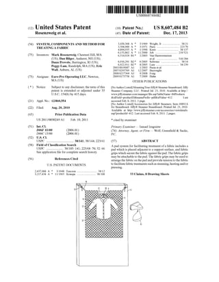
  • 1. (12) United States Patent Rosenzweig et al. USOO86O7484B2 (10) Patent No.: US 8,607,484 B2 (45) Date of Patent: Dec. 17, 2013 (54) SYSTEM,COMPONENTSANDMETHOD FOR 3:56 A : R s Sight, Jr......................... S5- ww. alS ....... TREATING AEABRIC 4,894.935 A * 1/1990 Kretz .............................. 38,137 6,153,862 A * 1 1/2000 Job ............................... 219,521 (75) Inventors: Mark Rosenzweig, Chestnut Hill, MA 6,514,924 B1* 2/2003 Van Hauwermeiren (US); Dan Bilger, Amherst, NH (US); et al. ....... ... 510,284 Dann Provolo, Barrington, RI (US); 6,910,291 B2 * 6/2005 Schwass ........................... 38/14 s s . . 6,922,911 B2 8/2005 Lam ................................ 34,239 Peggy Lam, Randolph, MA (US); Eric 2003, OO19087 A1 1/2003 Pasin et all Wall, Auburn, AL (US) 2007/0295769 A1 12/2007 Burroughs 2008, 0217364 A1 9/2008 Fong (73) Assignee: Euro-Pro Operating LLC, Newton, 2009/0173758 A1 T/2009 Hahn MA (US) OTHER PUBLICATIONS (*) Notice: Subject to any disclaimer, the term ofthis NoAuthorListed MountingYourJiffy(R)SteamerSteamboard.Jiffy patent is extended or adjusted under 35 Steamer Company, LLC. Printed Jul. 23, 2010. Available at http:// U.S.C. 154(b) by 415 days. www.jiffysteamer.com/manager/file.asp?tableName=tblProducts &idField-productID&namePrefix=pdf&idValue=412. Last (21) Appl. No.: 12/860,554 accessed Feb. 8, 2011. 1 page. No Author Listed Accessories for JiffyR. Steamers. Item #0892A (22) Filed: Aug. 20, 2010 for Steamboard. Jiffy(R) Steamer Steamboard. Printed Jul. 23, 2010. Available at http://www.jiffysteamer.com/accessories/viewdetails. (65) Prior Publication Data asp?productId=412. Last accessed Feb. 8, 2011. 2 pages. US 2011FOO3O249 A1 Feb. 10, 2011 * cited by examiner (51) Int. Cl. Primary Examiner— Ismael Izaguirre D6F 83/00 (2006.01) (74) Attorney, Agent, or Firm — Wolf, Greenfield & Sacks, DO6C (5/OO (2006.01) P.C. (52) U.S. Cl. USPC .................................. 38/141; 38/144; 223/61 (57) ABSTRACT (58) Field ofClassification Search A pad system for facilitating treatment ofa fabric includes a USPC .. . . .. 38/103-141; 223/6870, 52-66 pad which is placed adjacent to a Support Surface, and fabric Seeapplication file forcomplete search history. grips which securethefabricagainstthe pad.The fabricgrips maybeattachableto thepad. The fabric grips may beusedto(56) References Cited U.S. PATENT DOCUMENTS 2.437,084 A 3,217,434 A * 3, 1948 Esecson ............................ 38/12 * 1 1/1965 Konopa .......................... 38.108 14 arrangethe fabric on thepadandprovidetension to thefabric tofacilitatefabrictreatmentssuchassteaming,heatingand/or pressing. 33 Claims, 8 Drawing Sheets S. 19 XXXX S S Q S2 4 8X XX e 2 ::: 8 &S. 22-K &CC ser:XXXXs X.&KXXXXXXXXX{XXXXXXXX0s{XXXXXXXXX S&S S&SXMY 80
  • 2.
  • 3. U.S. Patent Dec. 17, 2013 Sheet 2 of8 US 8,607,484 B2
  • 4. US 8,607,484 B2Sheet 3 of8Dec. 17, 2013U.S. Patent FIG.2b
  • 6. US 8,607,484 B2Sheet 5 of 8Dec. 17, 2013U.S. Patent FIG. 4
  • 7. U.S. Patent Dec. 17, 2013 Sheet 6 of8 US 8,607,484 B2
  • 8. U.S. Patent Dec. 17, 2013 Sheet 7 of8 US 8,607,484 B2
  • 9. U.S. Patent Dec. 17, 2013 Sheet 8 of8 US 8,607,484 B2 POSITIONPAD POSITION FABRIC GRIPFABRICWITHFABRIC GRP SECURE FABRIC GRIP TREATFABRIC FIG. 7
  • 10. US 8,607,484 B2 1. SYSTEM, COMPONENTS AND METHOD FOR TREATING AEABRIC BACKGROUND Garment steamers are often used to Smooth wrinkles in clothing or other fabrics, and also as a way of freshening clothes between cleanings. Typically, a garment steamer releases steam toward a target fabric, and the Steam relaxes the fibers in thefabric. In some steamers,thesteam isemitted from a nozzle, and in other steamers, the steam is emitted fromholes inaflatmetal plate. Irons areoften usedtosmooth wrinkles in fabrics by heating the fabric and flattening the fibers with pressure applied by an iron plate. SUMMARY Embodimentsoftheinventionprovidedhereinaredirected to appliances, components, methods and systems in which a pad system is used for facilitating the treatment ofa fabric. According to one embodiment, a method of treating a fabric includesacts ofpositioningapadadjacentto a Support Surface, positioning a fabric adjacent to the pad such that at leasta portion ofthepadisbetweenthe fabricand thesupport Surface,andgrippingthefabric withafabricgrip.Themethod further includes securing the fabric grip Such that tension is applied to the fabric, and treating the fabric. According to another embodiment, a pad for arranging a garment adjacent to a Support Surface includes an exposed cloth layer, a rigid layer, a flexible backing layer, and a gar ment hangerholder. According to a furtherembodiment, a kitofparts includes a foldable pad capable of being positioned adjacent to a Support Surface and a plurality of fabric grips. The fabrics grips are configured to hold a fabric relative to the Support surface such that at least a portion of the foldable pad is capable ofbeing positioned between the fabric and the Sup port Surface. Furtherfeaturesandadvantages oftheembodimentsofthe present invention, as well as the structure of the various embodiments ofthe present invention are described in detail below with reference to the accompanying drawings. BRIEF DESCRIPTION OF DRAWINGS Theaccompanying drawings are not intended to be drawn to scale. Forpurposes ofclarity, notevery componentmaybe labeled in every drawing. In the drawings: FIG. 1 shows a perspective view ofa pad system fortreat ing a fabric; FIG.2a shows a cross-sectional view ofthe internal layer arrangement of a pad and a rigid insert according to one embodiment ofthe invention; FIG.2b shows the arrangement ofthe rigid inserts within the pad; FIG.3 shows a perspective view ofone type offabric care appliance for use with the pad system; FIG.4 showsasideview ofafabric careappliancepressing and applying steam to a fabric; FIG. 5 shows fabric grips applying tension to a fabric garment; FIG. 6 shows a perspective view ofone embodiment ofa fabric grip having a surfaceadapted to attach to thepad; and FIG. 7 shows a flow chartofa method oftreating a fabric. DETAILED DESCRIPTION OF INVENTION Various aspects ofthe invention are described below and shown in thedrawings.Theseaspectsoftheinvention maybe 10 15 25 30 35 40 45 50 55 60 65 2 used alone or in any Suitable combination with each other. Aspects ofthe invention are not limited in any way by the illustrative embodiments shown and described herein. In addition, itshouldbeunderstoodthataspectsofthe invention may beused alone or in any suitable combination with other aspects ofthe invention. Certain embodiments ofthe invention provided herein are directed to a pad system which may be used with fabric care appliances to freshen and press various fabrics with a hand held steam and/orheatapplicator. Accordingto oneaspect of the disclosure, a fabric may bepositionedandtensioned on a pad to facilitate the treatment ofthe fabric, for example the application ofsteam and/orheat to the fabric. Known garment SteamerSystems that apply only steam to fabrics can beuseful in many situations. Such steamers often includea handheld unit which is configured to deliver steam to a fabric via a steam nozzle or other steam outlet. These systems may include Swivel hangers and telescoping poles with mechanical clips for positioning fabrics in an opened out configurationtofacilitatesteamapplication. However, for Smoothing wrinkles and giving fabrics a crisp look, applica tion of steam alone may provide only temporary wrinkle reduction. In some cases, once the fabric dries, some ofthe wrinkles may reappear. Typical garment steamer systems do not provide backing Support ifthe user wishes to apply pres sure tothefabric, nordo they allow agarmenttobetensioned orstretched other than by gravitational forces. Applying tension to a fabric and/or providing a backing against which the fabric is pressed during steam and/orheat application may facilitate removal of wrinkles. In certain embodiments of the system disclosed herein, a fabric is arranged on a support surface, such as a vertical or slanted surfacepriorto fabric treatment. The fabric may beheld inan expanded configuration with fabric-gripping elements (e.g., fabric clips)bypositioningthefabric-grippingelements such thatthey applytensionto thefabric.That is, thefabric may be held in a configuration otherthan how the fabric would natu rally hang when Supported only from its top. Tension beyond that sufficient to merely hold the fabric in an expanded State may be applied with the clips to stretch and/orflattenthefabric. InSuchanarrangement,Steamand/or heat relaxes the fibers in the fabric and the tensioning and/or pressing ofthe fabric may stretch the fibers into a flattened and/or aligned state. The vertical or slanted Support Surface allowsthefabrictobepressedwithgreaterforcethancouldbe applied to a hanging fabric that has no backing Support. In alternative embodiments, a pad is arranged on a horizontal Support Surface, and fabric grips are used to hold the fabric relative to the horizontal support surface with at least a por tion ofthepad between the fabric and thehorizontal support Surface. A padsystem fortreatingfabrics is shown in FIG.1. Apad 10 ispositionedadjacentto a vertical SupportSurface 12 Such as a door, wall, or other suitable surface. Pad 10 may be flexibleorrigid. Forinstance,a flexiblepadcouldbeusedfor travel applications. In someembodiments, pad 10 is made of fabric and is foldable for packing and storing. An insert formed with material that is more rigid than the fabric ofpad 10 may be included in some embodiments to provide a flat Surface when the Support Surface is uneven, and the insert may be removable and/or rollable forpacking and storing. Pad 10 may be positioned adjacent to vertical support surface 12 with straps 14 which extendfrom pad 10,although other positioning elements may be used such as hooks, rods, hangers, nails, Screws, adhesives, or otherSuitable fasteners. Straps 14 may be permanently attached to pad 10 in some embodiments.Straps 14 mayincludeadjustablebuckles 19in
  • 11. US 8,607,484 B2 3 Some embodiments to adjust strap length for positioning of pad 10 adjacent to vertical surface 12 at a desired height. Insomeembodiments, fabric 16 isagarmentwhich maybe positioned adjacent to pad 10 using a garment hanger9 that engages a hangerholder20. Hanger holder20 may include a 5 rod 21, an eye screw, a reinforced cut-out in pad 10, orother suitable hangerholder. One or more fabric grips 22 may be usedto arrangeand/or tension fabric 16 priorto applying steam and/orheat. Fabric grips 22 are adapted to grip fabric 16 without damaging the material. Inadditiontogripping fabric 16, fabricgrips22also may be constructed and arranged to be attached directly to pad 10. Thecombinationofgrippingthefabric 16andattach ing the fabric grip 22 directly to pad 10 allows a user to arrange/tension fabric 16 while the fabric is in a substantially 15 vertical orientation. If desired, the fabric grips 22 may be attached to pad 10 at multiple selected locations to arrange andtensionfabric16 inmultiplelocationsand directions.The fabric grips22 also may beusedto hang fabric 16adjacentto pad 10, for example, instead ofusing a hanger Such as gar ment hanger9. Fabric grips 22 may selectively attachable to pad 10by auser,orin someembodiments,oneormorefabric grips may be pre-attached to pad 10. Once Suitably arranged and tensioned on pad 10, a fabric care appliance 80 may be used to apply steam and/orheat to fabric 16. Dependent upon the type offabric care appliance employed,thisprocess mayincludepressingfabric16against pad 10 to enhance wrinkle removal. As shown in FIG. 2a, in some embodiments, pad 10 may include a layerofquilted terry cloth 11 and a layer ofmesh padding 13, and may include one or more layers of water resistant nylon 15 as a backing material. Pad 10 may incor porate other moisture and/or heat resistant materials to pro vide additional protection to the Support Surface. One or more rigid inserts 17 may be added to pad 10 to provide a smooth support surfacewhen pad 10 is placed over an uneven Surface. Suchasapanel door,forexample. Insome embodiments, rigid inserts 17 may provide additional heat and/or moisture protection for the Support Surface. Rigid inserts 17 may have a square shape, a rectangular shape, or any otherSuitableshape. Theinserts maybeany Suitablesize, for example 11 inches by 11 inches with a thickness of approximately 0.8 mm. The inserts may be constructed of polypropylene, polycarbonate, acetate, orany Suitable com bination thereof. Ofcourse, othersuitable materials or mate- 45 rialcombinations mayusedtoformtherigidinsertsaslongas the material can withstand the heat, moisture and/or other factors that may be associated with typical use. Forexample, a 0.8 mm thickness ofpolypropylene is water-resistant and heat-resistant in the embodiment shown in FIG. 2a because 50 during typical use with steam and heat application, the rigid insert maintains its structural integrity. In certainembodiments, suchastheembodimentshown in FIG. 2a, rigid insert 17 is held within pad 10 between two opposing layers ofnylon 15. The inserts may be positioned 55 between other layers ofapad, or may bepositioned on a rear Surface of a pad such that the inserts are not positioned between layers. Rigid inserts 17 (orothercomponentsofpad 10) may include magnetic material So that fabricgripshaving magnets can be attached to pad 10. FIG. 2b shows the arrangement of a plurality of rigid inserts 17, depicted by dashed lines, being held in pad 10. In the embodiment shown in FIG.2b, eight rigid inserts 17 are arranged in a rectangular two by fourpattern across Substan tially theentireareaofpad 10. Thisparticulararrangementof 65 inserts 17 (among others) allows pad 10 to be folded into a portable size with the rigid inserts remaining in the pad. In 10 25 30 35 40 60 4 other embodiments, rigid inserts 17 may be arranged in a differentpatternand/ormaybearrangedonlyacrossaportion ofthe area ofpad 10. Removablerigidinserts maybeprovidedso that theinserts can be removed for laundering ofthe pad. In some embodi ments, rigid inserts 17 may be inserted into openings 18 for retaining sleeves, pockets or other receptacles (not shown) arranged on pad 10. Openings 18 may includehookand loop fasteners or other closure elements to aid in retaining the inserts in the receptacles. Ofcourse, in Some embodiments, rigid inserts 17 may be permanently held within pad 10. Oneembodimentofa fabric care appliance 80 which may beusedwith thepad system disclosedhereinisshownin FIG. 3. Fabric care appliance80 has an operating head 82 includ ing a heating bar 84 and a fabric covered steam outlet 86. A handgrip area 88 is positionedbelow operating head82 with convenientaccess toatrigger89whichauseractuatestoemit steam from the steam outlet. Bypositioningheatingbar84(orotherheatingSurface) on thesameappliancebodyasasteam outlet, asausermovesthe handheld unitacross the Surface ofa fabric, steam is applied to the fabric, followed by a pressingaction ofheating bar84 against the fabric 16. This dualaction can beachieved with a single pass of fabric care appliance 80 when the appliance body is moved in a direction where the steam outlet leads heating bar 84. Ofcourse in some embodiments, a user may apply steam to an area of a fabric, and then in a separate motion, return tothesame fabric areaandapplyheatwith the heating bar. It should be understood that the fabric care appliance 80 described herein is only one of many fabric care appliances that could beused with the current system. It is possible that an appliance might apply only steam or only heat. Further, heating bar 84 and fabric covered steam outlet 86 may be reversed in position. Fabric care appliance 80 may employ more than one heating Surface and/or more than one steam outlet. In someembodiments, a fabric care appliance may be configured to treata fabric in otherSuitable manners, such as by applying a fluid, a spray, oragas, whetherheated, cooled orat ambient temperature. As shownin FIG.4,afabriccareappliance80 maybeused to apply steam 90 to a target fabric 16 while simultaneously pressing fabric 16 with aheating Surface, such as heatingbar 84.Asdiscussedfurtherabove,tohelptheuserapplypressure to fabric 16 with heating bar84, fabric 16 is arranged on pad 10 which is interposed between fabric 16 and a vertical sur face 12 Such as a door. In addition to providing abacking for steaming and pressing, pad 10 protects fabric 16 and the vertical surface 12. FIG. 5 illustrates a fabric 16, in this case a shirt, arranged andtensionedusing fabric grips 22. Fabric grips 22 may grip fabric 16 using a clip as shown by fabric grip 22 positioned aroundtheedgeoffabric 16. Friction from pressing fabric 16 againstpad10,forexamplewitha magnet23,canholdand/or tension the fabric. Othersuitable elements configuredto grip fabric 16 maybeused.Arrows 24denotedirections oftension applied to fabric 16 by fabric grips 22 as a result of the particulararrangement shown in FIG. 5. Oneembodimentofa fabric grip 22 is shown in FIG. 6. A clip26 includesjaws30whicharebiasedclosedwithaspring or other resilient arrangement. Jaws 30 are adapted to grip fabrics without damaging the material. Clip 26 additionally has a pad-engagement Surface 28 adapted to attach to a cor respondingsurfaceofpad 10. FIG. 5 showsone embodiment wherein the pad-engagement Surface 28 comprises a hook andloop fastener material(e.g.,Velcro(R)onamajority ofthe surface. The term “hook and loop fastener material is
  • 12. US 8,607,484 B2 5 intended to include either ofonly “hook material' and only “loop material’, orboth of“hook material and “loop mate rial'. Itshouldbe recognized thatin someembodiments, only a portion ofone side offabric grip 22 includes pad-engage mentmaterial,whileinotherembodiments theentiretyofone side of fabric grip 22 is adapted to be a pad-engagement surface. In otherembodiments, attachmentsurface28 offab ric grip 22 may compriseany suitableelements configuredto attach fabric grip 22 to pad 10, includingbut notlimited to, a magnet or a mechanical fastener Such as a clip ora peg and hole arrangement. In some embodiments, fabric grips 22 have pad-engage ment Surfaces on both sides or more than two sides. Such an arrangement may facilitate rapid treatment of at least two Surfaces ofa garment. Forexample,a method oftreating two Surfaces may include acts of treating a first Surface of the garment which is held by at least one fabric grip 22, disen gagingthefabricgrip22fromthepad 10 withoutdisengaging the garment from the fabric grip 22, flipping or rotating the clothing to present a second, untreated Surface, re-engaging the fabric grip 22 to the pad 10, and treating the second garment Surface. In some embodiments, having dual pad engagement Surfaces on the fabric grip 22 may allow a gar ment to be folded or bent with respect to the pad 10 to facilitate quick treatments ofvarious areas ofthe garment. FIG. 7presents a flow chart 60 ofa methodofusinga pad system to treat a fabric. The method includes an act 62 of positioning a pad adjacent to a Support Surface. An act 64 includes positioning a fabric adjacent to the pad such that at leasta portionofthepad is positionedbetween the fabricand thesupportsurface. Thefabric isgrippedwith afabric grip in an act 66. In an act 68, the fabric grip is secured such that tension is applied to the fabric. To secure the fabric grip, the fabric grip may be attachedto thepad, or may be attached to the door, or may be attached through the pad to the door. In Some embodiments, as discussed further above, the attach ment ofthe fabric grip to the pad may be achieved using a pad-engagementSurfaceonthefabricgrip. This pad-engage ment Surface may includea hookand loop fastener material. An act 70 includes treating the fabric, such as by applyingat leastoneofsteam andheatto thefabric, forexample. Itshould be understood that this method is not necessarily limited by the order in which the acts are recited. A kit ofparts can be supplied to facilitate methods dis closedherein ofusing apad system fortreatinga fabric. The kit ofparts includes, but is not limited to, a pad and one or more fabric grips. The pad is positionable adjacent to a Sup portSurfaceSuchasadoor,wall,orotherSuitableSurface,and the pad may be foldable. The fabric grips are configured to hold a fabric relative to the support surface such thatat least a portion ofthe pad is positioned between the fabric and the Support Surface. The pad also may have an engagement Sur face that is adapted to attach to the fabric grips. Each fabric grip may include an engagement Surface that is adapted to attachtothepad.Thekitofpartsalso may includeattachment elements, suchasStraps, which are configuredandadaptedto attach the pad to the Support Surface. The attachment ele ments maybeselectivelyattachabletothepadorpermanently attachedto the pad.The various parts ofthe unit ofparts may be packaged in any convenient manner and may be sold individuallyin separatepackagesortogetherinasinglepack age. Instructions forthe useofthe componentparts ofthiskit may be available through a set ofprinted instructions pack aged with thekit, on a digital readable media packaged with the kit, on the internet, or may be distributed by any other readable means. 10 15 25 30 35 40 45 50 55 60 65 6 For purposes herein, the terms "engage”, “engaged'. “engagement”,“attach”,“attached and“attachment”referto directconnectionsandattachments, indirectconnections and attachments, andoperativeconnectionsandattachments. For purposesherein,theterm“adjacent includesbeingincontact with an element or in close proximity to an element. Two elements may be adjacent to one another even if a third element is located between the two elements. It should be understood that acts listed in the claims do not necessarily have to be performed in the order recited unless an order of acts is specifically recited. Having thus described several aspects ofembodiments of this invention, it is to be appreciated various alterations, modifications, and improvements will readily occurto those skilled in the art. Such alterations, modifications, and improvements are intended to be part ofthis disclosure, and areintendedtobewithinthespiritandscopeoftheinvention. Accordingly, the foregoing description and drawings are by way ofexample only. What is claimed is: 1. A method oftreating a fabric comprising acts of (a) positioning a pad adjacent to a Support Surface; (b)positioninga fabricadjacenttothepadsuch thatatleast aportionofthepadisbetweenthefabric andthe support Surface; (c) gripping the fabric with a fabric grip: (d) securing the fabric grip Such that tension is applied to the fabric, wherein securing the fabric grip such that tension is applied to the fabric comprises attaching the fabricgriptothepad,whereinattachingthefabricgripto the pad comprises attaching the fabric grip to the pad with a hook and loop fastening material which is included on the fabric grip; and (e) treating the fabric. 2. The methodofclaim 1, wherein attachingthefabric grip to the pad in act (d) comprises pressing a pad-engagement Surface ofthe fabric grip against the pad. 3. The method ofclaim 1, wherein (c) comprises gripping the fabric with a plurality offabric grips, and (d) comprises attaching the plurality offabric grips to the pad. 4. The method ofclaim 1, wherein (a) comprises position ing the pad adjacent to a vertical Support Surface. 5. The method of claim 1, wherein the pad comprises a hanger holder and (b) comprises engaging a hanger with the hanger holder. 6. Themethod ofclaim 1, wherein (a)comprises position ing a pad which includes a flexible cloth layer. 7. The method ofclaim 1, wherein (a)comprises position ing a pad which includes a terry cloth layer and a water resistant backing material. 8. The method ofclaim 1, wherein (a)comprises position ing a pad which includes a cloth layer and a layer of rigid Support material. 9. The method ofclaim 1, wherein (e) comprises pressing the fabric. 10. A method oftreating a fabric comprising acts of: (a) positioningapadadjacenttoa Support Surface wherein positioning a pad adjacent to a Support Surface com prisespositioningapadwhichincludes acloth layerand a layer of rigid Support material, wherein the layer of rigidSupport material comprisesaplurality ofrigid Sup port material sections positioned such that the pad is foldable; (b)positioninga fabricadjacenttothepadsuch thatatleast aportionofthepadisbetweenthefabric andthe support Surface; (c) gripping the fabric with a fabric grip:
  • 13. US 8,607,484 B2 7 (d) securing the fabric grip Such that tension is applied to the fabric, and (e) treating the fabric. 11. Themethodofclaim 10, wherein (d)comprisesattach ing the fabric grip to the pad with a hook and loop fastening material which is included on the fabric grip. 12. The method ofclaim 10, wherein (a) comprises posi tioning a pad which includes a terry cloth layerand a water resistant backing material. 13. A pad for arranging a garment adjacent to a Support Surface, the pad comprising: (a) an exposed cloth layer, (b) a rigid layer, wherein the rigid layer comprises a plu rality of rigid sections positioned such that the pad is foldableandthepadcomprisesapluralityofreceptacles, each configured to hold at least one rigid section; (c) a flexible backing layer, and (d) a garment hangerholder. 14. The pad ofclaim 13, further comprising at least two attachment loops, each loop being configured to engage a cornerofa doorto hold the pad adjacent to the door. 15. A pad for arranging a garment adjacent to a Support Surface, the pad comprising: (a) an exposed cloth layer: (b) a rigid layer, (c)a flexible backing layer; (d) a garment hangerholder, and (e) at least two attachment loops, each loop being config uredto engageacornerofa doortoholdthepadadjacent to the door. 16. Thepadofclaim 15, wherein the rigid layercomprises a plurality of rigid sections positioned such that the pad is foldable. 17. The pad of claim 16, wherein the pad comprises a plurality ofreceptacles, each configured to hold at least one rigid section. 18. A pad for arranging a garment adjacent to a Support Surface, the pad comprising: (a) an exposed cloth layer, (b) a rigid layer, (c) flexible backing layer; (d) a garment hangerholder, and (e) a mesh layer between the exposed cloth layer and the flexible backing layer. 19. A kit ofparts comprising: (a)a foldablepadthat ispositionableadjacentto a Support Surface; and (b) a plurality offabric grips, wherein the fabric grips are attachable to the foldable pad, wherein each fabric grip includesaclipandapad-engagementSurfaceconfigured to engage with the foldable pad, wherein the pad-en gagement Surface comprises a hook and loop fastener material, and the foldable pad comprises an exposed material which is engageable with the hook and loop fastener material of the pad-engagement Surface, the fabric grips being configured to holda fabric relativeto 5 10 15 25 30 35 40 45 50 55 8 the Support Surface Such that at least a portion of the foldable pad is positioned between the fabric and the Support Surface. 20. The kit ofparts ofclaim 19, wherein each fabric grip includesapad-engagementSurfaceonatleasttwo sides ofthe fabric grip. 21.Thekitofpartsofclaim 19, furthercomprisinga fabric care appliance that has a heatable pressing Surface. 22.The kitofparts ofclaim 19, furthercomprisingattach mentelementsconstructedandarrangedtoattachthefoldable pad to the Surface. 23. The kit ofparts ofclaim 22, wherein the attachment elements are constructed and arranged to attach the foldable pad to a vertical Support Surface. 24. A kit ofparts comprising: (a) a foldablepadthat is positionableadjacenttoa Support Surface; (b) a plurality offabric grips, the fabric grips being con figured to hold a fabric relative to the support surface such that at least a portion ofthe foldable pad is posi tioned between the fabric and the support surface; and (c)a plurality ofselectively removable rigid inserts held in receptacles within the foldable pad. 25.Thekitofpartsofclaim 24,whereinthefabricgripsare attachable to the foldable pad. 26. The kit ofparts ofclaim 24, wherein the pad-engage mentSurfacecomprisesahookandloopfastenermaterialand the foldable pad comprises an exposed material which is engageable with the hook and loop fastener material ofthe pad-engagement Surface. 27. A method oftreating a fabric comprising acts of: (a)positioningapadadjacenttoaSupportSurface,wherein positioning a pad adjacent to a Support Surface com prises positioning a pad which includes a terry cloth layer and a water-resistant backing material; (b)positioninga fabricadjacenttothepadsuch thatatleast aportionofthepadisbetweenthefabric andthe support Surface; (c) gripping the fabric with a fabric grip: (d) securing the fabric grip Such that tension is applied to the fabric; and (e) treating the fabric. 28.The methodofclaim 27, wherein (d)comprisesattach ing the fabric grip to the pad. 29.The methodofclaim 27, wherein (d)comprisesattach ing the fabric grip to the pad with a hook and loop fastening material which is included on the fabric grip. 30. The method ofclaim 27, wherein (c) comprises grip ping the fabric with a plurality of fabric grips, and (d) com prises attaching the plurality offabric grips to the pad. 31. The method ofclaim 27, wherein (a) comprises posi tioning the pad adjacent to a vertical Support Surface. 32. The method ofclaim 27, wherein (a) comprises posi tioning apad which includesacloth layeranda layerofrigid Support material. 33. The method ofclaim 27, wherein (e)comprises press ing the fabric.