SlideShare a Scribd company logo
1 of 7
Download to read offline
United States Patent 19
Schaeffer et al.
54
75)
73)
21
22
51
52
58
56
METHOD FOR CHROMUM COATNGA
SURFACE AND TAPE USEFUL IN
PRACTICING THE METHOD
Inventors: Jon C. Schaeffer, Milford; Mark A.
Rosenzweig, Hamilton; Warren D.
Grossklaus, Jr., West Chester, all of
Ohio; Robert J. Van Cleaf,
Greenwood, S.C.; Frederick S.
Kaempf, Delanson, N.Y.
Assignee: General Electric Company, Cincinnati,
Ohio
Appl. No.: 409,395
Filed: Mar 24, 1995
Int. Cl. ... CO97/02
U.S. Cl. ................... ... 428/344; 428/354
Field of Search ..................................... 428/343,354,
428/344
References Cited
U.S. PATENT DOCUMENTS
4004,047 1/1977 Grisik ...................................... 427/142
IIIUS005674610A
11 Patent Number: 5,674,610
45 Date of Patent: Oct. 7, 1997
4,726,101 2/1988 Draghi et al. ...................... 29/56.8 B
Primary Examiner-Jenna Davis
Attorney, Agent, or Firm-Andrew C. Hess; David L.
Narciso
57 ABSTRACT
Chromium is deposited on a surface using a coating tape
having a source layer including a powdered source of
chromium, a solid reactant that reacts with solid chromium
at elevated temperature to produce a gaseous chromium
containing compound, an inert powder dispersed with the
powdered source of chromium, and a binder. Preferably, a
porous media layerincludingaporous media material and a
binder is affixed to the source layer. The coating tape is
positioned adjacent to the surface ofthe substrate, with the
porous media layer, where present, in contact with the
surface. The coating tape and substrate are placed into a
container, and the container is heated to elevated tempera
tureinanon-oxidizingatmosphere.Thegaseouschromium
containing compound is produced and chromium is depos
itedfromthe gaseous chromium-containing compound onto
the surface of the substrate.
16 Claims, 2 Drawing Sheets
U.S. Patent Oct. 7, 1997 Sheet 1 of 2 5,674,610
4-O 42 44
PROVIDE
METALLC
SUBSTRATE
SUPPLY
COATING
TAPE
POSITION COATING
TAPE ADJACENT
TO SUBSTRATE
PLACE COATING
APE AND
SUBSTRATE INTO
SEALED CONTAINER
HEAT COATING
TAPE AND
SUBSTRATE
FG. 3
U.S. Patent Oct. 7, 1997 Sheet 2 of2 5,674,610
YNYNYNYNYNYNYNY YNYNYNYNYNY
5,674,610
1
METHOD FOR CHROMUM COATING A
SURFACE AND TAPE USEFUL IN
PRACT CING THE METHOD
BACKGROUNDOFTHEINVENTION
This invention relates to the coating of the surface of a
metallic substrate, and, more particularly, tothe application
of a chromium coating to the surface.
Inanaircraftgasturbine(jet) engine,airis drawn intothe
front of the engine, compressed by a shaft-mounted
compressor,andmixedwithfuel.Themixtureisburned,and
the hot exhaust gases are passed through a turbine mounted
on the same shaft. In the turbine, the flow of gases is
deflected by sets ofturbine vanes to impinge upon a series
of turbine blades mounted to turbine wheels supported on
the shaft. The flow ofgas turns the turbine, which turns the
shaftandprovidespowerto the compressor.The hotexhaust
gases flow from the back ofthe engine, driving it and the
aircraft forwardly.
The hotter the exhaust gases, the more efficient is the
operation ofthejetengine.Thereisthus an incentiveto raise
the exhaust combustion gas temperature. The maximum
temperature ofthe combustion gases is normally limitedby
the materials used tofabricatetheturbine blades and turbine
vanes of the turbine, upon which the combustion gases
directlyimpingewhenthey areattheirhottesttemperatures.
In currentpractice, the turbine blades and turbine vanes
are made of nickel-base or cobalt-base superalloys. The
superalloys are selected and processed to be strong, creep
resistant, and fatigue resistant. However, the superalloys
themselves arenothighlyresistanttoprogressivedamageby
oxidation, hot corrosion, and erosion when exposed to the
flowing hot combustion gases. These damage mechanisms
normally establish the maximum operating lives of the
turbine blades and turbine vanes. To extend the operating
lives, the turbine blades and turbine vanes are coated with
various types of coatings that protect them from oxidation,
corrosion, and erosion.
The turbine blades and vanes are arranged in stages
according to the pressure and temperature of the exhaust
gases that impinge upon them. Different coatings are used
for the components of the various stages. In the high
pressure stages, thermal barrier coating systems or
aluminum-containing coatings are employed. In the low
pressure stages, chromium coatings are favored.
The coatings are applied during the fabrication of the
turbine components.Thecoatings degrade duringservice as
a result ofcontinued exposure to the hot exhaust gases and
temperature changes during the operating cycles of the
engine. The coatings can also be damaged during handling
in the course ofmanufacturing, installation, and inspection.
In all ofthese circumstances, repair ofthe coatings maybe
required.
Various techniques have been proposed to repair the
chromium coatings of the low-pressure turbine blades and
5
10
15
25
30
35
45
55
turbine vanes.These repair techniques include,for example, .
overchromiding by applying a new chromium coating over
the entire old coating, applying chromium metal in a slurry
or tape followed by sintering, and brush plating. Only the
overchromidingprocesshas metwithanydegree ofsuccess.
This approach is operable, but generally must be accom
plished by returning the component to the original
manufacturer, which can be inconvenient and costly.
There is a need for a better approach to applying a
chromium coating to a metallic surface, particularly under
65
2
field-repair conditions. Suchanapproach wouldbe ofvalue
fortherepairofaircraftturbine components, butwouldalso
be useful in a variety of other situations where chromium
coatings are used. The present invention fulfills this need,
and further provides related advantages.
SUMMARY OF THE INVENTION
This invention provides a method for applying a chro
mium coatingto the surface ofa substrate.The coating can
be deposited locally, making the approach ideal for the
repair of damaged components. The deposition procedure
requires only a furnace and does not require complex
coating equipment.The coating can therefore be appliedin
field repairs without returning the component to its manu
facturer. The invention also provides a convenient and
economical coatingtape that is used in the coatingprocess.
Asusedherein,a"chromiumcoating”,sometimes termed
a "chromide coating” in the art, is a coatingwhich contains
chromium and thatis applied to the surface ofthe substrate
inexcess ofany amountthatmaybepresentinthesubstrate
alloy. During service,the chromium coatingis typically not
purechromium,butincludesa concentrationofthe elements
presentinthe substrateasaresultoftheinterdiffusion ofthe
coatingand the substrate. Even wherethe chromium coating
asinitially applied is substantially pure chromium, interdif
fusion with the substrate typically occurs rapidly as a result
of exposure at elevated temperatures. Such interdiffusion
during application ofthe coating or thereafter during a heat
treatment or service is acceptable and desirable to increase
adherence of the coating to the substrate.
In accordance with the invention, a method ofdepositing
chromium ona surfaceofa metallic substrate comprisesthe
stepsofprovidingametallicsubstratehavinga surface,and
supplying a solid source of chromium and a solid reactant
that is operable to react with solid chromium at elevated
temperature to produce a gaseous chromium-containing
compound. The method further includes heating the solid
source of chromium and the solid reactant to elevated
temperature to produce the gaseous chromium-containing
compound, and contacting the gaseous chromium
containing compoundtothe surface ofthe substrate,where
upon chromium is deposited from the gaseous chromium
containingcompoundontothe surfaceofthe substrate. Care
istakentoremoveandpreventthe re-formationoftenacious,
adherentsurface oxides on the substrate thatwould interfere
with the deposition ofthe chromium coating.
Theinventionispreferablypracticed usingacoatingtape
to supply the reactants in a convenient form and a closed
reactor to prevent the escape of the chromium-containing
gas. In accordance with this aspect of the invention, a
method of depositing chromium on a surface of a metallic
substrate comprises the steps of providing a metallic sub
strate having a surface and supplying a coating tape. The
coatingtape comprises a source layerincludingapowdered
source ofchromium, a solid reactantthatis operableto react
with solid chromium at elevated temperature to produce a
gaseous chromium-containing compound, an inert powder
dispersed with the powdered source of chromium, and a
binder. The method further includes positioning the coating
tape adjacent to the surface of the substrate, placing the
coating tape and substrate into a container and sealing the
container, and heating the coating tape and the substrate to
elevated temperaturewithinthesealed container.Again,care
is taken to avoid surface oxides on the substrate that could
interfere with the chromium deposition.
The coatingtape can further include aporous media layer
of a porous media material affixed to the source layer. The
5,674,610
3
porous media layer physically separates the source layer
from the substrate. Solid reactant material from the source
layer is prevented from contacting and possibly reacting
with the substrate, and the inert powder in the source layer
cannotbecome embeddedintothe substrate asthe chromium
is deposited. Chromium-bearing gas from the source layer
passesthroughtheporousmedialayertoreachthesubstrate.
The porous media material is typically a mixture ofan inert
powdered material and a binder. When it is used, the
two-layertape structure is positioned with theporous media
layer in contact with the substrate.
The present invention also extends to the coating tape,
including both the one-layer embodiment having only the
source layer and the two-layer embodiment having the
source layer and the porous media layer.
The source layer is preferably formed of a mixture of
powdered chromium, a solid halide such as ammonium
fluoride or ammonium chloride as the Solid reactant (also
sometimes termed an "activator”), an Oxide powder such as
chromium oxide powder mixed with the powdered chro
miumtopreventitfrom agglomeratingandsintoting,andan
organicbinder.Theporous media layer ispreferably formed
of a mixture ofa metallic oxide such as aluminum oxide or
chromium oxide and a binder, or a ceramic gauze. In each
type of tape, the organic binder is present to bind the
constituents together in the tape during manufacture,
shipment, storage, and placement of the tape. The binder
vaporizes or burns away as the tape is heated.
The use of the coating tape that produces a gaseous
chromium-containingcompoundinthepreferredapplication
process is a particularly convenient approach to depositing
the chromium onto the surface of the substrate. It is not
necessary to apply a chromium vapor overpressure to the
entire partbeingchromided.The chromiumin thetape is not
melted, so that there is no risk ofthe unintentional deposi
tion of chromium masses on the substrate which would
adversely affect its airfoil performance. The approach
requires only that the tape be applied to the surface of the
substrate, the substrate and applied tape be placed into a
container, and the substrate and applied tape be heated to a
temperature sufficient that the reaction and deposition can
OCC.
Other features and advantages of the present invention
will be apparent from the following more detailed descrip
tion ofthe preferred embodiment, taken in conjunction with
the accompanying drawings, which illustrate, by way of
example, the principles of the invention.
BRIEF DESCRIPTION OF THE DRAWINGS
FIG. 1 is a perspective view ofa gas turbine component;
FIG. 2 is a sectional view through the component of FIG.
1, taken generally along line 2-2, illustrating a chromium
coating on the surface ofthe component;
FIG. 5 is a block diagram of one embodiment of the
approach of the invention;
FIG. 4 is an elevational view ofa one-layer coating tape;
FIG. 5 is an elevational view of atwo-layer coating tape;
FIG. 6 is a schematic sectional view illustrating one
embodiment of the application of the coating tape to the
surface of the component; and
FIG. 7 is a schematic sectional view illustrating a second
embodiment of the application of the coating tape to the
surface ofthe component.
DETALED DESCRIPTION OF THE
PREFERRED EMBODMENTS
FIG. 1 depicts a componentofa gas turbine engine such
asaturbineblade orturbinevane,andinthis caseis depicted
5
10
15
25
30
35
45
50
55
60
65
4
asaturbine blade20.Theturbineblade 20 includes an airfoil
22 againstwhich the flow ofhotexhaustgas is directed.The
turbine blade 20is mountedtoaturbine disk(not shown) by
a dovetail 24which extends downwardly from theairfoil 22
and engages a sloton theturbine disk.Aplatform26extends
longitudinally outwardly from the area where the airfoil 22
is joined to the dovetail 24. A number of cooling channels
desirably extendthrough the interioroftheairfoil22, ending
in openings 28 in the surface of the airfoil 22. A flew of
cooling air is directed through the cooling channels, to
reduce the temperature of the airfoil 22.
FIG. 2 illustrates in a section through the airfoil 22 a
chromium coating 30 deposited upon a surface 31 of the
turbine blade 20, which thereby acts as a substrate 32. The
substrate 32 may beformed of any operable material, but a
preferred base metal from which the substrate 32 is formed
is a nickel-base superalloy such as Rene 77, Rene 80, or
Rene 108. The preferred superalloy substrate is Rene 77.
which has a nominal composition, in weight percent, of 15
percent cobalt, 14.2 percent chromium, 4.3 percent
aluminum, 3.4 percent titanium, 4.2 percent molybdenum,
balance nickel and trace elements.
The chromium coating 30, as initially deposited upon the
substrate 32, is typically continuous with a thickness of
about 0.0005 to about0.0015 inches, nominally about0.001
inches. However,the continuous coating may be interrupted
at aflaw 34, where the coating 30 is partially or completely
(asillustrated) removedfrom the surface 31 ofthe substrate
32. Where present, the chromium coating 30 protects the
substrate 32 from damage by oxidation, hot corrosion, and
erosionby thehotexhaustgas.Where the chromiumcoating
30 is removed at a flaw 34, the hot exhaust gas can contact
the unprotected substrate32and quickly damageitbythese
mechanisms.
Flaws 34 occasionally occur due to damage during
manufacturing, handling, installation, or service. Flaws can
be detected duringinspections.The preferred application of
the present invention is to repair such flaws 34. The inven
tionwill be described in relation tothe use ofa coatingtape
to make the repair, because such a tape is convenient for
field repairs.
Amethod forpracticing the invention is depicted in FIG.
3. A metallic substrate 32 is provided, numeral 40. The
metallic substrate may be a turbine blade or turbine vane,
another gas turbine component, or other article. The only
limitation on the choice ofthe metallic substrate is that it be
suitable for the application of a chromium coating. The
surface of the substrate is cleaned of organic residue and
oxidesby conventional cleaningtechniques.Thepresence of
tenacious oxides on the surface of the substrate interferes
with the subsequent chromium deposition.
A coating tape 60 is supplied, numeral 42. Two embodi
ments ofthe coating tape 60 are illustrated in FIGS. 4 and
5. In a one-layer coating tape embodiment of FIG. 4, there
is a single source layer 62. In a two-layer coating tape
embodiment of FIG. 5, there is a source layer 62 and a
porous media layer 64. Additionally, there may be adhesive
layers as needed andwhich willbe described subsequently.
(The adhesive layers are not counted in the terminology
“one-layer" and “two-layer”, inasmuch as the presence and
type of the adhesive layers can be varied for different
applications.)
The source layer 62 is a mixture of a solid powdered
source ofchromium,a solid reactantthatis operableto react
with solid chromium at elevated temperature to produce a
gaseous chromium-containing compound, an inert powder
5,674,610
5
dispersed with thesolidpowdered source of chromium,and
abinder.Preferably,thesolidpowderedsourceofchromium
is chromiumpowder,typically-100mesh,high-puritychro
mium powder.
Preferably,the solidreactant (also termed an “activator")
is a solid halide compound, such as ammonium fluoride or
ammoniumchloride.Preferably,theinertpowderisanoxide
powder such as chromium oxide powder, typically of a size
of -400 mesh. The inert powder serves to prevent the
chromium powderfrom sintering and densifying duringthe
subsequent heating step, which would prevent the
chromium-containing gas from reaching the substrate.
Preferably,thebinderis anorganicbindersuchasanacrylic
S.
Even more preferably, the source layer 62 is prepared by
mixing from about 60 to about 90 parts by weight of
chromium powder and from about 5 to about 39 parts by
weight of chromium oxide powder, and then adding to this
mixture from about 1 to about 5 parts by weight ofammo
nium fluoride or ammonium chloride. Most preferably, the
Source layer 62 includes about 89 parts by weight of
chromium powder, about 10 parts by weight of chromium
oxide powder, and about 1 part by weight of ammonium
fluoride,withwhich the binderis mixed.Typically,about85
parts by weight ofthis mixture is mixedwith up to about 15
parts by weight of the binder, to form a mixture with a
suitable consistency for forming the source layer.
Theporous media layer64, usedinthetwo-layer embodi
ment of FIG. 5, is made ofan inert material through which
the chromium-containing gas passes but does not deposit
upon. Theporous media layer 64 can bea ceramicgauze or
the like.Theporous medialayer64 canalsobea mixtureof
a ceramic powder, such as aluminum oxide or chromium
oxide,andabinder. In thelattercase,theporous medialayer
64 is a mixture ofabout 85 parts by weight ofthe ceramic
powder and about 15 parts by weight ofan organic binder
such as an acrylic resin.
The source layer 62 and the porous media layer 64 are
separately manufactured by known processes for the fabri
cation of such layers. In each case, the constituents are
mixedtogetherandformedintoa layerby extrusion, rolling,
a doctorblade, orthe like.The source layer 62is preferably
fromabout0.010toabout0.015inches thick,and theporous
media layer 64ispreferablyfromabout0.015 toabout0.025
inches thick, as fabricated. In a working embodiment, the
source layer 62 was 0.013 inches thick And the porous
media layer64was 0.020inches thick.Alternatively,forthe
two-layercoatingtape 60 ofFIG. 5,the source layer 62and
the porous media layer 64 can be individually mixed, and
thereafter co-extruded, co-rolled, or the like to produce the
two-layered tape.
Afirst adhesive layer 66 is preferably provided to fix the
coatingtape 60to thesubstrate32. Inthe one-layerembodi
ment ofFIG. 4,thefirstadhesive layer66isprovidedon one
side ofthe source layer 62. In the two-layer embodiment of
FIG. 5,thefirstadhesive layer 66 is provided on one side of
the porous media layer 64, the side which does not lie in
facing contact to the source layer 62. The adhesive used in
the first adhesive layer 66 is one thatwill hold the coating
tape 60 tothe substrate32 duringheating,butthereafter will
vaporize or burn away at elevated temperature. The pre
ferred adhesive in the first adhesive layer 66 is a pressure
sensitive adhesive provided as a solution ofphenolic resin
and nitro rubber in a solvent. In some cases, the first
adhesive layer 66 may be omitted ifthe coating tape 60 is
held in place against the substrate 32 by some other
technique, such as an applied pressure.
15
20
25
30
35
40
45
50
55
65
6
A second adhesive layer 68 may be present between the
Source layer 62 And the porous media layer 64 in the
two-layer embodimentofFIG.5. (Nosecondadhesive layer
68 is used with the one-layer embodiment ofFIG. 4.)The
second adhesive layer 68 may also not be needed for the
two-layer embodiment, where the source layer 62 and the
porous media layer 64 are held together by some other
technique, as by their mechanical interlockingproduced by
a co-production process such as co-extrusion. Where
present, the second adhesivelayer 68is made ofan adhesive
thatwill hold the source layer 62 totheporous media layer
64 duringhandling, storage,and heating,butthereafterwill
vaporize or burn away at elevated temperature. The pre
ferred adhesive in the second adhesive layer 68 is the same
as the adhesive of the first adhesive layer
Returning to the method illustrated in FIG. 3,the coating
tape 60 is positioned adjacent to the substrate, numeral 44.
The coating tape is typically provided with a paper backing
on the first adhesive layer 66 to protectit during handling.
The paper backing is first peeled away, and the coating is
applied to the substrate 32.
FIGS. 6 and 7 illustrate the positioning of the two-layer
coatingtape and the one-layer coating tape, respectively, in
contactwith the substrate32. In each case,thefirstadhesive
layer 66 is placedinto contactwith the substrate 32. Forthe
two-layer coating tape of FIG. 6, the coating tape 60 is
Oriented such that the porous media layer 64 is between the
substrate 32 and the source layer 62.The coating tape 60 is
normally applied overaflaw.Oneadvantage ofthe use ofthe
coating tape is that it may be cut to size to fit the flaw.
Another advantage is that the coating tape may be bent to
conform to curved or irregular surfaces (although the sur
faces of FIGS. 6 and 7 are illustrated as flat).
The coating tape 60 and substrate 32 are placed into a
container70, in thepreferred embodiment.The container70
includes a bottom 72 and a top 74. The substrate 32 with
attached coating tape 60 is placed into the bottom 72. The
top74is placed into position and closed. Preferably,the top
74 is not sealed to the bottom 72, as a loosely closed
container has been found sufficient as long as a proper
atmosphere is maintained around the container 70.
Alternatively, the container 70 could be sealed, as with a
weld 76 of the top to the bottom. The container 70 is
preferably made ofa metalsuchas Inconel 625, Inconel 601,
or stainless steel, andthe seal 76, where used, is preferably
a Weld.
The container 70 preferably is sized so that the substrate
32 fits therein with as Small a clearance as reasonably
possible. One important function of the container 70 is to
prevent the escape of chromium-containing gas from the
location where the chromium layer is to be deposited, and
for this reason there is as little excess space within the
container as possible. Any excess space within the container
may optionally be, and preferably is,filled with a substance
upon which the chromium will not readily deposit, such as
aluminum oxide or chromium oxide powder. Such a filler
also aids in holding the coating tape 60 in contact with the
surface of the substrate.
It is important that the portion of the surface of the
Substrate upon which the chromium is to be deposited not
have an oxide layer that could interfere with the deposition.
As notedearlier, anypre-existingtenacious oxideis cleaned
fromthe surfacepriorto contactingthe coatingtape 60tothe
surface. To prevent formation of any further oxide during
heatingand chromium deposition, the entire container, with
the enclosed substrate and coating tape, is surrounded with
5,674,610
7
a non-oxidizing atmosphere (Alternatively, ifthe container
is sealed,theinteriorofthecontainerwouldinitiallybefilled
with the non-oxidizing atmosphere.) The atmosphere is
desirably hydrogen or argon gas, or a mixture thereof. A
positive pressure ofthe non-Oxidizing gas is normally main
tained to prevent leakage of oxygen into the container.
An alternative approach also within the scope oftheterm
"place the coating tape and substrate into a container” is
illustrated in FIG. 7. Here, a barrier cover 78 is placed over
thecoatingtape60anda smallportion ofthe adjacentregion
ofthe substrate32.Thebarriercover78has substantiallythe
same functions as the container 70: specifically preventing
the chromium-containinggas from escaping, forcingthe gas
tocontactthe substrate32inthe desiredarea,and excluding
oxygen from the region upon which the chromium is to be
deposited. The barrier cover 78 is preferably made of a
ceramic such as non-porous aluminum oxide, and is atleast
about 0.010 inches thick. Anon-oxidizingpurge gas such as
hydrogen or argon is passed over the exterior ofthe barrier
cover to exclude oxygen.
FIG. 6 illustrates the two-layer coating tape in conjunc
tion with the container, while FIG. 7 illustrates theone-layer
coating tape in conjunction with the barrier cover. These
arrangements are intended to depict possible combinations,
but the invention is not so limited. For example, the one
layer coating tape can be used in conjunction with the
container, and the two-layer coating tape can be used in
conjunction with the barrier cover.
The coating tape and substrate are heated to a reaction
temperature, numeral48.Apreferredreaction temperatureis
2000 F. At this temperature, the solid reactant reacts with
the source of chromium to produce a chromium-containing
gas. In the most preferred case, Ammonium fluoride reacts
with chromium powder to produce chromium fluoride gas.
The chromium-containing gas diffuses to the substrate 32
(through the porous media layer 64in the two-layer coating
tape). When the chromium-containing gas contacts the sub
strate 32, it decomposes to deposit high-purity chromium
thereon. The process continues until a desired thickness of
deposited chromium is produced.
The approach of the invention has been practiced using
the two-layer coating tape and container embodimentillus
trated in FIG. 6 (except that the container was not sealed)
and the method of FIG. 3. Atwo-layer coating tape 60 was
prepared using the most preferred embodiment discussed
previously. The coating tape 50 was applied to a Rene 77
substrate, placed into the container, and heated to 2000 F.
for 8 hours in a hydrogen atmosphere. After cooling, the
remnant of the tape was removed and the coating was
inspected and analyzed. The coating was about 0.001 inch
thick. Thecoatingwas predominantly chromium at its upper
surface, with a relatively small concentration oftheelements
originally present in the substrate. At increasing depths
within the coating, the coating contained an increasing
amount ofthe elementsfound in the substrate.Thepresence
of the substrate elements is expected as a result ofinterdif
fusion of the chromium and the substrate, and such inter
diffusion is both acceptable and desirable to ensure adher
ence of the coating to the substrate.
This invention has been described in connection with
specific embodimentsand examples. However,those skilled
in the artwill recognize various modificationsandvariations
ofwhich the present invention is capable without departing
from its scope as represented by the appended claims.
What is claimed is:
1. Acoating tape useful in applying a chromium coating
to a surface of a substrate, comprising:
O
15
25
30
35
45
SO
55
65
8
a source layer including apowdered source ofchromium,
a solid reactant that is operable to react with solid
chromiumat elevatedtemperaturetoproduceagaseous
chromium-containing compound, an inert powder dis
persed with the powdered source of chromium, the
inert powder comprising chromium oxidepowder, and
a source layer binder; and
a porous medialayerincludinganinertpowdered ceramic
anda binder,the porous media layerhaving afirstside
affixed to the source layer to form the coating tape.
2. The coating tape of claim 1, wherein the source layer
comprises from about 60 to about 90 parts by weight of
chromium powderasthe source ofchromium, from about 1
to about 5parts byweight ofahalide compound as the solid
reactant,fromabout5toabout39partsbyweightofaninert
oxide powder, and a polymeric layer binder.
3. The coating tape of claim 1, further including
an adhesive on a second side of the porous media layer.
4. The coating tape of claim 1, wherein the source layer
binder is an acrylic resin.
5. A coating tape useful in applying a chromium coating
to a surface of a substrate comprising:
a sourcelayercomprisinga powered source ofchromium,
a solid reactant that is operable to react with solid
chromium at elevatedtemperaturetoproduceagaseous
chromium-containing compound, and an inert powder
dispersed with the powered source of chromium; and
a ceramicporous media layerhavingafirst side affixed to
the source layer.
6. The coating tape ofclaim 5, wherein the source layer
comprises from about 60 to about 90 parts by weight of
chromium powderasthe source ofchromium, from about 1
toabout5partsbyweightofahalide compoundasthe solid
reactant, andfrom about 5 to about39 parts by weight ofan
inert oxide powder.
7.Thecoating oftapeofclaim5wherein the sourcelayer
comprises about 89 parts by weight of chromium powder,
about 1 part by weight ofammoniumfluoride, and about 10
parts by weight of chromium oxide powder.
8. The coating tape of claim 5, further including an
adhesive on a second side of the porous media layer.
9. The coating tape of claim 8, wherein the adhesive
comprises phenolic resin and nitro rubber.
10.The coatingtape ofclaim.5,wherein the solid reactant
is a halide compound.
11. The coating tape of claim 10, wherein the halide
compound is selectedfrom the group consisting of ammo
nium chromide and ammonium fluoride.
12. The coating tape ofclaim 5, wherein the source layer
further includes a source layer polymeric binder.
13. The coating tape of claim 5, wherein the source layer
polymeric binder is an acrylic.
14. The coating tape of claim 5, wherein the ceramic
porous media layer comprises
a ceramic gauze.
15. The coating tape of claim 5, wherein the ceramic
porous media layer comprises
a mixture of a ceramic media powder and an organic
porous media layer binder.
16. The coating tape of claim 5, wherein the ceramic
porous media layer comprises
a mixture ofabout85 parts by weight ofa ceramic media
powder and about 15 parts by weight of an organic
porous media layer binder.
k : :

More Related Content

What's hot

Gta weldability of rolled high entropy alloys using various filler metals
Gta weldability of rolled high entropy alloys using various filler metalsGta weldability of rolled high entropy alloys using various filler metals
Gta weldability of rolled high entropy alloys using various filler metalsGopi Nadh
 
Metallurgy and welding
 Metallurgy and welding Metallurgy and welding
Metallurgy and weldingKhalid Hafez
 
Characterization and boriding kinetics of aisi t1 steel
Characterization and boriding kinetics of aisi t1 steelCharacterization and boriding kinetics of aisi t1 steel
Characterization and boriding kinetics of aisi t1 steeluaeh
 
investigation of Cracking of the outer shroud component of a turbine blade
investigation of Cracking of the outer shroud component of a turbine bladeinvestigation of Cracking of the outer shroud component of a turbine blade
investigation of Cracking of the outer shroud component of a turbine bladeMohammad Rizwan Khan
 
Sintering Technology
Sintering   Technology  Sintering   Technology
Sintering Technology Sajan Agrawal
 
Chapter 4 casting by Mulugeta Tadesse
Chapter 4 casting by Mulugeta TadesseChapter 4 casting by Mulugeta Tadesse
Chapter 4 casting by Mulugeta TadesseMulugeta Wotango
 
SAIL ROURKELA SINTER PLANT
SAIL ROURKELA SINTER PLANTSAIL ROURKELA SINTER PLANT
SAIL ROURKELA SINTER PLANTAshish Kholia
 
Helicoid perforation
Helicoid perforationHelicoid perforation
Helicoid perforationOleg Bobylev
 
Design And Fabrication Of Iron Ore Sintering Machine
Design And Fabrication Of Iron Ore Sintering MachineDesign And Fabrication Of Iron Ore Sintering Machine
Design And Fabrication Of Iron Ore Sintering MachineAlbin Cherian
 
Casting guidelines
Casting guidelinesCasting guidelines
Casting guidelinesAdundc
 
Report of Pakistan Steel Mill
Report of Pakistan Steel MillReport of Pakistan Steel Mill
Report of Pakistan Steel MillMuhammad Ahmed
 
Comparative analysis on mould filling of a413 aluminium alloy in sand and eva...
Comparative analysis on mould filling of a413 aluminium alloy in sand and eva...Comparative analysis on mould filling of a413 aluminium alloy in sand and eva...
Comparative analysis on mould filling of a413 aluminium alloy in sand and eva...eSAT Publishing House
 

What's hot (20)

Gta weldability of rolled high entropy alloys using various filler metals
Gta weldability of rolled high entropy alloys using various filler metalsGta weldability of rolled high entropy alloys using various filler metals
Gta weldability of rolled high entropy alloys using various filler metals
 
U3 p2 riser design
U3 p2 riser designU3 p2 riser design
U3 p2 riser design
 
Metallurgy and welding
 Metallurgy and welding Metallurgy and welding
Metallurgy and welding
 
2
22
2
 
Chapter3b casting processes
Chapter3b casting processesChapter3b casting processes
Chapter3b casting processes
 
Characterization and boriding kinetics of aisi t1 steel
Characterization and boriding kinetics of aisi t1 steelCharacterization and boriding kinetics of aisi t1 steel
Characterization and boriding kinetics of aisi t1 steel
 
investigation of Cracking of the outer shroud component of a turbine blade
investigation of Cracking of the outer shroud component of a turbine bladeinvestigation of Cracking of the outer shroud component of a turbine blade
investigation of Cracking of the outer shroud component of a turbine blade
 
Sintering Technology
Sintering   Technology  Sintering   Technology
Sintering Technology
 
Chapter 4 casting by Mulugeta Tadesse
Chapter 4 casting by Mulugeta TadesseChapter 4 casting by Mulugeta Tadesse
Chapter 4 casting by Mulugeta Tadesse
 
SAIL ROURKELA SINTER PLANT
SAIL ROURKELA SINTER PLANTSAIL ROURKELA SINTER PLANT
SAIL ROURKELA SINTER PLANT
 
B012260510
B012260510B012260510
B012260510
 
Helicoid perforation
Helicoid perforationHelicoid perforation
Helicoid perforation
 
Design And Fabrication Of Iron Ore Sintering Machine
Design And Fabrication Of Iron Ore Sintering MachineDesign And Fabrication Of Iron Ore Sintering Machine
Design And Fabrication Of Iron Ore Sintering Machine
 
Casting guidelines
Casting guidelinesCasting guidelines
Casting guidelines
 
Casting
CastingCasting
Casting
 
U2 p casting processes
U2 p casting processesU2 p casting processes
U2 p casting processes
 
U2 p0 overview of casting
U2 p0 overview of castingU2 p0 overview of casting
U2 p0 overview of casting
 
Report of Pakistan Steel Mill
Report of Pakistan Steel MillReport of Pakistan Steel Mill
Report of Pakistan Steel Mill
 
Comparative analysis on mould filling of a413 aluminium alloy in sand and eva...
Comparative analysis on mould filling of a413 aluminium alloy in sand and eva...Comparative analysis on mould filling of a413 aluminium alloy in sand and eva...
Comparative analysis on mould filling of a413 aluminium alloy in sand and eva...
 
IIT-Kanpur Project
IIT-Kanpur ProjectIIT-Kanpur Project
IIT-Kanpur Project
 

Similar to Us5674610

17 ihor wyslotsky - 5106670 - metalized package components and methods of f...
17   ihor wyslotsky - 5106670 - metalized package components and methods of f...17   ihor wyslotsky - 5106670 - metalized package components and methods of f...
17 ihor wyslotsky - 5106670 - metalized package components and methods of f...Mello_Patent_Registry
 
Effect of Annealing on Erosion Behavior of Atmospheric Plasma Spray and High ...
Effect of Annealing on Erosion Behavior of Atmospheric Plasma Spray and High ...Effect of Annealing on Erosion Behavior of Atmospheric Plasma Spray and High ...
Effect of Annealing on Erosion Behavior of Atmospheric Plasma Spray and High ...IRJET Journal
 
Plasma spraying (type of thernal spraying)
Plasma spraying (type of thernal spraying)Plasma spraying (type of thernal spraying)
Plasma spraying (type of thernal spraying)ROLWYN CARDOZA
 
Yogendra mtech ppt erosion techniques
Yogendra mtech ppt erosion techniquesYogendra mtech ppt erosion techniques
Yogendra mtech ppt erosion techniquesyogendra368
 
The influence of Rolling process on the porosity and wear behavior of Spray-f...
The influence of Rolling process on the porosity and wear behavior of Spray-f...The influence of Rolling process on the porosity and wear behavior of Spray-f...
The influence of Rolling process on the porosity and wear behavior of Spray-f...IOSR Journals
 
Thermal barrier coating seminar
Thermal barrier coating seminarThermal barrier coating seminar
Thermal barrier coating seminarDebendraMeher1
 
Failure analysis of brake disc
Failure analysis of brake discFailure analysis of brake disc
Failure analysis of brake discPankajArvikar1
 
1new themal barrier coating report
1new themal barrier coating report1new themal barrier coating report
1new themal barrier coating reportshubham bhombe
 

Similar to Us5674610 (20)

Us20160184890 a1
Us20160184890 a1Us20160184890 a1
Us20160184890 a1
 
Us5975852
Us5975852Us5975852
Us5975852
 
Us5843586
Us5843586Us5843586
Us5843586
 
17 ihor wyslotsky - 5106670 - metalized package components and methods of f...
17   ihor wyslotsky - 5106670 - metalized package components and methods of f...17   ihor wyslotsky - 5106670 - metalized package components and methods of f...
17 ihor wyslotsky - 5106670 - metalized package components and methods of f...
 
Us20040115462 a1
Us20040115462 a1Us20040115462 a1
Us20040115462 a1
 
Us20050244274 a1
Us20050244274 a1Us20050244274 a1
Us20050244274 a1
 
Us6174380
Us6174380Us6174380
Us6174380
 
Effect of Annealing on Erosion Behavior of Atmospheric Plasma Spray and High ...
Effect of Annealing on Erosion Behavior of Atmospheric Plasma Spray and High ...Effect of Annealing on Erosion Behavior of Atmospheric Plasma Spray and High ...
Effect of Annealing on Erosion Behavior of Atmospheric Plasma Spray and High ...
 
R01226111114
R01226111114R01226111114
R01226111114
 
Plasma spraying (type of thernal spraying)
Plasma spraying (type of thernal spraying)Plasma spraying (type of thernal spraying)
Plasma spraying (type of thernal spraying)
 
Q01226109110
Q01226109110Q01226109110
Q01226109110
 
Yogendra mtech ppt erosion techniques
Yogendra mtech ppt erosion techniquesYogendra mtech ppt erosion techniques
Yogendra mtech ppt erosion techniques
 
The influence of Rolling process on the porosity and wear behavior of Spray-f...
The influence of Rolling process on the porosity and wear behavior of Spray-f...The influence of Rolling process on the porosity and wear behavior of Spray-f...
The influence of Rolling process on the porosity and wear behavior of Spray-f...
 
Us5683825
Us5683825Us5683825
Us5683825
 
Project PPTby ckp
Project PPTby ckpProject PPTby ckp
Project PPTby ckp
 
Us20030062271 a1
Us20030062271 a1Us20030062271 a1
Us20030062271 a1
 
Thermal barrier coating seminar
Thermal barrier coating seminarThermal barrier coating seminar
Thermal barrier coating seminar
 
Failure analysis of brake disc
Failure analysis of brake discFailure analysis of brake disc
Failure analysis of brake disc
 
30120130406027
3012013040602730120130406027
30120130406027
 
1new themal barrier coating report
1new themal barrier coating report1new themal barrier coating report
1new themal barrier coating report
 

More from Mark Rosenzweig (20)

Usd510466
Usd510466Usd510466
Usd510466
 
Usd494720
Usd494720Usd494720
Usd494720
 
Usd494719
Usd494719Usd494719
Usd494719
 
Usd494718
Usd494718Usd494718
Usd494718
 
Us20180230913 a1
Us20180230913 a1Us20180230913 a1
Us20180230913 a1
 
Us20100269287 a1
Us20100269287 a1Us20100269287 a1
Us20100269287 a1
 
Us20100229315 a1
Us20100229315 a1Us20100229315 a1
Us20100229315 a1
 
Us20070050938 a1
Us20070050938 a1Us20070050938 a1
Us20070050938 a1
 
Us20060191557 a1
Us20060191557 a1Us20060191557 a1
Us20060191557 a1
 
Us20060042933 a1
Us20060042933 a1Us20060042933 a1
Us20060042933 a1
 
Us20060042932 a1
Us20060042932 a1Us20060042932 a1
Us20060042932 a1
 
Us20060000040 a1
Us20060000040 a1Us20060000040 a1
Us20060000040 a1
 
Us20050127039 a1
Us20050127039 a1Us20050127039 a1
Us20050127039 a1
 
Us9615718
Us9615718Us9615718
Us9615718
 
Us9149156
Us9149156Us9149156
Us9149156
 
Us9107539
Us9107539Us9107539
Us9107539
 
Us8893410
Us8893410Us8893410
Us8893410
 
Us8813297
Us8813297Us8813297
Us8813297
 
Us8607484
Us8607484Us8607484
Us8607484
 
Us8499398
Us8499398Us8499398
Us8499398
 

Recently uploaded

Call Girls In Panjim North Goa 9971646499 Genuine Service
Call Girls In Panjim North Goa 9971646499 Genuine ServiceCall Girls In Panjim North Goa 9971646499 Genuine Service
Call Girls In Panjim North Goa 9971646499 Genuine Serviceritikaroy0888
 
The Coffee Bean & Tea Leaf(CBTL), Business strategy case study
The Coffee Bean & Tea Leaf(CBTL), Business strategy case studyThe Coffee Bean & Tea Leaf(CBTL), Business strategy case study
The Coffee Bean & Tea Leaf(CBTL), Business strategy case studyEthan lee
 
Regression analysis: Simple Linear Regression Multiple Linear Regression
Regression analysis:  Simple Linear Regression Multiple Linear RegressionRegression analysis:  Simple Linear Regression Multiple Linear Regression
Regression analysis: Simple Linear Regression Multiple Linear RegressionRavindra Nath Shukla
 
Sales & Marketing Alignment: How to Synergize for Success
Sales & Marketing Alignment: How to Synergize for SuccessSales & Marketing Alignment: How to Synergize for Success
Sales & Marketing Alignment: How to Synergize for SuccessAggregage
 
Russian Faridabad Call Girls(Badarpur) : ☎ 8168257667, @4999
Russian Faridabad Call Girls(Badarpur) : ☎ 8168257667, @4999Russian Faridabad Call Girls(Badarpur) : ☎ 8168257667, @4999
Russian Faridabad Call Girls(Badarpur) : ☎ 8168257667, @4999Tina Ji
 
9599632723 Top Call Girls in Delhi at your Door Step Available 24x7 Delhi
9599632723 Top Call Girls in Delhi at your Door Step Available 24x7 Delhi9599632723 Top Call Girls in Delhi at your Door Step Available 24x7 Delhi
9599632723 Top Call Girls in Delhi at your Door Step Available 24x7 DelhiCall Girls in Delhi
 
M.C Lodges -- Guest House in Jhang.
M.C Lodges --  Guest House in Jhang.M.C Lodges --  Guest House in Jhang.
M.C Lodges -- Guest House in Jhang.Aaiza Hassan
 
Call Girls In DLf Gurgaon ➥99902@11544 ( Best price)100% Genuine Escort In 24...
Call Girls In DLf Gurgaon ➥99902@11544 ( Best price)100% Genuine Escort In 24...Call Girls In DLf Gurgaon ➥99902@11544 ( Best price)100% Genuine Escort In 24...
Call Girls In DLf Gurgaon ➥99902@11544 ( Best price)100% Genuine Escort In 24...lizamodels9
 
Event mailer assignment progress report .pdf
Event mailer assignment progress report .pdfEvent mailer assignment progress report .pdf
Event mailer assignment progress report .pdftbatkhuu1
 
Grateful 7 speech thanking everyone that has helped.pdf
Grateful 7 speech thanking everyone that has helped.pdfGrateful 7 speech thanking everyone that has helped.pdf
Grateful 7 speech thanking everyone that has helped.pdfPaul Menig
 
Yaroslav Rozhankivskyy: Три складові і три передумови максимальної продуктивн...
Yaroslav Rozhankivskyy: Три складові і три передумови максимальної продуктивн...Yaroslav Rozhankivskyy: Три складові і три передумови максимальної продуктивн...
Yaroslav Rozhankivskyy: Три складові і три передумови максимальної продуктивн...Lviv Startup Club
 
Enhancing and Restoring Safety & Quality Cultures - Dave Litwiller - May 2024...
Enhancing and Restoring Safety & Quality Cultures - Dave Litwiller - May 2024...Enhancing and Restoring Safety & Quality Cultures - Dave Litwiller - May 2024...
Enhancing and Restoring Safety & Quality Cultures - Dave Litwiller - May 2024...Dave Litwiller
 
Understanding the Pakistan Budgeting Process: Basics and Key Insights
Understanding the Pakistan Budgeting Process: Basics and Key InsightsUnderstanding the Pakistan Budgeting Process: Basics and Key Insights
Understanding the Pakistan Budgeting Process: Basics and Key Insightsseribangash
 
MONA 98765-12871 CALL GIRLS IN LUDHIANA LUDHIANA CALL GIRL
MONA 98765-12871 CALL GIRLS IN LUDHIANA LUDHIANA CALL GIRLMONA 98765-12871 CALL GIRLS IN LUDHIANA LUDHIANA CALL GIRL
MONA 98765-12871 CALL GIRLS IN LUDHIANA LUDHIANA CALL GIRLSeo
 
Mondelez State of Snacking and Future Trends 2023
Mondelez State of Snacking and Future Trends 2023Mondelez State of Snacking and Future Trends 2023
Mondelez State of Snacking and Future Trends 2023Neil Kimberley
 
Ensure the security of your HCL environment by applying the Zero Trust princi...
Ensure the security of your HCL environment by applying the Zero Trust princi...Ensure the security of your HCL environment by applying the Zero Trust princi...
Ensure the security of your HCL environment by applying the Zero Trust princi...Roland Driesen
 
It will be International Nurses' Day on 12 May
It will be International Nurses' Day on 12 MayIt will be International Nurses' Day on 12 May
It will be International Nurses' Day on 12 MayNZSG
 
HONOR Veterans Event Keynote by Michael Hawkins
HONOR Veterans Event Keynote by Michael HawkinsHONOR Veterans Event Keynote by Michael Hawkins
HONOR Veterans Event Keynote by Michael HawkinsMichael W. Hawkins
 

Recently uploaded (20)

Call Girls In Panjim North Goa 9971646499 Genuine Service
Call Girls In Panjim North Goa 9971646499 Genuine ServiceCall Girls In Panjim North Goa 9971646499 Genuine Service
Call Girls In Panjim North Goa 9971646499 Genuine Service
 
The Coffee Bean & Tea Leaf(CBTL), Business strategy case study
The Coffee Bean & Tea Leaf(CBTL), Business strategy case studyThe Coffee Bean & Tea Leaf(CBTL), Business strategy case study
The Coffee Bean & Tea Leaf(CBTL), Business strategy case study
 
Regression analysis: Simple Linear Regression Multiple Linear Regression
Regression analysis:  Simple Linear Regression Multiple Linear RegressionRegression analysis:  Simple Linear Regression Multiple Linear Regression
Regression analysis: Simple Linear Regression Multiple Linear Regression
 
Sales & Marketing Alignment: How to Synergize for Success
Sales & Marketing Alignment: How to Synergize for SuccessSales & Marketing Alignment: How to Synergize for Success
Sales & Marketing Alignment: How to Synergize for Success
 
Russian Faridabad Call Girls(Badarpur) : ☎ 8168257667, @4999
Russian Faridabad Call Girls(Badarpur) : ☎ 8168257667, @4999Russian Faridabad Call Girls(Badarpur) : ☎ 8168257667, @4999
Russian Faridabad Call Girls(Badarpur) : ☎ 8168257667, @4999
 
9599632723 Top Call Girls in Delhi at your Door Step Available 24x7 Delhi
9599632723 Top Call Girls in Delhi at your Door Step Available 24x7 Delhi9599632723 Top Call Girls in Delhi at your Door Step Available 24x7 Delhi
9599632723 Top Call Girls in Delhi at your Door Step Available 24x7 Delhi
 
VVVIP Call Girls In Greater Kailash ➡️ Delhi ➡️ 9999965857 🚀 No Advance 24HRS...
VVVIP Call Girls In Greater Kailash ➡️ Delhi ➡️ 9999965857 🚀 No Advance 24HRS...VVVIP Call Girls In Greater Kailash ➡️ Delhi ➡️ 9999965857 🚀 No Advance 24HRS...
VVVIP Call Girls In Greater Kailash ➡️ Delhi ➡️ 9999965857 🚀 No Advance 24HRS...
 
M.C Lodges -- Guest House in Jhang.
M.C Lodges --  Guest House in Jhang.M.C Lodges --  Guest House in Jhang.
M.C Lodges -- Guest House in Jhang.
 
Call Girls In DLf Gurgaon ➥99902@11544 ( Best price)100% Genuine Escort In 24...
Call Girls In DLf Gurgaon ➥99902@11544 ( Best price)100% Genuine Escort In 24...Call Girls In DLf Gurgaon ➥99902@11544 ( Best price)100% Genuine Escort In 24...
Call Girls In DLf Gurgaon ➥99902@11544 ( Best price)100% Genuine Escort In 24...
 
Event mailer assignment progress report .pdf
Event mailer assignment progress report .pdfEvent mailer assignment progress report .pdf
Event mailer assignment progress report .pdf
 
Grateful 7 speech thanking everyone that has helped.pdf
Grateful 7 speech thanking everyone that has helped.pdfGrateful 7 speech thanking everyone that has helped.pdf
Grateful 7 speech thanking everyone that has helped.pdf
 
Yaroslav Rozhankivskyy: Три складові і три передумови максимальної продуктивн...
Yaroslav Rozhankivskyy: Три складові і три передумови максимальної продуктивн...Yaroslav Rozhankivskyy: Три складові і три передумови максимальної продуктивн...
Yaroslav Rozhankivskyy: Три складові і три передумови максимальної продуктивн...
 
Enhancing and Restoring Safety & Quality Cultures - Dave Litwiller - May 2024...
Enhancing and Restoring Safety & Quality Cultures - Dave Litwiller - May 2024...Enhancing and Restoring Safety & Quality Cultures - Dave Litwiller - May 2024...
Enhancing and Restoring Safety & Quality Cultures - Dave Litwiller - May 2024...
 
Understanding the Pakistan Budgeting Process: Basics and Key Insights
Understanding the Pakistan Budgeting Process: Basics and Key InsightsUnderstanding the Pakistan Budgeting Process: Basics and Key Insights
Understanding the Pakistan Budgeting Process: Basics and Key Insights
 
Nepali Escort Girl Kakori \ 9548273370 Indian Call Girls Service Lucknow ₹,9517
Nepali Escort Girl Kakori \ 9548273370 Indian Call Girls Service Lucknow ₹,9517Nepali Escort Girl Kakori \ 9548273370 Indian Call Girls Service Lucknow ₹,9517
Nepali Escort Girl Kakori \ 9548273370 Indian Call Girls Service Lucknow ₹,9517
 
MONA 98765-12871 CALL GIRLS IN LUDHIANA LUDHIANA CALL GIRL
MONA 98765-12871 CALL GIRLS IN LUDHIANA LUDHIANA CALL GIRLMONA 98765-12871 CALL GIRLS IN LUDHIANA LUDHIANA CALL GIRL
MONA 98765-12871 CALL GIRLS IN LUDHIANA LUDHIANA CALL GIRL
 
Mondelez State of Snacking and Future Trends 2023
Mondelez State of Snacking and Future Trends 2023Mondelez State of Snacking and Future Trends 2023
Mondelez State of Snacking and Future Trends 2023
 
Ensure the security of your HCL environment by applying the Zero Trust princi...
Ensure the security of your HCL environment by applying the Zero Trust princi...Ensure the security of your HCL environment by applying the Zero Trust princi...
Ensure the security of your HCL environment by applying the Zero Trust princi...
 
It will be International Nurses' Day on 12 May
It will be International Nurses' Day on 12 MayIt will be International Nurses' Day on 12 May
It will be International Nurses' Day on 12 May
 
HONOR Veterans Event Keynote by Michael Hawkins
HONOR Veterans Event Keynote by Michael HawkinsHONOR Veterans Event Keynote by Michael Hawkins
HONOR Veterans Event Keynote by Michael Hawkins
 

Us5674610

  • 1. United States Patent 19 Schaeffer et al. 54 75) 73) 21 22 51 52 58 56 METHOD FOR CHROMUM COATNGA SURFACE AND TAPE USEFUL IN PRACTICING THE METHOD Inventors: Jon C. Schaeffer, Milford; Mark A. Rosenzweig, Hamilton; Warren D. Grossklaus, Jr., West Chester, all of Ohio; Robert J. Van Cleaf, Greenwood, S.C.; Frederick S. Kaempf, Delanson, N.Y. Assignee: General Electric Company, Cincinnati, Ohio Appl. No.: 409,395 Filed: Mar 24, 1995 Int. Cl. ... CO97/02 U.S. Cl. ................... ... 428/344; 428/354 Field of Search ..................................... 428/343,354, 428/344 References Cited U.S. PATENT DOCUMENTS 4004,047 1/1977 Grisik ...................................... 427/142 IIIUS005674610A 11 Patent Number: 5,674,610 45 Date of Patent: Oct. 7, 1997 4,726,101 2/1988 Draghi et al. ...................... 29/56.8 B Primary Examiner-Jenna Davis Attorney, Agent, or Firm-Andrew C. Hess; David L. Narciso 57 ABSTRACT Chromium is deposited on a surface using a coating tape having a source layer including a powdered source of chromium, a solid reactant that reacts with solid chromium at elevated temperature to produce a gaseous chromium containing compound, an inert powder dispersed with the powdered source of chromium, and a binder. Preferably, a porous media layerincludingaporous media material and a binder is affixed to the source layer. The coating tape is positioned adjacent to the surface ofthe substrate, with the porous media layer, where present, in contact with the surface. The coating tape and substrate are placed into a container, and the container is heated to elevated tempera tureinanon-oxidizingatmosphere.Thegaseouschromium containing compound is produced and chromium is depos itedfromthe gaseous chromium-containing compound onto the surface of the substrate. 16 Claims, 2 Drawing Sheets
  • 2. U.S. Patent Oct. 7, 1997 Sheet 1 of 2 5,674,610 4-O 42 44 PROVIDE METALLC SUBSTRATE SUPPLY COATING TAPE POSITION COATING TAPE ADJACENT TO SUBSTRATE PLACE COATING APE AND SUBSTRATE INTO SEALED CONTAINER HEAT COATING TAPE AND SUBSTRATE FG. 3
  • 3. U.S. Patent Oct. 7, 1997 Sheet 2 of2 5,674,610 YNYNYNYNYNYNYNY YNYNYNYNYNY
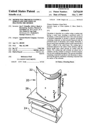
  • 4. 5,674,610 1 METHOD FOR CHROMUM COATING A SURFACE AND TAPE USEFUL IN PRACT CING THE METHOD BACKGROUNDOFTHEINVENTION This invention relates to the coating of the surface of a metallic substrate, and, more particularly, tothe application of a chromium coating to the surface. Inanaircraftgasturbine(jet) engine,airis drawn intothe front of the engine, compressed by a shaft-mounted compressor,andmixedwithfuel.Themixtureisburned,and the hot exhaust gases are passed through a turbine mounted on the same shaft. In the turbine, the flow of gases is deflected by sets ofturbine vanes to impinge upon a series of turbine blades mounted to turbine wheels supported on the shaft. The flow ofgas turns the turbine, which turns the shaftandprovidespowerto the compressor.The hotexhaust gases flow from the back ofthe engine, driving it and the aircraft forwardly. The hotter the exhaust gases, the more efficient is the operation ofthejetengine.Thereisthus an incentiveto raise the exhaust combustion gas temperature. The maximum temperature ofthe combustion gases is normally limitedby the materials used tofabricatetheturbine blades and turbine vanes of the turbine, upon which the combustion gases directlyimpingewhenthey areattheirhottesttemperatures. In currentpractice, the turbine blades and turbine vanes are made of nickel-base or cobalt-base superalloys. The superalloys are selected and processed to be strong, creep resistant, and fatigue resistant. However, the superalloys themselves arenothighlyresistanttoprogressivedamageby oxidation, hot corrosion, and erosion when exposed to the flowing hot combustion gases. These damage mechanisms normally establish the maximum operating lives of the turbine blades and turbine vanes. To extend the operating lives, the turbine blades and turbine vanes are coated with various types of coatings that protect them from oxidation, corrosion, and erosion. The turbine blades and vanes are arranged in stages according to the pressure and temperature of the exhaust gases that impinge upon them. Different coatings are used for the components of the various stages. In the high pressure stages, thermal barrier coating systems or aluminum-containing coatings are employed. In the low pressure stages, chromium coatings are favored. The coatings are applied during the fabrication of the turbine components.Thecoatings degrade duringservice as a result ofcontinued exposure to the hot exhaust gases and temperature changes during the operating cycles of the engine. The coatings can also be damaged during handling in the course ofmanufacturing, installation, and inspection. In all ofthese circumstances, repair ofthe coatings maybe required. Various techniques have been proposed to repair the chromium coatings of the low-pressure turbine blades and 5 10 15 25 30 35 45 55 turbine vanes.These repair techniques include,for example, . overchromiding by applying a new chromium coating over the entire old coating, applying chromium metal in a slurry or tape followed by sintering, and brush plating. Only the overchromidingprocesshas metwithanydegree ofsuccess. This approach is operable, but generally must be accom plished by returning the component to the original manufacturer, which can be inconvenient and costly. There is a need for a better approach to applying a chromium coating to a metallic surface, particularly under 65 2 field-repair conditions. Suchanapproach wouldbe ofvalue fortherepairofaircraftturbine components, butwouldalso be useful in a variety of other situations where chromium coatings are used. The present invention fulfills this need, and further provides related advantages. SUMMARY OF THE INVENTION This invention provides a method for applying a chro mium coatingto the surface ofa substrate.The coating can be deposited locally, making the approach ideal for the repair of damaged components. The deposition procedure requires only a furnace and does not require complex coating equipment.The coating can therefore be appliedin field repairs without returning the component to its manu facturer. The invention also provides a convenient and economical coatingtape that is used in the coatingprocess. Asusedherein,a"chromiumcoating”,sometimes termed a "chromide coating” in the art, is a coatingwhich contains chromium and thatis applied to the surface ofthe substrate inexcess ofany amountthatmaybepresentinthesubstrate alloy. During service,the chromium coatingis typically not purechromium,butincludesa concentrationofthe elements presentinthe substrateasaresultoftheinterdiffusion ofthe coatingand the substrate. Even wherethe chromium coating asinitially applied is substantially pure chromium, interdif fusion with the substrate typically occurs rapidly as a result of exposure at elevated temperatures. Such interdiffusion during application ofthe coating or thereafter during a heat treatment or service is acceptable and desirable to increase adherence of the coating to the substrate. In accordance with the invention, a method ofdepositing chromium ona surfaceofa metallic substrate comprisesthe stepsofprovidingametallicsubstratehavinga surface,and supplying a solid source of chromium and a solid reactant that is operable to react with solid chromium at elevated temperature to produce a gaseous chromium-containing compound. The method further includes heating the solid source of chromium and the solid reactant to elevated temperature to produce the gaseous chromium-containing compound, and contacting the gaseous chromium containing compoundtothe surface ofthe substrate,where upon chromium is deposited from the gaseous chromium containingcompoundontothe surfaceofthe substrate. Care istakentoremoveandpreventthe re-formationoftenacious, adherentsurface oxides on the substrate thatwould interfere with the deposition ofthe chromium coating. Theinventionispreferablypracticed usingacoatingtape to supply the reactants in a convenient form and a closed reactor to prevent the escape of the chromium-containing gas. In accordance with this aspect of the invention, a method of depositing chromium on a surface of a metallic substrate comprises the steps of providing a metallic sub strate having a surface and supplying a coating tape. The coatingtape comprises a source layerincludingapowdered source ofchromium, a solid reactantthatis operableto react with solid chromium at elevated temperature to produce a gaseous chromium-containing compound, an inert powder dispersed with the powdered source of chromium, and a binder. The method further includes positioning the coating tape adjacent to the surface of the substrate, placing the coating tape and substrate into a container and sealing the container, and heating the coating tape and the substrate to elevated temperaturewithinthesealed container.Again,care is taken to avoid surface oxides on the substrate that could interfere with the chromium deposition. The coatingtape can further include aporous media layer of a porous media material affixed to the source layer. The
  • 5. 5,674,610 3 porous media layer physically separates the source layer from the substrate. Solid reactant material from the source layer is prevented from contacting and possibly reacting with the substrate, and the inert powder in the source layer cannotbecome embeddedintothe substrate asthe chromium is deposited. Chromium-bearing gas from the source layer passesthroughtheporousmedialayertoreachthesubstrate. The porous media material is typically a mixture ofan inert powdered material and a binder. When it is used, the two-layertape structure is positioned with theporous media layer in contact with the substrate. The present invention also extends to the coating tape, including both the one-layer embodiment having only the source layer and the two-layer embodiment having the source layer and the porous media layer. The source layer is preferably formed of a mixture of powdered chromium, a solid halide such as ammonium fluoride or ammonium chloride as the Solid reactant (also sometimes termed an "activator”), an Oxide powder such as chromium oxide powder mixed with the powdered chro miumtopreventitfrom agglomeratingandsintoting,andan organicbinder.Theporous media layer ispreferably formed of a mixture ofa metallic oxide such as aluminum oxide or chromium oxide and a binder, or a ceramic gauze. In each type of tape, the organic binder is present to bind the constituents together in the tape during manufacture, shipment, storage, and placement of the tape. The binder vaporizes or burns away as the tape is heated. The use of the coating tape that produces a gaseous chromium-containingcompoundinthepreferredapplication process is a particularly convenient approach to depositing the chromium onto the surface of the substrate. It is not necessary to apply a chromium vapor overpressure to the entire partbeingchromided.The chromiumin thetape is not melted, so that there is no risk ofthe unintentional deposi tion of chromium masses on the substrate which would adversely affect its airfoil performance. The approach requires only that the tape be applied to the surface of the substrate, the substrate and applied tape be placed into a container, and the substrate and applied tape be heated to a temperature sufficient that the reaction and deposition can OCC. Other features and advantages of the present invention will be apparent from the following more detailed descrip tion ofthe preferred embodiment, taken in conjunction with the accompanying drawings, which illustrate, by way of example, the principles of the invention. BRIEF DESCRIPTION OF THE DRAWINGS FIG. 1 is a perspective view ofa gas turbine component; FIG. 2 is a sectional view through the component of FIG. 1, taken generally along line 2-2, illustrating a chromium coating on the surface ofthe component; FIG. 5 is a block diagram of one embodiment of the approach of the invention; FIG. 4 is an elevational view ofa one-layer coating tape; FIG. 5 is an elevational view of atwo-layer coating tape; FIG. 6 is a schematic sectional view illustrating one embodiment of the application of the coating tape to the surface of the component; and FIG. 7 is a schematic sectional view illustrating a second embodiment of the application of the coating tape to the surface ofthe component. DETALED DESCRIPTION OF THE PREFERRED EMBODMENTS FIG. 1 depicts a componentofa gas turbine engine such asaturbineblade orturbinevane,andinthis caseis depicted 5 10 15 25 30 35 45 50 55 60 65 4 asaturbine blade20.Theturbineblade 20 includes an airfoil 22 againstwhich the flow ofhotexhaustgas is directed.The turbine blade 20is mountedtoaturbine disk(not shown) by a dovetail 24which extends downwardly from theairfoil 22 and engages a sloton theturbine disk.Aplatform26extends longitudinally outwardly from the area where the airfoil 22 is joined to the dovetail 24. A number of cooling channels desirably extendthrough the interioroftheairfoil22, ending in openings 28 in the surface of the airfoil 22. A flew of cooling air is directed through the cooling channels, to reduce the temperature of the airfoil 22. FIG. 2 illustrates in a section through the airfoil 22 a chromium coating 30 deposited upon a surface 31 of the turbine blade 20, which thereby acts as a substrate 32. The substrate 32 may beformed of any operable material, but a preferred base metal from which the substrate 32 is formed is a nickel-base superalloy such as Rene 77, Rene 80, or Rene 108. The preferred superalloy substrate is Rene 77. which has a nominal composition, in weight percent, of 15 percent cobalt, 14.2 percent chromium, 4.3 percent aluminum, 3.4 percent titanium, 4.2 percent molybdenum, balance nickel and trace elements. The chromium coating 30, as initially deposited upon the substrate 32, is typically continuous with a thickness of about 0.0005 to about0.0015 inches, nominally about0.001 inches. However,the continuous coating may be interrupted at aflaw 34, where the coating 30 is partially or completely (asillustrated) removedfrom the surface 31 ofthe substrate 32. Where present, the chromium coating 30 protects the substrate 32 from damage by oxidation, hot corrosion, and erosionby thehotexhaustgas.Where the chromiumcoating 30 is removed at a flaw 34, the hot exhaust gas can contact the unprotected substrate32and quickly damageitbythese mechanisms. Flaws 34 occasionally occur due to damage during manufacturing, handling, installation, or service. Flaws can be detected duringinspections.The preferred application of the present invention is to repair such flaws 34. The inven tionwill be described in relation tothe use ofa coatingtape to make the repair, because such a tape is convenient for field repairs. Amethod forpracticing the invention is depicted in FIG. 3. A metallic substrate 32 is provided, numeral 40. The metallic substrate may be a turbine blade or turbine vane, another gas turbine component, or other article. The only limitation on the choice ofthe metallic substrate is that it be suitable for the application of a chromium coating. The surface of the substrate is cleaned of organic residue and oxidesby conventional cleaningtechniques.Thepresence of tenacious oxides on the surface of the substrate interferes with the subsequent chromium deposition. A coating tape 60 is supplied, numeral 42. Two embodi ments ofthe coating tape 60 are illustrated in FIGS. 4 and 5. In a one-layer coating tape embodiment of FIG. 4, there is a single source layer 62. In a two-layer coating tape embodiment of FIG. 5, there is a source layer 62 and a porous media layer 64. Additionally, there may be adhesive layers as needed andwhich willbe described subsequently. (The adhesive layers are not counted in the terminology “one-layer" and “two-layer”, inasmuch as the presence and type of the adhesive layers can be varied for different applications.) The source layer 62 is a mixture of a solid powdered source ofchromium,a solid reactantthatis operableto react with solid chromium at elevated temperature to produce a gaseous chromium-containing compound, an inert powder
  • 6. 5,674,610 5 dispersed with thesolidpowdered source of chromium,and abinder.Preferably,thesolidpowderedsourceofchromium is chromiumpowder,typically-100mesh,high-puritychro mium powder. Preferably,the solidreactant (also termed an “activator") is a solid halide compound, such as ammonium fluoride or ammoniumchloride.Preferably,theinertpowderisanoxide powder such as chromium oxide powder, typically of a size of -400 mesh. The inert powder serves to prevent the chromium powderfrom sintering and densifying duringthe subsequent heating step, which would prevent the chromium-containing gas from reaching the substrate. Preferably,thebinderis anorganicbindersuchasanacrylic S. Even more preferably, the source layer 62 is prepared by mixing from about 60 to about 90 parts by weight of chromium powder and from about 5 to about 39 parts by weight of chromium oxide powder, and then adding to this mixture from about 1 to about 5 parts by weight ofammo nium fluoride or ammonium chloride. Most preferably, the Source layer 62 includes about 89 parts by weight of chromium powder, about 10 parts by weight of chromium oxide powder, and about 1 part by weight of ammonium fluoride,withwhich the binderis mixed.Typically,about85 parts by weight ofthis mixture is mixedwith up to about 15 parts by weight of the binder, to form a mixture with a suitable consistency for forming the source layer. Theporous media layer64, usedinthetwo-layer embodi ment of FIG. 5, is made ofan inert material through which the chromium-containing gas passes but does not deposit upon. Theporous media layer 64 can bea ceramicgauze or the like.Theporous medialayer64 canalsobea mixtureof a ceramic powder, such as aluminum oxide or chromium oxide,andabinder. In thelattercase,theporous medialayer 64 is a mixture ofabout 85 parts by weight ofthe ceramic powder and about 15 parts by weight ofan organic binder such as an acrylic resin. The source layer 62 and the porous media layer 64 are separately manufactured by known processes for the fabri cation of such layers. In each case, the constituents are mixedtogetherandformedintoa layerby extrusion, rolling, a doctorblade, orthe like.The source layer 62is preferably fromabout0.010toabout0.015inches thick,and theporous media layer 64ispreferablyfromabout0.015 toabout0.025 inches thick, as fabricated. In a working embodiment, the source layer 62 was 0.013 inches thick And the porous media layer64was 0.020inches thick.Alternatively,forthe two-layercoatingtape 60 ofFIG. 5,the source layer 62and the porous media layer 64 can be individually mixed, and thereafter co-extruded, co-rolled, or the like to produce the two-layered tape. Afirst adhesive layer 66 is preferably provided to fix the coatingtape 60to thesubstrate32. Inthe one-layerembodi ment ofFIG. 4,thefirstadhesive layer66isprovidedon one side ofthe source layer 62. In the two-layer embodiment of FIG. 5,thefirstadhesive layer 66 is provided on one side of the porous media layer 64, the side which does not lie in facing contact to the source layer 62. The adhesive used in the first adhesive layer 66 is one thatwill hold the coating tape 60 tothe substrate32 duringheating,butthereafter will vaporize or burn away at elevated temperature. The pre ferred adhesive in the first adhesive layer 66 is a pressure sensitive adhesive provided as a solution ofphenolic resin and nitro rubber in a solvent. In some cases, the first adhesive layer 66 may be omitted ifthe coating tape 60 is held in place against the substrate 32 by some other technique, such as an applied pressure. 15 20 25 30 35 40 45 50 55 65 6 A second adhesive layer 68 may be present between the Source layer 62 And the porous media layer 64 in the two-layer embodimentofFIG.5. (Nosecondadhesive layer 68 is used with the one-layer embodiment ofFIG. 4.)The second adhesive layer 68 may also not be needed for the two-layer embodiment, where the source layer 62 and the porous media layer 64 are held together by some other technique, as by their mechanical interlockingproduced by a co-production process such as co-extrusion. Where present, the second adhesivelayer 68is made ofan adhesive thatwill hold the source layer 62 totheporous media layer 64 duringhandling, storage,and heating,butthereafterwill vaporize or burn away at elevated temperature. The pre ferred adhesive in the second adhesive layer 68 is the same as the adhesive of the first adhesive layer Returning to the method illustrated in FIG. 3,the coating tape 60 is positioned adjacent to the substrate, numeral 44. The coating tape is typically provided with a paper backing on the first adhesive layer 66 to protectit during handling. The paper backing is first peeled away, and the coating is applied to the substrate 32. FIGS. 6 and 7 illustrate the positioning of the two-layer coatingtape and the one-layer coating tape, respectively, in contactwith the substrate32. In each case,thefirstadhesive layer 66 is placedinto contactwith the substrate 32. Forthe two-layer coating tape of FIG. 6, the coating tape 60 is Oriented such that the porous media layer 64 is between the substrate 32 and the source layer 62.The coating tape 60 is normally applied overaflaw.Oneadvantage ofthe use ofthe coating tape is that it may be cut to size to fit the flaw. Another advantage is that the coating tape may be bent to conform to curved or irregular surfaces (although the sur faces of FIGS. 6 and 7 are illustrated as flat). The coating tape 60 and substrate 32 are placed into a container70, in thepreferred embodiment.The container70 includes a bottom 72 and a top 74. The substrate 32 with attached coating tape 60 is placed into the bottom 72. The top74is placed into position and closed. Preferably,the top 74 is not sealed to the bottom 72, as a loosely closed container has been found sufficient as long as a proper atmosphere is maintained around the container 70. Alternatively, the container 70 could be sealed, as with a weld 76 of the top to the bottom. The container 70 is preferably made ofa metalsuchas Inconel 625, Inconel 601, or stainless steel, andthe seal 76, where used, is preferably a Weld. The container 70 preferably is sized so that the substrate 32 fits therein with as Small a clearance as reasonably possible. One important function of the container 70 is to prevent the escape of chromium-containing gas from the location where the chromium layer is to be deposited, and for this reason there is as little excess space within the container as possible. Any excess space within the container may optionally be, and preferably is,filled with a substance upon which the chromium will not readily deposit, such as aluminum oxide or chromium oxide powder. Such a filler also aids in holding the coating tape 60 in contact with the surface of the substrate. It is important that the portion of the surface of the Substrate upon which the chromium is to be deposited not have an oxide layer that could interfere with the deposition. As notedearlier, anypre-existingtenacious oxideis cleaned fromthe surfacepriorto contactingthe coatingtape 60tothe surface. To prevent formation of any further oxide during heatingand chromium deposition, the entire container, with the enclosed substrate and coating tape, is surrounded with
  • 7. 5,674,610 7 a non-oxidizing atmosphere (Alternatively, ifthe container is sealed,theinteriorofthecontainerwouldinitiallybefilled with the non-oxidizing atmosphere.) The atmosphere is desirably hydrogen or argon gas, or a mixture thereof. A positive pressure ofthe non-Oxidizing gas is normally main tained to prevent leakage of oxygen into the container. An alternative approach also within the scope oftheterm "place the coating tape and substrate into a container” is illustrated in FIG. 7. Here, a barrier cover 78 is placed over thecoatingtape60anda smallportion ofthe adjacentregion ofthe substrate32.Thebarriercover78has substantiallythe same functions as the container 70: specifically preventing the chromium-containinggas from escaping, forcingthe gas tocontactthe substrate32inthe desiredarea,and excluding oxygen from the region upon which the chromium is to be deposited. The barrier cover 78 is preferably made of a ceramic such as non-porous aluminum oxide, and is atleast about 0.010 inches thick. Anon-oxidizingpurge gas such as hydrogen or argon is passed over the exterior ofthe barrier cover to exclude oxygen. FIG. 6 illustrates the two-layer coating tape in conjunc tion with the container, while FIG. 7 illustrates theone-layer coating tape in conjunction with the barrier cover. These arrangements are intended to depict possible combinations, but the invention is not so limited. For example, the one layer coating tape can be used in conjunction with the container, and the two-layer coating tape can be used in conjunction with the barrier cover. The coating tape and substrate are heated to a reaction temperature, numeral48.Apreferredreaction temperatureis 2000 F. At this temperature, the solid reactant reacts with the source of chromium to produce a chromium-containing gas. In the most preferred case, Ammonium fluoride reacts with chromium powder to produce chromium fluoride gas. The chromium-containing gas diffuses to the substrate 32 (through the porous media layer 64in the two-layer coating tape). When the chromium-containing gas contacts the sub strate 32, it decomposes to deposit high-purity chromium thereon. The process continues until a desired thickness of deposited chromium is produced. The approach of the invention has been practiced using the two-layer coating tape and container embodimentillus trated in FIG. 6 (except that the container was not sealed) and the method of FIG. 3. Atwo-layer coating tape 60 was prepared using the most preferred embodiment discussed previously. The coating tape 50 was applied to a Rene 77 substrate, placed into the container, and heated to 2000 F. for 8 hours in a hydrogen atmosphere. After cooling, the remnant of the tape was removed and the coating was inspected and analyzed. The coating was about 0.001 inch thick. Thecoatingwas predominantly chromium at its upper surface, with a relatively small concentration oftheelements originally present in the substrate. At increasing depths within the coating, the coating contained an increasing amount ofthe elementsfound in the substrate.Thepresence of the substrate elements is expected as a result ofinterdif fusion of the chromium and the substrate, and such inter diffusion is both acceptable and desirable to ensure adher ence of the coating to the substrate. This invention has been described in connection with specific embodimentsand examples. However,those skilled in the artwill recognize various modificationsandvariations ofwhich the present invention is capable without departing from its scope as represented by the appended claims. What is claimed is: 1. Acoating tape useful in applying a chromium coating to a surface of a substrate, comprising: O 15 25 30 35 45 SO 55 65 8 a source layer including apowdered source ofchromium, a solid reactant that is operable to react with solid chromiumat elevatedtemperaturetoproduceagaseous chromium-containing compound, an inert powder dis persed with the powdered source of chromium, the inert powder comprising chromium oxidepowder, and a source layer binder; and a porous medialayerincludinganinertpowdered ceramic anda binder,the porous media layerhaving afirstside affixed to the source layer to form the coating tape. 2. The coating tape of claim 1, wherein the source layer comprises from about 60 to about 90 parts by weight of chromium powderasthe source ofchromium, from about 1 to about 5parts byweight ofahalide compound as the solid reactant,fromabout5toabout39partsbyweightofaninert oxide powder, and a polymeric layer binder. 3. The coating tape of claim 1, further including an adhesive on a second side of the porous media layer. 4. The coating tape of claim 1, wherein the source layer binder is an acrylic resin. 5. A coating tape useful in applying a chromium coating to a surface of a substrate comprising: a sourcelayercomprisinga powered source ofchromium, a solid reactant that is operable to react with solid chromium at elevatedtemperaturetoproduceagaseous chromium-containing compound, and an inert powder dispersed with the powered source of chromium; and a ceramicporous media layerhavingafirst side affixed to the source layer. 6. The coating tape ofclaim 5, wherein the source layer comprises from about 60 to about 90 parts by weight of chromium powderasthe source ofchromium, from about 1 toabout5partsbyweightofahalide compoundasthe solid reactant, andfrom about 5 to about39 parts by weight ofan inert oxide powder. 7.Thecoating oftapeofclaim5wherein the sourcelayer comprises about 89 parts by weight of chromium powder, about 1 part by weight ofammoniumfluoride, and about 10 parts by weight of chromium oxide powder. 8. The coating tape of claim 5, further including an adhesive on a second side of the porous media layer. 9. The coating tape of claim 8, wherein the adhesive comprises phenolic resin and nitro rubber. 10.The coatingtape ofclaim.5,wherein the solid reactant is a halide compound. 11. The coating tape of claim 10, wherein the halide compound is selectedfrom the group consisting of ammo nium chromide and ammonium fluoride. 12. The coating tape ofclaim 5, wherein the source layer further includes a source layer polymeric binder. 13. The coating tape of claim 5, wherein the source layer polymeric binder is an acrylic. 14. The coating tape of claim 5, wherein the ceramic porous media layer comprises a ceramic gauze. 15. The coating tape of claim 5, wherein the ceramic porous media layer comprises a mixture of a ceramic media powder and an organic porous media layer binder. 16. The coating tape of claim 5, wherein the ceramic porous media layer comprises a mixture ofabout85 parts by weight ofa ceramic media powder and about 15 parts by weight of an organic porous media layer binder. k : :