SlideShare a Scribd company logo
1 of 6
Download to read offline
USOO5975852A
United States Patent (19) 11 Patent Number: 5,975,852
Nagaraj et al. (45) Date of Patent: Nov. 2, 1999
54) THERMAL BARRIER COATING SYSTEM 5,498,484 3/1996 Duderstadt .............................. 428/633
AND METHOD THEREFOR 5,512,382 4/1996 Strangman . ... 428/672
5,514,482 5/1996 Strangman .............................. 428/623
75 Inventors: BanaloreA. Nagaraj, West Chester; E. i.1. SA et al. .. it is2- Y-12 IanSmall ..............................
St. Most MyA. 5,667,663 9/1997 Rickerby et al. ....................... 205/170
9, s 5,716,720 2/1998 Murphy ................................... 428/623
5,759,640 6/1998 Mannava et al. ....................... 427/554
73 Assignee: General Electric Company, Cincinnati,
Ohio
21 Appl. No.: 08/829,296
22 Filed: Mar. 31, 1997
(51) Int. Cl." ...................................................... B32B 15/04
52 U.S. Cl. .................................. 416/241 R; 415/200 R;
416/241 B; 428/141; 428/156; 428/472;
428/701; 428/702; 428/615; 428/623; 428/632;
428/650; 428/552; 428/669; 428/680; 428/652;
428/668; 427/348; 427/402; 427/419.1;
427/419.2
58 Field of Search ............................ 416/241 B, 241 R;
428/633, 614, 623, 472, 469, 615, 141,
156, 701, 702, 632, 650, 552, 669, 680,
652, 668; 415/200 R; 427/348, 402,419.1,
419.2, 419.3
56) References Cited
U.S. PATENT DOCUMENTS
4,399,199 8/1983 McGill et al. .......................... 428/633
5,116,691 5/1992 Darolia et al. ....... ... 428/614
5,238,752 8/1993 Duderstadt et al. ..... ... 416/241 B
5,302.465 4/1994 Miller et al. ......... ... 428/552
5,407,705 4/1995 Vakil ................ ... 427/255
5,427.866 6/1995 Nagaraj et al. ......................... 428/610
Primary Examiner Archene Turner
Attorney, Agent, or Firm Andrew C. Hess; David L.
Narciso
57 ABSTRACT
A thermal barrier coating and a method for forming the
coating on an article designed for use in a hostile thermal
environment, Such as turbine, combustor and augmentor
components of a gas turbine engine. The method is particu
larly directed to increasing the Spallation resistance of a
thermal barrier coating System that includes a thermal insu
lating ceramic layer. The coating System of this invention
generally includes a nickel aluminide alloy on which an
aluminum oxide layer is formed, over which a ceramic layer
is depositedSo as to overlie and contact the aluminum oxide
layer. The coating System does not include a bond coat, Such
as a diffusion aluminide or MCrATY coating known in the
prior art. The nickel aluminide alloy may be a binary NiAl
alloy consisting essentially of nickel and aluminum in
Stoichiometric amounts, or may contain one or more
oxygen-active elements. The NiAl alloy may be provided as
a monolithic layer on a Superalloy, or may be the base
material for the article on which the thermal barrier coating
is formed.
20 Claims, 1 Drawing Sheet
Nov. 2, 1999 5,975,852U.S. Patent
1FG.
FG. 2
5,975,852
1
THERMAL BARRIER COATING SYSTEM
AND METHOD THEREFOR
This invention relates to thermal barrier coating Systems
for components exposed to high temperatures, Such as the
hostile thermal environment of a gas turbine engine. More
particularly, this invention is directed to a thermal barrier
coating System that comprises a thermal insulating ceramic
layer deposited directly on a nickel aluminide Substrate,
particularly a single-crystal nickel aluminide, and therefore
without an adhesion-promoting bond coat.
BACKGROUND OF THE INVENTION
Higher operating temperatures for gas turbine engines are
continuously Sought in order to increase their efficiency.
However, as operating temperatures increase, the high tem
perature durability of the components of the engine must
correspondingly increase. Significant advances in high tem
perature capabilities have been achieved through formula
tion of nickel and cobalt-base Superalloys, though Such
alloys alone are often inadequate to form components
located in certain Sections of a gas turbine engine, Such as
the turbine, combustor and augmentor. A common Solution
is to thermally insulate Such components in order to mini
mize their Service temperatures. For this purpose, thermal
barrier coatings (TBC) formed on the exposed surfaces of
high temperature components have found wide use.
To be effective, thermal barrier coatings must have low
thermal conductivity, Strongly adhere to the article, and
remain adherent throughout many heating and cooling
cycles. The latter requirement is particularly demandingdue
to the different coefficients of thermal expansion between
materials having low thermal conductivity and Superalloy
materials typically used to form turbine engine components.
Thermal barrier coating Systems capable of Satisfying the
above requirements have generally required a metallic bond
coat deposited on the component Surface, followed by an
adherent ceramic layer that Serves to thermally insulate the
component. In order to promote the adhesion ofthe ceramic
layer to the component and inhibit oxidation of the under
lying Superalloy, the bond coat is typically formed from an
oxidation-resistant aluminum-based intermetallic Such as a
diffusion aluminide or platinum aluminide, or by an
oxidation-resistant aluminum-containing alloy Such as
MCrATY (where M is iron, cobalt and/or nickel).
Various ceramic materials have been employed as the
ceramic layer, particularly Zirconia (ZrO2) stabilized by
yttria (YO), magnesia (MgO) or other oxides. These
particular materials are widely employed in the art because
they can be readily deposited by plasma Spray, flame Spray
and electron beam vapor deposition (EBPVD) techniques,
have low coefficients of thermal expansion, and when pro
cessed properly show good adhesion to Substrate materials.
In order to increase the resistance of the ceramic layer to
Spallation when Subjected to thermal cycling, the prior art
has proposed various improved coating Systems, with con
siderable emphasis on ceramic layer microStructures having
enhanced Strain tolerance as a result of the presence of
porosity, microcracks andSegmentation ofthe ceramic layer.
Thermal barrier coating Systems employed in higher tem
perature regions ofa gas turbine engine are typically depos
ited by physical vapor deposition (PVD) techniques that
yield a grain Structure that is able to expand without causing
damaging stresses that lead to Spallation.
The bond coat is also critical to promoting the Spallation
resistance of a thermal barrier coating System. AS noted
15
25
35
40
45
50
55
60
65
2
above, bond coats provide an oxidation barrier for the
underlying Superalloy Substrate. Conventional bond coat
materials contain aluminum, Such as the diffusion alu
minides and MCrATY alloys noted above, which enables
Such bond coats to oxidize and grow a Strong adherent
continuous aluminum oxide layer (alumina Scale). The alu
minum oxide layer chemically bonds the ceramic layer to
the bond coat, andprotects the bond coat from Oxidation and
hot corrosion. Though bond coat materials are particularly
alloyed tobe oxidation-resistant, oxidation inherently occurs
overtime atelevated temperatures, which gradually depletes
aluminum from the bond coat. In addition, aluminum is lost
from the bond coat as a result of interdiffusion into the
Superalloy Substrate. Eventually, the level of aluminum
within the bond coat is sufficiently depleted to prevent
further growth ofoxide, at which time Spallation may occur
at the interface between the bond coat and the aluminum
oxide layer or the interface between the oxide layer and the
ceramic layer.
In addition to depletion of aluminum, the ability of the
bond coat to form the desired aluminum oxide layer can be
hampered by the diffusion of elements from the Superalloy
into the bond coat, Such as during formation of a diffusion
aluminide coating or during high temperature exposure.
Oxidation ofSuch elements within the bond coat can become
thermodynamically favored as the aluminum within the
bond coat is depleted through oxidation and interdiffusion.
Elements Such as nickel, chromium, titanium, tantalum,
tungsten, molybdenum and hafnium can increase the growth
rate of aluminum oxide and form Voluminous, nonadherent
Scales that may be deleterious to adhesion of the ceramic
layer.
From the above, it is apparent that the service life of a
thermal barrier coating is dependent on the bond coat used
to anchor the thermal insulating ceramic layer. Once Spal
lation ofthe ceramic layerhas occurred, the component must
be refurbished or Scrapped at considerable cost. Therefore,
it would be desirable iffurther improvements were possible
for the Service life of a thermal barrier coating System.
SUMMARY OF THE INVENTION
It is an object of this invention to provide a novel thermal
barrier coatingSystem and a method for forming the coating
System on an article designed for use in a hostile thermal
environment.
It is another object of this invention that the coating
System does not include a bond coat.
It is yet another object of this invention that the coating
System entails the formation ofa thermal insulatingceramic
layer on a Surface formed by a beta-phase nickel aluminide
alloy.
It is a further object of this invention that the nickel
aluminide alloy forms the article or a layer on the article.
The presentinvention generally providesa thermalbarrier
coatingSystem and a method for forming the coatingSystem
on an article designed for use in a hostile thermal
environment, Such as turbine, combustor and augmentor
components of a gas turbine engine. The method is particu
larly directed to increasing the Spallation resistance of a
thermal barrier coating System that includes a thermal insu
lating ceramic layer.
The thermal barrier coating System of this invention
generally includesa nickelaluminide alloy ofpredominantly
the beta (B) NiAl phase and on which an aluminum oxide
layer is formed, over which a ceramic layer is deposited So
as to overlie andcontact the aluminum oxide layer. Notably,
5,975,852
3
the coating System does not include a bond coat, Such as
diffusion aluminide and MCrATY coatings known in the
prior art. According to the invention, the nickel aluminide
alloy may be a binary NiAl alloy consisting essentially of
nickel and aluminum in Stoichiometric amounts, or may
contain an oxygen-active element, Such as yttrium, cerium,
Zirconium or hafnium, to Strengthen the NiAl alloy. Also
according to this invention, a component on which the
thermal barriercoating is formed may be formed entirely by
the nickel aluminide alloy, Such as a single-crystal invest
ment casting. Alternatively, the component may be formed
by a Superalloy on which the nickel aluminide alloy is
provided as a monolithic Surface layer.
The processing Steps of the invention generally include
providing a component whose Surface is formed by the
nickel aluminide alloy, forming an aluminum oxide layer on
the nickel aluminide alloy, and then depositing a ceramic
layer on the oxide layer. Prior to developing the oxide layer,
the Surface ofthe nickel aluminide alloy ispreferably treated
to have a Surface finish of not greater than about 25
microinches (about 0.6 micrometer) R, Such as by
electropolishing, vapor honing, polishing or light abrasive
blasting.
According to this invention, a thermal barrier coating
System is capable of exhibiting enhanced Service life and
Spallation resistance when a nickel aluminide alloy Serves as
the Substrate on which an aluminum oxide layer is grown
and on which a ceramic layer is deposited. Notably, this
invention completely omits a traditional aluminum-based
bond coat, instead using a Substantially monolithic NiAl
intermetallic from which the component is formed or which
forms a thick layer on the component. A Substantially
monolithic layer of NiAl may be formed on a component
using a process Such as,but not limited to, diffusion bonding
an NiAl foil, plasma Spraying, physical vapor deposition or
Sputtering. AS Such, the invention completely avoids inter
actions that typically occur between bond coats and a
Superalloy Substrate on which Such bond coats are formed.
In addition, NiAl intermetallic alloys provide a large reser
voir for formation ofthe desired aluminum oxide Scale, and
are free of elements that might otherwise form Voluminous
nonadherent oxides that would otherwise promote Spalla
tion. The result is a thermal barrier coating System whose
thermal cycle life has been Surprisingly found to be up to
about ten times greater than conventional coating Systems.
Finally, elimination of the bond coat also yields significant
Savings in manufacturing cost and time.
Other objects and advantages of this invention will be
better appreciated from the following detailed description.
BRIEF DESCRIPTION OF THE DRAWINGS
The present invention will now be described, by way of
example, with reference to the accompanying drawings, in
which:
FIG. 1 is a perspective view of a high pressure turbine
blade; and
FIG. 2 is a cross-sectional view of the blade of FIG. 1
along line 2-2, and shows a thermal barrier coating on the
blade in accordance with this invention.
DETAILED DESCRIPTION OF THE
INVENTION
The present invention is generally applicable to compo
nents that operate within environments characterized by
relatively high temperatures, and are therefore Subjected to
15
25
35
40
45
50
55
60
65
4
Severe thermal Stresses and thermal cycling. Notable
examples of Such components include the high and low
preSSure turbine nozzles and blades, Shrouds, combustor
liners and augmentor hardware of gas turbine engines. One
such example is the high pressure turbine blade 10 shown in
FIG.1. The blade 10 generally includes an airfoil 12 against
which hotcombustion gases are directed during operation of
the gas turbine engine, and whose Surface is therefore
Subjected to Severe attack by Oxidation, corrosion and ero
sion.The airfoil 12isanchoredto a turbine disk(notshown)
with a dovetail 14 formed on a root section 16 of the blade
10. Cooling passages 18 are present in the airfoil 12 through
which bleed air is forced to transfer heat from the blade 10.
While the advantages of this invention will be described
with reference to the high pressure-turbine blade 10 shown
in FIG. 1, the teachings of this invention are generally
applicable to any component on which an environmental or
thermal barrier coating System may be used to protect the
component from its environment.
Represented in FIG. 2 is a thermal barrier coating System
20 in accordance with this invention. AS Shown, the coating
system 20 includes a ceramic layer 26 bonded to a substrate
22 with an aluminum oxide layer 24. According to the
invention, the Substrate 22 is a nickel aluminide alloy of
predominantly the beta NiAl phase, and may be in the form
of a single-crystal casting that forms the entire blade 10.
Alternatively, the Substrate 22 can be limited to a layer on
the Surface of the blade 10, which can be formed of a
Suitable high-temperature material, Such as a nickel or
cobalt-base Superalloy. In this embodiment ofthe invention,
the NiAl Substrate 22 can be formed using a suitable
deposition process, including low pressure plasma Spraying
(LPPS), diffusion bonding, sputtering and electron beam
evaporation. A minimal thickness for an NiAl layer is about
125 micrometers in order to provide an adequate Supply of
aluminum for oxide formation, as will be discussed below.
Anovel feature of this invention is that the thermalbarrier
coating system 20 is formed directly on the NiAl Substrate
22 without a bond coat, Such as the diffusion aluminide and
MCrATY alloys conventionally required in the prior art. As
Such, the Substrate 22 is not prone to interactions and
interdiffusion ofelements observed with prior artbondcoats
and their Superalloy Substrates. An optional noble metal
layer between the NiAl Substrate 22 and the ceramic layer
26,with a thickness ofabout4 to about 10 micrometers, may
be included to promote formation of desirable oxides and
thereby improve the environmental resistance of the Sub
strate 22. This layer would not be deemed a bond coat in
accordance with the accepted definition in the art, because
Such a thin layer of noble metal (e.g., platinum, rhodium,
palladium) would quickly diffuse into the substrate 22
during high temperature processing and Service.
To attain a Strain-tolerant columnar grain Structure, the
ceramic layer 26 is preferably deposited by physical vapor
deposition using techniques known in the art. A preferred
material for the ceramic layer 26 is an yttria-Stabilized
Zirconia (YSZ), a preferred composition being about 6 to
about 8 weight percent yttria, though other ceramic mate
rials could be used, Such as yttria, nonstabilized Zirconia, or
Zirconia Stabilized by ceria (CeO2) or Scandia (ScC)). The
ceramic layer26 is deposited to a thickness that is Sufficient
to provide the required thermalprotection for the underlying
substrate 22 and blade 10, generally on the order of about
125 to about 300 micrometers.
As with prior art bond coats, the surface of the NiAl
substrate 22 oxidizes to form the aluminum oxide layer 24
to which the ceramic layer 26 chemically bonds. AS a
5,975,852
S
monolithic NiAl alloy, as opposed to a Superalloy or diffu
Sion layer that may contain dispersions of aluminides, the
Substrate 22 provides a large reservoir from which the oxide
layer 24 is formed. The substrate 22 can be formed of the
binary NiAl intermetallic, or may be alloyed to contain
Selected elements Such as tantalum and hafnium to improve
the mechanical and/or physical properties of the Substrate
22. In addition,the NiAl alloy may be alloyed to contain one
or more oxygen-active elements, Such as yttrium, hafnium,
cerium, Zirconium and others, to promote adherence of the
aluminum oxide layer 24.
According to this invention, the NiAl Substrate 22 is
processed to provide a very Smooth, contaminant-free inter
face with the ceramic layer 26, which has been found to
unexpectedly promote Spallation resistance of the ceramic
layer 26. In particular, Superior results have been achieved
by processing the Surface of the Substrate 22 by
electropolishing, vapor honing, polishing or light grit blast
ing to yield a Surface finish of not more than about 25
microinches (about 0.6 micrometer) R. Such results are
unexpected in View of the traditional belief that a rough
interface, e.g., an R of at least 50 microinches, is required
to achieve acceptable resistance to Spallation with diffusion
aluminide bond coats.
During the evaluation of this invention, Single-crystal
NiAl alloy Specimens and a single-crystal nickel-base Super
alloy Specimen were provided with thermal barrier coating
Systems that included a thermal insulating ceramic layer of
yttria-stabilized zirconia (YSZ) deposited by physical vapor
deposition. The coating System for the Superalloy Specimen
was also conventionally formed to include a diffusion alu
minide bond coat whose Surface was grit blasted to attain a
conventionally-suitable surface roughness of about 50
microinches R. In contrast, ceramic layers for the NiAl
Specimens were deposited directly on the Surfaces of the
NiAl alloy, i.e., without a bond coat. During deposition of
the ceramic layers, an oxide layer of about 0.2 to about 0.5
micrometerwas developed. Three different NiAl alloys were
evaluated, and theirSurfaces were prepared for deposition of
the ceramic layerby either electropolishing or vapor honing
as indicated in Table I. Spallation resistance of the coating
Systems were evaluated by thermal cycling between room
temperature and about 2075° F (about 1135° C). All of the
NiAl alloys were the beta-phase NiAl intermetallic, with
specific compositions for the NiAl alloys indicated in Table
I in atomic percents.
TABLE I
SPECIMEN SURFACE PREPARATION CYCLES
Ni-base superalloy + Grit Blasted 391
Diffusion Aluminide
Ni-50A Electropolished 218O
N-SOA-O.1Y Electropolished 2040
Ni-49.8A-0.5HF Electropolished 6000
Ni-49.8A-0.5HF Vapor Honed 8OOO
“Cycles' denotes the number of cycles Survived without
Spallation of the thermal barrier coating. Testing of the
Ni-49.8Al-0.5Hf alloys was discontinued without spallation
having occurred.
From the above, it can be seen that the thermal barrier
coatings of the NiAl Specimens were considerably more
resistant to Spallation than the Ni-base Superalloy with a
conventional diffusion aluminide bond coat. These results
were unexpected, in that a large mismatch in coefficients of
thermalexpansion existsbetween that ofthe NiAl alloysand
15
25
35
40
45
50
55
60
65
6
the ceramic thermal barrier coating. The anisotropy of the
Single-crystal NiAl Specimens was also expected to reduce
the Spallation resistance of the thermal barrier coatings of
the NiAl Specimens. The above results were also unexpected
because the Surfaces of the NiAl alloys were prepared
contrary to industry practice, in that a Smoother Surface
yielded enhanced Spallation resistance. Both electropolish
ing and vapor honing produced a Smooth Surface (an R of
about 10 to about 25 microinches, about 0.25 to about 0.6
micrometer) that was generally free of contaminants. In
contrast, the diffusion aluminide bond coat of the Ni-base
Superalloy was prepared in accordance with Standard prac
tice to have a surface finish of about 50 microinches R.
The results shown in Table I also indicate the beneficial
effect of including about 0.5 atomic percent of an oxygen
active element to the NiAl alloy. The Ni-49.8A1-0.5Hf
alloys resulted in thermal cycle lives that were longer than
that for the stoichiometric NiAl alloy, and considerably
longerthan the Ni-base Superalloywith the bond coat. While
the Ni-50A1-0.1Yalloy did notexhibit an improved life over
the stoichiometric NiAl alloy, the results of the Ni-49.8Al
0.5Hf alloys were concluded to indicate that improved
results are obtained if one or more oxygen-active elements
are present at levels greater than about 0.1 atomic percent.
Accordingly, while NiAl alloys with 0.5 atomic percent
hafnium were evaluated, it is believed that similar results
would be obtained with NiAl alloys that include about 0.05
to about 1.0 atomic percent of any oxygen-active element,
Such as yttrium, hafnium, cerium, Zirconium, etc.
While our invention has been described in terms of a
preferred embodiment, it is apparent that other forms could
be adopted by one skilled in the art. Accordingly, the Scope
of our invention is to be limited only by the following
claims.
What is claimed is:
1. Acomponent formed ofSingle-crystal nickel aluminide
intermetallic and having a thermalbarrier coating System on
a Surface thereof, the thermal barrier coating System con
Sisting of
an aluminum oxide layer on the nickel aluminide
intermetallic, and
a ceramic layer overlying and contacting the aluminum
Oxide layer.
2. A component as recited in claim 1, wherein the nickel
aluminide intermetallic is a binary NiAl intermetallic con
Sisting essentially of nickel and aluminum in Stoichiometric
amountS.
3. A component as recited in claim 1, wherein the nickel
aluminide intermetallic contains about 0.05 to about 1.0
atomic percent of at least one oxygen-active element.
4. A component as recited in claim 1, wherein the nickel
aluminide intermetallic contains about 0.5 atomic percent
hafnium.
5. Acomponent as recited in claim 1, wherein the Surface
ofthe component has a Surface finish of not greater than 25
microinches R.
6. A component as recited in claim 1, wherein the nickel
aluminide intermetallic is Ni-49.8Al-0.5Hf.
7. A component as recited in claim 1, further comprising
a noble metal diffusion layer in the surface of the nickel
aluminide intermetallic and beneath the aluminum oxide
layer.
8. A gas turbine engine component formed of Single
crystal nickel aluminide intermetallic of predominantly the
beta phase with about 0.05 to about 1.0 atomic percent of at
least one oxygen-active element chosen from the group
consisting essentially of yttrium, hafnium, cerium and
5,975,852
7
Zirconium, the component having a thermal barrier coating
System on a Surface thereof, the thermal barrier coating
System consisting of
an aluminum oxide layer grown directly from the nickel
aluminide intermetallic, and
a ceramic layer adhered to the nickel aluminide interme
tallic by the aluminum oxide layer.
9. Acomponent as recited in claim 8, wherein the nickel
aluminide intermetallic contains about 0.5 atomic percent
hafnium.
10. Acomponentas recitedin claim 8, wherein the surface
of the component has a Surface finish of not greater than 25
microinches R.
11.Acomponent as recited in claim 8, further comprising
a noble metal diffusion layerin the Surface ofthe component
beneath the aluminum oxide layer.
12. A component as recited in claim 8, wherein the
Single-crystal beta-phase nickel aluminide intermetallic is
Ni-49.8A1-0.5Hf.
13. A method comprising the Steps of
forming a component of Single-crystal nickel aluminide
intermetallic,
forming an aluminum oxide layer on a Surface of the
component; and
5
15
8
forming a ceramic layer on the aluminum oxide layer.
14. A method as recited in claim 13, wherein the nickel
aluminide intermetallic contains about 0.05 to about 1.0
atomic percent of at least one oxygen-active element.
15. A method as recited in claim 13, wherein the nickel
aluminide intermetallic contains about 0.5 atomic percent
hafnium.
16. A method as recited in claim 13, wherein the nickel
aluminide intermetallic is Ni49.8Al-0.5Hf.
17. A method as recited in claim 13, wherein the nickel
aluminide intermetallic is of predominantly the beta phase.
18. A method as recited in claim 13, further comprising
the Step of Surface finishing the nickel aluminide interme
tallic to have a Surface finish of not greater than about 25
microinches R.
19. A method as recited in claim 18, wherein the Surface
finishing Step entails an electropolishing, vapor honing or
abrasive blasting technique.
20. A method as recited in claim 13, the method further
comprising the Step of forminga noble metal diffusion layer
in the Surface of the component So as to be beneath the
aluminum oxide layer.
k k k k k

More Related Content

What's hot

03 magnesium and magnesium alloys
03 magnesium and magnesium alloys03 magnesium and magnesium alloys
03 magnesium and magnesium alloyscha3068
 
Ch 27.9 elastomer, cearmic & composite
Ch 27.9 elastomer, cearmic & compositeCh 27.9 elastomer, cearmic & composite
Ch 27.9 elastomer, cearmic & compositeNandan Choudhary
 
Thermal Barrier Coatings For The Improvement of Spark Ignition Engine
Thermal Barrier Coatings For The Improvement of Spark Ignition EngineThermal Barrier Coatings For The Improvement of Spark Ignition Engine
Thermal Barrier Coatings For The Improvement of Spark Ignition EngineBishnu Sarkar
 
Magnesium Alloy Casting Technology for Automotive Applications- A Review
Magnesium Alloy Casting Technology for Automotive Applications- A ReviewMagnesium Alloy Casting Technology for Automotive Applications- A Review
Magnesium Alloy Casting Technology for Automotive Applications- A ReviewIRJET Journal
 
TALAT Lecture 1204: Precipitation Hardening
TALAT Lecture 1204: Precipitation HardeningTALAT Lecture 1204: Precipitation Hardening
TALAT Lecture 1204: Precipitation HardeningCORE-Materials
 
Iron making
Iron makingIron making
Iron makingguddu_92
 
Copper and its alloys
Copper and its alloysCopper and its alloys
Copper and its alloysShyma Shaji
 
Ch 27.12 common applications of various materials
Ch 27.12 common applications of various materialsCh 27.12 common applications of various materials
Ch 27.12 common applications of various materialsNandan Choudhary
 
Non ferrous ti ni
Non ferrous ti niNon ferrous ti ni
Non ferrous ti niNeelKhant1
 
Thermal Barrier Coating on IC Engine Piston to Enhance Better Utilization of ...
Thermal Barrier Coating on IC Engine Piston to Enhance Better Utilization of ...Thermal Barrier Coating on IC Engine Piston to Enhance Better Utilization of ...
Thermal Barrier Coating on IC Engine Piston to Enhance Better Utilization of ...IRJET Journal
 
Mg wrought alloy processing problems
Mg wrought alloy processing problemsMg wrought alloy processing problems
Mg wrought alloy processing problemsasmaa mostafa
 
Magnesium and-its-alloys, properties, structures, effect of alloying, applica...
Magnesium and-its-alloys, properties, structures, effect of alloying, applica...Magnesium and-its-alloys, properties, structures, effect of alloying, applica...
Magnesium and-its-alloys, properties, structures, effect of alloying, applica...SAAD ARIF
 

What's hot (20)

Project PPTby ckp
Project PPTby ckpProject PPTby ckp
Project PPTby ckp
 
Copper and its alloys
Copper and its alloysCopper and its alloys
Copper and its alloys
 
Cast Aluminum Alloys
Cast Aluminum AlloysCast Aluminum Alloys
Cast Aluminum Alloys
 
03 magnesium and magnesium alloys
03 magnesium and magnesium alloys03 magnesium and magnesium alloys
03 magnesium and magnesium alloys
 
Ch 27.9 elastomer, cearmic & composite
Ch 27.9 elastomer, cearmic & compositeCh 27.9 elastomer, cearmic & composite
Ch 27.9 elastomer, cearmic & composite
 
precipitation hardening
precipitation hardeningprecipitation hardening
precipitation hardening
 
Thermal Barrier Coatings For The Improvement of Spark Ignition Engine
Thermal Barrier Coatings For The Improvement of Spark Ignition EngineThermal Barrier Coatings For The Improvement of Spark Ignition Engine
Thermal Barrier Coatings For The Improvement of Spark Ignition Engine
 
Magnesium Alloy Casting Technology for Automotive Applications- A Review
Magnesium Alloy Casting Technology for Automotive Applications- A ReviewMagnesium Alloy Casting Technology for Automotive Applications- A Review
Magnesium Alloy Casting Technology for Automotive Applications- A Review
 
Chapter 2
Chapter 2Chapter 2
Chapter 2
 
TALAT Lecture 1204: Precipitation Hardening
TALAT Lecture 1204: Precipitation HardeningTALAT Lecture 1204: Precipitation Hardening
TALAT Lecture 1204: Precipitation Hardening
 
Iron making
Iron makingIron making
Iron making
 
Copper and its alloys
Copper and its alloysCopper and its alloys
Copper and its alloys
 
Ch 27.12 common applications of various materials
Ch 27.12 common applications of various materialsCh 27.12 common applications of various materials
Ch 27.12 common applications of various materials
 
Non ferrous ti ni
Non ferrous ti niNon ferrous ti ni
Non ferrous ti ni
 
Thermal Barrier Coating on IC Engine Piston to Enhance Better Utilization of ...
Thermal Barrier Coating on IC Engine Piston to Enhance Better Utilization of ...Thermal Barrier Coating on IC Engine Piston to Enhance Better Utilization of ...
Thermal Barrier Coating on IC Engine Piston to Enhance Better Utilization of ...
 
Mg wrought alloy processing problems
Mg wrought alloy processing problemsMg wrought alloy processing problems
Mg wrought alloy processing problems
 
Magnesium and its alloys
Magnesium and its alloysMagnesium and its alloys
Magnesium and its alloys
 
Steel
SteelSteel
Steel
 
Aluminium Alloys
Aluminium AlloysAluminium Alloys
Aluminium Alloys
 
Magnesium and-its-alloys, properties, structures, effect of alloying, applica...
Magnesium and-its-alloys, properties, structures, effect of alloying, applica...Magnesium and-its-alloys, properties, structures, effect of alloying, applica...
Magnesium and-its-alloys, properties, structures, effect of alloying, applica...
 

Similar to Us5975852

THERMAL BARRIER COATING seminar report Nagesh bhagwan shejol
THERMAL BARRIER COATING seminar report Nagesh bhagwan shejolTHERMAL BARRIER COATING seminar report Nagesh bhagwan shejol
THERMAL BARRIER COATING seminar report Nagesh bhagwan shejolNagesh shejol
 
Thermal barrier coating
Thermal barrier coatingThermal barrier coating
Thermal barrier coatingchandra shekar
 
Overview on Thermal Barrier Coatings Application and Development
Overview on Thermal Barrier Coatings Application and DevelopmentOverview on Thermal Barrier Coatings Application and Development
Overview on Thermal Barrier Coatings Application and DevelopmentIJRES Journal
 
1new themal barrier coating report
1new themal barrier coating report1new themal barrier coating report
1new themal barrier coating reportshubham bhombe
 
themal barrier coating report
 themal barrier coating report themal barrier coating report
themal barrier coating reportshubham bhombe
 
Method for making a honeycomb seal.pdf
Method for making a honeycomb seal.pdfMethod for making a honeycomb seal.pdf
Method for making a honeycomb seal.pdfzhaghshenas98
 
Thermal barier coating
Thermal barier coatingThermal barier coating
Thermal barier coatingLio Kadosh
 
Thermal barrier coatings (TBC)
Thermal barrier coatings (TBC)Thermal barrier coatings (TBC)
Thermal barrier coatings (TBC)naveenchandra103
 
Thermal barrier coating seminar
Thermal barrier coating seminarThermal barrier coating seminar
Thermal barrier coating seminarDebendraMeher1
 
Thermal Barrier Coating For Gas Turbine Engines
Thermal Barrier Coating For Gas Turbine EnginesThermal Barrier Coating For Gas Turbine Engines
Thermal Barrier Coating For Gas Turbine EnginesNelsonkandulna
 
Effect of thermal barrier coating for the improvement
Effect of thermal barrier coating for the improvementEffect of thermal barrier coating for the improvement
Effect of thermal barrier coating for the improvementeSAT Publishing House
 
Development of Thermal Barrier Coating by thermal spraying for high temperatu...
Development of Thermal Barrier Coating by thermal spraying for high temperatu...Development of Thermal Barrier Coating by thermal spraying for high temperatu...
Development of Thermal Barrier Coating by thermal spraying for high temperatu...NishantKumarMehta
 

Similar to Us5975852 (20)

Us6054184
Us6054184Us6054184
Us6054184
 
THERMAL BARRIER COATING seminar report Nagesh bhagwan shejol
THERMAL BARRIER COATING seminar report Nagesh bhagwan shejolTHERMAL BARRIER COATING seminar report Nagesh bhagwan shejol
THERMAL BARRIER COATING seminar report Nagesh bhagwan shejol
 
Us5843586
Us5843586Us5843586
Us5843586
 
Us20040115462 a1
Us20040115462 a1Us20040115462 a1
Us20040115462 a1
 
Thermal barrier coating
Thermal barrier coatingThermal barrier coating
Thermal barrier coating
 
Ep1123987 a1
Ep1123987 a1Ep1123987 a1
Ep1123987 a1
 
Overview on Thermal Barrier Coatings Application and Development
Overview on Thermal Barrier Coatings Application and DevelopmentOverview on Thermal Barrier Coatings Application and Development
Overview on Thermal Barrier Coatings Application and Development
 
1new themal barrier coating report
1new themal barrier coating report1new themal barrier coating report
1new themal barrier coating report
 
themal barrier coating report
 themal barrier coating report themal barrier coating report
themal barrier coating report
 
Method for making a honeycomb seal.pdf
Method for making a honeycomb seal.pdfMethod for making a honeycomb seal.pdf
Method for making a honeycomb seal.pdf
 
Thermal barier coating
Thermal barier coatingThermal barier coating
Thermal barier coating
 
Thermal barrier coatings (TBC)
Thermal barrier coatings (TBC)Thermal barrier coatings (TBC)
Thermal barrier coatings (TBC)
 
Structural ceramics
Structural ceramics Structural ceramics
Structural ceramics
 
Thermal barrier coating seminar
Thermal barrier coating seminarThermal barrier coating seminar
Thermal barrier coating seminar
 
Thermal Barrier Coating For Gas Turbine Engines
Thermal Barrier Coating For Gas Turbine EnginesThermal Barrier Coating For Gas Turbine Engines
Thermal Barrier Coating For Gas Turbine Engines
 
Thermal barrier coating
Thermal barrier coatingThermal barrier coating
Thermal barrier coating
 
Effect of thermal barrier coating for the improvement
Effect of thermal barrier coating for the improvementEffect of thermal barrier coating for the improvement
Effect of thermal barrier coating for the improvement
 
R & D Booklet Final
R & D Booklet FinalR & D Booklet Final
R & D Booklet Final
 
Development of Thermal Barrier Coating by thermal spraying for high temperatu...
Development of Thermal Barrier Coating by thermal spraying for high temperatu...Development of Thermal Barrier Coating by thermal spraying for high temperatu...
Development of Thermal Barrier Coating by thermal spraying for high temperatu...
 
Thermal Barrier Coatings(TBCs)
Thermal Barrier Coatings(TBCs)Thermal Barrier Coatings(TBCs)
Thermal Barrier Coatings(TBCs)
 

More from Mark Rosenzweig (20)

Usd510466
Usd510466Usd510466
Usd510466
 
Usd494720
Usd494720Usd494720
Usd494720
 
Usd494719
Usd494719Usd494719
Usd494719
 
Usd494718
Usd494718Usd494718
Usd494718
 
Us20180230913 a1
Us20180230913 a1Us20180230913 a1
Us20180230913 a1
 
Us20160184890 a1
Us20160184890 a1Us20160184890 a1
Us20160184890 a1
 
Us20100269287 a1
Us20100269287 a1Us20100269287 a1
Us20100269287 a1
 
Us20100229315 a1
Us20100229315 a1Us20100229315 a1
Us20100229315 a1
 
Us20070050938 a1
Us20070050938 a1Us20070050938 a1
Us20070050938 a1
 
Us20060191557 a1
Us20060191557 a1Us20060191557 a1
Us20060191557 a1
 
Us20060042933 a1
Us20060042933 a1Us20060042933 a1
Us20060042933 a1
 
Us20060042932 a1
Us20060042932 a1Us20060042932 a1
Us20060042932 a1
 
Us20060000040 a1
Us20060000040 a1Us20060000040 a1
Us20060000040 a1
 
Us20050244274 a1
Us20050244274 a1Us20050244274 a1
Us20050244274 a1
 
Us20050127039 a1
Us20050127039 a1Us20050127039 a1
Us20050127039 a1
 
Us20030062271 a1
Us20030062271 a1Us20030062271 a1
Us20030062271 a1
 
Us9615718
Us9615718Us9615718
Us9615718
 
Us9149156
Us9149156Us9149156
Us9149156
 
Us9107539
Us9107539Us9107539
Us9107539
 
Us8893410
Us8893410Us8893410
Us8893410
 

Recently uploaded

SEO Case Study: How I Increased SEO Traffic & Ranking by 50-60% in 6 Months
SEO Case Study: How I Increased SEO Traffic & Ranking by 50-60%  in 6 MonthsSEO Case Study: How I Increased SEO Traffic & Ranking by 50-60%  in 6 Months
SEO Case Study: How I Increased SEO Traffic & Ranking by 50-60% in 6 MonthsIndeedSEO
 
Phases of Negotiation .pptx
 Phases of Negotiation .pptx Phases of Negotiation .pptx
Phases of Negotiation .pptxnandhinijagan9867
 
Call Now ☎️🔝 9332606886🔝 Call Girls ❤ Service In Bhilwara Female Escorts Serv...
Call Now ☎️🔝 9332606886🔝 Call Girls ❤ Service In Bhilwara Female Escorts Serv...Call Now ☎️🔝 9332606886🔝 Call Girls ❤ Service In Bhilwara Female Escorts Serv...
Call Now ☎️🔝 9332606886🔝 Call Girls ❤ Service In Bhilwara Female Escorts Serv...Anamikakaur10
 
Eluru Call Girls Service ☎ ️93326-06886 ❤️‍🔥 Enjoy 24/7 Escort Service
Eluru Call Girls Service ☎ ️93326-06886 ❤️‍🔥 Enjoy 24/7 Escort ServiceEluru Call Girls Service ☎ ️93326-06886 ❤️‍🔥 Enjoy 24/7 Escort Service
Eluru Call Girls Service ☎ ️93326-06886 ❤️‍🔥 Enjoy 24/7 Escort ServiceDamini Dixit
 
👉Chandigarh Call Girls 👉9878799926👉Just Call👉Chandigarh Call Girl In Chandiga...
👉Chandigarh Call Girls 👉9878799926👉Just Call👉Chandigarh Call Girl In Chandiga...👉Chandigarh Call Girls 👉9878799926👉Just Call👉Chandigarh Call Girl In Chandiga...
👉Chandigarh Call Girls 👉9878799926👉Just Call👉Chandigarh Call Girl In Chandiga...rajveerescorts2022
 
Russian Call Girls In Rajiv Chowk Gurgaon ❤️8448577510 ⊹Best Escorts Service ...
Russian Call Girls In Rajiv Chowk Gurgaon ❤️8448577510 ⊹Best Escorts Service ...Russian Call Girls In Rajiv Chowk Gurgaon ❤️8448577510 ⊹Best Escorts Service ...
Russian Call Girls In Rajiv Chowk Gurgaon ❤️8448577510 ⊹Best Escorts Service ...lizamodels9
 
Malegaon Call Girls Service ☎ ️82500–77686 ☎️ Enjoy 24/7 Escort Service
Malegaon Call Girls Service ☎ ️82500–77686 ☎️ Enjoy 24/7 Escort ServiceMalegaon Call Girls Service ☎ ️82500–77686 ☎️ Enjoy 24/7 Escort Service
Malegaon Call Girls Service ☎ ️82500–77686 ☎️ Enjoy 24/7 Escort ServiceDamini Dixit
 
Nelamangala Call Girls: 🍓 7737669865 🍓 High Profile Model Escorts | Bangalore...
Nelamangala Call Girls: 🍓 7737669865 🍓 High Profile Model Escorts | Bangalore...Nelamangala Call Girls: 🍓 7737669865 🍓 High Profile Model Escorts | Bangalore...
Nelamangala Call Girls: 🍓 7737669865 🍓 High Profile Model Escorts | Bangalore...amitlee9823
 
Falcon's Invoice Discounting: Your Path to Prosperity
Falcon's Invoice Discounting: Your Path to ProsperityFalcon's Invoice Discounting: Your Path to Prosperity
Falcon's Invoice Discounting: Your Path to Prosperityhemanthkumar470700
 
Call Girls Zirakpur👧 Book Now📱7837612180 📞👉Call Girl Service In Zirakpur No A...
Call Girls Zirakpur👧 Book Now📱7837612180 📞👉Call Girl Service In Zirakpur No A...Call Girls Zirakpur👧 Book Now📱7837612180 📞👉Call Girl Service In Zirakpur No A...
Call Girls Zirakpur👧 Book Now📱7837612180 📞👉Call Girl Service In Zirakpur No A...Sheetaleventcompany
 
Call Girls Ludhiana Just Call 98765-12871 Top Class Call Girl Service Available
Call Girls Ludhiana Just Call 98765-12871 Top Class Call Girl Service AvailableCall Girls Ludhiana Just Call 98765-12871 Top Class Call Girl Service Available
Call Girls Ludhiana Just Call 98765-12871 Top Class Call Girl Service AvailableSeo
 
It will be International Nurses' Day on 12 May
It will be International Nurses' Day on 12 MayIt will be International Nurses' Day on 12 May
It will be International Nurses' Day on 12 MayNZSG
 
Call Girls Hebbal Just Call 👗 7737669865 👗 Top Class Call Girl Service Bangalore
Call Girls Hebbal Just Call 👗 7737669865 👗 Top Class Call Girl Service BangaloreCall Girls Hebbal Just Call 👗 7737669865 👗 Top Class Call Girl Service Bangalore
Call Girls Hebbal Just Call 👗 7737669865 👗 Top Class Call Girl Service Bangaloreamitlee9823
 
Call Girls Kengeri Satellite Town Just Call 👗 7737669865 👗 Top Class Call Gir...
Call Girls Kengeri Satellite Town Just Call 👗 7737669865 👗 Top Class Call Gir...Call Girls Kengeri Satellite Town Just Call 👗 7737669865 👗 Top Class Call Gir...
Call Girls Kengeri Satellite Town Just Call 👗 7737669865 👗 Top Class Call Gir...amitlee9823
 
Mysore Call Girls 8617370543 WhatsApp Number 24x7 Best Services
Mysore Call Girls 8617370543 WhatsApp Number 24x7 Best ServicesMysore Call Girls 8617370543 WhatsApp Number 24x7 Best Services
Mysore Call Girls 8617370543 WhatsApp Number 24x7 Best ServicesDipal Arora
 
Value Proposition canvas- Customer needs and pains
Value Proposition canvas- Customer needs and painsValue Proposition canvas- Customer needs and pains
Value Proposition canvas- Customer needs and painsP&CO
 
Cheap Rate Call Girls In Noida Sector 62 Metro 959961乂3876
Cheap Rate Call Girls In Noida Sector 62 Metro 959961乂3876Cheap Rate Call Girls In Noida Sector 62 Metro 959961乂3876
Cheap Rate Call Girls In Noida Sector 62 Metro 959961乂3876dlhescort
 
FULL ENJOY Call Girls In Mahipalpur Delhi Contact Us 8377877756
FULL ENJOY Call Girls In Mahipalpur Delhi Contact Us 8377877756FULL ENJOY Call Girls In Mahipalpur Delhi Contact Us 8377877756
FULL ENJOY Call Girls In Mahipalpur Delhi Contact Us 8377877756dollysharma2066
 

Recently uploaded (20)

SEO Case Study: How I Increased SEO Traffic & Ranking by 50-60% in 6 Months
SEO Case Study: How I Increased SEO Traffic & Ranking by 50-60%  in 6 MonthsSEO Case Study: How I Increased SEO Traffic & Ranking by 50-60%  in 6 Months
SEO Case Study: How I Increased SEO Traffic & Ranking by 50-60% in 6 Months
 
unwanted pregnancy Kit [+918133066128] Abortion Pills IN Dubai UAE Abudhabi
unwanted pregnancy Kit [+918133066128] Abortion Pills IN Dubai UAE Abudhabiunwanted pregnancy Kit [+918133066128] Abortion Pills IN Dubai UAE Abudhabi
unwanted pregnancy Kit [+918133066128] Abortion Pills IN Dubai UAE Abudhabi
 
Phases of Negotiation .pptx
 Phases of Negotiation .pptx Phases of Negotiation .pptx
Phases of Negotiation .pptx
 
Call Now ☎️🔝 9332606886🔝 Call Girls ❤ Service In Bhilwara Female Escorts Serv...
Call Now ☎️🔝 9332606886🔝 Call Girls ❤ Service In Bhilwara Female Escorts Serv...Call Now ☎️🔝 9332606886🔝 Call Girls ❤ Service In Bhilwara Female Escorts Serv...
Call Now ☎️🔝 9332606886🔝 Call Girls ❤ Service In Bhilwara Female Escorts Serv...
 
Eluru Call Girls Service ☎ ️93326-06886 ❤️‍🔥 Enjoy 24/7 Escort Service
Eluru Call Girls Service ☎ ️93326-06886 ❤️‍🔥 Enjoy 24/7 Escort ServiceEluru Call Girls Service ☎ ️93326-06886 ❤️‍🔥 Enjoy 24/7 Escort Service
Eluru Call Girls Service ☎ ️93326-06886 ❤️‍🔥 Enjoy 24/7 Escort Service
 
👉Chandigarh Call Girls 👉9878799926👉Just Call👉Chandigarh Call Girl In Chandiga...
👉Chandigarh Call Girls 👉9878799926👉Just Call👉Chandigarh Call Girl In Chandiga...👉Chandigarh Call Girls 👉9878799926👉Just Call👉Chandigarh Call Girl In Chandiga...
👉Chandigarh Call Girls 👉9878799926👉Just Call👉Chandigarh Call Girl In Chandiga...
 
Falcon Invoice Discounting platform in india
Falcon Invoice Discounting platform in indiaFalcon Invoice Discounting platform in india
Falcon Invoice Discounting platform in india
 
Russian Call Girls In Rajiv Chowk Gurgaon ❤️8448577510 ⊹Best Escorts Service ...
Russian Call Girls In Rajiv Chowk Gurgaon ❤️8448577510 ⊹Best Escorts Service ...Russian Call Girls In Rajiv Chowk Gurgaon ❤️8448577510 ⊹Best Escorts Service ...
Russian Call Girls In Rajiv Chowk Gurgaon ❤️8448577510 ⊹Best Escorts Service ...
 
Malegaon Call Girls Service ☎ ️82500–77686 ☎️ Enjoy 24/7 Escort Service
Malegaon Call Girls Service ☎ ️82500–77686 ☎️ Enjoy 24/7 Escort ServiceMalegaon Call Girls Service ☎ ️82500–77686 ☎️ Enjoy 24/7 Escort Service
Malegaon Call Girls Service ☎ ️82500–77686 ☎️ Enjoy 24/7 Escort Service
 
Nelamangala Call Girls: 🍓 7737669865 🍓 High Profile Model Escorts | Bangalore...
Nelamangala Call Girls: 🍓 7737669865 🍓 High Profile Model Escorts | Bangalore...Nelamangala Call Girls: 🍓 7737669865 🍓 High Profile Model Escorts | Bangalore...
Nelamangala Call Girls: 🍓 7737669865 🍓 High Profile Model Escorts | Bangalore...
 
Falcon's Invoice Discounting: Your Path to Prosperity
Falcon's Invoice Discounting: Your Path to ProsperityFalcon's Invoice Discounting: Your Path to Prosperity
Falcon's Invoice Discounting: Your Path to Prosperity
 
Call Girls Zirakpur👧 Book Now📱7837612180 📞👉Call Girl Service In Zirakpur No A...
Call Girls Zirakpur👧 Book Now📱7837612180 📞👉Call Girl Service In Zirakpur No A...Call Girls Zirakpur👧 Book Now📱7837612180 📞👉Call Girl Service In Zirakpur No A...
Call Girls Zirakpur👧 Book Now📱7837612180 📞👉Call Girl Service In Zirakpur No A...
 
Call Girls Ludhiana Just Call 98765-12871 Top Class Call Girl Service Available
Call Girls Ludhiana Just Call 98765-12871 Top Class Call Girl Service AvailableCall Girls Ludhiana Just Call 98765-12871 Top Class Call Girl Service Available
Call Girls Ludhiana Just Call 98765-12871 Top Class Call Girl Service Available
 
It will be International Nurses' Day on 12 May
It will be International Nurses' Day on 12 MayIt will be International Nurses' Day on 12 May
It will be International Nurses' Day on 12 May
 
Call Girls Hebbal Just Call 👗 7737669865 👗 Top Class Call Girl Service Bangalore
Call Girls Hebbal Just Call 👗 7737669865 👗 Top Class Call Girl Service BangaloreCall Girls Hebbal Just Call 👗 7737669865 👗 Top Class Call Girl Service Bangalore
Call Girls Hebbal Just Call 👗 7737669865 👗 Top Class Call Girl Service Bangalore
 
Call Girls Kengeri Satellite Town Just Call 👗 7737669865 👗 Top Class Call Gir...
Call Girls Kengeri Satellite Town Just Call 👗 7737669865 👗 Top Class Call Gir...Call Girls Kengeri Satellite Town Just Call 👗 7737669865 👗 Top Class Call Gir...
Call Girls Kengeri Satellite Town Just Call 👗 7737669865 👗 Top Class Call Gir...
 
Mysore Call Girls 8617370543 WhatsApp Number 24x7 Best Services
Mysore Call Girls 8617370543 WhatsApp Number 24x7 Best ServicesMysore Call Girls 8617370543 WhatsApp Number 24x7 Best Services
Mysore Call Girls 8617370543 WhatsApp Number 24x7 Best Services
 
Value Proposition canvas- Customer needs and pains
Value Proposition canvas- Customer needs and painsValue Proposition canvas- Customer needs and pains
Value Proposition canvas- Customer needs and pains
 
Cheap Rate Call Girls In Noida Sector 62 Metro 959961乂3876
Cheap Rate Call Girls In Noida Sector 62 Metro 959961乂3876Cheap Rate Call Girls In Noida Sector 62 Metro 959961乂3876
Cheap Rate Call Girls In Noida Sector 62 Metro 959961乂3876
 
FULL ENJOY Call Girls In Mahipalpur Delhi Contact Us 8377877756
FULL ENJOY Call Girls In Mahipalpur Delhi Contact Us 8377877756FULL ENJOY Call Girls In Mahipalpur Delhi Contact Us 8377877756
FULL ENJOY Call Girls In Mahipalpur Delhi Contact Us 8377877756
 

Us5975852

  • 1. USOO5975852A United States Patent (19) 11 Patent Number: 5,975,852 Nagaraj et al. (45) Date of Patent: Nov. 2, 1999 54) THERMAL BARRIER COATING SYSTEM 5,498,484 3/1996 Duderstadt .............................. 428/633 AND METHOD THEREFOR 5,512,382 4/1996 Strangman . ... 428/672 5,514,482 5/1996 Strangman .............................. 428/623 75 Inventors: BanaloreA. Nagaraj, West Chester; E. i.1. SA et al. .. it is2- Y-12 IanSmall .............................. St. Most MyA. 5,667,663 9/1997 Rickerby et al. ....................... 205/170 9, s 5,716,720 2/1998 Murphy ................................... 428/623 5,759,640 6/1998 Mannava et al. ....................... 427/554 73 Assignee: General Electric Company, Cincinnati, Ohio 21 Appl. No.: 08/829,296 22 Filed: Mar. 31, 1997 (51) Int. Cl." ...................................................... B32B 15/04 52 U.S. Cl. .................................. 416/241 R; 415/200 R; 416/241 B; 428/141; 428/156; 428/472; 428/701; 428/702; 428/615; 428/623; 428/632; 428/650; 428/552; 428/669; 428/680; 428/652; 428/668; 427/348; 427/402; 427/419.1; 427/419.2 58 Field of Search ............................ 416/241 B, 241 R; 428/633, 614, 623, 472, 469, 615, 141, 156, 701, 702, 632, 650, 552, 669, 680, 652, 668; 415/200 R; 427/348, 402,419.1, 419.2, 419.3 56) References Cited U.S. PATENT DOCUMENTS 4,399,199 8/1983 McGill et al. .......................... 428/633 5,116,691 5/1992 Darolia et al. ....... ... 428/614 5,238,752 8/1993 Duderstadt et al. ..... ... 416/241 B 5,302.465 4/1994 Miller et al. ......... ... 428/552 5,407,705 4/1995 Vakil ................ ... 427/255 5,427.866 6/1995 Nagaraj et al. ......................... 428/610 Primary Examiner Archene Turner Attorney, Agent, or Firm Andrew C. Hess; David L. Narciso 57 ABSTRACT A thermal barrier coating and a method for forming the coating on an article designed for use in a hostile thermal environment, Such as turbine, combustor and augmentor components of a gas turbine engine. The method is particu larly directed to increasing the Spallation resistance of a thermal barrier coating System that includes a thermal insu lating ceramic layer. The coating System of this invention generally includes a nickel aluminide alloy on which an aluminum oxide layer is formed, over which a ceramic layer is depositedSo as to overlie and contact the aluminum oxide layer. The coating System does not include a bond coat, Such as a diffusion aluminide or MCrATY coating known in the prior art. The nickel aluminide alloy may be a binary NiAl alloy consisting essentially of nickel and aluminum in Stoichiometric amounts, or may contain one or more oxygen-active elements. The NiAl alloy may be provided as a monolithic layer on a Superalloy, or may be the base material for the article on which the thermal barrier coating is formed. 20 Claims, 1 Drawing Sheet
  • 2. Nov. 2, 1999 5,975,852U.S. Patent 1FG. FG. 2
  • 3. 5,975,852 1 THERMAL BARRIER COATING SYSTEM AND METHOD THEREFOR This invention relates to thermal barrier coating Systems for components exposed to high temperatures, Such as the hostile thermal environment of a gas turbine engine. More particularly, this invention is directed to a thermal barrier coating System that comprises a thermal insulating ceramic layer deposited directly on a nickel aluminide Substrate, particularly a single-crystal nickel aluminide, and therefore without an adhesion-promoting bond coat. BACKGROUND OF THE INVENTION Higher operating temperatures for gas turbine engines are continuously Sought in order to increase their efficiency. However, as operating temperatures increase, the high tem perature durability of the components of the engine must correspondingly increase. Significant advances in high tem perature capabilities have been achieved through formula tion of nickel and cobalt-base Superalloys, though Such alloys alone are often inadequate to form components located in certain Sections of a gas turbine engine, Such as the turbine, combustor and augmentor. A common Solution is to thermally insulate Such components in order to mini mize their Service temperatures. For this purpose, thermal barrier coatings (TBC) formed on the exposed surfaces of high temperature components have found wide use. To be effective, thermal barrier coatings must have low thermal conductivity, Strongly adhere to the article, and remain adherent throughout many heating and cooling cycles. The latter requirement is particularly demandingdue to the different coefficients of thermal expansion between materials having low thermal conductivity and Superalloy materials typically used to form turbine engine components. Thermal barrier coating Systems capable of Satisfying the above requirements have generally required a metallic bond coat deposited on the component Surface, followed by an adherent ceramic layer that Serves to thermally insulate the component. In order to promote the adhesion ofthe ceramic layer to the component and inhibit oxidation of the under lying Superalloy, the bond coat is typically formed from an oxidation-resistant aluminum-based intermetallic Such as a diffusion aluminide or platinum aluminide, or by an oxidation-resistant aluminum-containing alloy Such as MCrATY (where M is iron, cobalt and/or nickel). Various ceramic materials have been employed as the ceramic layer, particularly Zirconia (ZrO2) stabilized by yttria (YO), magnesia (MgO) or other oxides. These particular materials are widely employed in the art because they can be readily deposited by plasma Spray, flame Spray and electron beam vapor deposition (EBPVD) techniques, have low coefficients of thermal expansion, and when pro cessed properly show good adhesion to Substrate materials. In order to increase the resistance of the ceramic layer to Spallation when Subjected to thermal cycling, the prior art has proposed various improved coating Systems, with con siderable emphasis on ceramic layer microStructures having enhanced Strain tolerance as a result of the presence of porosity, microcracks andSegmentation ofthe ceramic layer. Thermal barrier coating Systems employed in higher tem perature regions ofa gas turbine engine are typically depos ited by physical vapor deposition (PVD) techniques that yield a grain Structure that is able to expand without causing damaging stresses that lead to Spallation. The bond coat is also critical to promoting the Spallation resistance of a thermal barrier coating System. AS noted 15 25 35 40 45 50 55 60 65 2 above, bond coats provide an oxidation barrier for the underlying Superalloy Substrate. Conventional bond coat materials contain aluminum, Such as the diffusion alu minides and MCrATY alloys noted above, which enables Such bond coats to oxidize and grow a Strong adherent continuous aluminum oxide layer (alumina Scale). The alu minum oxide layer chemically bonds the ceramic layer to the bond coat, andprotects the bond coat from Oxidation and hot corrosion. Though bond coat materials are particularly alloyed tobe oxidation-resistant, oxidation inherently occurs overtime atelevated temperatures, which gradually depletes aluminum from the bond coat. In addition, aluminum is lost from the bond coat as a result of interdiffusion into the Superalloy Substrate. Eventually, the level of aluminum within the bond coat is sufficiently depleted to prevent further growth ofoxide, at which time Spallation may occur at the interface between the bond coat and the aluminum oxide layer or the interface between the oxide layer and the ceramic layer. In addition to depletion of aluminum, the ability of the bond coat to form the desired aluminum oxide layer can be hampered by the diffusion of elements from the Superalloy into the bond coat, Such as during formation of a diffusion aluminide coating or during high temperature exposure. Oxidation ofSuch elements within the bond coat can become thermodynamically favored as the aluminum within the bond coat is depleted through oxidation and interdiffusion. Elements Such as nickel, chromium, titanium, tantalum, tungsten, molybdenum and hafnium can increase the growth rate of aluminum oxide and form Voluminous, nonadherent Scales that may be deleterious to adhesion of the ceramic layer. From the above, it is apparent that the service life of a thermal barrier coating is dependent on the bond coat used to anchor the thermal insulating ceramic layer. Once Spal lation ofthe ceramic layerhas occurred, the component must be refurbished or Scrapped at considerable cost. Therefore, it would be desirable iffurther improvements were possible for the Service life of a thermal barrier coating System. SUMMARY OF THE INVENTION It is an object of this invention to provide a novel thermal barrier coatingSystem and a method for forming the coating System on an article designed for use in a hostile thermal environment. It is another object of this invention that the coating System does not include a bond coat. It is yet another object of this invention that the coating System entails the formation ofa thermal insulatingceramic layer on a Surface formed by a beta-phase nickel aluminide alloy. It is a further object of this invention that the nickel aluminide alloy forms the article or a layer on the article. The presentinvention generally providesa thermalbarrier coatingSystem and a method for forming the coatingSystem on an article designed for use in a hostile thermal environment, Such as turbine, combustor and augmentor components of a gas turbine engine. The method is particu larly directed to increasing the Spallation resistance of a thermal barrier coating System that includes a thermal insu lating ceramic layer. The thermal barrier coating System of this invention generally includesa nickelaluminide alloy ofpredominantly the beta (B) NiAl phase and on which an aluminum oxide layer is formed, over which a ceramic layer is deposited So as to overlie andcontact the aluminum oxide layer. Notably,
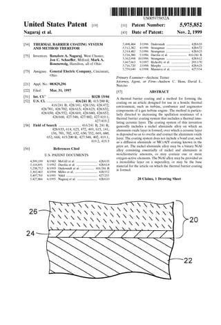
  • 4. 5,975,852 3 the coating System does not include a bond coat, Such as diffusion aluminide and MCrATY coatings known in the prior art. According to the invention, the nickel aluminide alloy may be a binary NiAl alloy consisting essentially of nickel and aluminum in Stoichiometric amounts, or may contain an oxygen-active element, Such as yttrium, cerium, Zirconium or hafnium, to Strengthen the NiAl alloy. Also according to this invention, a component on which the thermal barriercoating is formed may be formed entirely by the nickel aluminide alloy, Such as a single-crystal invest ment casting. Alternatively, the component may be formed by a Superalloy on which the nickel aluminide alloy is provided as a monolithic Surface layer. The processing Steps of the invention generally include providing a component whose Surface is formed by the nickel aluminide alloy, forming an aluminum oxide layer on the nickel aluminide alloy, and then depositing a ceramic layer on the oxide layer. Prior to developing the oxide layer, the Surface ofthe nickel aluminide alloy ispreferably treated to have a Surface finish of not greater than about 25 microinches (about 0.6 micrometer) R, Such as by electropolishing, vapor honing, polishing or light abrasive blasting. According to this invention, a thermal barrier coating System is capable of exhibiting enhanced Service life and Spallation resistance when a nickel aluminide alloy Serves as the Substrate on which an aluminum oxide layer is grown and on which a ceramic layer is deposited. Notably, this invention completely omits a traditional aluminum-based bond coat, instead using a Substantially monolithic NiAl intermetallic from which the component is formed or which forms a thick layer on the component. A Substantially monolithic layer of NiAl may be formed on a component using a process Such as,but not limited to, diffusion bonding an NiAl foil, plasma Spraying, physical vapor deposition or Sputtering. AS Such, the invention completely avoids inter actions that typically occur between bond coats and a Superalloy Substrate on which Such bond coats are formed. In addition, NiAl intermetallic alloys provide a large reser voir for formation ofthe desired aluminum oxide Scale, and are free of elements that might otherwise form Voluminous nonadherent oxides that would otherwise promote Spalla tion. The result is a thermal barrier coating System whose thermal cycle life has been Surprisingly found to be up to about ten times greater than conventional coating Systems. Finally, elimination of the bond coat also yields significant Savings in manufacturing cost and time. Other objects and advantages of this invention will be better appreciated from the following detailed description. BRIEF DESCRIPTION OF THE DRAWINGS The present invention will now be described, by way of example, with reference to the accompanying drawings, in which: FIG. 1 is a perspective view of a high pressure turbine blade; and FIG. 2 is a cross-sectional view of the blade of FIG. 1 along line 2-2, and shows a thermal barrier coating on the blade in accordance with this invention. DETAILED DESCRIPTION OF THE INVENTION The present invention is generally applicable to compo nents that operate within environments characterized by relatively high temperatures, and are therefore Subjected to 15 25 35 40 45 50 55 60 65 4 Severe thermal Stresses and thermal cycling. Notable examples of Such components include the high and low preSSure turbine nozzles and blades, Shrouds, combustor liners and augmentor hardware of gas turbine engines. One such example is the high pressure turbine blade 10 shown in FIG.1. The blade 10 generally includes an airfoil 12 against which hotcombustion gases are directed during operation of the gas turbine engine, and whose Surface is therefore Subjected to Severe attack by Oxidation, corrosion and ero sion.The airfoil 12isanchoredto a turbine disk(notshown) with a dovetail 14 formed on a root section 16 of the blade 10. Cooling passages 18 are present in the airfoil 12 through which bleed air is forced to transfer heat from the blade 10. While the advantages of this invention will be described with reference to the high pressure-turbine blade 10 shown in FIG. 1, the teachings of this invention are generally applicable to any component on which an environmental or thermal barrier coating System may be used to protect the component from its environment. Represented in FIG. 2 is a thermal barrier coating System 20 in accordance with this invention. AS Shown, the coating system 20 includes a ceramic layer 26 bonded to a substrate 22 with an aluminum oxide layer 24. According to the invention, the Substrate 22 is a nickel aluminide alloy of predominantly the beta NiAl phase, and may be in the form of a single-crystal casting that forms the entire blade 10. Alternatively, the Substrate 22 can be limited to a layer on the Surface of the blade 10, which can be formed of a Suitable high-temperature material, Such as a nickel or cobalt-base Superalloy. In this embodiment ofthe invention, the NiAl Substrate 22 can be formed using a suitable deposition process, including low pressure plasma Spraying (LPPS), diffusion bonding, sputtering and electron beam evaporation. A minimal thickness for an NiAl layer is about 125 micrometers in order to provide an adequate Supply of aluminum for oxide formation, as will be discussed below. Anovel feature of this invention is that the thermalbarrier coating system 20 is formed directly on the NiAl Substrate 22 without a bond coat, Such as the diffusion aluminide and MCrATY alloys conventionally required in the prior art. As Such, the Substrate 22 is not prone to interactions and interdiffusion ofelements observed with prior artbondcoats and their Superalloy Substrates. An optional noble metal layer between the NiAl Substrate 22 and the ceramic layer 26,with a thickness ofabout4 to about 10 micrometers, may be included to promote formation of desirable oxides and thereby improve the environmental resistance of the Sub strate 22. This layer would not be deemed a bond coat in accordance with the accepted definition in the art, because Such a thin layer of noble metal (e.g., platinum, rhodium, palladium) would quickly diffuse into the substrate 22 during high temperature processing and Service. To attain a Strain-tolerant columnar grain Structure, the ceramic layer 26 is preferably deposited by physical vapor deposition using techniques known in the art. A preferred material for the ceramic layer 26 is an yttria-Stabilized Zirconia (YSZ), a preferred composition being about 6 to about 8 weight percent yttria, though other ceramic mate rials could be used, Such as yttria, nonstabilized Zirconia, or Zirconia Stabilized by ceria (CeO2) or Scandia (ScC)). The ceramic layer26 is deposited to a thickness that is Sufficient to provide the required thermalprotection for the underlying substrate 22 and blade 10, generally on the order of about 125 to about 300 micrometers. As with prior art bond coats, the surface of the NiAl substrate 22 oxidizes to form the aluminum oxide layer 24 to which the ceramic layer 26 chemically bonds. AS a
  • 5. 5,975,852 S monolithic NiAl alloy, as opposed to a Superalloy or diffu Sion layer that may contain dispersions of aluminides, the Substrate 22 provides a large reservoir from which the oxide layer 24 is formed. The substrate 22 can be formed of the binary NiAl intermetallic, or may be alloyed to contain Selected elements Such as tantalum and hafnium to improve the mechanical and/or physical properties of the Substrate 22. In addition,the NiAl alloy may be alloyed to contain one or more oxygen-active elements, Such as yttrium, hafnium, cerium, Zirconium and others, to promote adherence of the aluminum oxide layer 24. According to this invention, the NiAl Substrate 22 is processed to provide a very Smooth, contaminant-free inter face with the ceramic layer 26, which has been found to unexpectedly promote Spallation resistance of the ceramic layer 26. In particular, Superior results have been achieved by processing the Surface of the Substrate 22 by electropolishing, vapor honing, polishing or light grit blast ing to yield a Surface finish of not more than about 25 microinches (about 0.6 micrometer) R. Such results are unexpected in View of the traditional belief that a rough interface, e.g., an R of at least 50 microinches, is required to achieve acceptable resistance to Spallation with diffusion aluminide bond coats. During the evaluation of this invention, Single-crystal NiAl alloy Specimens and a single-crystal nickel-base Super alloy Specimen were provided with thermal barrier coating Systems that included a thermal insulating ceramic layer of yttria-stabilized zirconia (YSZ) deposited by physical vapor deposition. The coating System for the Superalloy Specimen was also conventionally formed to include a diffusion alu minide bond coat whose Surface was grit blasted to attain a conventionally-suitable surface roughness of about 50 microinches R. In contrast, ceramic layers for the NiAl Specimens were deposited directly on the Surfaces of the NiAl alloy, i.e., without a bond coat. During deposition of the ceramic layers, an oxide layer of about 0.2 to about 0.5 micrometerwas developed. Three different NiAl alloys were evaluated, and theirSurfaces were prepared for deposition of the ceramic layerby either electropolishing or vapor honing as indicated in Table I. Spallation resistance of the coating Systems were evaluated by thermal cycling between room temperature and about 2075° F (about 1135° C). All of the NiAl alloys were the beta-phase NiAl intermetallic, with specific compositions for the NiAl alloys indicated in Table I in atomic percents. TABLE I SPECIMEN SURFACE PREPARATION CYCLES Ni-base superalloy + Grit Blasted 391 Diffusion Aluminide Ni-50A Electropolished 218O N-SOA-O.1Y Electropolished 2040 Ni-49.8A-0.5HF Electropolished 6000 Ni-49.8A-0.5HF Vapor Honed 8OOO “Cycles' denotes the number of cycles Survived without Spallation of the thermal barrier coating. Testing of the Ni-49.8Al-0.5Hf alloys was discontinued without spallation having occurred. From the above, it can be seen that the thermal barrier coatings of the NiAl Specimens were considerably more resistant to Spallation than the Ni-base Superalloy with a conventional diffusion aluminide bond coat. These results were unexpected, in that a large mismatch in coefficients of thermalexpansion existsbetween that ofthe NiAl alloysand 15 25 35 40 45 50 55 60 65 6 the ceramic thermal barrier coating. The anisotropy of the Single-crystal NiAl Specimens was also expected to reduce the Spallation resistance of the thermal barrier coatings of the NiAl Specimens. The above results were also unexpected because the Surfaces of the NiAl alloys were prepared contrary to industry practice, in that a Smoother Surface yielded enhanced Spallation resistance. Both electropolish ing and vapor honing produced a Smooth Surface (an R of about 10 to about 25 microinches, about 0.25 to about 0.6 micrometer) that was generally free of contaminants. In contrast, the diffusion aluminide bond coat of the Ni-base Superalloy was prepared in accordance with Standard prac tice to have a surface finish of about 50 microinches R. The results shown in Table I also indicate the beneficial effect of including about 0.5 atomic percent of an oxygen active element to the NiAl alloy. The Ni-49.8A1-0.5Hf alloys resulted in thermal cycle lives that were longer than that for the stoichiometric NiAl alloy, and considerably longerthan the Ni-base Superalloywith the bond coat. While the Ni-50A1-0.1Yalloy did notexhibit an improved life over the stoichiometric NiAl alloy, the results of the Ni-49.8Al 0.5Hf alloys were concluded to indicate that improved results are obtained if one or more oxygen-active elements are present at levels greater than about 0.1 atomic percent. Accordingly, while NiAl alloys with 0.5 atomic percent hafnium were evaluated, it is believed that similar results would be obtained with NiAl alloys that include about 0.05 to about 1.0 atomic percent of any oxygen-active element, Such as yttrium, hafnium, cerium, Zirconium, etc. While our invention has been described in terms of a preferred embodiment, it is apparent that other forms could be adopted by one skilled in the art. Accordingly, the Scope of our invention is to be limited only by the following claims. What is claimed is: 1. Acomponent formed ofSingle-crystal nickel aluminide intermetallic and having a thermalbarrier coating System on a Surface thereof, the thermal barrier coating System con Sisting of an aluminum oxide layer on the nickel aluminide intermetallic, and a ceramic layer overlying and contacting the aluminum Oxide layer. 2. A component as recited in claim 1, wherein the nickel aluminide intermetallic is a binary NiAl intermetallic con Sisting essentially of nickel and aluminum in Stoichiometric amountS. 3. A component as recited in claim 1, wherein the nickel aluminide intermetallic contains about 0.05 to about 1.0 atomic percent of at least one oxygen-active element. 4. A component as recited in claim 1, wherein the nickel aluminide intermetallic contains about 0.5 atomic percent hafnium. 5. Acomponent as recited in claim 1, wherein the Surface ofthe component has a Surface finish of not greater than 25 microinches R. 6. A component as recited in claim 1, wherein the nickel aluminide intermetallic is Ni-49.8Al-0.5Hf. 7. A component as recited in claim 1, further comprising a noble metal diffusion layer in the surface of the nickel aluminide intermetallic and beneath the aluminum oxide layer. 8. A gas turbine engine component formed of Single crystal nickel aluminide intermetallic of predominantly the beta phase with about 0.05 to about 1.0 atomic percent of at least one oxygen-active element chosen from the group consisting essentially of yttrium, hafnium, cerium and
  • 6. 5,975,852 7 Zirconium, the component having a thermal barrier coating System on a Surface thereof, the thermal barrier coating System consisting of an aluminum oxide layer grown directly from the nickel aluminide intermetallic, and a ceramic layer adhered to the nickel aluminide interme tallic by the aluminum oxide layer. 9. Acomponent as recited in claim 8, wherein the nickel aluminide intermetallic contains about 0.5 atomic percent hafnium. 10. Acomponentas recitedin claim 8, wherein the surface of the component has a Surface finish of not greater than 25 microinches R. 11.Acomponent as recited in claim 8, further comprising a noble metal diffusion layerin the Surface ofthe component beneath the aluminum oxide layer. 12. A component as recited in claim 8, wherein the Single-crystal beta-phase nickel aluminide intermetallic is Ni-49.8A1-0.5Hf. 13. A method comprising the Steps of forming a component of Single-crystal nickel aluminide intermetallic, forming an aluminum oxide layer on a Surface of the component; and 5 15 8 forming a ceramic layer on the aluminum oxide layer. 14. A method as recited in claim 13, wherein the nickel aluminide intermetallic contains about 0.05 to about 1.0 atomic percent of at least one oxygen-active element. 15. A method as recited in claim 13, wherein the nickel aluminide intermetallic contains about 0.5 atomic percent hafnium. 16. A method as recited in claim 13, wherein the nickel aluminide intermetallic is Ni49.8Al-0.5Hf. 17. A method as recited in claim 13, wherein the nickel aluminide intermetallic is of predominantly the beta phase. 18. A method as recited in claim 13, further comprising the Step of Surface finishing the nickel aluminide interme tallic to have a Surface finish of not greater than about 25 microinches R. 19. A method as recited in claim 18, wherein the Surface finishing Step entails an electropolishing, vapor honing or abrasive blasting technique. 20. A method as recited in claim 13, the method further comprising the Step of forminga noble metal diffusion layer in the Surface of the component So as to be beneath the aluminum oxide layer. k k k k k