Us20060000040 a1
•
0 likes•10 views

Inventors and entrepreneurs have vocations fueled by passion. Many would have done it for free or as a hobby if it hadn’t become a profession. Mark Rosenzweig is a natural creator, driven by his passion. This fuel has led Mark to develop his ideas into viable products and innovations that he has been patenting since 2003. From an innovative filter sensor and indicator for vacuum cleaners to a basket for deep fryer and methods of cooking food products to a compact cyclonic bagless vacuum cleaner. Sometimes independently and often as part of creative teams, Mark has patented just under one hundred innovative inventions between 2003 and 2017.

Recommended
More Related Content
Similar to Us20060000040 a1
Similar to Us20060000040 a1 (20)
More from Mark Rosenzweig
Recently uploaded
Recently uploaded (20)
Us20060000040 a1
- 1. (19) United States (12) Patent Application Publication (10) Pub. No.: US2006/000004.0A1 US 20060000040A1 Grey et al. (43) Pub. Date: Jan. 5, 2006 (54) SURFACE CLEANINGAPPARATUS Publication Classification (76) Inventors: Nicholas Gerald Grey, Crowle (GB); (51) Int. Cl. Chad Reese, Auburn, AL (US); Mark A47L II/24 (2006.01) Rosenzweig, Chestnut Hill, MA (US); (52) U.S. Cl. ................................. 15/42; 15/41.1; 15/52.1 Terry Robertson, Auburn, AL (US) Correspondence Address: SHOOK, HARDY & BACON L.L.P. 600 14TH STREET NW SUTE 800 (57) ABSTRACT WASHINGTON, DC 20005-2004 (US) A Surface cleaning apparatus comprises a body including a (21) Appl. No.: 11/040,064 rear compartment, a forward compartment and an interme (22) Filed: Jan. 24, 2005 diate compartment arranged between the rear and forward compartments for collecting debris. An elongate rotatable Related U.S. Application Data brush arrangement is positioned within and extends acroSS 63) Conti f lication No. 10/431,783 the forward compartment. An electric motor is connected to (63) Continuation-in-part of application No. 10/431,783, the rotatable brush arrangement by a belt. A notch or filed on May 8, 2003. opening in the front wall of the forward compartment (60) Provisional application No. 60/564,296, filed on Apr. facilitates admission of particles into the forward compart 22, 2004. ment.
- 2. US 2006/0000040 A1 |}|| ,! |||||1. Patent Application Publication Jan. 5,2006 Sheet 1 of9
- 3. Patent Application Publication Jan. 5, 2006 Sheet 2 of 9 US 2006/0000040A1 N en 2. f
- 4. Patent Application Publication Jan. 5, 2006 Sheet 3 of 9 US 2006/0000040 A1 FIG 3 201 207
- 5. Patent Application Publication Jan. 5, 2006 Sheet 4 of 9 US 2006/0000040 A1
- 6. Patent Application Publication Jan. 5, 2006 Sheet 5 of 9 US 2006/0000040 A1 lf Oe t Q SS O O e Vd C sala N w s CN Cya
- 7. Patent Application Publication Jan. 5, 2006 Sheet 6 of 9 US 2006/0000040 A1
- 8. Patent Application Publication Jan. 5, 2006 Sheet 7 of 9 US 2006/0000040 A1 É
- 9. Patent Application Publication Jan. 5, 2006 Sheet 8 of 9 US 2006/0000040 A1
- 10. Patent Application Publication Jan. 5, 2006 Sheet 9 of 9 US 2006/0000040 A1
- 11. US 2006/0000040 A1 SURFACE CLEANING APPARATUS CROSS-REFERENCE TO RELATED APPLICATIONS 0001. This application is a continuation-in-part of appli cation Ser. No. 10/431,783, filed May 8, 2003. This appli cation also claims priority to the Subject matter of U.S. ProvisionalApplication No. 60/564,296, filedApr. 22,2004. FIELD OF THE INVENTION 0002 This invention relates to a surface cleaning appa ratus, Such as for a floor or upholstery. BACKGROUND OF THE INVENTION 0.003 Conventional surface cleaning apparatus which do not use Suction, Such as Sweeper type floor cleaning appa ratus using rotatable brushes to pick up and collect particles and other debris, typically have a leading front face of the body of the Sweeper apparatus with a Substantially planar lower edge. During use, Such a conventional Sweeper requires a clearance distance to be maintained between the lower edge of the body of the Sweeper apparatus and the Surface to be cleaned. 0004. Ifthe clearance distance between the loweredge of the Sweeper apparatus and the Surface to be cleaned is too small, debris will accumulate in front of the lower edge of the frontface ofthe Sweeperapparatusandwillbe prevented from passing under the lower edge and being Swept up by the bristles of brushes within the body of the apparatus. At present, to remove a piece ofdebris largerthan the clearance between the lower edge and the Surface to be cleaned, it is necessary either to pick up the debrisby hand or to raise the body of the Sweeper apparatus away from the Surface to be cleaned and replace it over the larger debris. On the other hand, ifthe clearance distance between the lower edge ofthe Sweeper apparatus and the Surface tobe cleaned is too great, turbulence caused by the rotation of the bristles can cause debris to be pushed along in front of the Sweeper apparatus asthe Sweeper apparatusis pushed forward.AS the clearance between the lower edge of the body of the Sweeper and the Surface to be cleaned is increased, the efficiency of the Sweeper apparatus in picking up and collecting debris is reduced. 0005 What is needed is a surface cleaning apparatus and cleaning method which is adapted to be able to efficiently pick up debris of varying Sizes without the need to remove the Surface cleaning apparatus from the Surface to be cleaned. SUMMARY OF THE INVENTION 0006. It is therefore an object of the present invention to provide a Surface cleaningapparatus which overcomes, or at least ameliorates, at least Some of the problems of known apparatuS. 0007. In an embodiment, the invention provides a surface cleaning apparatus comprising a body having a forward compartment and a rear compartment, an elongate rotatable brush extending acroSS the forward compartment, and a belt connectinganelectric motorto the rotatablebrush. Thebody includes a front face having a non-planar lower edge Such that the distance between the lower edge and a plane of a Jan. 5, 2006 Surface to be cleaned is not uniform. The non-planar lower edge may be provided as a receSS or notch in the front face. In an embodiment, the lower edge of the front face includes at least one receSS or notch. 0008. In another embodiment, the front wall of the Sur face cleaning apparatus has a lip of increased thickness relative to the thickness of the rest of the front wall. The lip is also at a higher elevation than the bottom Surface of the body. 0009. In still other embodiments, the surface cleaning apparatus includes an intermediate compartment defined by walls between the forward and intermediate compartment, between the rear and intermediate compartment, and the Side walls of the body. The wall between the forward and intermediate compartment can be inclined rearwardly. The wall between the rear and intermediate compartments can Serve to Seal the rear compartment from the intermediate compartment. The intermediate compartment can be in the form of a removable tray, or the intermediate compartment can be emptied by removing a Sidewall. 0010. In an embodiment, the surface cleaning apparatus can also include an auxiliary brush. The auxiliary brush can extend from the forward compartment and canbe connected to the same motor that drives the elongate brush. The auxiliary brushcan also be inclined atan angle relative to the plane of the body of the Surface cleaning apparatus. 0011. In yet other embodiments, the front portion of the Surface cleaning apparatus can be chamfered to increase the extent to which the bristles of the elongate brush protrude from the body. Additionally, a front part of the forward compartment can be removable to increase the extent that the bristles protrude from the Surface cleaning apparatus. 0012. The invention also provides a method for cleaning a Surface, Such as a Surface with large particles of dust or dirt. In an embodiment, a Surface cleaning apparatus having a body, one or more compartments, and a front wall is provided, the front wall having a bottom surface with a lip as well as a notch or opening in the bottom Surface. The body is then tilted forward so that the bottom surface lip contactsa Surface tobe cleaned. One or more particles on the Surface to be cleaned are then admitted into the Surface cleaning apparatus through the receSS or notch. BRIEF DESCRIPTION OF THE DRAWINGS 0013 For a better understanding ofthe present invention and to show more clearly how it may be carried into effect reference will now be made, by way of example, to the accompanying drawings in which: 0014 FIG. 1 is a plan view of one embodiment of a Surface cleaning apparatus according to the present inven tion; 0015 FIG. 2 is a side elevational view, partly in section, of the Surface cleaning apparatus shown in FIG. 1; 0016 FIG. 3 is an perspective view ofa front face ofthe surface cleaning apparatus of FIGS. 1 and 2; 0017 FIG. 4 is an elevational view ofthe surface clean ing apparatus of FIGS. 1 to 3 with an alternative handle; 0018 FIG. 5 is a perspective view of another embodi ment of a Surface cleaning apparatus according to the present invention with a front face removed for clarity;
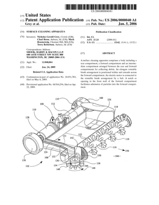
- 12. US 2006/0000040 A1 0.019 FIG. 6 is a perspective view of the apparatus of FIG. 5, with the front face of the housing thereof removed; 0020 FIG. 7 is an underside view of the apparatus of FIG. 5 with the front face removed for clarity; 0021 FIG. 8 is perspective view of another embodiment of a Surface cleaning apparatus according to the invention. 0022 FIG. 9 is an underside view of the apparatus of FIG 8. DETAILED DESCRIPTION OF THE INVENTION 0023. In an embodiment corresponding to the surface cleaning apparatus shown in FIGS. 1 to 3, the Surface cleaning apparatus comprises a body 1, Suitably moulded of plastics material, and having at least two compartments and preferably at least three compartments. 0024. A rear compartment 3 houses an electric motor 5 and a rechargeable battery pack 7. The battery pack 7 may be connected to a mains power Supply (not shown) for recharging the battery pack. The battery pack may either be connected to the mainsSupply whenever the apparatus is not in use or atSuitable times when the battery pack hasbecome depleted. Switch means (not shown) is provided to permit a user to energise and de-energise the motor 5 as desired. AS an alternative to a rechargeable battery pack, the apparatus could employ disposable batteries or be mains powered, Such asbeing adapted to operate by plugging into household electric current. 0.025 Aforward compartment9 houses anelongate rotat able brush arrangement 11. The brush arrangement 11 is rotated in a direction denoted by arrow 19, such that an upperSurface ofthe brush arrangement is rotated away from the rearcompartment3. Forconvenience a forward wall201 ofthe forward compartment9 is arcuate and extends around the periphery ofthe brush arrangement 11.The bottom ofthe forward compartment is open at 13 to allow the bristles of the brush arrangement to contact a floor, carpet or the like over which the Surface cleaning apparatus is to be moved. 0026. In an embodiment, the forward wall 201 of the forward compartment is also the front wall 201 of the Surface cleaning apparatus. The lower edge 203 of the front wall 201 is non-planar, as shown in FIG. 3. The lower edge 203 incorporates a recess 205 with a width in a range from about20mm to about 150 mm, preferably about 60 mm.The depth of the recess, that is the distance between the top 207 of the recess 205 and the lowest portion 209 of the lower edge 203 is nominally about 10 mm but may, for example, be in the range from about4 mm to about 20mm. The recess allows debris, Such as dust, dirt and the like, too large to pass under the lowest portion 209 of the lower edge 203 to pass into the forward compartment and be picked up by means of the brush arrangement 11. Turbulence causedby the rotation of the brush assembly, which could cause relatively small debris to be pushed along in front of the Surface cleaning apparatus, is minimized as the majority ofthe lower edge is maintained in Sufficiently close proximity to the Surface to be cleaned. The distance between the Surface to be cleaned and the lowest portion 209 of the lower edge 203 is nominally about 10 mm but may, for example, be in the range from about 4 mm to about 20 mm. Jan. 5, 2006 0027. In another embodiment, the bottom surface of the front wall is elevated relative to the bottom Surface of the body to create Space for admitting particles into the forward compartment during the operation of the Surface cleaning apparatus. For example, in the embodiment shown in FIG. 8, bottom surface 203 of the front wall 201 is higher in elevation than the bottom of body 1. Front wall 201 also includes a notch or opening205. The notch or opening 205 increases the distance between the bottom Surface 203 ofthe front wall and the Surface being cleaned in the region of the notch. This allows larger particles be admitted through the notch and into the compartments of the Surface cleaning apparatus. The notch 205 can be located anywhere on the frontwall. Conveniently,the notch oropeningcan be located in the center ofthe front wall, as this allows a user to easily align the notch with a particle to be Swept. Bottom Surface 203 of front wall 201 further comprises a lip 92 which has an increased thickness relative to the front wall 201. If the Surface cleaning apparatus is tipped forward So that the bottom Surface of the front wall comes into contact with a surface being cleaned, lip 92 reduces the likelihood that the bottom surface ofthe front wall will “digin' to the surface. Instead, the thicker lip will more evenly distribute weight, making it easier to move the Surface cleaning apparatus while being tipped forward. 0028. The height of the notch or opening should be Sufficient to allow particles to be taken into the intermediate compartment while the body is being tipped forward. In an embodiment, the height ofthe opening relative to the bottom Surface of the front wall is the same as the distance from the bottom Surface of the front wall to the bottom of the Surface cleaning apparatus body. For example, ifthe bottom Surface of the front wall is higher in elevation than the Surface to be swept by 1 cm (when the body is not tipped forward), the elevation of the bottom Surface in the notch relative to the bottom Surface of the rest of the front wall would also be 1 cm. This would lead to a total elevation for the bottom Surface of the opening of 2 cm relative to a Surface to be cleaned. 0029. The width of the notch or opening can be of any convenient size, as long as the width is Small enough to prevent undue stress on the front wall when the body is tipped forward to bring the bristles into closer contact with a Surface. Thus, the notch or opening can have various widths, as the width of the front wall could range from as Small as 4 inches to as large as 20 inches. Other common widths for the front wall include 8 inches, 10 inches, 11.5 inches, 13 inches, 14 inches, and 15 inches. In an embodi ment, the width of the opening is at least 10% of the width of the front wall and preferably at least 15%. In an embodi ment, the width of the opening is 33% or less of the width ofthe front wall and preferably 25% orless. FIGS.3,8, and 9 show examples of a notch or opening 205 in a front wall 2O1. 0030 The rear of the forward compartment is a rear wardly inclined wall 15 which allows debris to be propelled up the wall due to rotation of the brush arrangement 11 and to pass over the wall into an intermediate compartment 17 which will be described in more detail hereinafter. The wall 15 extends upwardly to about the same height as the top of the brusharrangement11and isangledrearwardly(i.e. away from the forward compartment) at an angle of about 18 degrees. The precise angle is not important, but the incli
- 13. US 2006/0000040 A1 nation facilitates the passage of the debris up and over the wall and at the same time facilitates retention of the debris within the intermediate compartment 17.The brush arrange ment extends substantially the entire width of the forward compartment and is provided with two helically arranged rowsofbristles. The two rows are diametrically opposedand each row is in the form of a pair of Separate helices which twist in opposite directions and meet Substantially midway between the ends of the brush arrangement. 0031. The intermediate compartment 17 is positioned between the wall 15 and a wall 21 which encloses the electrical components 5, 7 in the rear compartment 3, the wall 21 protecting the components in the rear compartment from the ingress ofdebris. The intermediate compartment 17 also has a lower wall, an upper wall and Side walls formed by the outer wall of the body 1. Debris therefore accumu lates within the intermediate compartment 17. The interme diate compartment is provided with a removable closure to facilitate the removal of debris. For example, one of the walls, Such as a Side wall, the upper wall or the lower wall, can be removed in order that the debris can be emptied from the intermediate compartment, the removed wall being replaced once the compartment has been emptied. The removable wall may comprise a clear Section to enable a user to determine when the intermediate compartment requires emptying. Ideally, Side wall 23 is removable for emptying purposes. The wall 15 provides the advantage that debris does not readily escape from the intermediate com partment 17 and, even if the body of the Surface cleaning apparatus is inclined Such that the forward compartment is below the intermediate compartment, the debris does not escape from the intermediate compartment. Alternatively, the intermediate compartment can comprise a removable tray. In Such an embodiment, the Side wall23 can form a part of the removable tray. 0032. In an embodiment, the brush arrangement 11 is rotated by the motor 5 by way of toothed rollers 25, 27 attached to the motor and to the brush, respectively, and by way of a toothed belt 29, for example of elastomeric material, extending around the two rollers. The toothed belt 29 isenclosed within a tunnel 31 where itpassesthrough the intermediate compartment 17 in order to prevent the ingreSS of debris into the rear compartment 3. The tunnel 31 may pass through the intermediate compartment 17 at any con Venient point. However, particularly in the event Side wall 23 is removable for emptying purposes, the tunnel may be arranged at that Side of the intermediate compartment 17 remote from the side wall 23. 0033. In an embodiment, a handle 33 is attached to the body 1 in the region of the rear compartment 3, the body being formed with a recess 35 beneath the handle to allow the handle to be gripped while maintaining a low profile for the Surface cleaningapparatus. The handle 33 may be in two parts, a first part 37 which is secured to the body 1 and a second part39 which can be removed from the first part and replaced by a longer handle part41 asshown in FIG. 4. The longer handle part 41 is provided with Swivel means 43 to allow the handle part 41 to rotate about the axis thereof relative to the body 1 and with pivot means 45 to allow the handle part to pivot about an axis transverse to the axial direction of the handle part to enable the Surface cleaning apparatus to be Steered by the user. AS an alternative to interchangeable handles, the handle part 41 may be remov Jan. 5, 2006 ably engageable with the handle part33. In Such a case, the handle part 33 is arranged such that the Swivel means 43 functions only in certain positions of the handle part 33 in order that movement can be inhibited when the handle part 33 is used alone. 0034. In some embodiments, the bristles of the brush arrangement 11 can extend outwardly from the aperture in the lower face of the forward compartment 9, as shown for example in FIG. 4. In order to remove stubborn debris and/or to revitalise carpet, the lower edge of the front wall of the forward compartment may be chamfered, or the front wall may be movable (includingremovable), to increase the exposure of the bristles in this region. In this way, the forward part ofthe apparatus may be inclined relative to the Surface to be cleaned, thereby increasing contact between the bristles and a Surface to be cleaned and, on Some Surfaces, increasing the depth to which the bristles penetrate and clean the Surface. 0035 FIG.8 shows the profile ofa forward compartment according to another embodiment of the invention. In this embodiment, bottom Surface 203 ofthe front wall201 ofthe forward compartment is chamfered and at a higher elevation relative to the Surface being Swept than the bottom Surface of the body. The higher elevation of bottom surface 203 is achieved by having the side wall of the forward compart ment rise at an angle away from the Surface to Swept. In an embodiment, this angle is at least 5 degrees and preferably at least 10 degrees. In an embodiment, this angle is 20 degrees or less, preferably 15 degrees or leSS. Additionally, the bottom surface 203 of the faceplate is also angled away from the surface to be cleaned. The angle of the bottom Surface relative to the Surface to be cleaned can be any convenient angle, Such as the same angle as the rise angle of the sidewall of the forward compartment relative to the Surface beingSwept. In an embodiment, this angle is at least 5 degrees and preferably at least 10 degrees. In an embodi ment, this angle is 20 degrees or less, preferably 15 degrees or less. In another embodiment, the front wall 201 may be movable (including removable) to increase the exposure of bristles to a Surface to be cleaned. 0036) An auxiliary rotary brush 11 may also be provided at the Side of the brush arrangement 11 which incorporates the roller 27 and the belt 29. Such an auxiliary brush is described, for example, in GB-A-1 547 286. Such an aux iliary brush is able to Sweep debris into the path ofthe brush arrangement 11 which might otherwise be missed due to the lack of bristles in the region of the roller 27. The auxiliary brush may be driven by any Suitable means, Such as gearing from the brusharrangement 11 orby friction withthe surface to be Swept, and is Suspended from and extends outwardly beyond the body 1. The auxiliary brush may comprise a cylindrical body rotatable about an axis which is inclined to the vertical by about 10 degrees so as to extend outwardly beyond the body 1. Bristles protrude radially outwardly from the periphery of the cylindrical body, but need not be perpendicular to the axis of rotation and may preferably be at an angle of about 80 degrees to the axis of rotation So as to form a cone which increases in cross-section with increas ing distance from the body 1. 0037. In another embodiment, the front wall 201 of the forward compartment 9 may be removed to expose the bristles at the front of the apparatus. This effectively
- 14. US 2006/0000040 A1 increases the aperture in the forward compartment which wouldSeriously impair the effectiveness ofa Suctioncleaner, but in the present invention can effectively be used to assist in the Sweeping ofStairs, cleaning upholstery and carpets in vehicles and the like operations where a greater exposed area ofbristles can be useful. As an alternative to removing the front wall of the compartment 9, the front wall may be movable, for example pivotable or slidable, relative to the remainderofthe compartmentin ordertoexpose thebristles. 0.038 Although not shown, the rear compartment 3 may be provided with ground-engaging wheels in order to assist mobility of the Surface cleaning apparatus. The ground engaging wheels may, for example, be formed externally in the Side regions of the rear compartment 3 or may be provided within recesses formed at least partly beneath the rear compartment 3. 0039. Although the illustrated embodiments of the present invention are intended primarily for domestic use, the Surface cleaning apparatus can also be used outdoors or in workshops if desired. However, it may be preferable to provide a more rugged design specifically adapted for Such Sc. 0040. In use of the Surface cleaning apparatus according to various embodiments of the invention, the apparatus is placed upon a Surface to be Swept, Such as a carpet, and the Switch is operated to energise the motor. This rotates the brush arrangementto allow intake (Sweeping)ofdebris from the Surface and then propels the debris up and over an inclined wall and into an intermediate compartment where it is temporarily Stored. AS the Surface cleaning apparatus is moved over the Surface with the brush arrangement rotating, any further debris is similarly swept from the surface and propelled up and over the inclined wall and into the inter mediate compartment. If there is a piece of relatively larger debris, the Surface cleaning apparatus can be Steered Such that the receSS in the front wall of the apparatus is passed over the larger debris and the debris is picked up by the rotating brush arrangement. 0041. In another embodiment, the surface cleaning appa ratus can be tilted forward to bring the bristles into closer contact with the floor. For example, the apparatus could be tilted forward on a Soft carpet Surface in order to bring the rotating brush into greater contact with the Surface being swept. In this situation, the lip of the bottom surface of the front wall can come into contact with the Surface being Swept, reducing the clearance between the bottom Surface of the frontwall and the Surface beingSwept.This increases the contact between the brush and the Surface being Swept. Additionally, because of the notch in the front wall, the risk thatparticles may be pushed outofthe way rather than being collected by the Surface cleaning apparatus is greatly reduced. The notch or opening increases the distance between the bottom Surface of the front wall and the Surface being cleaned in the region of the notch. When the body is tilted forward, the notch facilitates intake of debris. By admitting a piece of debris through the notch, the piece of debris can be readily Swept into the intermediate compart ment. The notch can be located anywhere on the front wall. Conveniently, the notch or opening can be located in the center of the front wall, as this allows a user to easily align the notch with a particle to be Swept. 0042. The Surface cleaning apparatus is extremely por table and can be employed wherever it may be required. For Jan. 5, 2006 example, it can be used to Sweep Stairs without the need for electrical leads or Suction hoses. The shape ofthe apparatus with the rounded shape of the rear compartment as illus trated facilitates movement of the apparatus over Stairs, but ground engaging wheels may be provided to further facili tate Such Sweeping operations. 0043. When the intermediate compartment is to be emp tied, one wall of the compartment is removed as explained above and the debris can readily be discharged. The remov able wall is then replaced. Alternatively, the intermediate compartment may be in the form of a tray which can be removed andemptiedSo as to discharge debris.The tray may comprise a Section which is clear to enable a user to determine when the intermediate compartment requires emptying. 0044) When the surface cleaning apparatus is not in use it can be Stored, for example either in a cupboard or the like or plugged into a mains Supply in order to recharge the battery 7. 0045. In variousembodiments,the surface cleaningappa ratus according to the invention incorporates an electrically driven brush arrangement. The brush arrangement is not driven by frictional forces between the Surface cleaning apparatus and the Surface overwhich it isto be moved. Thus, efficiency of the apparatus is not dependent on the nature of the frictionalcontact. Further, the apparatus does not rely on Suction means to draw the debris into a storage chamber. Thus, efficiency of the apparatus is not dependent on the effectiveness of Suction means and the Substantial power drain of Suction means on the rechargeable battery is avoided. In an alternative embodiment, however, the Surface cleaning apparatus ofthis invention can be incorporated into a vacuum cleaner. 0046) The provision of the motor at the rear of the apparatuseliminatesthe needforincreasedheightshould the motor be positioned over the compartment for collecting dust and the like and also provides effective full width cleaning which would not be possible if the motor was to be positioned within the compartment for collecting debris. In anotherembodiment, the drive means for the brush arrange ment passes at least partly through the debris compartment. 0047 FIGS. 5, 6 and 7 depict another embodiment of a Surface cleaningapparatusaccordingto the invention. Appa ratus 102 for cleaning a Surface 104 comprises a housing 106, Suitably of moulded plastics material, and effectively having three compartments. Arear compartment 108houses an electric motor 110 and a rechargeable battery pack 112. The battery pack 112 may be connected to a mains power Supply (not shown) for recharging the battery pack. The battery pack may either be connected to the mains Supply whenever the apparatus is not in use or at Suitable times when the battery pack has become depleted. Switch means 113 is provided to permit a user to energise and de-energise the motor 110 as desired. AS an alternative to a rechargeable battery pack, the apparatus could employ disposable batter ies or be mains powered. 0048. Aforward compartment 114houses a transversely arranged elongate rotatable brush arrangement 116, with bristles 118. Such elongate rotatable brush arrangement 116 is sometimes known as a brush bar. The bottom of the forward compartment 114 is open at 120 to allow the bristles
- 15. US 2006/0000040 A1 118 ofthe elongate brush arrangement 116 to contact a floor, carpet or the like over which the apparatus is to be propelled. The rear of the forward compartment is a rearwardly inclined wall 122 which allows debristo be propelled up the wall due to rotation ofthe brush arrangement 116and to pass over the wall into an intermediate compartment 124. The front of the forward compartment is provided with a front wall (not shown) which comprises the front face ofbody of the apparatus and which may be removable if desired. Debris accumulating in the intermediate compartment 124 can be removed by opening a cover 126. The wall 122 extends upwardly to about the Same height as the top of the elongate brush arrangement 116 and may be angled rear wardly (i.e. away from the forward compartment) Such as at an angle of about 18 degrees. The precise angle is not important, but the inclination facilitates the passage of the debris up and over the wall 122 and at the same time facilitates retention of the debris within the intermediate compartment 124. 0049. The elongate brush arrangement 116 is rotated by the motor 110 by way of toothed rollers 128, 130 attached to the motor and to the brush arrangement, respectively, and by way of a toothed belt 131, for example of elastomeric material, extending around the two rollers. The toothed belt 131 is enclosed within a tunnel 132 where it passes through or alongside the intermediate compartment 124 in order to prevent the ingress of debris into the rear compartment 108. 0050. An auxiliary brush means 134 is provided extend ing in an additional housing 170 outwardly from the appa ratus housing 106 at the right hand Side of the elongate rotatable brush arrangement 116 as viewed from above and behind the apparatus 102. The auxiliary brush means 134 is of Substantially circular form and is Supported for rotation about an axis 136, which may be vertical or inclined to Vertical, Such as at an angle of about 10 degrees to Vertical. The auxiliary brush means 134 has abody 138provided with radial bristles 140 which are inclined at an acute angle to the axis of rotation 136 so as to effectively form a conical arrangement increasing in cross-section with increasing dis tance from the body 138. 0051. The auxiliary brush means 134 is rotatably driven from the rotating elongate brush arrangement 116 by a gear wheel 142 at the end ofthe elongate brush arrangement 116 which meshes with a further gear wheel 144 on the body 138 ofthe auxiliary brush means 134. The auxiliary brush means 134 is caused to be rotated in an anti-clockwise direction denoted by arrow 146, as viewed from above and behind the apparatus 102. During Such rotation of the auxiliary brush means 134, a peripheral region thereof rotates from a sideways-directedposition 148(FIG.7)outside thehousing 106 to an opposed sideways-directed position 150 covered by the housing 106, through a forwardly-directed position 152. 0052. The apparatus 102 is providedwith a handle 154by means of which it can be propelled at least in a forwards direction 156. Wheels 158 and 160 are provided to enable or assist manual propulsion of the apparatus acroSS the Surface 104 to be swept, such as a floor, stairway or upholstery. The handle 154 could be longer, or be of a different shape or form, as required. 0053. The rotating auxiliary brush means 134 does not rely on contact with the surface 104 for its rotation and Jan. 5, 2006 therefore provides more efficient Sweeping of edge regions ofthe surface 104 regardlessofthe nature ofthe surface 104. Furthermore, the direction of rotation 146 of the auxiliary brush means 134 ensures that debris is swept positively by the auxiliary brush arrangement 134into a position ahead of the rotating elongate rotating brush assembly 116, ready to be picked up by the elongate brush arrangement 116. 0054 If desired, instead of or in addition to the auxiliary brush means 134 provided extending outwardly from the right hand side of the housing 106, a similar auxiliary brush means(not shown) could likewise be provided extending in an additional housing outwardly from the left hand side of the housing 106 and driven from the opposite end of the elongate brush arrangement 116. Such additional or alter native auxiliary brush means differs from the auxiliary brush means 134 only in that it is caused to rotate in a clockwise, rather than anti-clockwise, direction as viewed from above and behind the apparatus 102. 0055. The additional housing 170 and the front wall 201 of the Surface cleaning apparatus may be attached to the main housing 106 by means ofclips(notshown). Therefore the additional housing 170 and the front wall 201 can be detached from the main housing 106 of the apparatus without the need for tools, to facilitate maintenance and/or repair of the elongate brush arrangement 116 and the aux iliary brush means 134. 0056 Instead of the apparatus 102 being provided with a battery or mains powered electric motor 110 to drive the elongate brush arrangement 116 and hence the auxiliary brush means 134, a known form offriction drive means(not shown), resulting from propulsion of the apparatus 102 along the surface 104, may be utilised to effect rotation of the elongate brush arrangement 116 and hence rotation of the auxiliary brush means 134. 0057 Although the front wall of the surface cleaning apparatus has been described as comprising a single receSS Such that the lower edge of the wall is non-planar it should be understood that the wall can comprise a plurality of recesses, or the lower edge can have an undulating Surface Such that the distance between the lower edge and the Surface being cleaned can vary depending on the undula tions. 0058 Persons of ordinary skill in the art will recognize that many modifications may be made to the present inven tion without departing from the Spirit and Scope of the present invention. The embodiments described herein are meant to be illustrative only and should not be taken as limiting the invention, which is defined by the following claims. 1. A Surface cleaning apparatus, comprising: a) a body having a forward compartment and rear com partment; b) an elongate rotatable brush extending across the for ward compartment; and c) a belt connecting an electric motor and the rotatable brush; wherein Said forward compartment comprises a front wall having a notch for admitting larger particles into Said forward compartment.
- 16. US 2006/0000040 A1 2. The apparatus of claim 1, wherein Said front wall of Said forward compartment has a thickneSS and further com prises a bottom Surface at a higher elevation than a bottom surface of the body, and wherein the bottom surface ofsaid front wall has a lip of increased thickness relative to Said thickness of said front wall. 3. The apparatus of claim 2, wherein the bottom surface ofSaid front wall is inclined at an angle relative to the plane of the body. 4. The apparatus of claim 1, further comprising an aux iliary brush extending from the forward compartment and driven by the electric motor. 5. The apparatus of claim 4, wherein the auxiliary brush and the elongate rotatable brush are connected by a gear. 6. The apparatus of claim 1, wherein an intermediate compartment is defined by a wall between the forward compartment and the intermediate compartment, a wall between the intermediate compartment and the rear com partment, and Side walls. 7. The apparatus ofclaim 6, wherein the wallbetween the forward and intermediate compartments is inclined rear wardly. 8. The apparatus ofclaim 7, wherein the wallbetween the forward and intermediate compartments has an angle of inclination of from 15 to 20 degrees. 9. The apparatus ofclaim 6, wherein the wall between the intermediate and rear compartments Seals the rear compart ment from the intermediate compartment. 10. The apparatus of claim 6, wherein the intermediate compartment comprises a removable tray. 11. The apparatus of claim 1, wherein a front part of the forward compartment is movable to expose bristles on the elongate rotatable brush at the front part of the forward compartment. 12. The apparatus ofclaim 1, wherein a lower front region of the body is chamfered to increase the extent to which the bristlesprotrude from the body in the region ofthe chamfer. 13. The apparatus of claim 1, wherein the electric motor is located in the rear compartment. 14. A Surface cleaning apparatus, comprising: a) a body having a forward compartment and rear com partment; b) an elongate rotatable brush extending across the for ward compartment; and c) a belt connecting an electric motor and the rotatable brush; Said forward compartmentcomprising a front wall having a thickneSS and having a bottom Surface at a higher elevation than a bottom Surface of Said body, wherein the bottom surface of said front wall has a lip of increased thickneSS relative to Said thickness of Said front wall. 15. The apparatus of claim 14, wherein said bottom Surface is inclined at an angle relative to the plane of the body. 16. The apparatus ofclaim 14, wherein said front wall of Said forward compartment further comprises a notch for admitting larger particles into Said forward compartment. 17. The apparatus of claim 14, further comprising an auxiliary brush extending from the forward compartment and driven by the electric motor. Jan. 5, 2006 18.The apparatus ofclaim 17, wherein the auxiliary brush and the elongate rotatable brush are connected by a gear. 19. The apparatus of claim 14, further comprising an intermediate compartment defined by a wall between the forward compartment and the intermediate compartment, a wall between the intermediate compartment and the rear compartment, and Side walls. 20. The apparatus of claim 19, wherein the wall between the forward and intermediate compartments is inclined rear wardly. 21. The apparatus of claim 20, wherein the wall between the forward and intermediate compartments has an angle of inclination of from 15 to 20 degrees. 22. The apparatus of claim 19, wherein the wall between the intermediate and rear compartments Seals the rear com partment from the intermediate compartment. 23. The apparatus of claim 19, wherein the intermediate compartment comprises a removable tray 24. The apparatus of claim 14, wherein the lower front region of the body is chamfered to increase the extent to which the bristles protrude from the body in the region ofthe chamfer. 25. The apparatus ofclaim 14, wherein a front part of the forward compartment is movable to expose bristles on the elongate rotatable brush at the front part of the forward compartment. 26. The apparatus ofclaim 14, wherein the electric motor is located in the rear compartment. 27. A method for cleaning a Surface, comprising: providing a Surface cleaning apparatus comprising a body, one or more compartments in Said body, and a front wall, Said front wall comprising a bottom Surface lip at a higher elevation than a bottom Surface ofthe body and a notched region in the center of the front wall, the bottom surface lip in the notched region being at a higher elevation than the bottom Surface lip in the adjacent portions of the faceplate; tilting Said body forward So that at least a portion of the bottom Surface lip contacts the Surface to be cleaned; and admitting one or more particles into a compartment in Said body through Said notched region. 28. The method of claim 27, wherein said bottom Surface lip has an increased thickness relative to a thickness of Said front wall. 29. The method of claim 28, wherein said bottom Surface lip is inclined at an angle relative to the plane of the body. 30. The method of claim 27, wherein the portion of the bottom Surface lip contacting the Surface to be cleaned is kept in contact with the Surface to be cleaned while admit ting Said one or more particles. 31. The method of claim 27, wherein particles admitted through Said notched region are admitted into a forward compartment. 32. The method of claim 27, wherein particles admitted through Said notched region are collected in an intermediate compartment. 33. The method of claim 32, wherein the apparatus comprises a motor in a rear compartment, and wherein a
- 17. US 2006/0000040 A1 wall between the intermediate and rear compartments Seals the rear compartment from the intermediate compartment. 34. The method ofclaim 27, wherein a lower front region ofthe body including the front wall is chamfered to increase the extent to which the bristlesprotrude from the body in the region of the chamfer. 35. A method for cleaning a Surface, comprising: providing a Surface cleaning apparatus comprising a body, a forward compartment and a rear compartment, and a front wall, Said front wall comprising a bottom Surface lip and a notched region in the center of the front wall; tilting Said body forward So that at least a portion of the bottom Surface lip contacts the Surface to be cleaned; and admitting one or more particles into a compartment in Said body through Said notched region. 36. The method ofclaim 35, wherein said bottom Surface lip is at a higher elevation than a bottom Surface ofthe body. 37. The method of claim 35, wherein the bottom Surface lip has an increased thickness relative to a thickness of Said front wall. Jan. 5, 2006 38. The method of claim 35, wherein the bottom Surface lip is inclined at an angle relative to the plane of the body. 39. The method of claim 35, wherein the portion of the bottom Surface lip contacting the Surface to be cleaned is kept in contact with the Surface to be cleaned while admit ting Said one or more particles. 40. The method ofclaim 35, wherein the surface cleaning apparatus further comprises an intermediate compartment. 41. The method of claim 40, wherein particles admitted through Said notched region are collected in an intermediate compartment. 42. The method of claim 41, wherein the apparatus comprises a motor in a rear compartment, and wherein a wall between the intermediate and rear compartments Seals the rear compartment from the intermediate compartment. 43. The method of claim 35, wherein the bottom Surface lip in the notched region is at a higher elevation than the bottom Surface lip in the adjacent portions of the faceplate. 44. The method ofclaim 35, wherein a lower front region ofthe body including the front wall is chamfered to increase the extent to which the bristlesprotrude from the body in the region of the chamfer.