SlideShare a Scribd company logo
1 of 8
Download to read offline
US 2004O115462A1
(19) United States
(12) Patent Application Publication (10) Pub. No.: US2004/0115462A1
Grady et al. (43) Pub. Date: Jun. 17, 2004
(54) ARTICLE INCLUDING ASUBSTRATE WITH (22) Filed: Dec. 13, 2002
A METALLIC COATING AND A
PROTECTIVE COATING THEREON, AND Publication Classification
ITS PREPARATION AND USE IN
COMPONENT RESTORATION (51) Int. Cl." ..................................................... B32B 15/00
(52) U.S. Cl. ............................................ 428/615; 428/621
(76) Inventors: Wayne Ray Grady, Fairfield, OH (US);
Thomas Joseph Kelly, Cincinnati, OH (57) ABSTRACT
(US); Michael James Weimer,
Loveland, OH (US); Nripendra Nath A coated article has a metallic substrate with a Substrate
Das, West Chester, OH (US); Mark composition, and a metallic coating overlying and contact
Alan Rosenzweig, Hamilton, OH (US) ing the metallic Substrate. The metallic coating has a metal
lic-coating composition different from the Substrate compo
Correspondence Address: Sition.Aprotective coatingoverlies andcontactsthe metallic
MCNEES, WALLACE & NURICK coating. The protective coating includes an aluminide layer
100 PINE STREET overlyingandcontactingthe metallic coating, and optionally
BOX 1166 a thermal barrier coating overlying and contacting the alu
HARRISBURG, PA 17108 (US) minide layer. This structure may be used to restore a key
dimension of an article that has previously been in Service
(21) Appl. No.: 10/318,760 and to protect the article as well.
Patent Application Publication Jun. 17, 2004 Sheet 1 of2 US2004/0115462A1
F/G, /
Patent Application Publication Jun. 17,2004 Sheet 2 of 2 US2004/0115462 A1
F-/G. 5
Aeol//ZA ZaAs/7 Z26A2S/7
M1A77AA/C A-7A7AAA /C. Aao 7Aa 7/Va
/a 77CA at CO477/vg (a/27/M6
US 2004/0115462 A1
ARTICLE INCLUDINGA SUBSTRATE WITH A
METALLIC COATING AND A PROTECTIVE
COATING THEREON, AND ITS PREPARATION
AND USE IN COMPONENT RESTORATION
0001. This invention relates to the protection of a sub
Strate using a protective coating and, more particularly, to
the restoration ofa key dimension ofan article Such as a gas
turbine component that has previously been in Service.
BACKGROUND OF THE INVENTION
0002 In an aircraft gas turbine (jet) engine, air is drawn
into the front of the engine, compressedby a Shaft-mounted
compressor, and mixed with fuel.The mixture isburned, and
the hot combustion gases are passed through a turbine
Section mountedon the same shaft. In the turbine Section, the
hot combustion-gas flow passes between pairs of turbine
Vanes(alsosometimes termed the “nozzles”), which redirect
the combustion-gas flow slightly, and impinges upon the
turbine blades. The impingement of the flow of hot com
bustion gas against an airfoil Section of the turbine blades
turns the shaft and provides power to the compressor. The
hot exhaust gases flow from the back of the engine, driving
it and the aircraft forward.
0003. The hotter the combustion and exhaust gases, the
more efficient is the operation ofthe jetengine. There is thus
an incentive to raise the combustion and exhaust gas tem
peratures. However, at these high temperatures the combus
tion-gas flow is highly corrosive, erosive, and oxidative to
the materials it contacts. The maximum temperature of the
combustion gases is normally limited by the materials used
to fabricate the turbine components of the engine, including
the turbine blades and Vanes. The turbine components must
have the necessary Strength, but also be resistant to the
environmental damage caused by the combustion-gas flow,
at the operating temperature. In current engines, the turbine
Vanes andblades are made ofcobalt alloys and nickel-based
Superalloys, and can operate at temperatures of up to about
1800-2100 F. These components are subject to environ
mental damage by corrosion, erosion, and oxidation at those
temperatures.
0004. Many approaches have been used to increase the
operating temperature limits and Service lives of the turbine
blades and Vanes to their current levels, while achieving
acceptable environmental resistance. The composition and
processing of the base materials themselves have been
improved. Cooling techniques are used, as for example by
providing the component with internal cooling passages
through which cooling air is flowed.
0005. In another approach used to protect the turbine
Section components, a portion of the Surfaces of the turbine
blades orVanes is coated with a protective coating. One type
ofprotective coating includes an aluminum-containing pro
tective coating deposited upon the Substrate material to be
protected. The exposed Surface of the aluminum-containing
protective coating oxidizes to produce an aluminum oxide
protective Scale that protects the underlying Surface. A
ceramic thermal barrier coating may be applied over the
aluminum-containing protective coating to further protect
and insulate the Substrate.
0006 Despite careful selection of the base materials and
protective coating, after agasturbine component hasbeen in
Jun. 17, 2004
Service, it is usually eroded, corroded, and oxidized So that
one or more key dimensions of the component may be
reduced below respective minimum permissible dimen
Sional values. An example relates to the throat Separation
dimension between each adjacent pair of gas turbine Vanes,
the Space through which the hot combustion-gas flows from
the combustor on its way to contact the turbine blades. The
throat dimension between two adjacent gas turbine Vanes
has its maximum permissible dimensional value that cannot
be exceeded without reducing the performance and effi
ciency of the gas turbine. When the gas turbine Vanes are
operated in Service, their Surfaces are worn away So that a
key thickness dimension ofthe Vanesbecome dimensionally
Smaller. Consequently, the Vane-to-vane gas-flow throat
Separation dimension becomes larger and the maximum
permissible throat-Separation dimensional value is eventu
ally exceeded as the key thickness dimension of the Vanes
fallsbelow its minimum permitted key thickneSS dimension.
0007. The gas turbine components are expensive to fab
ricate, and it is therefore desirable, where feasible and the
Service damage is not too great, to repair and restore them,
rather than to discard them. No restoration procedure has
been proposed for these protected components to restore
dimensions and also to restore the protective Structure, and
therefore a need exists for Such a restoration procedure. The
present invention fulfills this need, and further provides
related advantages.
SUMMARY OF THE INVENTION
0008. The present approach provides an article that is
protected against environmental damage, and is also dimen
Sionally controlled. The approach may be used to restore
dimensions of articles that have previously been in Service,
and whose dimensions are reducedbelow minimum permis
Sible dimensional values during that Service. It may also be
used with newly made articles if their dimensions must be
increased.
0009. A coated article comprises a metallic substrate
having a Substrate composition and a metallic coating over
lying and contacting the metallic Substrate. The metallic
coating has a metallic-coating composition different from
the Substrate composition. The metallic-coatingcomposition
must be readily and controllably depositable in thin layers,
such as those in the range offrom about 0.003 to about 0.015
inch, but at a rate Sufficiently high to be economically
feasible. A protective coating overlies and contacts the
metallic coating. The protective coating comprises an alu
minide layer overlying and contacting the metallic coating
and, optionally, a ceramic thermal barrier coating overlying
and contacting the aluminide layer.
0010. In a case of interest, the substrate is a component
of a gas turbine engine, Such as a turbine blade or turbine
Vane (nozzle).The Substrate composition ispreferablyeither
a nickel-base alloy, Such as a nickel-base Superalloy, or a
cobalt-base alloy. In an application of most interest, the
Substrate is a component of a gas turbine engine that has
previously been in Service without the metallic coating
thereon.
0011 Where a key dimension of the article has been
reduced below its minimum permissible dimensional value
duringService as a resultofthe removal ofSubstrate material
due to environmental factors, the key dimension cannot be
US 2004/0115462 A1
restored simply by making the protective coating thicker
during the repair procedure, in many cases. The thicknesses
ofthe layer or layers ofthe protective coating are optimized
to provide the necessary protection, Stability, and resistance
to removal during Subsequent Service. Specifically, if the
aluminide layer and/or the ceramic thermal barrier coating
are made overly thick, there is a tendency for them to Spall
away as a result of thermally induced Stresses and other
reasons. Additionally, the protective coating does not have
the same mechanical properties as the Substrate material, So
that replacement of the removed substrate material with the
material ofthe protective coating results in a net weakening
of the article.
0012. In applications of the present approach, the metal
lic coating is applied to the Substrate to build up the
thickness of the Substrate, before the protective coating is
applied. The metallic coating has a composition different
from that of the Substrate. The metallic coating is Selected
both for having good mechanical properties that are similar
to those of the Substrate material, but also for its ability to
be deposited in a moderately thick layer. In a typical
example, the metallic coating has a thickness of at least
about 0.003 inch, preferably from about 0.003 to about
0.010inch, but in Some cases as thick as 0.015 inch or more.
The metallic coating restores the thickness of the Substrate
back to about its original thickness, less the thickness of the
protective coating, and then the optimalprotective coatingis
applied over the metallic coating to restore the required
overall key dimension.
0013 The metallic coating is not a diffusion aluminide
protective coatingand is notan overlay aluminide protective
coating. The diffusion aluminide protective coating and the
overlay aluminide protective coating have a high aluminum
content, typically above about 16 percent by weight. Such
high-aluminum coatingsgive good oxidation protection,but
they do nothave mechanical properties comparable with the
Substrate material. In the case where the metallic coating is
a nickel-base alloy, and preferably a nickel-base Superalloy,
the aluminum content is typically less than about 10 percent
by weight, and there is a high content of other elements
found in Superalloys for Strength and other properties, Such
as tantalum, tungsten, molybdenum, chromium, rhenium,
Zirconium, titanium, niobium, boron, and/or carbon.
0.014. The aluminide layer is desirably a platinum-group
metal-aluminide layer. That is, the aluminide is formed by
interdiffusingan applied aluminum Sublayer with an applied
Sublayer ofplatinum, palladium, or rhodium. The aluminide
layer may also be formed by interdiffusing an applied
aluminum Sublayer with an applied Sublayer of another
element Such aschromium. The aluminide layer may instead
be a simple aluminide.
0.015. A method for restoring a key dimension of and
protecting an article comprises first providing an article that
has previously been in Service, wherein the key dimension
of the article is below a minimum permissible dimensional
value. The article Serves as a Substrate having a Substrate
composition. A metallic coating is deposited overlying and
contacting the metallic Substrate, wherein the metallic coat
ing has a metallic-coating composition different from the
Substrate composition. Aprotective coating is applied over
lying andcontacting the metallic coating, wherein the metal
lic coating and the protective coating together have a res
Jun. 17, 2004
toration thickneSS Sufficient to increase the key dimension to
no less than the minimum permissible dimensional value.
The protective coating comprises an aluminide layer over
lying and contacting the metallic coating. Compatible fea
tures discussed herein may be used with this method.
0016 Other features and advantagesofthe present inven
tion will be apparent from the following more detailed
description of the preferred embodiment, taken in conjunc
tion with the accompanying drawings, which illustrate, by
way of example, the principles of the invention. The Scope
of the invention is not, however, limited to this preferred
embodiment.
BRIEF DESCRIPTION OF THE DRAWINGS
0017 FIG. 1 is a perspective view ofa gas turbine vane
airfoil;
0018 FIG.2 is a schematicplan view ofthree gas turbine
Vanes, forming two pairs of Vanes,
0019 FIG. 3 is an enlarged sectional view of one of the
gas turbine vanes ofFIG.2, taken generally on line 3-3; and
0020 FIG. 4 is a block flow diagram of a preferred
approach for practicing the present approach.
DETAILED DESCRIPTION OF THE
INVENTION
0021 FIG. 1 depicts a portion of an article 20 that is an
embodiment of the present approach and may be prepared
by the present approach. In this case, the article 20 is a
component of a gas turbine engine, and Specifically a gas
turbine vane 22 (also called a “nozzle”). The gas turbine
vane 22 has the illustrated airfoil 24 and is attached to its
Supportby end structure (not shown). The present approach
is not limited to a turbine vane, which is the preferred
application but which is presented as an example.
0022 FIG. 2 depicts three of the turbine vanes 22
arranged relative to each other as they are in a gas turbine
engine. The turbine Vanes22 may be described as being two
adjacent pairs of turbine Vanes. A throat Separation dimen
Sion D is the distance ofclosest approach between the two
vanes of each pair. The throat area TA is the product of the
throat width D times the length L of the airfoil measured
parallel to the lengthwise direction of the airfoil 24 (see
FIG. 1). To maintain the throat area TA within its required
tolerances, D must be kept within its required tolerances.
DuringService, the thicknesst ofthe turbine Vanes22tends
to decrease due to environmental damage, So that Do
increases. However, ifD becomes too large and exceeds its
maximum permitted throat Separation dimension, the opera
tion and efficiency of the gas turbine engine unacceptably
decreases. Thus, the thickness tv must be equal to orgreater
than the minimum permissible dimensional value tvMIN.
The situation wherein tv becomes less than tvMIN usually
arises after the turbine Vane 22 is operated in Service, but it
may arise in new-make articles are well.
0023 FIG. 3 depicts the surface region of the turbine
vane 22 in greater detail. The body of the turbine vane 22
Serves as a Substrate 26 having a Substrate composition. The
Substrate composition is preferably that of a nickel-base
alloy Such as a nickel-base Superalloy, or a cobalt-base alloy.
An “X-base' alloy is an alloy having more of element X by
US 2004/0115462 A1
weight than any other element. A nickel-base Superalloy is
a nickel-base alloy that is Strengthened by the precipitation
ofgamma prime or a related phase. Acobalt-base alloy has
more cobalt by weight than any other element, and a
cobalt-base Superalloy typically is Strengthened by the pres
ence oflarge atoms thatprovide Solid Solution Strengthening
and by the precipitation of carbide phases. An example of a
cobalt-base substrate composition of most interest is MAR
M-509, having a nominalcomposition, in weightpercent, of
about 0.6 percent carbon, about 0.1 percent manganese,
about 0.4 percent Silicon, about 22.5 percent chromium,
about 0.2 percent titanium, about 1.5 percent iron, about
0.01 percent boron, about 0.5 percent zirconium, about 10
percent nickel, about 7 percent tungsten, about 3.5 percent
tantalum, balance cobalt and minor elements. The present
approach is not limited to this alloy, which ispresented as an
example.
0024. A metallic coating 28 overlies and contacts the
metallic Substrate 26. The metallic coating28 has a metallic
coating composition different from the Substrate composi
tion. The metallic coating 28 has a composition different
from that ofthe Substrate that may be readily deposited onto
the Substrate 26. Most Substrate compositionssimply cannot
be readily deposited as thin layerS by readily available and
economically feasible deposition techniques, Such as those
that may be used for the metallic-coating composition. The
metallic coating 28 is metallic in nature, and is not a
diffusion aluminide protective coating and is not an overlay
aluminide protective coating. The diffusion aluminide pro
tective coating and the overlay aluminide protective coating
have a high aluminum content, typically above about 16
percentby weight. Such high-aluminum coatings give good
oxidation protection, but they do not have mechanical prop
ertiescomparable with the Substrate composition. In the case
where the metallic coating 28 is a nickel-base alloy, and
preferably a nickel-base Superalloy, the aluminum content is
typically leSS than about 10 percent by weight, and there is
a high content of other elements found in Superalloys for
Strength and other properties, Such as tantalum, tungsten,
molybdenum,chromium, rhenium, Zirconium, titanium, nio
bium, boron, and/or carbon. Apreferred metallic coating28
is alloy BC-52, having a nominal composition, in weight
percent, of about 18 percent chromium, about 6.5 percent
aluminum, about 10 percent cobalt, about 6 percent tanta
lum, about 2 percent rhenium, about 0.5 percent hafnium,
about 0.3 percent yttrium, about 1 percent Silicon, about
0.015 percent zirconium, about 0.015 percent boron, about
0.06 percent carbon, the balance nickel and incidental impu
rities. The present approach is not limited to this metallic
coating 28, however.
0.025 A protective coating 30 overlies and contacts the
metallic coating 28. The protective coating 30 includes at
least an aluminide layer 32 overlying and contacting the
metallic coating 28. The aluminide layer 32 is preferably a
platinum-group metal-aluminide layer. The platinum-group
metal aluminide comprises interdiffused aluminum and a
platinum-group metal, preferably platinum, palladium, and/
or rhodium, and most preferably platinum. The aluminide
layer 32 partially interdiffuses with the metallic coating 28
after exposure at elevated temperature. The aluminide layer
32 preferably has at least about 16 percent by weight
aluminum and 16 percent by weight of the platinum-group
metal.
Jun. 17, 2004
0026. After exposure to oxygen at elevated temperature,
an Outermost portion of the aluminide layer 32 oxidizes to
produce an aluminum oxide (alumina) Scale 34. The alumi
num oxide Scale 34 resists further oxidation, protecting the
underlying Structure. For the present purposes, the alumi
num oxide Scale 34 is considered part ofthe aluminide layer
32.
0027 Optionally, a ceramic thermal barrier coating 36 is
part of the protective coating 30 and overlies and contacts
the aluminide layer 32. The thermal barrier coating 36 is
preferably Zirconia having from about 3 to about 12 percent
yttria therein, a ceramic termed yttria-Stabilized Zirconia, or
YSZ.
0028. The aluminide layer 32 preferably has a thickness
of from about 0.0005 to about 0.004 inch thick. The ceramic
thermal barrier coating 36, where present, preferably has a
thickness of from about 0.005 to about 0.020 inch, more
preferably from about 0.005 to about 0.015 inch. These
thicknesses are Selected because of the requirement for
protection of the underlying Structure, and also So that the
respective thicknesses are not So great that the aluminide
layer32 andceramic thermalbarriercoating36 debond from
their respective underlying Structures. These thicknesses
cannot be Substantially increased to replace metal lost or
absent from the underlying Substrate 26. Instead, the metal
lic coating 28 replaces the metal lost or absent from the
Substrate 26, to bring the dimension tv back to above the
minimum permissible dimensional value tvMIN. The metal
lic coating 28 has strength properties generally Similar to
those of the substrate 26, so that replacement of the lost
metal of the Substrate 26 with the metallic coating 28 does
not result in a Substantial loSS of overall Strength properties
of the article 20. The materials of the protective coating 30,
on the other hand, are much weaker than the material of the
Substrate 26. In a typical case, the metallic coating 28 has a
thickness of at least about 0.003 inch and in Some cases as
high as about 0.015 inch, and usually hasa thicknessoffrom
about 0.005 to about 0.010 inch.
0029 FIG. 4 depicts apreferred method ofpracticingthe
invention to restore a key dimension Such astv and toprotect
the article 20. The metallic article 20 or 22 that has previ
ously been in service is provided, step 50. The metallic
article is preferably made of a cobalt-base alloy or a nickel
base alloy. The key dimension tv of the article 20 is below
the minimum permissible dimensional value tvMIN.The key
dimension may instead be below the minimum permissible
dimensional value in a new-make article, but the situation
most often arises in a repair context. The article 20 or 22
Serves as the metallic Substrate 26 having the Substrate
composition.
0030 The metallic coating28 is deposited overlying and
contacting the metallic Substrate 26, step 52. The metallic
coating 28 has its metallic-coating composition different
from the Substrate composition. In the preferred case, the
BC-52 nickel-base Superalloy metallic coating is applied by
any operable approach, but is preferably applied by the
HVOF (high-velocity oxyfuel) process or the LPPS (low
pressure-plasma spray) process, both of which are deposi
tion processes that are known in the art. The HVOF process,
which utilizes a high Velocity gas as a protective shield to
prevent oxide formation, is a relatively low temperature
thermal Spray that allows for application of a high density
US 2004/0115462 A1
oxide-free coatingin a wide variety ofthicknesses, isknown
in the art. The HVOF process typically uses any one of a
variety of fuel gases, Such as Oxypropylene, oxygen/hydro
gen mixtures orkerosene. Gas flow ofthe fuelcan be varied
from 2000-5000 ft/sec. The temperature of the spray will
depend on the combustion temperature of the fuel gas used,
but will typically be in the range of3000-5000°F.The LPPS
proceSS applies the coating as a plasma Spray at a reduced
deposition pressure.
0031. The protective coating 30 is deposited overlying
and contacting the metallic coating, Step 54. The metallic
coating 28 and the protective coating 30 together have a
restoration thickneSSSufficient to increase the key dimension
tv to no less than the minimum permissible dimensional
Value tvMIN.
0.032 To deposit the aluminide layer in the preferred
form ofa platinum aluminide, a platinum-containinglayeris
first deposited onto the Surface of the metallic coating 28.
The platinum-containing layer is preferably deposited by
electrodeposition. For the preferred platinum deposition, the
deposition is accomplished by placing a platinum-contain
ing Solution into a deposition tank and depositing platinum
from the solution onto the surface ofthe metallic coating28.
An operable platinum-containing aqueous Solution is
Pt(NH),HPO, having a concentration ofabout4-20grams
per liter of platinum, and the Voltage/current Source is
operated at about 72-10 amperes per Square foot of facing
article Surface. The platinum-containing layer, which is
preferably from about 1 to about 6 micrometers thick and
most preferably about 5 micrometers thick, is deposited in
1-4 hours at a temperature of 190-200 F.
0033) A layer comprising aluminum and any modifying
elements is deposited over the platinum-containing layerby
any operable approach, with chemical vapor deposition
preferred. In that approach, a hydrogen halide activator gas,
Such as hydrogen chloride, is contacted with aluminum
metal or an aluminum alloy to form the corresponding
aluminum halide gas. Halides of any modifyingelements are
formed by the same technique. The aluminum halide (or
mixture of aluminum halide and halide of the modifying
element, if any) contacts the platinum-containing layer that
overlies the metallic coating 28, depositing the aluminum
thereon. The deposition occurs at elevated temperature Such
as from about 1825 F. to about 1975 F. So that the
deposited aluminum atoms interdiffuse with the platinum
containing layer and Somewhat with the uppermost portion
of the metallic coating 28 during a 4 to 20 hour cycle.
0034. Where used,the ceramic thermal barrier coating36
is deposited, preferably by a physical vapor deposition
proceSS Such as electron beam physical vapor deposition
(EBPVD). The ceramic thermal barrier coating 36 is pref
erably from about 0.005 to about 0.020 inch thick. The
ceramic thermal barrier coating 42 is preferably yttria
stabilized zirconia (YSZ), which is zirconium oxide con
taining from about 3 to about 12 weight percent, preferably
from about 6 to about 8 weight percent, of yttrium oxide.
Other operable ceramic materials may be used as well.
Examples include yttria-Stabilized Zirconia which has been
modified with additions of“third” oxides Such as lanthanum
oxide, ytterbium oxide, gadolinium oxide, cerium oxide,
neodymium oxide, tantalum oxide, or mixtures of these
oxides, which are co-deposited with the YSZ.
Jun. 17, 2004
0035. The present invention hasbeen reduced to practice.
Nozzle Segments that have been previously been in Service
have been repaired by the approach discussed above on a
prototype-process basis. The dimension tv was initially
below the Specification limit, andwasincreased to within the
Specification limit by the present approach.
0036) Although a particular embodiment ofthe invention
has been described in detail for purposes of illustration,
various modifications and enhancements may be made with
out departing from the Spirit and Scope of the invention.
Accordingly, the invention is not to be limited except as by
the appended claims.
What is claimed is:
1. A coated article comprising:
a metallic Substrate having a Substrate composition;
a metallic coating overlying and contacting the metallic
Substrate, wherein the metallic coating has a metallic
coating composition different from the Substrate com
position; and
a protective coating overlying and contacting the metallic
coating, wherein the protective coating comprises
an aluminide layer overlying and contacting the metal
lic coating.
2. The article ofclaim 1, wherein the Substrate composi
tion is Selected from the group consisting of a nickel-base
alloy and a cobalt-base alloy.
3. The article of claim 1, wherein the Substrate is a
component of a gas turbine engine.
4. The article of claim 1, wherein the Substrate is a
component of a gas turbine engine that has previously been
in Service without the metallic coating thereon.
5. The article of claim 1, wherein the metallic coating is
a nickel-base Superalloy.
6. The article ofclaim 1, wherein the metallic coatinghas
a thickness of at least about 0.003 inch.
7. The article of claim 1, wherein the aluminide layer is
a platinum-group metal-aluminide layer.
8. The article of claim 1, wherein the protective coating
further comprises
a ceramic thermal barrier coating overlying and contact
ing the aluminide layer.
9. A coated article comprising:
a metallic Substrate that is a component of a gas turbine
engine and has a Substrate composition Selected from
the group consisting of a nickel-base alloy and a
cobalt-base alloy, wherein the Substrate is a component
of a gas turbine engine that has previously been in
Service without the metallic coating thereon;
a metallic coating overlying and contacting the metallic
Substrate, wherein the metallic coating has a metallic
coating composition different from the Substrate com
position; and
a protective coating overlying and contacting the metallic
coating, wherein the protective coating comprises
a platinum-group metal-aluminide layer overlying and
contacting the metallic coating.
10. The article ofclaim 9, wherein the metallic coating is
a nickel-base Superalloy.
US 2004/0115462 A1
11. The article ofclaim9,wherein the metallic coating has
a thickness of at least about 0.003 inch.
12. The article of claim 9, wherein the protective coating
further comprises
a ceramic thermal barrier coating overlying and contact
ing the aluminide layer.
13. A method for restoring a key dimension of and
protecting an article, comprising the Steps of
providing an article that has previously been in Service,
wherein the key dimension of the article is below a
minimum permissible dimensional value, and wherein
the article Serves as a metallic Substrate having a
Substrate composition;
depositing a metallic coating overlyingand contacting the
metallic Substrate, wherein the metallic coating has a
metallic-coating composition different from the Sub
Strate composition;
depositing a protective coating overlying and contacting
the metallic coating, wherein the metallic coating and
the protective coatingtogether have a restoration thick
neSS Sufficient to increase the key dimension to no leSS
than the minimum permissible dimensional value, and
wherein the protective coating comprises
an aluminide layer overlying and contacting the metal
lic coating.
14. The method ofclaim 13, wherein the step ofproviding
the article includes the Step of
Jun. 17, 2004
providing the article having the Substrate composition
Selected from the group consisting of a nickel-base
alloy and a cobalt-base alloy.
15.The method ofclaim 13, wherein the step ofproviding
the article includes the Step of
providing the article that is a component of a gas turbine
engine.
16.The method ofclaim 13, wherein the step ofproviding
the article includes the Step of
providing the article that is a gas turbine Vane.
17. The method of claim 13, wherein the step of depos
iting the metallic coating includes the Step of
depositing the metallic coating that is a nickel-base Super
alloy.
18. The method of claim 13, wherein the step of depos
iting the metallic coating includes the Step of
depositing the metallic coating having a thickness of at
least about 0.003.
19. The method of claim 13, wherein the step of depos
iting the protective coating includes the Step of
depositing the aluminide layer asa platinum-group metal
aluminide layer.
20. The method of claim 13, wherein the step of depos
iting the protective coating includes the Step of
depositing a ceramic thermal barrier coating overlying
and contacting the aluminide layer.
k k k k k

More Related Content

What's hot

Buckling Analysis of Cold Formed Steel Compression Members at Elevated Temper...
Buckling Analysis of Cold Formed Steel Compression Members at Elevated Temper...Buckling Analysis of Cold Formed Steel Compression Members at Elevated Temper...
Buckling Analysis of Cold Formed Steel Compression Members at Elevated Temper...
IJMER
 
Improved Material and Enhanced Fatigue Resistance for Gear Components
Improved Material and Enhanced Fatigue Resistance for Gear ComponentsImproved Material and Enhanced Fatigue Resistance for Gear Components
Improved Material and Enhanced Fatigue Resistance for Gear Components
ALD Vacuum Systems Inc.
 
IF Steel & BH Steel
IF Steel & BH SteelIF Steel & BH Steel
IF Steel & BH Steel
Mahmoud Farg
 

What's hot (20)

L 08
L 08L 08
L 08
 
Heat treatment
Heat treatment Heat treatment
Heat treatment
 
Steel in automotive industry
Steel in automotive industrySteel in automotive industry
Steel in automotive industry
 
Design, Thermal Analysis and Optimization of a Piston using Ansys
Design, Thermal Analysis and Optimization of a Piston using AnsysDesign, Thermal Analysis and Optimization of a Piston using Ansys
Design, Thermal Analysis and Optimization of a Piston using Ansys
 
Summer intership
Summer intershipSummer intership
Summer intership
 
FAQ about TMT bars
FAQ about TMT barsFAQ about TMT bars
FAQ about TMT bars
 
NATALINO
NATALINONATALINO
NATALINO
 
Buckling Analysis of Cold Formed Steel Compression Members at Elevated Temper...
Buckling Analysis of Cold Formed Steel Compression Members at Elevated Temper...Buckling Analysis of Cold Formed Steel Compression Members at Elevated Temper...
Buckling Analysis of Cold Formed Steel Compression Members at Elevated Temper...
 
Presentation1 kjl
Presentation1 kjlPresentation1 kjl
Presentation1 kjl
 
normalising
normalisingnormalising
normalising
 
Improved Material and Enhanced Fatigue Resistance for Gear Components
Improved Material and Enhanced Fatigue Resistance for Gear ComponentsImproved Material and Enhanced Fatigue Resistance for Gear Components
Improved Material and Enhanced Fatigue Resistance for Gear Components
 
Ijaems apr-2016-20 Design, Modeling and Analysis of Structural Strength of Cy...
Ijaems apr-2016-20 Design, Modeling and Analysis of Structural Strength of Cy...Ijaems apr-2016-20 Design, Modeling and Analysis of Structural Strength of Cy...
Ijaems apr-2016-20 Design, Modeling and Analysis of Structural Strength of Cy...
 
PG Industrial Metallurgy chapter 2
PG Industrial Metallurgy chapter 2PG Industrial Metallurgy chapter 2
PG Industrial Metallurgy chapter 2
 
5 39gr 09
5 39gr 095 39gr 09
5 39gr 09
 
Synthesis, characterization and mechanical behavior of nickel coated graphite...
Synthesis, characterization and mechanical behavior of nickel coated graphite...Synthesis, characterization and mechanical behavior of nickel coated graphite...
Synthesis, characterization and mechanical behavior of nickel coated graphite...
 
Synthesis, characterization and mechanical behavior
Synthesis, characterization and mechanical behaviorSynthesis, characterization and mechanical behavior
Synthesis, characterization and mechanical behavior
 
Ajm
AjmAjm
Ajm
 
IF Steel & BH Steel
IF Steel & BH SteelIF Steel & BH Steel
IF Steel & BH Steel
 
DESIGN AND ANALYSIS OF I.C. ENGINE PISTON AND PISTON-RING USING CATIA AND ANS...
DESIGN AND ANALYSIS OF I.C. ENGINE PISTON AND PISTON-RING USING CATIA AND ANS...DESIGN AND ANALYSIS OF I.C. ENGINE PISTON AND PISTON-RING USING CATIA AND ANS...
DESIGN AND ANALYSIS OF I.C. ENGINE PISTON AND PISTON-RING USING CATIA AND ANS...
 
Ausforming heat treatment process
Ausforming heat treatment processAusforming heat treatment process
Ausforming heat treatment process
 

Similar to Us20040115462 a1

Similar to Us20040115462 a1 (20)

themal barrier coating report
 themal barrier coating report themal barrier coating report
themal barrier coating report
 
1new themal barrier coating report
1new themal barrier coating report1new themal barrier coating report
1new themal barrier coating report
 
Us5975852
Us5975852Us5975852
Us5975852
 
Project PPTby ckp
Project PPTby ckpProject PPTby ckp
Project PPTby ckp
 
Us5843586
Us5843586Us5843586
Us5843586
 
Us6054184
Us6054184Us6054184
Us6054184
 
Effect of Annealing on Erosion Behavior of Atmospheric Plasma Spray and High ...
Effect of Annealing on Erosion Behavior of Atmospheric Plasma Spray and High ...Effect of Annealing on Erosion Behavior of Atmospheric Plasma Spray and High ...
Effect of Annealing on Erosion Behavior of Atmospheric Plasma Spray and High ...
 
Study of Materials used in Gas Turbine engine and swirler in combustion chamber
Study of Materials used in Gas Turbine engine and swirler in combustion chamberStudy of Materials used in Gas Turbine engine and swirler in combustion chamber
Study of Materials used in Gas Turbine engine and swirler in combustion chamber
 
Effect of thermal barrier coating for the improvement
Effect of thermal barrier coating for the improvementEffect of thermal barrier coating for the improvement
Effect of thermal barrier coating for the improvement
 
Effect of thermal barrier coating for the improvement of si engine performanc...
Effect of thermal barrier coating for the improvement of si engine performanc...Effect of thermal barrier coating for the improvement of si engine performanc...
Effect of thermal barrier coating for the improvement of si engine performanc...
 
Overview on Thermal Barrier Coatings Application and Development
Overview on Thermal Barrier Coatings Application and DevelopmentOverview on Thermal Barrier Coatings Application and Development
Overview on Thermal Barrier Coatings Application and Development
 
LAB SCALE PREPARATION AND EVALUATION OF YTTRIA STABILIZED ZIRCONIA THERMAL BA...
LAB SCALE PREPARATION AND EVALUATION OF YTTRIA STABILIZED ZIRCONIA THERMAL BA...LAB SCALE PREPARATION AND EVALUATION OF YTTRIA STABILIZED ZIRCONIA THERMAL BA...
LAB SCALE PREPARATION AND EVALUATION OF YTTRIA STABILIZED ZIRCONIA THERMAL BA...
 
THERMAL BARRIER COATING seminar report Nagesh bhagwan shejol
THERMAL BARRIER COATING seminar report Nagesh bhagwan shejolTHERMAL BARRIER COATING seminar report Nagesh bhagwan shejol
THERMAL BARRIER COATING seminar report Nagesh bhagwan shejol
 
IRJET- High Effect of 22Cr10AlY Coating Thickness on Air Hot Corrosion of...
IRJET-  	  High Effect of 22Cr10AlY Coating Thickness on Air Hot Corrosion of...IRJET-  	  High Effect of 22Cr10AlY Coating Thickness on Air Hot Corrosion of...
IRJET- High Effect of 22Cr10AlY Coating Thickness on Air Hot Corrosion of...
 
Design and static thermal analysis of piston
Design and static thermal analysis of piston Design and static thermal analysis of piston
Design and static thermal analysis of piston
 
FAILURE ANALYSIS OF GAS TURBINE BLADE USING FINITE ELEMENT ANALYSIS
FAILURE ANALYSIS OF GAS TURBINE BLADE USING FINITE ELEMENT ANALYSISFAILURE ANALYSIS OF GAS TURBINE BLADE USING FINITE ELEMENT ANALYSIS
FAILURE ANALYSIS OF GAS TURBINE BLADE USING FINITE ELEMENT ANALYSIS
 
F1303073647
F1303073647F1303073647
F1303073647
 
Us6544002
Us6544002Us6544002
Us6544002
 
Thermal barrier coating
Thermal barrier coatingThermal barrier coating
Thermal barrier coating
 
Iaetsd investigation of thermal
Iaetsd investigation of thermalIaetsd investigation of thermal
Iaetsd investigation of thermal
 

More from Mark Rosenzweig

More from Mark Rosenzweig (20)

Usd510466
Usd510466Usd510466
Usd510466
 
Usd494720
Usd494720Usd494720
Usd494720
 
Usd494719
Usd494719Usd494719
Usd494719
 
Usd494718
Usd494718Usd494718
Usd494718
 
Us20180230913 a1
Us20180230913 a1Us20180230913 a1
Us20180230913 a1
 
Us20160184890 a1
Us20160184890 a1Us20160184890 a1
Us20160184890 a1
 
Us20100269287 a1
Us20100269287 a1Us20100269287 a1
Us20100269287 a1
 
Us20100229315 a1
Us20100229315 a1Us20100229315 a1
Us20100229315 a1
 
Us20070050938 a1
Us20070050938 a1Us20070050938 a1
Us20070050938 a1
 
Us20060191557 a1
Us20060191557 a1Us20060191557 a1
Us20060191557 a1
 
Us20060042933 a1
Us20060042933 a1Us20060042933 a1
Us20060042933 a1
 
Us20060042932 a1
Us20060042932 a1Us20060042932 a1
Us20060042932 a1
 
Us20060000040 a1
Us20060000040 a1Us20060000040 a1
Us20060000040 a1
 
Us20050244274 a1
Us20050244274 a1Us20050244274 a1
Us20050244274 a1
 
Us20050127039 a1
Us20050127039 a1Us20050127039 a1
Us20050127039 a1
 
Us20030062271 a1
Us20030062271 a1Us20030062271 a1
Us20030062271 a1
 
Us9615718
Us9615718Us9615718
Us9615718
 
Us9149156
Us9149156Us9149156
Us9149156
 
Us9107539
Us9107539Us9107539
Us9107539
 
Us8893410
Us8893410Us8893410
Us8893410
 

Recently uploaded

Call Girls Kengeri Satellite Town Just Call 👗 7737669865 👗 Top Class Call Gir...
Call Girls Kengeri Satellite Town Just Call 👗 7737669865 👗 Top Class Call Gir...Call Girls Kengeri Satellite Town Just Call 👗 7737669865 👗 Top Class Call Gir...
Call Girls Kengeri Satellite Town Just Call 👗 7737669865 👗 Top Class Call Gir...
amitlee9823
 
Call Girls Hebbal Just Call 👗 7737669865 👗 Top Class Call Girl Service Bangalore
Call Girls Hebbal Just Call 👗 7737669865 👗 Top Class Call Girl Service BangaloreCall Girls Hebbal Just Call 👗 7737669865 👗 Top Class Call Girl Service Bangalore
Call Girls Hebbal Just Call 👗 7737669865 👗 Top Class Call Girl Service Bangalore
amitlee9823
 
Nelamangala Call Girls: 🍓 7737669865 🍓 High Profile Model Escorts | Bangalore...
Nelamangala Call Girls: 🍓 7737669865 🍓 High Profile Model Escorts | Bangalore...Nelamangala Call Girls: 🍓 7737669865 🍓 High Profile Model Escorts | Bangalore...
Nelamangala Call Girls: 🍓 7737669865 🍓 High Profile Model Escorts | Bangalore...
amitlee9823
 
Call Girls in Delhi, Escort Service Available 24x7 in Delhi 959961-/-3876
Call Girls in Delhi, Escort Service Available 24x7 in Delhi 959961-/-3876Call Girls in Delhi, Escort Service Available 24x7 in Delhi 959961-/-3876
Call Girls in Delhi, Escort Service Available 24x7 in Delhi 959961-/-3876
dlhescort
 
Quick Doctor In Kuwait +2773`7758`557 Kuwait Doha Qatar Dubai Abu Dhabi Sharj...
Quick Doctor In Kuwait +2773`7758`557 Kuwait Doha Qatar Dubai Abu Dhabi Sharj...Quick Doctor In Kuwait +2773`7758`557 Kuwait Doha Qatar Dubai Abu Dhabi Sharj...
Quick Doctor In Kuwait +2773`7758`557 Kuwait Doha Qatar Dubai Abu Dhabi Sharj...
daisycvs
 
Call Now ☎️🔝 9332606886🔝 Call Girls ❤ Service In Bhilwara Female Escorts Serv...
Call Now ☎️🔝 9332606886🔝 Call Girls ❤ Service In Bhilwara Female Escorts Serv...Call Now ☎️🔝 9332606886🔝 Call Girls ❤ Service In Bhilwara Female Escorts Serv...
Call Now ☎️🔝 9332606886🔝 Call Girls ❤ Service In Bhilwara Female Escorts Serv...
Anamikakaur10
 
unwanted pregnancy Kit [+918133066128] Abortion Pills IN Dubai UAE Abudhabi
unwanted pregnancy Kit [+918133066128] Abortion Pills IN Dubai UAE Abudhabiunwanted pregnancy Kit [+918133066128] Abortion Pills IN Dubai UAE Abudhabi
unwanted pregnancy Kit [+918133066128] Abortion Pills IN Dubai UAE Abudhabi
Abortion pills in Kuwait Cytotec pills in Kuwait
 
Insurers' journeys to build a mastery in the IoT usage
Insurers' journeys to build a mastery in the IoT usageInsurers' journeys to build a mastery in the IoT usage
Insurers' journeys to build a mastery in the IoT usage
Matteo Carbone
 

Recently uploaded (20)

Eluru Call Girls Service ☎ ️93326-06886 ❤️‍🔥 Enjoy 24/7 Escort Service
Eluru Call Girls Service ☎ ️93326-06886 ❤️‍🔥 Enjoy 24/7 Escort ServiceEluru Call Girls Service ☎ ️93326-06886 ❤️‍🔥 Enjoy 24/7 Escort Service
Eluru Call Girls Service ☎ ️93326-06886 ❤️‍🔥 Enjoy 24/7 Escort Service
 
How to Get Started in Social Media for Art League City
How to Get Started in Social Media for Art League CityHow to Get Started in Social Media for Art League City
How to Get Started in Social Media for Art League City
 
Call Girls Kengeri Satellite Town Just Call 👗 7737669865 👗 Top Class Call Gir...
Call Girls Kengeri Satellite Town Just Call 👗 7737669865 👗 Top Class Call Gir...Call Girls Kengeri Satellite Town Just Call 👗 7737669865 👗 Top Class Call Gir...
Call Girls Kengeri Satellite Town Just Call 👗 7737669865 👗 Top Class Call Gir...
 
A DAY IN THE LIFE OF A SALESMAN / WOMAN
A DAY IN THE LIFE OF A  SALESMAN / WOMANA DAY IN THE LIFE OF A  SALESMAN / WOMAN
A DAY IN THE LIFE OF A SALESMAN / WOMAN
 
Call Girls Hebbal Just Call 👗 7737669865 👗 Top Class Call Girl Service Bangalore
Call Girls Hebbal Just Call 👗 7737669865 👗 Top Class Call Girl Service BangaloreCall Girls Hebbal Just Call 👗 7737669865 👗 Top Class Call Girl Service Bangalore
Call Girls Hebbal Just Call 👗 7737669865 👗 Top Class Call Girl Service Bangalore
 
Katrina Personal Brand Project and portfolio 1
Katrina Personal Brand Project and portfolio 1Katrina Personal Brand Project and portfolio 1
Katrina Personal Brand Project and portfolio 1
 
Nelamangala Call Girls: 🍓 7737669865 🍓 High Profile Model Escorts | Bangalore...
Nelamangala Call Girls: 🍓 7737669865 🍓 High Profile Model Escorts | Bangalore...Nelamangala Call Girls: 🍓 7737669865 🍓 High Profile Model Escorts | Bangalore...
Nelamangala Call Girls: 🍓 7737669865 🍓 High Profile Model Escorts | Bangalore...
 
Call Girls in Delhi, Escort Service Available 24x7 in Delhi 959961-/-3876
Call Girls in Delhi, Escort Service Available 24x7 in Delhi 959961-/-3876Call Girls in Delhi, Escort Service Available 24x7 in Delhi 959961-/-3876
Call Girls in Delhi, Escort Service Available 24x7 in Delhi 959961-/-3876
 
MONA 98765-12871 CALL GIRLS IN LUDHIANA LUDHIANA CALL GIRL
MONA 98765-12871 CALL GIRLS IN LUDHIANA LUDHIANA CALL GIRLMONA 98765-12871 CALL GIRLS IN LUDHIANA LUDHIANA CALL GIRL
MONA 98765-12871 CALL GIRLS IN LUDHIANA LUDHIANA CALL GIRL
 
Call Girls Ludhiana Just Call 98765-12871 Top Class Call Girl Service Available
Call Girls Ludhiana Just Call 98765-12871 Top Class Call Girl Service AvailableCall Girls Ludhiana Just Call 98765-12871 Top Class Call Girl Service Available
Call Girls Ludhiana Just Call 98765-12871 Top Class Call Girl Service Available
 
Enhancing and Restoring Safety & Quality Cultures - Dave Litwiller - May 2024...
Enhancing and Restoring Safety & Quality Cultures - Dave Litwiller - May 2024...Enhancing and Restoring Safety & Quality Cultures - Dave Litwiller - May 2024...
Enhancing and Restoring Safety & Quality Cultures - Dave Litwiller - May 2024...
 
Quick Doctor In Kuwait +2773`7758`557 Kuwait Doha Qatar Dubai Abu Dhabi Sharj...
Quick Doctor In Kuwait +2773`7758`557 Kuwait Doha Qatar Dubai Abu Dhabi Sharj...Quick Doctor In Kuwait +2773`7758`557 Kuwait Doha Qatar Dubai Abu Dhabi Sharj...
Quick Doctor In Kuwait +2773`7758`557 Kuwait Doha Qatar Dubai Abu Dhabi Sharj...
 
Uneak White's Personal Brand Exploration Presentation
Uneak White's Personal Brand Exploration PresentationUneak White's Personal Brand Exploration Presentation
Uneak White's Personal Brand Exploration Presentation
 
👉Chandigarh Call Girls 👉9878799926👉Just Call👉Chandigarh Call Girl In Chandiga...
👉Chandigarh Call Girls 👉9878799926👉Just Call👉Chandigarh Call Girl In Chandiga...👉Chandigarh Call Girls 👉9878799926👉Just Call👉Chandigarh Call Girl In Chandiga...
👉Chandigarh Call Girls 👉9878799926👉Just Call👉Chandigarh Call Girl In Chandiga...
 
John Halpern sued for sexual assault.pdf
John Halpern sued for sexual assault.pdfJohn Halpern sued for sexual assault.pdf
John Halpern sued for sexual assault.pdf
 
Value Proposition canvas- Customer needs and pains
Value Proposition canvas- Customer needs and painsValue Proposition canvas- Customer needs and pains
Value Proposition canvas- Customer needs and pains
 
Call Now ☎️🔝 9332606886🔝 Call Girls ❤ Service In Bhilwara Female Escorts Serv...
Call Now ☎️🔝 9332606886🔝 Call Girls ❤ Service In Bhilwara Female Escorts Serv...Call Now ☎️🔝 9332606886🔝 Call Girls ❤ Service In Bhilwara Female Escorts Serv...
Call Now ☎️🔝 9332606886🔝 Call Girls ❤ Service In Bhilwara Female Escorts Serv...
 
unwanted pregnancy Kit [+918133066128] Abortion Pills IN Dubai UAE Abudhabi
unwanted pregnancy Kit [+918133066128] Abortion Pills IN Dubai UAE Abudhabiunwanted pregnancy Kit [+918133066128] Abortion Pills IN Dubai UAE Abudhabi
unwanted pregnancy Kit [+918133066128] Abortion Pills IN Dubai UAE Abudhabi
 
Insurers' journeys to build a mastery in the IoT usage
Insurers' journeys to build a mastery in the IoT usageInsurers' journeys to build a mastery in the IoT usage
Insurers' journeys to build a mastery in the IoT usage
 
Monthly Social Media Update April 2024 pptx.pptx
Monthly Social Media Update April 2024 pptx.pptxMonthly Social Media Update April 2024 pptx.pptx
Monthly Social Media Update April 2024 pptx.pptx
 

Us20040115462 a1

  • 1. US 2004O115462A1 (19) United States (12) Patent Application Publication (10) Pub. No.: US2004/0115462A1 Grady et al. (43) Pub. Date: Jun. 17, 2004 (54) ARTICLE INCLUDING ASUBSTRATE WITH (22) Filed: Dec. 13, 2002 A METALLIC COATING AND A PROTECTIVE COATING THEREON, AND Publication Classification ITS PREPARATION AND USE IN COMPONENT RESTORATION (51) Int. Cl." ..................................................... B32B 15/00 (52) U.S. Cl. ............................................ 428/615; 428/621 (76) Inventors: Wayne Ray Grady, Fairfield, OH (US); Thomas Joseph Kelly, Cincinnati, OH (57) ABSTRACT (US); Michael James Weimer, Loveland, OH (US); Nripendra Nath A coated article has a metallic substrate with a Substrate Das, West Chester, OH (US); Mark composition, and a metallic coating overlying and contact Alan Rosenzweig, Hamilton, OH (US) ing the metallic Substrate. The metallic coating has a metal lic-coating composition different from the Substrate compo Correspondence Address: Sition.Aprotective coatingoverlies andcontactsthe metallic MCNEES, WALLACE & NURICK coating. The protective coating includes an aluminide layer 100 PINE STREET overlyingandcontactingthe metallic coating, and optionally BOX 1166 a thermal barrier coating overlying and contacting the alu HARRISBURG, PA 17108 (US) minide layer. This structure may be used to restore a key dimension of an article that has previously been in Service (21) Appl. No.: 10/318,760 and to protect the article as well.
  • 2. Patent Application Publication Jun. 17, 2004 Sheet 1 of2 US2004/0115462A1 F/G, /
  • 3. Patent Application Publication Jun. 17,2004 Sheet 2 of 2 US2004/0115462 A1 F-/G. 5 Aeol//ZA ZaAs/7 Z26A2S/7 M1A77AA/C A-7A7AAA /C. Aao 7Aa 7/Va /a 77CA at CO477/vg (a/27/M6
  • 4. US 2004/0115462 A1 ARTICLE INCLUDINGA SUBSTRATE WITH A METALLIC COATING AND A PROTECTIVE COATING THEREON, AND ITS PREPARATION AND USE IN COMPONENT RESTORATION 0001. This invention relates to the protection of a sub Strate using a protective coating and, more particularly, to the restoration ofa key dimension ofan article Such as a gas turbine component that has previously been in Service. BACKGROUND OF THE INVENTION 0002 In an aircraft gas turbine (jet) engine, air is drawn into the front of the engine, compressedby a Shaft-mounted compressor, and mixed with fuel.The mixture isburned, and the hot combustion gases are passed through a turbine Section mountedon the same shaft. In the turbine Section, the hot combustion-gas flow passes between pairs of turbine Vanes(alsosometimes termed the “nozzles”), which redirect the combustion-gas flow slightly, and impinges upon the turbine blades. The impingement of the flow of hot com bustion gas against an airfoil Section of the turbine blades turns the shaft and provides power to the compressor. The hot exhaust gases flow from the back of the engine, driving it and the aircraft forward. 0003. The hotter the combustion and exhaust gases, the more efficient is the operation ofthe jetengine. There is thus an incentive to raise the combustion and exhaust gas tem peratures. However, at these high temperatures the combus tion-gas flow is highly corrosive, erosive, and oxidative to the materials it contacts. The maximum temperature of the combustion gases is normally limited by the materials used to fabricate the turbine components of the engine, including the turbine blades and Vanes. The turbine components must have the necessary Strength, but also be resistant to the environmental damage caused by the combustion-gas flow, at the operating temperature. In current engines, the turbine Vanes andblades are made ofcobalt alloys and nickel-based Superalloys, and can operate at temperatures of up to about 1800-2100 F. These components are subject to environ mental damage by corrosion, erosion, and oxidation at those temperatures. 0004. Many approaches have been used to increase the operating temperature limits and Service lives of the turbine blades and Vanes to their current levels, while achieving acceptable environmental resistance. The composition and processing of the base materials themselves have been improved. Cooling techniques are used, as for example by providing the component with internal cooling passages through which cooling air is flowed. 0005. In another approach used to protect the turbine Section components, a portion of the Surfaces of the turbine blades orVanes is coated with a protective coating. One type ofprotective coating includes an aluminum-containing pro tective coating deposited upon the Substrate material to be protected. The exposed Surface of the aluminum-containing protective coating oxidizes to produce an aluminum oxide protective Scale that protects the underlying Surface. A ceramic thermal barrier coating may be applied over the aluminum-containing protective coating to further protect and insulate the Substrate. 0006 Despite careful selection of the base materials and protective coating, after agasturbine component hasbeen in Jun. 17, 2004 Service, it is usually eroded, corroded, and oxidized So that one or more key dimensions of the component may be reduced below respective minimum permissible dimen Sional values. An example relates to the throat Separation dimension between each adjacent pair of gas turbine Vanes, the Space through which the hot combustion-gas flows from the combustor on its way to contact the turbine blades. The throat dimension between two adjacent gas turbine Vanes has its maximum permissible dimensional value that cannot be exceeded without reducing the performance and effi ciency of the gas turbine. When the gas turbine Vanes are operated in Service, their Surfaces are worn away So that a key thickness dimension ofthe Vanesbecome dimensionally Smaller. Consequently, the Vane-to-vane gas-flow throat Separation dimension becomes larger and the maximum permissible throat-Separation dimensional value is eventu ally exceeded as the key thickness dimension of the Vanes fallsbelow its minimum permitted key thickneSS dimension. 0007. The gas turbine components are expensive to fab ricate, and it is therefore desirable, where feasible and the Service damage is not too great, to repair and restore them, rather than to discard them. No restoration procedure has been proposed for these protected components to restore dimensions and also to restore the protective Structure, and therefore a need exists for Such a restoration procedure. The present invention fulfills this need, and further provides related advantages. SUMMARY OF THE INVENTION 0008. The present approach provides an article that is protected against environmental damage, and is also dimen Sionally controlled. The approach may be used to restore dimensions of articles that have previously been in Service, and whose dimensions are reducedbelow minimum permis Sible dimensional values during that Service. It may also be used with newly made articles if their dimensions must be increased. 0009. A coated article comprises a metallic substrate having a Substrate composition and a metallic coating over lying and contacting the metallic Substrate. The metallic coating has a metallic-coating composition different from the Substrate composition. The metallic-coatingcomposition must be readily and controllably depositable in thin layers, such as those in the range offrom about 0.003 to about 0.015 inch, but at a rate Sufficiently high to be economically feasible. A protective coating overlies and contacts the metallic coating. The protective coating comprises an alu minide layer overlying and contacting the metallic coating and, optionally, a ceramic thermal barrier coating overlying and contacting the aluminide layer. 0010. In a case of interest, the substrate is a component of a gas turbine engine, Such as a turbine blade or turbine Vane (nozzle).The Substrate composition ispreferablyeither a nickel-base alloy, Such as a nickel-base Superalloy, or a cobalt-base alloy. In an application of most interest, the Substrate is a component of a gas turbine engine that has previously been in Service without the metallic coating thereon. 0011 Where a key dimension of the article has been reduced below its minimum permissible dimensional value duringService as a resultofthe removal ofSubstrate material due to environmental factors, the key dimension cannot be
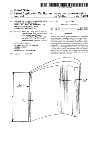
  • 5. US 2004/0115462 A1 restored simply by making the protective coating thicker during the repair procedure, in many cases. The thicknesses ofthe layer or layers ofthe protective coating are optimized to provide the necessary protection, Stability, and resistance to removal during Subsequent Service. Specifically, if the aluminide layer and/or the ceramic thermal barrier coating are made overly thick, there is a tendency for them to Spall away as a result of thermally induced Stresses and other reasons. Additionally, the protective coating does not have the same mechanical properties as the Substrate material, So that replacement of the removed substrate material with the material ofthe protective coating results in a net weakening of the article. 0012. In applications of the present approach, the metal lic coating is applied to the Substrate to build up the thickness of the Substrate, before the protective coating is applied. The metallic coating has a composition different from that of the Substrate. The metallic coating is Selected both for having good mechanical properties that are similar to those of the Substrate material, but also for its ability to be deposited in a moderately thick layer. In a typical example, the metallic coating has a thickness of at least about 0.003 inch, preferably from about 0.003 to about 0.010inch, but in Some cases as thick as 0.015 inch or more. The metallic coating restores the thickness of the Substrate back to about its original thickness, less the thickness of the protective coating, and then the optimalprotective coatingis applied over the metallic coating to restore the required overall key dimension. 0013 The metallic coating is not a diffusion aluminide protective coatingand is notan overlay aluminide protective coating. The diffusion aluminide protective coating and the overlay aluminide protective coating have a high aluminum content, typically above about 16 percent by weight. Such high-aluminum coatingsgive good oxidation protection,but they do nothave mechanical properties comparable with the Substrate material. In the case where the metallic coating is a nickel-base alloy, and preferably a nickel-base Superalloy, the aluminum content is typically less than about 10 percent by weight, and there is a high content of other elements found in Superalloys for Strength and other properties, Such as tantalum, tungsten, molybdenum, chromium, rhenium, Zirconium, titanium, niobium, boron, and/or carbon. 0.014. The aluminide layer is desirably a platinum-group metal-aluminide layer. That is, the aluminide is formed by interdiffusingan applied aluminum Sublayer with an applied Sublayer ofplatinum, palladium, or rhodium. The aluminide layer may also be formed by interdiffusing an applied aluminum Sublayer with an applied Sublayer of another element Such aschromium. The aluminide layer may instead be a simple aluminide. 0.015. A method for restoring a key dimension of and protecting an article comprises first providing an article that has previously been in Service, wherein the key dimension of the article is below a minimum permissible dimensional value. The article Serves as a Substrate having a Substrate composition. A metallic coating is deposited overlying and contacting the metallic Substrate, wherein the metallic coat ing has a metallic-coating composition different from the Substrate composition. Aprotective coating is applied over lying andcontacting the metallic coating, wherein the metal lic coating and the protective coating together have a res Jun. 17, 2004 toration thickneSS Sufficient to increase the key dimension to no less than the minimum permissible dimensional value. The protective coating comprises an aluminide layer over lying and contacting the metallic coating. Compatible fea tures discussed herein may be used with this method. 0016 Other features and advantagesofthe present inven tion will be apparent from the following more detailed description of the preferred embodiment, taken in conjunc tion with the accompanying drawings, which illustrate, by way of example, the principles of the invention. The Scope of the invention is not, however, limited to this preferred embodiment. BRIEF DESCRIPTION OF THE DRAWINGS 0017 FIG. 1 is a perspective view ofa gas turbine vane airfoil; 0018 FIG.2 is a schematicplan view ofthree gas turbine Vanes, forming two pairs of Vanes, 0019 FIG. 3 is an enlarged sectional view of one of the gas turbine vanes ofFIG.2, taken generally on line 3-3; and 0020 FIG. 4 is a block flow diagram of a preferred approach for practicing the present approach. DETAILED DESCRIPTION OF THE INVENTION 0021 FIG. 1 depicts a portion of an article 20 that is an embodiment of the present approach and may be prepared by the present approach. In this case, the article 20 is a component of a gas turbine engine, and Specifically a gas turbine vane 22 (also called a “nozzle”). The gas turbine vane 22 has the illustrated airfoil 24 and is attached to its Supportby end structure (not shown). The present approach is not limited to a turbine vane, which is the preferred application but which is presented as an example. 0022 FIG. 2 depicts three of the turbine vanes 22 arranged relative to each other as they are in a gas turbine engine. The turbine Vanes22 may be described as being two adjacent pairs of turbine Vanes. A throat Separation dimen Sion D is the distance ofclosest approach between the two vanes of each pair. The throat area TA is the product of the throat width D times the length L of the airfoil measured parallel to the lengthwise direction of the airfoil 24 (see FIG. 1). To maintain the throat area TA within its required tolerances, D must be kept within its required tolerances. DuringService, the thicknesst ofthe turbine Vanes22tends to decrease due to environmental damage, So that Do increases. However, ifD becomes too large and exceeds its maximum permitted throat Separation dimension, the opera tion and efficiency of the gas turbine engine unacceptably decreases. Thus, the thickness tv must be equal to orgreater than the minimum permissible dimensional value tvMIN. The situation wherein tv becomes less than tvMIN usually arises after the turbine Vane 22 is operated in Service, but it may arise in new-make articles are well. 0023 FIG. 3 depicts the surface region of the turbine vane 22 in greater detail. The body of the turbine vane 22 Serves as a Substrate 26 having a Substrate composition. The Substrate composition is preferably that of a nickel-base alloy Such as a nickel-base Superalloy, or a cobalt-base alloy. An “X-base' alloy is an alloy having more of element X by
  • 6. US 2004/0115462 A1 weight than any other element. A nickel-base Superalloy is a nickel-base alloy that is Strengthened by the precipitation ofgamma prime or a related phase. Acobalt-base alloy has more cobalt by weight than any other element, and a cobalt-base Superalloy typically is Strengthened by the pres ence oflarge atoms thatprovide Solid Solution Strengthening and by the precipitation of carbide phases. An example of a cobalt-base substrate composition of most interest is MAR M-509, having a nominalcomposition, in weightpercent, of about 0.6 percent carbon, about 0.1 percent manganese, about 0.4 percent Silicon, about 22.5 percent chromium, about 0.2 percent titanium, about 1.5 percent iron, about 0.01 percent boron, about 0.5 percent zirconium, about 10 percent nickel, about 7 percent tungsten, about 3.5 percent tantalum, balance cobalt and minor elements. The present approach is not limited to this alloy, which ispresented as an example. 0024. A metallic coating 28 overlies and contacts the metallic Substrate 26. The metallic coating28 has a metallic coating composition different from the Substrate composi tion. The metallic coating 28 has a composition different from that ofthe Substrate that may be readily deposited onto the Substrate 26. Most Substrate compositionssimply cannot be readily deposited as thin layerS by readily available and economically feasible deposition techniques, Such as those that may be used for the metallic-coating composition. The metallic coating 28 is metallic in nature, and is not a diffusion aluminide protective coating and is not an overlay aluminide protective coating. The diffusion aluminide pro tective coating and the overlay aluminide protective coating have a high aluminum content, typically above about 16 percentby weight. Such high-aluminum coatings give good oxidation protection, but they do not have mechanical prop ertiescomparable with the Substrate composition. In the case where the metallic coating 28 is a nickel-base alloy, and preferably a nickel-base Superalloy, the aluminum content is typically leSS than about 10 percent by weight, and there is a high content of other elements found in Superalloys for Strength and other properties, Such as tantalum, tungsten, molybdenum,chromium, rhenium, Zirconium, titanium, nio bium, boron, and/or carbon. Apreferred metallic coating28 is alloy BC-52, having a nominal composition, in weight percent, of about 18 percent chromium, about 6.5 percent aluminum, about 10 percent cobalt, about 6 percent tanta lum, about 2 percent rhenium, about 0.5 percent hafnium, about 0.3 percent yttrium, about 1 percent Silicon, about 0.015 percent zirconium, about 0.015 percent boron, about 0.06 percent carbon, the balance nickel and incidental impu rities. The present approach is not limited to this metallic coating 28, however. 0.025 A protective coating 30 overlies and contacts the metallic coating 28. The protective coating 30 includes at least an aluminide layer 32 overlying and contacting the metallic coating 28. The aluminide layer 32 is preferably a platinum-group metal-aluminide layer. The platinum-group metal aluminide comprises interdiffused aluminum and a platinum-group metal, preferably platinum, palladium, and/ or rhodium, and most preferably platinum. The aluminide layer 32 partially interdiffuses with the metallic coating 28 after exposure at elevated temperature. The aluminide layer 32 preferably has at least about 16 percent by weight aluminum and 16 percent by weight of the platinum-group metal. Jun. 17, 2004 0026. After exposure to oxygen at elevated temperature, an Outermost portion of the aluminide layer 32 oxidizes to produce an aluminum oxide (alumina) Scale 34. The alumi num oxide Scale 34 resists further oxidation, protecting the underlying Structure. For the present purposes, the alumi num oxide Scale 34 is considered part ofthe aluminide layer 32. 0027 Optionally, a ceramic thermal barrier coating 36 is part of the protective coating 30 and overlies and contacts the aluminide layer 32. The thermal barrier coating 36 is preferably Zirconia having from about 3 to about 12 percent yttria therein, a ceramic termed yttria-Stabilized Zirconia, or YSZ. 0028. The aluminide layer 32 preferably has a thickness of from about 0.0005 to about 0.004 inch thick. The ceramic thermal barrier coating 36, where present, preferably has a thickness of from about 0.005 to about 0.020 inch, more preferably from about 0.005 to about 0.015 inch. These thicknesses are Selected because of the requirement for protection of the underlying Structure, and also So that the respective thicknesses are not So great that the aluminide layer32 andceramic thermalbarriercoating36 debond from their respective underlying Structures. These thicknesses cannot be Substantially increased to replace metal lost or absent from the underlying Substrate 26. Instead, the metal lic coating 28 replaces the metal lost or absent from the Substrate 26, to bring the dimension tv back to above the minimum permissible dimensional value tvMIN. The metal lic coating 28 has strength properties generally Similar to those of the substrate 26, so that replacement of the lost metal of the Substrate 26 with the metallic coating 28 does not result in a Substantial loSS of overall Strength properties of the article 20. The materials of the protective coating 30, on the other hand, are much weaker than the material of the Substrate 26. In a typical case, the metallic coating 28 has a thickness of at least about 0.003 inch and in Some cases as high as about 0.015 inch, and usually hasa thicknessoffrom about 0.005 to about 0.010 inch. 0029 FIG. 4 depicts apreferred method ofpracticingthe invention to restore a key dimension Such astv and toprotect the article 20. The metallic article 20 or 22 that has previ ously been in service is provided, step 50. The metallic article is preferably made of a cobalt-base alloy or a nickel base alloy. The key dimension tv of the article 20 is below the minimum permissible dimensional value tvMIN.The key dimension may instead be below the minimum permissible dimensional value in a new-make article, but the situation most often arises in a repair context. The article 20 or 22 Serves as the metallic Substrate 26 having the Substrate composition. 0030 The metallic coating28 is deposited overlying and contacting the metallic Substrate 26, step 52. The metallic coating 28 has its metallic-coating composition different from the Substrate composition. In the preferred case, the BC-52 nickel-base Superalloy metallic coating is applied by any operable approach, but is preferably applied by the HVOF (high-velocity oxyfuel) process or the LPPS (low pressure-plasma spray) process, both of which are deposi tion processes that are known in the art. The HVOF process, which utilizes a high Velocity gas as a protective shield to prevent oxide formation, is a relatively low temperature thermal Spray that allows for application of a high density
  • 7. US 2004/0115462 A1 oxide-free coatingin a wide variety ofthicknesses, isknown in the art. The HVOF process typically uses any one of a variety of fuel gases, Such as Oxypropylene, oxygen/hydro gen mixtures orkerosene. Gas flow ofthe fuelcan be varied from 2000-5000 ft/sec. The temperature of the spray will depend on the combustion temperature of the fuel gas used, but will typically be in the range of3000-5000°F.The LPPS proceSS applies the coating as a plasma Spray at a reduced deposition pressure. 0031. The protective coating 30 is deposited overlying and contacting the metallic coating, Step 54. The metallic coating 28 and the protective coating 30 together have a restoration thickneSSSufficient to increase the key dimension tv to no less than the minimum permissible dimensional Value tvMIN. 0.032 To deposit the aluminide layer in the preferred form ofa platinum aluminide, a platinum-containinglayeris first deposited onto the Surface of the metallic coating 28. The platinum-containing layer is preferably deposited by electrodeposition. For the preferred platinum deposition, the deposition is accomplished by placing a platinum-contain ing Solution into a deposition tank and depositing platinum from the solution onto the surface ofthe metallic coating28. An operable platinum-containing aqueous Solution is Pt(NH),HPO, having a concentration ofabout4-20grams per liter of platinum, and the Voltage/current Source is operated at about 72-10 amperes per Square foot of facing article Surface. The platinum-containing layer, which is preferably from about 1 to about 6 micrometers thick and most preferably about 5 micrometers thick, is deposited in 1-4 hours at a temperature of 190-200 F. 0033) A layer comprising aluminum and any modifying elements is deposited over the platinum-containing layerby any operable approach, with chemical vapor deposition preferred. In that approach, a hydrogen halide activator gas, Such as hydrogen chloride, is contacted with aluminum metal or an aluminum alloy to form the corresponding aluminum halide gas. Halides of any modifyingelements are formed by the same technique. The aluminum halide (or mixture of aluminum halide and halide of the modifying element, if any) contacts the platinum-containing layer that overlies the metallic coating 28, depositing the aluminum thereon. The deposition occurs at elevated temperature Such as from about 1825 F. to about 1975 F. So that the deposited aluminum atoms interdiffuse with the platinum containing layer and Somewhat with the uppermost portion of the metallic coating 28 during a 4 to 20 hour cycle. 0034. Where used,the ceramic thermal barrier coating36 is deposited, preferably by a physical vapor deposition proceSS Such as electron beam physical vapor deposition (EBPVD). The ceramic thermal barrier coating 36 is pref erably from about 0.005 to about 0.020 inch thick. The ceramic thermal barrier coating 42 is preferably yttria stabilized zirconia (YSZ), which is zirconium oxide con taining from about 3 to about 12 weight percent, preferably from about 6 to about 8 weight percent, of yttrium oxide. Other operable ceramic materials may be used as well. Examples include yttria-Stabilized Zirconia which has been modified with additions of“third” oxides Such as lanthanum oxide, ytterbium oxide, gadolinium oxide, cerium oxide, neodymium oxide, tantalum oxide, or mixtures of these oxides, which are co-deposited with the YSZ. Jun. 17, 2004 0035. The present invention hasbeen reduced to practice. Nozzle Segments that have been previously been in Service have been repaired by the approach discussed above on a prototype-process basis. The dimension tv was initially below the Specification limit, andwasincreased to within the Specification limit by the present approach. 0036) Although a particular embodiment ofthe invention has been described in detail for purposes of illustration, various modifications and enhancements may be made with out departing from the Spirit and Scope of the invention. Accordingly, the invention is not to be limited except as by the appended claims. What is claimed is: 1. A coated article comprising: a metallic Substrate having a Substrate composition; a metallic coating overlying and contacting the metallic Substrate, wherein the metallic coating has a metallic coating composition different from the Substrate com position; and a protective coating overlying and contacting the metallic coating, wherein the protective coating comprises an aluminide layer overlying and contacting the metal lic coating. 2. The article ofclaim 1, wherein the Substrate composi tion is Selected from the group consisting of a nickel-base alloy and a cobalt-base alloy. 3. The article of claim 1, wherein the Substrate is a component of a gas turbine engine. 4. The article of claim 1, wherein the Substrate is a component of a gas turbine engine that has previously been in Service without the metallic coating thereon. 5. The article of claim 1, wherein the metallic coating is a nickel-base Superalloy. 6. The article ofclaim 1, wherein the metallic coatinghas a thickness of at least about 0.003 inch. 7. The article of claim 1, wherein the aluminide layer is a platinum-group metal-aluminide layer. 8. The article of claim 1, wherein the protective coating further comprises a ceramic thermal barrier coating overlying and contact ing the aluminide layer. 9. A coated article comprising: a metallic Substrate that is a component of a gas turbine engine and has a Substrate composition Selected from the group consisting of a nickel-base alloy and a cobalt-base alloy, wherein the Substrate is a component of a gas turbine engine that has previously been in Service without the metallic coating thereon; a metallic coating overlying and contacting the metallic Substrate, wherein the metallic coating has a metallic coating composition different from the Substrate com position; and a protective coating overlying and contacting the metallic coating, wherein the protective coating comprises a platinum-group metal-aluminide layer overlying and contacting the metallic coating. 10. The article ofclaim 9, wherein the metallic coating is a nickel-base Superalloy.
  • 8. US 2004/0115462 A1 11. The article ofclaim9,wherein the metallic coating has a thickness of at least about 0.003 inch. 12. The article of claim 9, wherein the protective coating further comprises a ceramic thermal barrier coating overlying and contact ing the aluminide layer. 13. A method for restoring a key dimension of and protecting an article, comprising the Steps of providing an article that has previously been in Service, wherein the key dimension of the article is below a minimum permissible dimensional value, and wherein the article Serves as a metallic Substrate having a Substrate composition; depositing a metallic coating overlyingand contacting the metallic Substrate, wherein the metallic coating has a metallic-coating composition different from the Sub Strate composition; depositing a protective coating overlying and contacting the metallic coating, wherein the metallic coating and the protective coatingtogether have a restoration thick neSS Sufficient to increase the key dimension to no leSS than the minimum permissible dimensional value, and wherein the protective coating comprises an aluminide layer overlying and contacting the metal lic coating. 14. The method ofclaim 13, wherein the step ofproviding the article includes the Step of Jun. 17, 2004 providing the article having the Substrate composition Selected from the group consisting of a nickel-base alloy and a cobalt-base alloy. 15.The method ofclaim 13, wherein the step ofproviding the article includes the Step of providing the article that is a component of a gas turbine engine. 16.The method ofclaim 13, wherein the step ofproviding the article includes the Step of providing the article that is a gas turbine Vane. 17. The method of claim 13, wherein the step of depos iting the metallic coating includes the Step of depositing the metallic coating that is a nickel-base Super alloy. 18. The method of claim 13, wherein the step of depos iting the metallic coating includes the Step of depositing the metallic coating having a thickness of at least about 0.003. 19. The method of claim 13, wherein the step of depos iting the protective coating includes the Step of depositing the aluminide layer asa platinum-group metal aluminide layer. 20. The method of claim 13, wherein the step of depos iting the protective coating includes the Step of depositing a ceramic thermal barrier coating overlying and contacting the aluminide layer. k k k k k