Microcontroller
•Download as PPTX, PDF•
6 likes•570 views

This presentation explains about 8051 microcontroller and the comparison between microcontroller and microprocessor. Thank you.

Recommended
More Related Content
What's hot
What's hot (20)
Similar to Microcontroller
Similar to Microcontroller (20)
More from Kshitij Wagle
Recently uploaded
Recently uploaded (20)
Microcontroller
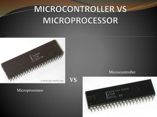
- 2. MICROPROCESSOR CPU on a chip General purpose Memory and input /output (I/O) devices should be interfaced Suitable for both big and small systems (mainframe Computers to pocket calculators) MICROCONTROLLER Computer on a chip Specific Purpose(Mainly for embedded applications) Contains on chip RAM, ROM, I/O ports, Oscillator, Serial port, etc Suitable for small systems having less I/O devices, memory, power and requiring smaller space
- 3. MICROPROCESSOR Based on Von-Neumann architecture Application Software is not ROM based. Instruction set is designed such that program and data can be transferred between CPU and RAM. Programming is generally done in Assembly Language. MICROCONTROLLER Based on Harvard architecture Application Software is ROM based. Instruction set is designed such that program and data can be transferred between CPU and ROM. Programming can be done either in Assembly or High level language.
- 4. Household Items Toys, Cameras, Video Recorders, CD players, TVs, Microwave Ovens, Washing Machines, Vacuum Cleaners, Home Security Systems, etc.
- 5. Office Equipments Fax Machines, Printers, Plotters, modems, ATM machines, smart cards, Photocopy machines, etc
- 6. Communication Cell Phones, Telephones, Pagers, Answering Machines, etc
- 7. Others Robotics, Automation , Automobile industries , etc
- 8. Intel introduced 8051, referred as MCS-51, in 1981. Due to the flexibility and versatility of 8051 family microcontrollers, they are quite popular till now. Feature/Chip 8051 8031 8052 AT89S52 ROM 4K 0K 8K Flash 4K RAM 128 bytes 128 bytes 256 bytes 128 bytes I/O Pins 32 32 32 32 Serial I/O 1 1 1 1 Timer 2 2 3 2 Interrupt Source 6 6 8 6 Large block of data is erased and written in Flash EPROM while only byte by byte erasing and writing is available in EEPROM INTRODUCTION TO MICROCONTROLLER
- 9. On-chip Oscillator On-chip RAM of limited size On-chip ROM of limited size On-chip I/O ports Built in full duplex serial port On-chip timer/counter Bus control to interface external RAM and ROM(64 kb each) Large Set of Special Purpose registers Boolean Processing Capacity (Bit addressable) Multiple Functionality of Pins Key Features of 8051 microcontrollers
- 11. PIN DESCRIPTION OF 8051 MICROCONTROLLER Port 1 Port 3 Port 0 Port 2
- 12. VCC (PIN 40) : Supply voltage (+5V) is provided to chip GND(PIN 20): Ground or Common terminal of supply XTAL1 (PIN 19) & XTAL2 (PIN 18): As discussed earlier 8051 microcontroller possess on-chip Oscillator. It can generate frequency of 1.24 MHz to 12 MHz Generally a quartz crystal of 12 MHz frequency is connected to the pins 18 and 19. The actual frequency produced is 11.0592 MHz PIN DESCRIPTION OF 8051 MICROCONTROLLER
- 13. Also two capacitors of around 30 pF are connected as shown in figure. The quartz crystal and capacitors help to produce clock pulse of exact frequency not some harmonic frequency. If a frequency source other than a crystal oscillator is used , such as a TTL Oscillator, it will be connected to XTAL1 and XTAL2 is left unconnected. PIN DESCRIPTION OF 8051 MICROCONTROLLER
- 14. RST(PIN 9): RST stands for system RESET and is active high signal.(Normally low) The Microcontroller is reset by holding RST high for at least two machine cycles and then returning it low. The execution of the program stops and begins at the first location in program memory (ROM) on reset. Need of RST circuitry oWhen the supply is just turned on. (Transient Effect) oAs backup power source.
- 15. __ EA (PIN 31): EA stands for “External Access” and is an input signal which is either connected to VCC or GND. If the program is stored in on-chip ROM then, EA is connected to VCC. If the program is stored in external ROM then, EA is connected to GND.
- 16. _____ PSEN (PIN 29): It stands for “Program Store Enable”. It is an output pin and it is connected to the OE(Output Enable) pin of the ROM. It distinguish between program memory and data Memory.
- 17. ALE (PIN 30): ALE stands for “Address Latch Enable” and is an active high output pin. Port o has got three functionality viz. I/O port, Address and Data. ALE indicates if P0 has address or data • When ALE=0, it provides data D0-D7 •When ALE=1, it has address A0-A7
- 18. PORT P0 (PIN 39 TO 32) Port P0 has got three functionalities.(I/O port, lower order address(A0 to A7) and data (D0 to D7). It can be used for input or output , each pin must be connected externally to a 10K ohm pull-up resistor. ALE indicates if P0 has address or data When ALE=0, it provides data D0-D7 When ALE=1, it has address A0-A7
- 19. PORT P1 (PIN 1 TO 8) Port P1 is simple I/O port . Internal pull up resistor is provided. PORT P2(PIN 21 TO 28) Port P2 has dual functionality.( I/o port and higher order address(A8 to A15). Port 2 must be used along with P0 to provide the 16-bit address for the external memory. Internal pull up resistor is provided.
- 20. PORT P3 (PIN 10 TO 17) Port 3 can be used as input or output. Port 3 does not need any pull-up resistors. Port 3 has the additional function of providing some extremely important signals.
- 21. There are 21 special function registers
- 25. Memory I/O PORTS Figure : Interfacing Microprocessor ALU CONTROL UNIT Microprocessor
- 26. Microcontroller