1. The purpose of this section is to provide a method for standard-
izing drawing designations for specific design requirements of
molded rubber products. Information set forth on the pages that
follow should be helpful to the design engineer in setting up real-
istic specifications for molded rubber products.
The use of proper drawing designations by designers in speci-
fying on drawings exactly what is required is a matter of para-
mount importance. Proper use of these drawing designations by
both product designer and rubber manufacturers will result in a
common understanding of the design requirements which must be
engineered into molded rubber products. To assure a uniform
method for use on drawings and in specifications, the drawing
designations on the following pages have been standardized by the
Rubber Manufacturers Association for use in the molded rubber
field.
Although rubber manufacturers can produce products to high
standards of precision, they welcome the opportunity to suggest
modifications which would reduce costs. The purchasers of mold-
ed rubber products can assist to this end by furnishing the manu-
facturers with details covering the application of their parts.
The scope of this section presents to the user the tolerances and
standards the rubber manufacturers are normally able to maintain.
These tolerances may be described as shown in this manual or by
geometric tolerancing as shown in the ASME Y14.5M standard.
Note: Where the term “Rubber” is used in this section, it is
intended to include synthetic thermosetting elastomers as well as
natural rubber. This information may also be suitable for products
made from thermoplastic elastomers.
Dimensional
Tolerances
(Tables 2-5)
Relative
Dimensions
Finish
(Table 6)
Flash Extension
(Table 7)
Bonding
(Specify Grade
and Method on
B1 and B2)
(Tables 8 & 9)
Load-Deflection
Characteristic
(Specify only
when needed)
(Table 10)
Packaging
(Table 11)
A1
A2
A3
A4
--
--
--
No designation, see
text and/or your
rubber supplier.
Specify only when
needed.
F1
F2
F3
F4
--
--
--
T.00mm T.000
T.08mm T.003
T.40mm T.016
T.80mm T.032
T1.60mm T.063
T2.35mm T.093
T∞ T∞
B1
B2
B3
B4
B5
--
--
D1
D2
D3
--
--
--
--
P1
P2
P3
--
--
--
--
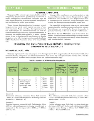
DRAWING DESIGNATIONS
The design engineer should select and designate on the drawing a separate RMA designation for each characteristic noted. Relative
dimensions, bonding, spring rate or load-deflection characteristic are to be used only when applicable. (See examples below.) If no des-
ignation is specified, the rubber manufacturer will assume that commercial tolerances apply.
Example 1:
Commercial tolerances; commercial finish; flash extension
.80mm (.032 in.) would be designated on the drawing as follows:
RMA A3-F3-T.80mm (.032 in.).
Example 2:
Precision tolerances; commercial finish; flash extension .80mm
(.032 in.) and special agreement on bonding to metal would be
designated on the drawing as follows: RMA A2-F3-T.80mm
(.032 in.) - B5.
Example 3:
Basic tolerances; commercial finish; flash extension .80mm
(.032 in.) would be designated on the drawing as follows: RMA
A4-F3-T.80mm (.032 in.).
Example 4:
Precision tolerances; good finish; flash very close; (bond sam-
ples tested to 16kN/m (90 lbs./in.) width to destruction) would be
designated on the drawing as follows: RMA A2-F2-T.40mm
(.016 in.) - B2 Grade 1 Method B.
CHAPTER 1 MOLDED RUBBER PRODUCTS
PURPOSE AND SCOPE
SUMMARY AND EXAMPLES OF RMA DRAWING DESIGNATIONS
MOLDED RUBBER PRODUCTS
Table 1 - Summary of RMA Drawing Designations
3 RMA MO-1 (2005)
2. STANDARDS FOR DIMENSIONAL TOLERANCES
RMA MO-1 (2005) 4
FACTORS AFFECTING TOLERANCES
Introduction
The purpose of this section is to list some of the factors affect-
ing tolerances. In general, the degree of reproducibility of dimen-
sions depends upon the type of tooling and rubber used, and the
state of the art.
DISCUSSION OF FACTORS AFFECTING
TOLERANCES
There are many factors involved in the manufacturing of mold-
ed rubber products which affect tolerances. Since these may be
peculiar to the rubber industry, they are listed here.
Shrinkage
Shrinkage is defined as the difference between corresponding
linear dimensions of the mold and of the molded part, both meas-
urements being made at room temperature. All rubber materials
exhibit some amount of shrinkage after molding when the part
cools. However, shrinkage of the compound is also a variable in
itself and is affected by such things as material specification, cure
time, temperature, pressure, inserts, and post cure. The mold
designer and the compounder must determine the amount of
shrinkage for the selected compound and incorporate this
allowance into the mold cavity size. Even though the mold is built
to anticipate shrinkage, there remains an inherent variability
which must be covered by adequate dimensional tolerance.
Shrinkage of rubber is a volume effect. Complex shapes in the
molded product or the presence of inserts may restrict the lineal
shrinkage in one direction and increase it in another. The skill of
the rubber manufacturer is always aimed at minimizing these vari-
ables, but they cannot be eliminated entirely.
Mold Design
Molds can be designed and built to varying degrees of preci-
sion, but not at the same cost. With any type of mold, the mold
builder must have some tolerance, and therefore, each cavity will
have some variance from the others. Dimensional tolerances on
the product must include allowances for this fact. The accuracy of
the mold register must also be considered. This is the matching of
the various plates of the mold that form the mold cavity. Register
is usually controlled by dowel pins and bushings or by self-regis-
tering cavities. For molds requiring high precision in dimensions
and register, the design work and machining must be more precise
and the cost of the molds will be greater than one with commer-
cial requirements.
Trim and Finish
The objectives of trimming and finishing operations are to
remove rubber material -- such as flash, which is not a part of the
finished product. Often this is possible without affecting important
dimensions, but in other instances, some material is removed from
the part itself. Where thin lips or projections occur at a mold part-
ing line, mechanical trimming may actually control the finished
dimension.
Inserts
Most insert materials (metal, plastic, fabric, etc.) have their
own standard tolerances. When designing inserts for molding to
rubber, other factors must be considered, such as fit in the mold
cavities, location of the inserts with respect to other dimensions,
proper hole spacing to match with mold pins, and the fact that
inserts at room temperature must fit into a heated mold. In these
matters, the rubber manufacturer can be of service in advising on
design features.
Distortion
Because rubber is a flexible material, its shape can be affected
by temperature. Distortion can occur when the part is removed
from the mold or when it is packed for shipment. This distortion
makes it difficult to measure the parts properly. Some of the dis-
tortion can be minimized by storing the part as unstressed as pos-
sible for 24 hours at room temperature. Some rubber will crystal-
ize (stiffen) when stored at low temperature and must be heated to
above room temperature to overcome this condition.
Environmental Storage Conditions
Temperature: Rubber, like other materials, changes in dimension
with changes in temperature. Compared to other materials the
coefficient of expansion of rubber is high. To have agreement in
the measurement of products that are critical or precise in dimen-
sion, it is necessary to specify a temperature at which the parts are
to be measured and the time required to stabilize the part at that
temperature.
Humidity: Some rubber materials absorb moisture. Hence the
dimensions are affected by the amount of moisture in the product.
For those products which have this property, additional tolerance
must be provided in the dimensions. The effect may be minimized
by stabilizing the product in an area of controlled humidity and
temperature for a period not less than 24 hours.
3. Dimension Terminology
The following will provide a common terminology for use in
discussing dimensions of molded rubber products, and for distin-
guishing various tolerance groupings:
Fixed Dimension: Dimensions not affected by flash thickness
variation. (Mold Closure) See Figure #1.
Closure Dimensions: Dimensions affected by flash thickness
variation. (Mold Closure) See Figure #1.
Figure 1
In addition to the shrinkage, mold maker’s tolerance, trim and
finish, a number of other factors affect closure dimensions.
Among these are flow characteristics of the raw stock, weight,
shape of preform and molding process.
While closure dimensions are affected by flash thickness vari-
ation, they are not necessarily related to basic flash thickness. If a
manufacturer plans to machine or die trim a product, the mold will
have a built-in flash, which will be thicker than if hand deflashing
or tumble trim were to be employed. Thus products purchased
from two sources could have different basic flash thickness at the
parting line and yet meet drawing dimensions.
There is usually a logical place for the mold designer to locate
the parting line for best dimensional control and part removal. If
the product design limits this location, an alternate mold construc-
tion will be required, which may affect the tolerance control on the
product, and may, in some cases, increase the cost of the mold.
Registration Dimension: Dimensions affected by the matching
of the various plates of the mold that form the mold cavity.
Register is usually controlled by dowel pins and bushings or by
self-registering cavities.
TOLERANCE TABLES
There are four levels of dimensional tolerances that are used for
molded rubber products.
“A1” High Precision
“A2” Precision
“A3” Commercial
“A4” Basic
The level selected should be based upon the need with the fol-
lowing guidelines.
“A1” is the tightest tolerance classification and indicates a
high precision rubber product. Such products require expen-
sive molds, fewer cavities per mold, costly in-process con-
trols and inspection procedures. It is desirable that the exact
method of measurement be agreed upon between rubber
manufacturer and customer, as errors in measurement may
be large in relation to the tolerance. Some materials, particu-
larly those requiring post curing, do not lend themselves to
Drawing Designation “A1” tolerances.
“A2” tolerances indicate a precision product. Molds must be
precision machined and kept in good repair. While measure-
ment methods may be simpler than the Drawing Designation
“A1”, careful inspection will usually be required.
“A3” tolerances indicate a “commercial” product and will
normally be used for most products.
“A4” tolerances apply to products where some dimensional
control is required but is secondary to cost.
When applying tolerances the following rules should be kept
in mind.
1. Fixed dimension tolerances apply individually to each
fixed dimension by its own size.
2. Closure dimension tolerances are determined by the
largest closure dimension and this single tolerance is
used for all other closure dimensions.
3. Fixed and closure dimensions for a given table do not
necessarily go together, and can be split between tables.
4. Tolerances not shown should be determined in consulta-
tion with the rubber manufacturer.
5. Care should be taken in applying standard tolerances to
products having wide sectional variations.
5 RMA MO-1 (2005)
5. Measurement of Dimensions
Conditioning of Parts: Measurements of dimensions shall be
made on parts conditioned at least 24 hours after the molding
operation. Measurements shall be completed within 60 days after
shipment or before the part is put into use, whichever is the short-
er time. Care shall be taken to ensure that the parts are not subject-
ed to adverse storage conditions.
In the case of referee measurement, particularly on Drawing
Designation “A1” tolerances or for materials known to be sensi-
tive to variations in temperature or relative humidity, the parts in
question should be conditioned for a minimum of 24 hours at 23°
± 2° C (73.4° ± 3.6° F) and at 50% ± 5% relative humidity.
Methods of Measurement: Depending upon the characteristics
of the dimension to be measured, one or more of the following
methods of measurement may be used.
(A) A coordinate measuring machine (CMM) with a stylus size
appropriate for the smallest feature or dimension to be meas-
ured.
(B) A dial micrometer with a plunger size and loading as agreed
upon by the customer and the rubber manufacturer.
(C) A suitable optical measuring device.
(D) Fixed gauges appropriate to the dimensions being meas-
ured.
(E) Other methods agreed on between customer and supplier.
Under no circumstances should the part be distorted during
measurement. On dimensions which are difficult to measure or
which have unusually close tolerances, the exact method of meas-
urement should be agreed upon in advance by the rubber manufac-
turer and the customer.
Relative Dimensions
General Information: Relative dimensions such as concentricity,
squareness, flatness, parallelism, or location of one or more inserts
in the product are dimensions described in relation to some other
dimension. Since it is impossible to foresee the many potential
designs of all molded products in which relative dimensions will
be specified, it is impractical to assign standard drawing tolerance
designations to these dimensions. The design engineer should rec-
ognize that the more precise the requirement, the more expensive
the product. He must allow the rubber manufacturer to use support
pins, lugs, chaplet pins, or ledges in the mold to provide positive
location and registration of the insert or inserts in the mold cavity.
With this in mind, it is suggested that the design engineer discuss
relative dimensional tolerances on all products directly with the
rubber manufacturer.
Other factors do affect tolerances to some minor degree. Our
attempt has been to acquaint the design engineer with background
information on the major factors which result in the need for tol-
erances on molded rubber products.
Examples of Relative Dimensions: Several examples of relative
dimensions the design engineer may be required to consider are
shown:
(A) Concentricity
(B) Squareness
(C) Flatness
(D) Parallelism
In all cases the tolerances should be considered only as a very
general guide.
CONCENTRICITY
Concentricity is the relationship of two or more circles or cir-
cular surfaces having a common center. It is designated as T.I.R.
(total indicator reading) and is the total movement of the hand of
an indicator set to record the amount that a surface varies from
being concentric.
All diameters formed in the same mold plate will be concentric
within 0.25mm TIR (.010 in. TIR).
Example:
In Fig. #2 diameter “A” will be concentric with diameter “B”
within 0.25mm TIR (.010 in. TIR)
Other diameters will be concentric within 0.75mm TIR (.030 in.
TIR).
Example:
In Fig. #2 diameter “A” or “B” will be concentric with diameter
“C” within 0.75mm TIR (.030 in. TIR).
Figure 2
RMA MO-1 (2005)7
6. Example:
Fig. #3 Outside surface will be concentric with shaft within
0.75mm TIR (.030 in. TIR) plus metal tolerance if unground.
Note: Parts may be ground to closer tolerances.
Example:
Fig. #4 Outside surface will be concentric with shaft within 2mm
TIR (.085 in. TIR) plus metal tolerance if unground.
Note: Parts may also be ground to closer tolerances.
Example:
On products similar to that described in Fig. #5 having an outside
diameter of 75mm (3 in.) concentricity within 0.75mm TIR (.030
in. TIR) and wobble within 0.75mm TIR (.030 in. TIR) can be
expected.
Note: Wobble is a term used to identify movement of a surface
that is not intended to be parallel to the TIR axis of rotation.
Figure 3
Figure 4
Figure 5
Figure 6SQUARENESS
Squareness is the quality of being at an angle of 90° such as
“surface must be square with axis”. A tolerance of 2° should be
allowed for rubber surfaces that are not ground.
Rubber Product with Metal Insert
Example:
Rubber-to-metal product in Sketch 1 Fig. #6. Rubber surface B-B
is square with axis A-A as the angle is true 90°. Sketch 2 indicates
the same example with 2° tolerances exaggerated.
Note: This type of product requires closer control than is usually
normal with commercial products.
8RMA MO-1 (2005)
7. FLATNESS
Flatness of a surface on a part is the deviation from a true plane
or straight edge.
Rubber Product (Unground).
Molded Surfaces (unground) will be flat within 0.25mm
(.010 in.).
Example:
Fig. #7 On a cup as illustrated, the bottom can be concaved or con-
vexed by no more than 0.25mm (.010 in.).
Rubber Product with Metal Insert
Surfaces that are ground after molding will be flat within
0.12mm (.005 in.). (Allowance must be made for removal of stock
during grinding operation.)
Example:
In Sketch 1 Fig. #8 after molding, deviation from the true plane
can be held to 0.25mm (.010 in.).
Example:
In Sketch 2 Fig. #8 after grinding, deviation can be held to
0.12mm (.005 in.) but dimension “H” will necessarily be affected.
Figure 7
Figure 8
PARALLELISM
Parallelism is the relationship of surfaces in different planes. To
be parallel the planes passing through the surfaces must be equi-
distant from each other at all points when measured at 90° to the
planes.
Rubber Product with Metal Inserts.
Example:
In Sketch 1 Fig. #9 the plates of the sandwich mount are parallel.
In Sketch 2 Fig. #9 they are not. On such a part approximately
200mm (8 in.) square, parallelism to within 0.75mm (.030 in.) can
be expected.
Figure 9
RMA MO-1 (2005)9
8. STANDARDS FOR MOLD CAVITY FINISH AND
MOLDED PRODUCT APPEARANCE
Introduction
The purpose of this section is to list and discuss some of the
factors that have an effect on the finish and appearance of molded
products and to present standards covering four classes of finish to
be applied to the mold cavity surface.
FACTORS AFFECTING FINISH AND
APPEARANCE
Machined Finish of Mold
The machined finish of the mold has considerable effect on the
surface finish or appearance of a rubber product.
The best finish can be obtained from a highly polished steel
mold, free from all tool marks or other imperfections. Naturally,
this type of mold is quite expensive to construct and maintain and
is not generally required unless surface finish is of paramount
importance from either an appearance or functional standpoint. In
addition, it may be desirable in some cases to chrome plate the
mold in order to maintain the required surface finish under pro-
duction conditions.
The commercial type mold is a machined steel mold made to
conform to good machine shop practice. Machine tool marks will
not ordinarily be polished out of this type mold. It should be noted
that regardless of how highly the mold itself is polished, the
appearance of the rubber surface will depend to a large extent
upon the factors outlined in the following paragraphs.
Type of Rubber Material Used
The type of rubber material used can greatly affect the appear-
ance of the rubber product. Some compounds lend themselves to
a bright glossy surface while others may be dull as molded or
become dulled very easily during handling or storage. Also, there
are some rubber compounds to which antiozonants are added to
impede attack from ozone. As these compounds age, the antiozo-
nants “bleed out”, giving the product a colored or waxy surface,
often referred to as “bloom”. This is a common practice and the
product should not be considered imperfect or defective in any
way. This or other specification requirements may make it impos-
sible to produce a product with a glossy surface.
Mold Release Used
There are certain rubber compounds that can be removed from
the mold with the use of little or no mold release lubricant, while
others require the use of a considerable quantity of mold release
lubricant. The latter may have the appearance of being oily.
If the surface of the rubber product is to be bonded to other
materials in its application or is to be painted, the designer should
designate this on the drawing so that the manufacturer may use a
mold release lubricant that will not impair adhesion quality.
Flash Removal Method
Some of the many methods used to remove flash from rubber
parts may affect the appearance of the finished product. As an
example, hand trimming will ordinarily have no effect, while tum-
bling may result in a dull surface.
Method of Designation of Finish
The symbol “F” followed by an appropriate number selected
from Table 6 shall be used to designate the type of finish required.
An arc enclosing the actual area included by this designation
and a leader to the finish number designates the type of finish
desired. The use of a finish symbol on the surface does not pre-
clude the possibility that other surfaces may require different fin-
ishes. However, the use of a standard notation is desirable wher-
ever possible to eliminate the repetition of finish symbols and
maintain simplicity. SEE FIG. #10.
Always permit “Commercial Finish” (F-3) whenever possible.
Figure 10
Drawing
Designation
F1
A smooth, polished and uniform finish completely free of tool marks, dents, nicks and scratches, as produced from a
highly polished steel mold. In areas where F1 is specified, the mold will be polished to a surface finish of 10 micro-
inches (250nm) or better.
F2
A uniform finish as produced from a polished steel mold. In areas where F2 is specified, the mold will be polished to
a surface finish of 32 micro-inches (800nm) or better but with very small tool marks not polished out.
F3
Surfaces of the mold will conform to good machine shop practice and no micro-inch finish will be specified. This is
“Commercial Finish”.
F4 Satin finish.
Table 6 - RMA Drawing Designation for Finish
10RMA MO-1 (2005)
9. STANDARDS FOR FLASH
RMA MO-1 (2005)11
Introduction
It is the purpose of this section to list and discuss many of the
factors that have an effect on the amount of flash, to describe the
basic methods by which flash can be removed, and furnish the
means by which the designer can designate on the product draw-
ing the flash location and flash variation permissible.
Definition
(A) Flash.
Flash is excess rubber on a molded product. It results from cavity
overflow and is common to most molding operations. Flash has
two dimensions -- Extension and Thickness.
(B) Flash Extension.
Flash extension is the film of rubber projecting from the part along
the parting line of the mold.
(C) Flash Thickness.
Flash thickness is measured perpendicular to the mold parting
line. Variations in flash thickness are normally included in closure
tolerances.
General Information
A method for designating permissible flash extension and
thickness on a molded product will result in better understanding
between rubber manufacturer and consumer and benefit both. This
method must permit the designation of a surface where no parting
line is permissible. It must also designate areas where a parting
line is permissible and define the amount of flash extension toler-
able in such areas. The designer, without specific rubber process-
ing knowledge, should be able to specify flash extension limits in
any given area on this drawing. Use of RMA Drawing
Designations provided in this section will provide this capability;
however, the designer should not specify how flash is to be
removed. He should specify the amount of flash extension which
can be tolerated without impairing product function or appear-
ance. A method designating areas permitting flash and describing
flash extension tolerance will result in the following benefits:
(A) Avoid errors in mold design concerning parting line loca-
tion.
(B) Uniformity in appearance and function of molded products
supplied by more than one source.
(C) Simplification of inspection procedures.
(D) Reduce over-finishing or under-finishing products.
Molding techniques have been developed to produce “flash-
less” products. The mold parting line, depending on location on
the product, is barely discernible with no measurable thickness or
extension. Initial cost and maintenance of this tooling and equip-
ment is high and very close manufacturing control is required.
In instances where flash extension is not a problem or where it
is otherwise advantageous, parts are shipped as molded with no
flash removal necessary.
Methods for removing flash from products with metal or other
inserts are approximately the same as for non-inserted rubber
products. Rubber flash adhering tightly to inserts is generally
acceptable. If it must be removed, it is done by mechanical means
such as wire brushing, abrasive belts or spot facing. If adhered
rubber flash is not permissible, it should be so specified on the
drawing.
Flash removal is an important cost factor in producing finished
molded rubber products. Cost conscious designers will permit the
widest possible latitude in flash thickness, flash extension, and in
location of flash consistent with adequate function and appearance
of the product.
FACTORS AFFECTING FLASH
Flash Location
Parting lines (flash lines) must be located to facilitate part
removal from the mold cavity after curing.
Flash Thickness
Flash thickness is determined in the molding operation and
may vary with mold design, closing pressure, with weight and
shape of preform, and type of compound used -- and many lesser
factors. Normal variations in flash thickness have been taken into
account in the tables set up for closure tolerances, and this will
receive no further consideration.
The designer should be aware that heavy or thick flash is fre-
quently designed to facilitate removal of parts from the mold and
to facilitate subsequent handling. In this regard the maximum
thickness that can be tolerated without impairing the product func-
tion or appearance should be specified.
Flash Extension
There are many methods by which flash extension on rubber
products can be removed. The particular method selected will be
determined by the degree of flash extension permitted as well as
by flash location, flash thickness, and other factors. Some of the
more common methods of flash removal are as follows:
(A) Buffing
A moving abrasive surface material is applied to the rubber part to
remove excess rubber by abrasive action.
(B) Die Trim
A cutting tool, shaped to the contour of the molded product at the
parting line, is applied with a force perpendicular to the flash
extension and against either a flat plate or a fitted shape. This cre-
ates a shearing or pinching action removing the excess flash. Die
trim can be done with a hand or machine mounted die. Machine
mounted dies are often used for multiple trimming of small uni-
formly shaped products from multi-cavity molds.
(C) Machine Trim
Flash is removed by passing the rubber part through machine
mounted rotating or reciprocating cutting tools. These devices are
customarily adapted to a particular product and may shear, saw, or
skive the flash away.
10. RMA MO-1 (2005) 12
(D) Tumble Trim
There are two basic types of tumble trimming. Both utilize a rotat-
ing barrel or drum in which the heavier rubber sections strike the
thinner and more fragile flash breaking it free. Dry tumbling at
room temperature is most effective with the higher durometer
“hard” compounds. The other type of tumbling utilizes carbon
dioxide or nitrogen to freeze the molded parts, thus making the
compound more brittle so the flash will break more readily. Any
tumbling operation will have an effect on surface finish.
(E) Mechanical Deflashing
Modern deflashing machines utilize an abrasive medium, tum-
bling, and a refrigerant for quick freezing. The time and tempera-
ture are closely controlled while the parts are agitated in an
enclosed barrel. Refrigerant (usually carbon dioxide or nitrogen)
is metered into the deflashing chamber while the parts are being
impinged with a mechanically agitated abrasive medium. The
flash, being thin, freezes first and is broken away by the abrasive
medium and the tumbling action before the heavier rubber part
itself has lost its resiliency. Some loss of surface finish may be
expected and some of the abrasive medium may adhere to the
molded parts.
(F) Pull Trim or Tear Trim
A very thin flash extension is molded immediately adjacent to the
part and a thicker flash is molded adjacent to the thin flash but far-
ther from the part. When the flash is pulled from the molded part,
it separates at its thinnest point adjacent to the molded part. This
method may result in a sawtooth or irregular appearance and it is
limited to certain compounds and product designs.
(G) Hand Trim
Flash is removed by an expedient method using hand tools such as
knives, scissors, razor blades or skiving knives.
Method of Designation of Flash
Extension
The symbol “T” with a notation in hundredths of a millimeter for
the maximum extension shall be used. Example: T .80mm.
(.80mm maximum extension permitted.) IF ENGLISH DIMEN-
SION THE DRAWING DESIGNATION WILL NOT BE FOL-
LOWED BY ANY LETTERS. EXAMPLE T .032.
Thickness
The flash thickness may be specified following the extension limit
if it is critical to the function of the part. Closure tolerances will
apply as in tables 2, 3, 4, and 5 on page 6.
Location
An arc enclosing the actual area included by this designation and
a leader to the trim symbol designates the maximum allowable
flash extension and thickness thus enclosed. If no flash can be tol-
erated in a given area, the symbol “T” .00mm is used. SEE FIG.
#11.
Standards
The designer may indicate on his drawing any amount of maxi-
mum flash extension permissible. However, as a matter of sim-
plicity, a progression of flash extension Drawing Designations is
suggested in Table 7. Only those areas requiring such a designa-
tion should be specified. The use of a standard note can frequent-
ly be used with no further notation. SEE FIG. #11.
Figure 11
Table 7 - RMA Drawing Designation for Flash Extension
Drawing
Designation
T .00mm
(T .000) No flash permitted on area designated. (Standard notation regarding other surfaces must accompany this
notation.)
T .08mm (T .003) This tolerance will normally require buffing, facing, grinding or a similar operation.
T .40mm (T .016) This tolerance will normally require precision die trimming, buffing or extremely accurate trimming.
T .80mm
(T .032) This tolerance will normally necessitate die trimming, machine trimming, tumbling, hand trimming, or tear
trimming.
T 1.60mm (T .063) This would be the normal tear trim tolerance.
T 2.35mm (T .093) This tolerance will normally require die trimming, tear trimming, or hand trimming of some type.
T ∞∞ (T ∞) No flash limitation.
11. 13 RMA MO-1 (2005)
STANDARDS FOR RUBBER-TO-METAL ADHESION
Introduction
The processes of adhering rubber to metal components are
widespread techniques in the rubber industry. Generally the same
considerations and procedures are applicable for rubber to rigid
non-metallic components, but the adhesion values may be lower.
Only the broad aspects of rubber-to-metal molding are covered
here, and more precise information can be provided by the rubber
manufacturer involved.
GENERAL INFORMATION
Application
Various adhesion levels can be obtained. For instance, to obtain
adhesion on critical products, such as engine mounts, very close
controls are required, both on metal and rubber preparation. Some
products may require only enough adhesion for assembly.
The adhesion level (tear/tensile strength) is directly affected by
type of metal, surface preparation, non-metallic inserts, compound
composition, curing conditions, and type of adhesive.
Drawings should clearly state adhesion requirements and any
other factors which can explain the degree of adhesion required
and the method of testing. A clear understanding between cus-
tomer and rubber manufacturer is essential.
Methods of Obtaining Adhesion
The method most commonly used to obtain adhesion between
rubber and metallic or non-metallic components is the use of adhe-
sive cements. Prior to the use of these special adhesives, the sur-
face of the insert must be clean and free of contamination.
The inserts may be prepared by suitable methods such as
degreasing, blasting, and/or a suitable chemical treatment. When
any one of these preparatory processes is objectionable, it should
be noted on the drawing. The rubber compound is then vulcanized
to the prepared inserts to obtain the desired adhesion.
Design Factors and Limitations
a. Avoid localized stress raising irregularities.
b. Minimize edge effects. Break, coin, or otherwise eliminate
sharp edges of all metallic members covered by the rubber.
Where fillets are not possible, extend the rubber beyond the
edges of the inserts which would otherwise terminate line to line
with the rubber.
c. Minimize surface roughness of metallic members in area
adjacent to adhered rubber.
d. Avoid welding a molded rubber component to a machine or
structure to prevent unnecessary heat deterioration. When
welding is mandatory, design metallic member as a heat sink
and provide for assembly techniques which will keep the
adhered rubber area of the metallic member below 150° C
(302° F).
Test Methods for Determining Adhesion Values
Adhesion testing is done in several ways, depending upon the
application and the product design. The methods recognized for
this testing are treated in full detail in ASTM Test Method D 429.
These methods are:
Method A. Rubber adhered between two parallel metal plates.
Method B. Ninety degree stripping test, rubber adhered to one
metal plate.
The above methods are used primarily for laboratory develop-
ment and testing production parts. These methods may be modi-
fied and applied as described under RMA Production Test
Methods section as follows.
RMA PRODUCTION TEST METHODS
Method A. Used where two metal surfaces, not necessarily paral-
lel, can be separated until the specified adhesion value is obtained
using the projected adhered area. The area to be considered should
be the projected active adhered working area of the smallest
metallic member, excluding fillets, overedge, and radii. Very
irregular areas are to be given special consideration.
Method B. Used where the rubber can be stripped from the entire
width of the part to obtain a specified adhesion value or where the
rubber can be cut in 25.4mm (1.0 in.) wide strips. Specimen rub-
ber thickness shall not exceed 9.5mm (.375 in.). In rubber sections
over 9.5mm (.375 in.), values should be negotiated between cus-
tomer and supplier.
Provide fillets in the rubber at junction line with inserts where
possible.
12. RMA MO-1 (2005) 14
Acceptance Criteria
Looseness contiguous to the adhered areas at corners, fillets,
mold parting lines, and back-rinding will ordinarily be acceptable.
The adhesion strength is usually considered to be satisfactory if
the failure causes permanent distortion of a metallic member.
If the deformation of the rubber section under test far exceeds
the functional service requirements, this factor should be taken
into consideration when establishing a reasonable adhesion value.
It is recognized that conditions for adhesion will exist where a
quantitative value cannot be obtained. In these instances, it is cus-
tomary to pull the rubber from the metallic member and examine
the nature of the failure. The acceptable degree of adhesion must
be agreed upon between the customer and the rubber manufactur-
er. Customer’s test methods and fixtures should be identical with
those of the rubber manufacturer and correlation procedures estab-
lished.
METHODS OF DESIGNATING ADHESION VALUES
The design engineer when writing specifications should use a
designation to obtain suitable adhesion for the purpose intended.
Methods of testing, such as tension pull or shear pull (RMA
Production Method “A”) or 90 degree stripping (RMA Production
Method “B”) and the minimum destruction values, as well as the
design of special testing fixtures should be specified on the draw-
ings. ASTM D2000 -- SAE J200 has two types of adhesion desig-
nations for adhesion of vulcanized rubber to metal:
1. Adhesion by vulcanization, designated by K11 or K21.
2. Adhesion by the use of cements or adhesives after vulcan-
ization, designated by K31.
This section is concerned only with K11 and K21.
Table 8 - RMA Drawing Designation for Rubber-To-Metal Adhesion Classification
Drawing
Designation
B1
(Specify method and
grade from Table 9.)
Production 100% tested to 70% of the minimum destruction values as noted in Table 9, Method A only.
In addition, sample parts tested to destruction must exceed the minimum destruction values as noted in
Table 9. (Specify Method A or Method B and Grade.)
B2
(Specify method and
grade from Table 9.)
Sample parts tested to destruction must exceed the minimum destruction values as noted in Table 9.
B3
Rubber to be adhered to metal. This designation would ordinarily be used on products where adhesion is
not critical to product function.
B4 Mechanical attachment only. Rubber is not adhered to metal.
B5 Products requiring special consideration.
As an illustration of the above drawing designation, see Example 4 in the Summary of RMA Drawing Designations on page 3.
13. 15 RMA MO-1 (2005)
Table 9 - RMA Drawing Designation for Minimum Adhesion Destruction Values
Drawing
Designation
S.I. USA Customary
Metric Units Units
Grade 1 2.8 MPa 400 psi
Grade 2
1.75 MPa For rubber compounds 250 psi
over 10.5 MPa (1500 psi)
tensile strength and 50 or
greater hardness (SHORE “A”)
1.4 MPa For rubber compounds 200 psi
under 10.5 MPa (1500 psi)
tensile strength or under 50
hardness (SHORE “A”)
Grade 3 0.35 MPa 50 psi
Drawing
Designation
S.I. USA Customary
Metric Units Units
Grade 1 16 KN/m width 90 lbs./in. width
Grade 2
9 KN/m width For rubber compounds 50 lbs./in. width
over 10.5 MPa (1500 psi)
tensile strength and 50 or
greater hardness (SHORE “A”)
7 KN/m width For rubber compounds 40 lbs./in. width
under 10.5 MPa (1500 psi)
tensile strength or under 50
hardness (SHORE “A”)
Grade 3 2.7 KN/m width 15 lbs./in. width
Method A
Method B
As an illustration of the above drawing designation, see Example 4 in Table 1 on page 3.
Table 9 is applicable only to RMA B1 and B2 levels shown in Table 8.
All grades of adhesion cannot be obtained with all compound classifications.
Grade 2 is similar to ASTM-SAE K11 and K21.
14. RMA MO-1 (2005) 16
STANDARDS FOR STATIC AND DYNAMIC LOAD
DEFLECTION CHARACTERISTICS
Introduction
Primarily, rubber is used in place of metallic, ceramic, and
other rigid materials because it will provide a greater deflection
for a given force than these other materials. Most uses of rubber
are based upon this characteristic.
In many uses of rubber, stiffness variation is not critical to the
rubber product function and in such cases the Shore A durometer
hardness specification is sufficient.
Rubber is used as an engineering material in resilient mount-
ings, vibration isolators, dampers, impact pads and many similar
applications. Where static or dynamic stiffness characteristics
become critical to the function of the product, appropriate test
specifications must be established.
METHODS AND CONSIDERATIONS
Static Methods
When a static load-deflection specification is established for a
product, in addition to a hardness requirement, the load-deflection
specification shall supercede the hardness, should be stated on the
product drawing, and agreed upon between the customer and the
rubber manufacturer. A static test is only “static” in that the load
application comes to rest before the measurement is taken or the
rate of deflection does not normally exceed 0.8mm/s (2 in./min.).
Such a test usually places the rubber in shear or compression.
There are several ways of specifying static load-deflection charac-
teristics.
a. Specify spring rate in load per unit deflection, e.g., N/m
(lb./in.) or torque per degree, e.g. N-m/deg. (lb.-in./deg.).
b. Specify a load to deflect the product within a specified
deflection range.
c. Specify a deflection resulting in a load within a specified
load range.
Dynamic Methods
Applications where rubber is used as vibration isolators are
dependent upon the behavior of the rubber under dynamic operat-
ing conditions.
Rubber is stiffer dynamically than in a static mode; and, since
the static to dynamic stiffness ratio varies with individual com-
pounds, it may be advisable to specify the dynamic characteristics
of the rubber for such applications.
When dynamic stiffness or spring rate is specified, and is criti-
cal to the rubber product performance, the complete conditions
and methods of measurement must be established between cus-
tomer and rubber manufacturer.
There are several methods of dynamic testing:
a. Steady State Resonance
b. Free Decay Resonance
c. Steady State Non-Resonant
d. Rebound Evaluation
FACTORS AFFECTING STATIC AND DYNAMIC
LOAD DEFLECTION CHARACTERISTICS
Age
The aging of rubber compounds over a period of time is a com-
plex process. The normal net effect of aging is an increase in mod-
ulus or stiffness. The magnitude of this change is dependent upon
the specific material involved and the environmental conditions.
Short term age, in the sense of the minimum number of hours
which should elapse between molding and evaluation, is also a
significant factor. Depending upon the nature of the product, the
minimum period will vary from 24 hours to 168 hours.
Dynamic History
The load-deflection characteristics of a rubber product are
affected by the work history of that specific product. The initial
loading cycle on a new part, or a part that has been in a static state
for a period of time, indicates a stiffer load-deflection characteris-
tic than do subsequent cycles. In static testing this effect becomes
stabilized and the load-deflection characteristics normally become
repeatable after two to four conditioning cycles.
In dynamic testing, the conditioning period is normally select-
ed as the time required to obtain reproducible results.
Temperature
Temperature has an effect on spring rate -- the higher the tem-
perature the lower the spring rate, and the lower the temperature
the higher the spring rate of a rubber product not under continuous
tension.
Test Conditions
The following details must be defined by the product drawing,
or referenced specification, to ensure relevant and consistent prod-
uct performance evaluation:
a. Mode of Test
1. Tension, Shear or Compression. A schematic diagram
depicting product orientation is highly desirable. The spring
rate in the compression mode is always higher than the spring
rate in the shear mode.
2. Static or Dynamic
The dynamic spring rate is always higher than the static spring
rate.
15. 17 RMA MO-1 (2005)
b. Test Level and Control Mode
1. Static testing load level or level of deformation, together
with the appropriate limits on deflection or limits of loading in
response to deformation, shall be stated.
2. Dynamic load levels shall be identified by a plus (+) value
for downward forces and a negative (-) value for upward
forces. Dynamic tests utilizing deformation control shall be
specified by double amplitude (total amplitude) values.
c. The amount and direction of preload, if required.
d. The linear or angular rate of loading or cyclic frequency.
e. The nature and number, or duration, of conditioning cycles
required prior to the test cycle or test period.
f. The ambient test temperature and the period of time the product
is held at test temperature prior to evaluation.
g. When the requirements are stated as “Spring Rate” the location
on the load-deflection chart at which the tangent is drawn, or the
load levels between which an average is taken, must be indicated.
METHODS OF DESIGNATING STATIC & DYNAMIC TOLERANCES
When applicable, the design engineer must specify load-deflection, spring rate, method of test and load-deflection tolerances. Table
10 presents standards for the three drawing designations for load-deflection tolerances. If damping, characteristics are required as a part
of a dynamic specification, commercial tolerances would be ±25% on parts up through 65 durometer hardness (SHORE A) and ±30%
for above 65 durometer hardness (SHORE A).
Table 10 - RMA Drawing Designations for Load-Deflection Tolerance
Drawing
Designation
Tolerance Range Tolerance Range
Durometer Rubber Wall Thickness Rubber Wall Thickness
Hardness 6mm (0.25 in.) or over under 6mm (0.25 in.)
D1
65 Durometer ±10% ±15% Very high precision.
Hardness (Shore A) This close tolerance
or below should only be
requested in unusual
circumstances.
Above 65 Durometer ±15% ±20%
Hardness (Shore A)
D2
65 Durometer ±11% to ±14% ±16% to ±20%
Hardness (Shore A)
or below
Precision
Above 65 Durometer ±16% to ±19% ±21% to ±26%
Hardness (Shore A)
D3
65 Durometer ±15% ±20%
Hardness (Shore A)
or below
Commercial
Above 65 Durometer ±20% ±25%
Hardness (Shore A)
16. RMA MO-1 (2005) 18
STANDARDS FOR PACKAGING
When a rubber part is packaged, it is for the sole purpose of
transportation from the supplier to the user. Packaging usually
causes some distortion of the rubber part which, if used in a rea-
sonable length of time, does not permanently affect the part.
However, when rubber parts are held in a distorted position for a
prolonged period of time, permanent set may cause permanent dis-
tortion and result in unusable parts. Any product on which distor-
tion may make the part unusable should be specified and packaged
by such methods as will prevent distortion. However, such meth-
ods are sometimes costly and should not be specified unless
absolutely necessary. When distortion is a problem, the product
should be removed from the container when received and stored
on shelves or in a manner to preserve usability. Packaging is a
complex area and should be given serious consideration. Table 11
at right is to be considered only as a guide. Special packaging
problems should be considered between purchaser and supplier.
Table 11 - Packaging
Drawing
Designation
P1
This class of product will be packaged to elimi-
nate all possible distortion during transportation
and storage. This may require special boxes, car-
tons, forms, cores, inner liners, or other special
methods.
P2
This class of product will be packaged in corru-
gated containers or boxes. The quantity of the
product packaged per container will be held to an
amount which will not crush the lower layers
from its own weight, but no forms, cores, inner
liners, etc., are necessary.
P3
This class of product will be packaged in corru-
gated paper containers, boxes, crates, burlap bags
or bundles, or on skids and pallets. This is the
most economical method of packaging but may
also produce the greatest distortion in the prod-
uct.
17. The purpose of this section is to outline in usable and easily
understood form the methods used in the manufacture of a dense
extruded rubber product, the problems that can arise from these
methods and how they affect the finished product. By presenting
this side of the process to the user he will be more adequately pre-
pared to convey to the rubber supplier his needs and requirements.
He will also be better able to understand the limits and tolerances
that can normally be expected of this type product.
It is also the purpose of this section to improve the relationship
of supplier and user through the use of common and meaningful
terms and symbols (RMA Designations). Through this better
understanding and the proper use of RMA Designations by the
user, the manufacturer should be better able to supply the needs of
the user thereby giving him better economy and satisfaction.
Certain statements and tables in this chapter have been changed
to reflect current industry practices and to agree with International
Standard ISO 3302-1:1996, Rubber -- Tolerances for products --
Part 1: Dimensional tolerances.
The information in this chapter is not intended to apply to ther-
moplastic elastomers.
PRINCIPLES OF EXTRUSION
An extruded rubber product differs from a molded rubber prod-
uct in that the rubber is forced through a die of the desired cross-
section under pressure from an extruder. The extruded product
leaves the extruder in a soft pliable unvulcanized state. The
extruded product normally must be vulcanized before it is usable.
Unvulcanized rubber compound is fed into the extruder. The
flutes of the revolving screw carry the rubber forward to the die,
building up pressure and temperature as it advances toward the
die. The rubber is forced through the die by this pressure and
swells in varying amounts depending on the type and hardness of
the compound. Due to the many variables such as temperature,
pressure, etc., the extrusion varies in size as it leaves the die, thus
requiring plus or minus tolerances on the cross-section. During the
vulcanization, the extrusion will swell or shrink in the cross-sec-
tion and length depending on the compound used. After vulcaniza-
tion, a length of extrusion has a tendency to be reduced in dimen-
sion more in the center of the length than the ends.
The extruded product is vulcanized either in a heated pressure
vessel (static vulcanization) or by the continuous vulcanization
process. A brief description of each follows:
STATIC VULCANIZATION
The extrusion is conveyed from the extrusion machine to a sta-
tion where it is cut to varying lengths depending on the finished
length and placed on a metal pan in a free state; that is, it is not
contained in a cavity as in molding. The part is then vulcanized in
a heated pressure vessel known as an autoclave. Generally the
autoclave is heated by steam which is allowed to fill the autoclave,
building up the required temperature, which then vulcanizes the
rubber into its usable form. This is known as open steam vulcan-
izing. The pressure surrounding the extrusion during open steam
curing minimizes porosity in the extrusion.
CONTINUOUS VULCANIZATION
The extrudate is fed into the vulcanization process directly
from the extruder permitting the extrusion to be vulcanized in a
continuous length. Several media are employed in the continuous
vulcanization of rubber, all of which must be operated at elevated
temperatures: air, molten salts, oils, fluidized beads, and
microwave. Microwave is a method whereby the extrudate is sub-
jected to high frequency electro magnetic waves which raises the
temperature of the extrusion to near curing state, uniformly
throughout. The lack of pressure in most continuous vulcanization
processes makes porosity in the extrusion difficult to control. For
most rubber compounds the open cure process is most practical.
A great many variables are encountered in the extrusion
process which make it necessary to require tolerances more liber-
al than molded parts. A design engineer should have a general
knowledge of the extrusion process and its variables to enable him
to design parts that can be extruded at reasonable cost.
PROCESS ILLUSTRATIONS
RUBBER EXTRUDING SYSTEMS
The systems shown below are a few variations of vulcanizing
extruded rubber.
19 RMA MO-1 (2005)
CHAPTER 2 EXTRUDED RUBBER PRODUCTS
PURPOSE AND SCOPE
18. EXTRUSION DIE
The extrusion die is a precise tool which is made by cutting an
opening through a blank of steel; the opening is shaped to form the
rubber into the desired cross-section as it is forced through the die
by the pressure from the revolving screw of the extruder. Most
rubber compounds swell and increase in dimension coming
through the die orifice. The die, by necessity, is made for a partic-
ular extruder and a particular compound.
RMA MO-1 (2005) 20
19. RMA MO-1 (2005)21
SUMMARY OF RMA DRAWING DESIGNATIONS
FOR EXTRUDED RUBBER PRODUCTS
Drawing Designations
In those cases where the design engineer can specify and accept one RMA Class on extruded products for the applicable qualifica-
tions on dimensional tolerances, ground surface, mandrel vulcanization, cut length, contour, forming, finish, T.I.R. and packaging, then
the drawing need only carry the symbol for the acceptable class as RMA Class 1-2-3 or 4 as the case may be.
Normally, however, there will be exceptions to an RMA Class. By using the following chart, these exceptions can be noted.
Table 12 - Summary of RMA Drawing Designations - Extruded Rubber Products
RMA Class
Dimensional
Tolerance*
Table 13
Finish
Table 14
Formed Tubing
Table 15
Cut Length
Tolerance*
Table 16
Angle Cut
Tolerance
Table 17
Spliced Length
Tolerance
Table 18
1
2
3
4
E1
E2
E3
--
F1
F2
F3
F4
H1
H2
H3
H4
L1
L2
L3
--
AG1
AG2
AG3
--
S1
S2
S3
--
RMA Class
Ground Surface*
Table 19
Mandrel Cured*
Table 20
T.I.R.
Table 21
Ground Tubing
Tolerance*
Table 22
Packaging
Table 23
1
2
3
4
EG1
EG2
--
--
EN1
EN2
EN3
--
K1
K2
--
--
EW1
EW2
--
--
P1
P2
P3
--
*As noted in the purpose and scope, certain statements and tables in this chapter have been changed to reflect current industry practices
and to agree with International Standard ISO 3302-1:1996, Rubber -- Tolerances for products -- Part 1: Dimensional tolerances.
Distortion
Because rubber is a flexible material affected by temperature,
distortion can occur when the part is stored or when it is packed
for shipment. This distortion makes it difficult to measure the parts
properly. Some of the distortion can be minimized by storing the
parts as unstressed as possible for 24 hours at room temperature.
Environmental Storage Conditions
Temperature
Rubber, like other materials, changes in dimension with
changes in temperature. Compared to other materials the coeffi-
cient of expansion of rubber is high. To have agreement in the
measurement of products that are critical or precise in dimension,
it is necessary to specify a temperature at which the parts are to be
measured and the time required to stabilize the part at that temper-
ature.
Humidity
Some rubber materials absorb moisture. Hence the dimensions
are affected by the amount of moisture in the product. For those
products which have this property, additional tolerance must be
provided in the dimensions. The effect may be minimized by sta-
bilizing the product in an area of controlled humidity and temper-
ature for a period not less than 24 hours.
20. RMA MO-1 (2005) 22
STANDARDS FOR CROSS SECTIONAL TOLERANCES
The following illustrations should be taken into consideration
when designing rubber parts and when describing what is needed
and expected from the manufacturer.
Extrusion Contour (Shape) Variation
Contour designates the degree of rigidity and conformity to the
cross sectional drawing. During vulcanization the tendency of the
extrusion is to sag and flatten. The degree of change in shape is
largely dependent upon the hardness or softness of the compound,
the tensile strength or quality of the compound, the thickness or
thinness of the cross sectional wall, the inner openings of the
extrusion and the rate of vulcanization. This tendency to distort
during vulcanization can best be eliminated by the use of forms or
mandrels which generally add to the cost of manufacture. This
cost can sometimes be eliminated if contour conformity is not nec-
essary to the finished extrusion. The degree of allowable collapse
or sag in a cross section should be indicated on the blueprint as
shown in illustrations below.
Figure 12
Tube may collapse as indicated by dotted line.
Figure 13
Lip may collapse as indicated by dotted line.
Squareness & Flatness of Rectangular Cross Sections
Tolerances for squareness and flatness of extruded sections are
not included in these tables. Due to the difficulty of establishing
meaningful limits to satisfy the wide area of needs, purchaser and
manufacturer should discuss and agree on these limits.
Illustration is for enlightenment only.
Figure 14
Cross Sectional Dimension Illustration.
Tolerances for illustration are
taken from Class 2, Table 13, page 23.
Figure 15
Dimension “C” in above illustration is affected by shape
variation.
Tolerances for I.D. - O.D. tubing are found in Table 13, page 23.
I.D. - O.D. Tube Tolerances
Tolerances should be established on the I.D. (or O.D.) and wall
thickness only. To include a tolerance on both I.D. and O.D. gen-
erally conflicts with the other tolerances.
Figure 16
21. 23 RMA MO-1 (2005)
STANDARDS FOR CROSS SECTIONAL TOLERANCE TABLE
The closer tolerance classes outlined below should not be specified unless required by the final application and they should be
restricted to critical dimensions. The closer tolerances demanded, the tighter the control which must be exercised during manufacture
and hence higher costs.
When particular physical properties are required in the product, it is not always possible to provide them in a combination which is
capable of fabrication to close tolerances. It is necessary, in these circumstances, that consultation take place between the customer and
supplier. In general, softer materials need greater tolerances than harder ones. Where close tolerances are required, a specific technique
of measurement should be agreed upon between purchaser and manufacturer.
Table 13
Tolerances for outside (O.D.) diameters, inside (I.D.) diameters, wall thickness, width, height, and general cross sectional dimen-
sions or extrusions...see Figures 15 and 16, Page 22.
RMA Class
1 2 3
High Precision Precision Commercial
Drawing Designation E1 E2 E3
Dimensions (in Millimeters)
Above Up to
0 1.5
1.5 2.5
2.5 4.0
4.0 6.3
6.3 10.0
10.0 16.0
16.0 25.0
25.0 40.0
40.0 63.0
63.0 100.0
±0.15 ±0.25 ±0.40
0.20 0.35 0.50
0.25 0.40 0.70
0.35 0.50 0.80
0.40 0.70 1.00
0.50 0.80 1.30
0.70 1.00 1.60
0.80 1.30 2.00
1.00 1.60 2.50
1.30 2.00 3.20
RMA Class
1 2 3
High Precision Precision Commercial
Drawing Designation E1 E2 E3
Dimensions (in Inches)
Above Up to
0.00 0.06
0.06 0.10
0.10 0.16
0.16 0.25
0.25 0.39
0.39 0.63
0.63 0.98
0.98 1.57
1.57 2.48
2.48 3.94
±0.006 ±0.010 ±0.015
0.008 0.014 0.020
0.010 0.016 0.027
0.014 0.020 0.031
0.016 0.027 0.039
0.020 0.031 0.051
0.027 0.039 0.063
0.031 0.051 0.079
0.039 0.063 0.098
0.051 0.079 0.126
Note: Tolerances on dimensions above 100mm (3.94 in.) should be agreed on by supplier and user. General cross sectional dimen-
sions below 1mm (0.04 in.) are impractical.
In general, softer materials and those requiring a post cure need greater tolerances.
22. RMA MO-1 (2005) 24
STANDARDS FOR EXTRUDED FINISH AND APPEARANCE
In the process of producing extruded parts, it is necessary to use
various lubricants, release agents, dusting agents, and other solu-
tions. It may be necessary to remove these materials from the
extrusion after vulcanization because of an appearance require-
ment. The cost of cleaning may be eliminated from those products
which are concealed or do not hinder assembly. The purchaser’s
intent and desire in this area should be conveyed to the rubber
manufacturer by use of the proper RMA class of finish designa-
tion. Full consideration of finish requirements may result in con-
siderable cost savings on the product.
Table 14 - Drawing Designation for Extrusion Finish
RMA
Class
Drawing
Designation
1 F1
Product shall have surface finish
smooth, clean and free from any for-
eign matter.
2 F2
Product shall have surface finish
cleaned of dust and foreign matter
but slight streaks or spots accept-
able.
3 F3
Product shall have loose dust and
foreign matter removed but natural
finish (not washed) acceptable.
4 F4
Product shall be acceptable with no
cleaning necessary. Dust or solution
deposits acceptable. Coarse or
grainy surface acceptable.
STANDARDS FOR FORMED TUBING (FOR SPECIAL SHAPES)
The type of product discussed in this section is formed by forc-
ing unvulcanized tubing over a mandrel or flexible core bent to the
required radii or shape.
In forcing the unvulcanized tubing over the mandrel or flexible
core and around a bend, the wall thickness will be stretched on the
outside of the bend and compressed on the inside of the bend. If
the bend or radius is too severe, folds or wrinkles will form on the
inside of the bend and severe stretching will occur on the outside
of the bend.
The minimum bending radius at which tubing may be formed
will depend upon the outside diameter and wall thickness and
should never be less than 150% of the outside diameter (O.D.).
If a small radius or a specific angle is required, the part should
be molded. This is necessary because, in addition to folds and
wrinkles on the inside of the radius, it may be impossible to force
the tubing over the bend or to strip it from the mandrel during the
manufacturing process.
If a minimum wall thickness is specified, it will mean this min-
imum thickness must be furnished at the outside bend or stretched
section, and depending on the severity of the bend or bends, it will
require an oversize wall thickness on the rest of the tubing from
0.40mm (0.016 in.) to 0.80mm (0.032 in.) to ensure the minimum
thickness on the stretched area. If tubing is specified, it must be
understood that, depending on the severity of the bend or bends,
wall thickness will be from 0.40mm (0.016 in.) to 0.80mm (0.032
in.) undersize in the stretched areas.
Figure 17
Figure 18
Figure 19
EXAMPLE OF RADIUS, STRAIGHT END, FLARED END,
WRINKLES, BUCKLES AND WALL THICKNESS. MINI-
MUM BEND RADIUS.
23. 25 RMA MO-1 (2005)
The leading end of the tubing will stretch and enlarge as it is
forced over the mandrel or flexible core, according to the severity
of the bend or bends, and will not fully recover to original size
during vulcanization. If both ends of the formed tubing must meet
specification set forth for the original cross section, the product
should either be molded or the lead end should be designed to fit
a 1.6mm (0.063 in.) oversize fixture. If the straight section adja-
cent to any sharp bend is to be shorter than 300% of the O.D. of
the tube, it must be understood that the tube must be made long
enough to eliminate the flare and cut back to desired length after
removal from mandrel. When forming tubing all bends and radii
must be approximate, as natural spring-back of tubing formed
under tension precludes the possibility of holding to an exact
radius or shape. The tubing being flexible will adjust itself on
assembly to compensate for these small variations. Measurement
from beginning of bends or radii to other bends and radii are also
approximate and subject to small variations for the same reasons.
Where expanded ends are required, the inside and outside of
the tubing should blend from the regular cross section to the
expanded cross section and not with a definite contour and radius
as formed on a molded part. The walls of the enlarged section will
be thinner than the regular section by 0.40mm (0.016 in.) to
0.80mm (0.032 in.), depending on the severity of enlargement.
Expansion beyond 100% of I.D. of tubing is not practical. Any
requirements beyond 100% must be molded.
Table 15 - Drawing Designation for Formed Tubing
RMA
Class
Drawing
Designation
1 H1
Product to be furnished to minimum
wall thickness specified and main-
tained throughout. Ends to be
trimmed true and even.
2 H2
Product to be furnished to general
cross section with stretched or thin-
ner wall acceptable at bends or radii.
Otherwise, same as Class 1.
3 H3
Product may be furnished partially
out of round in straight or bent sec-
tions. Ends may not necessarily be
straight and true. Minor flat spots
permissible.
4 H4
Product may be furnished partially
out of round in straight or bent sec-
tions. Flat spots and slight wrinkles
or buckles permissible. Product may
be cut to length in unvulcanized
state. (Allow 12.3mm (.500 in.) for
every 750mm (30 in.) of length.)
Special tolerance to be established
between supplier and purchaser.
24. RMA MO-1 (2005) 26
STANDARDS FOR CUT LENGTH TOLERANCES FOR UNSPLICED EXTRUSIONS
Unspliced extrusions are classified as those that generally require only extruding, vulcanizing and cutting to length. They are of var-
ious cross sectional designs and do not include lathe cut parts, formed tubing, or precision ground and cut parts. They are generally
packed in a straight or coiled condition after being measured and cut to length.
The following tables are to be used to convey to the manufacturer the limits that are desired by the purchaser.
It should be understood by the design engineers that due to the stretch factor in rubber, a period of conditioning at room tempera-
ture must be allowed before measurements for length are taken. Accurate measurement of long lengths is difficult because they stretch
or compress easily. Where close tolerances are required on long lengths, a specific technique of measurement should be agreed upon
between purchaser and manufacturer.
Table 16 - Cut Length Tolerance Table for Unspliced Extrusion
RMA Class
1 2 3
(Precision) (Commercial) (Non-Critical)
Drawing Designation L1 L2 L3
Length (in Millimeters)
Above Up to
0 40
40 63
63 100
100 160
160 250
250 400
400 630
630 1000
1000 1600
1600 2500
2500 4000
4000
±0.7 ±1.0 ±1.6
0.8 1.3 2.0
1.0 1.6 2.5
1.3 2.0 3.2
1.6 2.5 4.0
2.0 3.2 5.0
2.5 4.0 6.3
3.2 5.0 10.0
4.0 6.3 12.5
5.0 10.0 16.0
6.3 12.5 20.0
0.16% 0.32% 0.50%
Length (in Inches)
Above Up to
0 1.6
1.6 2.5
2.5 4.0
4.0 6.3
6.3 10.0
10.0 16.0
16.0 25.0
25.0 40.0
40.0 63.0
63.0 100.0
100.0 160.0
160.0
±0.03 ±0.04 ±0.06
0.03 0.05 0.08
0.04 0.06 0.10
0.05 0.08 0.13
0.06 0.10 0.16
0.08 0.13 0.20
0.10 0.16 0.25
0.13 0.20 0.40
0.16 0.25 0.50
0.20 0.40 0.63
0.25 0.50 0.80
0.16% 0.32% 0.50%
Note: Special consideration on tolerances will have to be given to both extremely soft and high tensile stocks.
25. 27 RMA MO-1 (2005)
STANDARDS FOR ANGLE CUT TOLERANCES FOR EXTRUSIONS
Many methods are employed to cut extruded sections to length:
circular knife, rotating knife, guillotine, shear, saw and hand knife.
The angle and curve on cut face of extrusion will differ in
degree depending upon the method used to cut the extrusion as
well as the hardness of the compound, design or cross section and
thickness of the extrusion.
(The force of the knife upon the extrusion at the line of pene-
tration deforms the extrusion resulting in a curved surface and an
angle cut.)
Table 17
Angle (AG) Tolerances
RMA Class
Drawing
Designation
Cut (Max)
Precision AG1 4°
Commercial AG2 6°
Non-Critical AG3 10°
Figure 20
26. RMA MO-1 (2005) 28
STANDARDS FOR SPLICED EXTRUSIONS
Testing Procedure
The manufacture of extrusions in circular or rectangular shaped
gaskets, or a combination of both, can be accomplished by means
of butt or corner vulcanized splices. The splice is usually never as
strong as the original material from which the gasket is made. The
stronger the splice is required to be, the more difficult the labor
operations. A pressure mark will appear at the splice area due to
required holding pressure in the mold. Glass and metal channels
will be open at the corners 50mm (2 in.) to 75mm (3 in.) from the
corner as a result of the forming plates of the mold. These will
generally be open from 50% to 75% of the base of the channel.
(See Figure 21.)
Figure 21
The method of testing splices should be given serious consid-
eration. The doubling over, pinching and the twisting of a splice or
bending back on a corner splice are not proper methods of testing.
Because of the wide variety in the types of cross sections, splice
strength is very difficult to define.
Splice strength varies due to configuration of the cross section.
Transfer and injection splices are stronger than butt splice joints.
Pulling perpendicular to the plane of the splice is a sufficient
test in the testing of a corner splice. The gasket should be clamped
in such a way that the pull is evenly distributed over the splice and
not have most of the stress on the inside corner. For injection
splice, see Figure 22 and for 45° corner splice, see Figure 23.
Table 18 - Spliced Length Tolerances
RMA Class
1 2 3
Precision Commercial Non-Critical
Drawing
Designations
S1 S2 S3
Millimeters
Above - Up to
0 - 250
250 - 400
400 - 630
630 - 1000
1000 - 1600
1600 - 2500
2500 - over
±3.2 ±6.3 ±7.1
4.0 7.1 8.0
5.0 8.0 9.0
6.3 9.0 10.0
8.0 10.0 11.2
10.0 11.2 12.3
12.5 12.5 16.0
Inches
Above - Up to
0 - 10
10 - 16
16 - 25
25 - 40
40 - 63
63 - 100
100 - over
±.13 ±.25 ±.28
.16 .28 .32
.20 .32 .36
.25 .36 .40
.32 .40 .45
.40 .45 .50
.50 .50 .53
In some applications, the splice is required only to position a
gasket into place in assembly. This can be accomplished by staples
or by using room temperature vulcanizing cements. These are
more economical than vulcanized splices.
Tolerances must be allowed in the length of spliced parts.
These tolerances must be varied according to length between
splices and due to the method of making the splice. The following
tables show classes which include both conventional splice
requirements and injection splice requirements. Class 1 and 2 are
acceptable for conventional splices and Class 2 and 3 are accept-
able for injection splices. Discussion between manufacturer and
customer should determine the class acceptable and the method of
manufacture most acceptable.
Figure 22
Figure 23
Figure 24
Figure 25
Open as indicated
by Dotted Lines
Pull test in Direction of
Arrows. Pull rate of
500mm/min. (20 in./min.)
is generally acceptable.
Pull test for 45° corners.
Pull in direction of arrow.
Tolerance on Illustration are Class 2.
27. 29 RMA MO-1 (2005)
DESIGN OF EXTRUDED ENDLESS SPLICES
When designing endless splices for extruded profiles, several
factors must be considered: durometer of compound, cut length,
size of cross section and in the case of tubing, wall thickness.
Mold cavities are normally designed to the nominal dimension.
If the extrudate cross section is at the top of the extruded toler-
ance, mold pressure marks will be visible on the surface and more
so with the use of lower durometer compounds. If the extrudate
cross section is at the low end of the extruded tolerance, the mold
cavity would have to be shimmed in order to attain splicing pres-
sure creating some surface marking. The longer the cut length, the
greater the difference in size at each end. (One end may be on high
tolerance and the other end on low tolerance.) Generally, this gives
the appearance of a step or mismatch. See Figure 26.
Tubing is subject to the same considerations but in addition,
thin wall tubing may require internal support in order to achieve
sufficient molding pressure. The type of insert used and whether
or not it should be removed would have to be resolved between
manufacturer and purchaser.
It is to the advantage of both customer and rubber manufactur-
er to discuss design and application of extruded endless splices.
See Figure 27.
Figure 26
Figure 27
28. RMA MO-1 (2005) 30
STANDARDS FOR OUTSIDE DIMENSIONS OF SURFACE GROUND EXTRUSIONS
If it becomes necessary to hold the outside diameter of extruded mandrel cured tubing to closer tolerances than normal manufactur-
ing methods will permit, this can be accomplished by surface grinding the part if the part has an inside diameter of 5.0mm (0.20 in.) or
more.
A drawing of this type of part should specify inside diameter or outside diameter, wall thickness, and outside finish. If ground fin-
ish is desired, it should be classified as one of the following : rough, smooth, or fine.
Table 19 - Tolerances on Outside Dimensions of Surface-Ground Extrusions
RMA Class
1 2
(Precision) (Commercial)
Drawing Designation EG1 EG2
Dimensions (In Millimeters)
Above Up to
5 10
10 16
16 25
25 40
40 63
63 100
100 160
160
±0.15 ±0.25
0.20 0.35
0.20 0.40
0.25 0.50
0.35 0.70
0.40 0.80
0.50 1.00
0.3% 0.6%
Dimensions (In Inches)
Above Up to
0.20 0.40
0.40 0.63
0.63 1.00
1.00 1.60
1.60 2.50
2.50 4.00
4.00 6.30
6.30
±0.006 ±0.010
0.008 0.014
0.008 0.016
0.010 0.020
0.014 0.028
0.016 0.032
0.020 0.040
0.3% 0.6%
29. 31 RMA MO-1 (2005)
STANDARDS FOR INTERNAL DIMENSIONS
OF MANDREL-SUPPORTED EXTRUSIONS
When it becomes necessary to hold the tubing round and to close tolerances, a mandrel of the proper size must be inserted in the I.D.
of the tubing before vulcanizing. This limits the length of the tubes. Shrinkage usually occurs when the product is removed from the
mandrel so that the resulting size of the mandrel-supported dimension is smaller than the mandrel size. The dimension may, however,
be larger should the positive tolerance for the mandrel exceed the shrinkage of the extrudate and in this case both positive and negative
tolerances will need to be applied.
The designer should indicate what type of surface would be required on the O.D. of the tubing such as ground surface, cloth wrapped
surface or as extruded. Any tube that has to have close tolerances on the O.D. generally will have a ground finish. A cloth wrap is used
usually to help maintain a round I.D. and O.D. when the stock is soft and may sag in curing. The cloth wrapping of a tube (the tube is
placed on a mandrel and wrapped tightly in cloth before vulcanizing and then removed after vulcanizing) leaves the imprint of the cloth
weave in the rubber.
If type of surface is not indicated, it would then be assumed that the surface is to be as extruded.
Table 20 - Tolerances on Internal Dimensions of Mandrel-Supported Extrusions
RMA Class
1 2 3
(Precision) (Commercial) (Non-Critical)
Drawing Designation EN1 EN2 EN3
Dimensions (in Millimeters)
Above Up to
0 4
4 6.3
6.3 10
10 16
16 25
25 40
40 63
63 100
100 160
160
±0.20 ±0.20 ±0.35
0.20 0.25 0.40
0.25 0.35 0.50
0.35 0.40 0.70
0.40 0.50 0.80
0.50 0.70 1.00
0.70 0.80 1.30
0.80 1.00 1.60
1.00 1.30 2.00
0.6% 0.8% 1.2%
Dimensions (in Inches)
Above Up to
0 0.16
0.16 0.25
0.25 0.40
0.40 0.63
0.63 1.00
1.00 1.60
1.60 2.50
2.50 4.00
4.00 6.30
6.30
±0.008 ±0.008 ±0.014
0.008 0.010 0.016
0.010 0.014 0.020
0.014 0.016 0.028
0.016 0.020 0.032
0.020 0.028 0.040
0.028 0.032 0.051
0.032 0.040 0.063
0.040 0.051 0.079
0.6% 0.8% 1.2%
30. RMA MO-1 (2005) 32
STANDARD FOR CONCENTRICITY OF MANDREL CURED
AND GROUND EXTRUDED TUBING
CONCENTRICITY
Concentricity is the relationship of two or more circles or circular surfaces having a common center. It is usually designated as T.I.R.
(Total Indicator Reading) and is the total movement of the hand of an indicator set to record the amount that a surface varies from being
concentric.
Table 21 - T.I.R. Tolerances
RMA Class
1 2
(Precision) (Commercial)
Drawing Designation K1 K2
O.D. (In Millimeters)
Above Up to
0 13
13 20
20 32
32 50
50 80
80 Over
0.20 0.40
0.25 0.50
0.33 0.75
0.47 1.15
0.50 1.65
0.64 2.30
O.D. (In Inches)
Above Up to
0.0 0.5
0.5 0.8
0.8 1.25
1.25 2.00
2.00 3.15
3.15 Over
0.008 0.015
0.010 0.020
0.013 0.030
0.016 0.045
0.020 0.065
0.025 0.090
When the above specimen is rotated 360° about the center of the inside circle with a dial indicator in contact with the outside circle,
the total sweep of the indicator hand or difference to right and left of zero in above example is referred to as “Total Indicator Reading”
or T.I.R. The T.I.R. in this example is 20 units.
31. 33 RMA MO-1 (2005)
OPTIONAL METHOD OF TOLERANCING GROUND EXTRUDED TUBING
Table 22 - Tolerances on Wall Thickness of Surface-Ground Extrusions
RMA Class
1 2
(Precision) (Commercial)
Drawing Designation EW1 EW2
Nominal Dimension (In Millimeters)
Above Up to
0.0 4.0
4.0 6.3
6.3 10.0
10.0 16.0
16.0 25.0
±0.10 ±0.20
0.15 0.20
0.20 0.25
0.20 0.35
0.25 0.40
Nominal Dimension (In Inches)
Above Up to
0.0 0.16
0.16 0.25
0.25 0.40
0.40 0.63
0.63 1.00
±0.004 ±0.008
0.006 0.008
0.008 0.010
0.008 0.014
0.010 0.016
32. RMA MO-1 (2005) 34
STANDARDS FOR PACKAGING
When a rubber part is packaged, it is for the sole purpose of
transportation from the supplier to the user. Packaging usually
causes some distortion of the rubber part which, if used in a rea-
sonable length of time, does not permanently affect the part.
However, when rubber parts are held in a distorted position for a
prolonged period of time, permanent set may cause permanent dis-
tortion and result in unusable parts. Any product on which distor-
tion may make the part unusable should be specified and packaged
by such methods as will prevent distortion. However, such meth-
ods are expensive and should not be specified unless absolutely
necessary. With extrusions in long lengths, where it is impractical
to ship in straight lengths and coiling in boxes or cartons causes
distortion of the product, the product should be removed from the
container when received and stored in straight lengths on shelves
to preserve usability. Packaging is a complex area and should be
given serious consideration. The table at right is to be considered
only as a guide. Special packaging problems should be considered
between purchaser and supplier.
RMA
Class
Drawing
Designation
1 P1
This class of product will be pack-
aged to eliminate all possible distor-
tion during transportation and stor-
age. This may require special boxes,
cartons, forms, cores, inner liners, or
other special methods.
2 P2
This class of product will be pack-
aged in corrugated containers or
boxes. The quantity of the product
packaged per container will be held
to an amount which will not crush
the lower layers from its own
weight, but no forms, cores, inner
liners, etc. are necessary.
3 P3
This class of product will be pack-
aged in corrugated paper containers,
boxes, crates, burlap bags or bun-
dles, or on skids and pallets. This is
the most economical method of
packaging but may also produce the
greatest distortion in the product.
Table 23 - Extrusion Packaging
33. CHAPTER 3 LATHE CUT RUBBER PRODUCTS
35 RMA MO-1 (2005)
PURPOSE AND SCOPE
The purpose of this section is to provide the design engineer
with sufficient information concerning the lathe cut manufactur-
ing process that will permit him to select the design parameters for
lathe cut products which will meet his needs. In addition, this sec-
tion will outline the methods of specifying a lathe cut product and
the tolerance capability that is available through current manufac-
turing processes.
What is a Lathe Cut?
A lathe cut product is manufactured from a cylindrical tube of
rubber by inserting a mandrel into the cylindrical tube and cutting
the finished dimensions with a knife while the mandrel is being
turned at high speed in a lathe type machine.
Method of Manufacture
The cylindrical tube from which lathe cut products are cut
made may be produced by several manufacturing processes
depending on design parameters such as size, quantity required,
tolerances, and material. The most common manufacturing
processes used to produce this tube are:
a. Injection or compression molding - Since the tube is formed by
the molding process, the inside diameter and wall thickness (or
outside diameter) are determined by the mold dimensions.
Depending on the mold construction, there may be a parting line
on the part outside diameter.
b. Extrusion with continuous vulcanization - Usually suitable for
higher volume products. The inside diameter and wall thickness
(or outside diameter) should be at finished dimensions after the
vulcanization process.
c. Extrusion with steam cure vulcanization - The extruded tube is
loaded onto a curing mandrel and placed in an open steam auto-
clave. This process may require the tube to be wrapped tight with
a fabric material prior to vulcanization to keep the inside diameter
in contact with the mandrel. The vulcanization process and man-
drel size determines the finished inside diameter dimension. Once
the tube is vulcanized, the outside diameter must be ground to pro-
vide the proper wall or outside diameter dimension. This is
accomplished by placing a mandrel inside the cylindrical tube and
grinding the outside diameter to the specified size.
Uses
Lathe cut products are used in many applications such as:
Seals, Drive Belts, Vibration Dampeners, Bumpers, Bushings and
Insulators.
Design Configurations
Various cross sections are available for lathe cut parts as shown
below. (Consult supplier for design specifications.)
Figure 28
Tube Cylindrical
Cut
Standard
Square Cut
Gasket
Cut
Single OD
Bevel Cut
Double OD
Bevel Cut
Single side
Bevel Cut
Double Side
Bevel cut
OD V-Groove
Cut
SPECIAL ANGLE CUTS
HOW TO SPECIFY A LATHE CUT PRODUCT
Because of the manufacturing methods (as described) required
to produce a lathe cut part, it is very important for the design engi-
neer to consider what are the most critical dimensions of the lathe
cut part with respect to its application. The conventional lathe cut
part with the cut 90° from the axis of the tube can be specified in
one of the three following manners:
(1) Normal or most common method--If the inside diameter is the
most critical dimension to the function of the part, the lathe cut
product will be specified by inside diameter ± tolerance, the wall
thickness ± tolerance, and cut thickness ± tolerance. The toler-
ances will be selected from Table 24.
(2) If the outside diameter is the most critical dimension to the
function of the part, the lathe cut product will be dimensioned by
outside diameter ± tolerance as measured over a fixed diameter
mandrel that provides a minimum of 3% stretch and the cut thick-
ness ± tolerance. The outside diameter tolerance for lathe cut parts
specified by this method will be selected from Table 25. The cut
tolerance will be selected from Table 24.
(3) If the lathe cut product is intended to replace an o-ring, a
square cut seal should be specified. The lathe cut product will be
specified by inside diameter ± tolerance, the wall dimension ± tol-
erance and the cut dimension ± tolerance. The nominal wall
dimensions and cut dimensions should be equal. Refer to the sec-
tion “Lathe Cut Products Used as Seals”, p. 39.
(4) If concentricity is critical to the function of the part, the toler-
ance will be selected from Table 26.
36. RMA MO-1 (2005) 38
Drawing Designation C1 C2 C3
RMA Class Precision Commercial Non-Critical
Wall Thickness (mm)
Above Included
.76 5.08
5.08 7.62
7.62 & over
±.13 ±.20 ±.38
.20 .30 .51
.25 .38 .64
Wall Thickness (in.)
Above Included
.030 .200
.200 .300
.300 & over
±.005 ±.008 ±.015
.008 .012 .020
.010 .015 .025
Table 25 - O.D. Tolerance (Measured on Fixed Mandrel)
Note: This chart is to be used only when outside diameter is the most critical dimension. The specification should be outside diame-
ter ± tolerance from the above chart when measured over a fixed diameter mandrel.
Example for C1
O.D. to measure 101.6 ± .20
(4.000 ± .008)
dia. when measured over an 89.90 diameter mandrel.
(3.5000)
Table 26 - Standards for Total Indicator Reading (T.I.R.) Tolerance (Concentricity*)
Drawing Designation C1 C2
RMA Class Precision Commercial
Inside Diameter (I.D.) (mm)
Above Included
---- 12.70
12.70 25.40
25.40 50.80
50.80 & over
.20 .20
.20 .25
.20 .33
.20 .41
Inside Diameter (I.D.) (in.)
Above Included
---- .500
.500 1.000
1.000 2.000
2.000 & over
.008 .008
.008 .010
.008 .013
.008 .016
*Concentricity is the relationship of two or more circles or circular surfaces having a common center. It is usually designated as
T.I.R. (total indicator reading) and is the total movement of the hand of an indicator set to record the amount that a surface varies
from being concentric. (See example on page 32)
37. 39 RMA MO-1 (2005)
LATHE CUT PRODUCTS USED AS SEALS
When selecting a lathe cut product to fit an existing gland or
when designing a seal gland in a new application, the relationship
of the lathe cut seal cross section to the gland depth and width is
of prime importance. The gland depth governs the amount of
squeeze applied to the seal section, while the gland width affects
the way the seal fills the gland.
Nearly all applications of lathe cut seals fall into one of the four
configurations shown below:
The design chart, Table 27, provides suggested gland depths
and widths for each of the five standard seal cross sections. The
five standard cross sections are equivalent to the five standard
cross sections for O-rings as specified in AS 568 A. Slight varia-
tions in existing seal glands from the dimensions shown here are
not uncommon. A variation of a few thousandths of an inch in an
existing gland does not prevent the selection and application of a
standard cross section seal.
Seal squeeze is radial for applications assembled on a rod (A)
or in a bore (B). The gland is cut on the outside diameter of a pis-
ton or the inside diameter of a bore. Squeeze is obtained when the
two mating surfaces are assembled.
For face seal application the gland is cut in the face of a flange
or cover. Here consideration should be given to the direction of
applied pressure. The seal should be sized to make contact with
the low pressure side of the groove as installed. For internal pres-
sure, the seal makes contact with the outside diameter of the gland
(C). Conversely, for external pressure applications, the seal is
selected to make contact with the inside diameter of the gland (D).
The design chart, Table 27, may be used as a guide in the
design of special seals and glands. Particular attention should be
given to seal squeeze and gland fill. The chart states the suggest-
ed amount of squeeze on the seal cross section necessary to ensure
reliable seal performance without overstressing the seal material.
Squeeze is added to the gland depth to determine the seal wall
dimensions for radial applications. For face seal application,
squeeze is added to the gland depth to determine the seal’s cut
thickness. (See Figure 31)
Next, consider the percent of fill which is the ratio of the cross
sectional area of the seal to the cross sectional area of the gland.
In most applications, the designed percent of fill is 80%. This pro-
vides ample space for the seal under applied squeeze and allows
space for seal swell due to fluid and temperature effects. High
pressure applications above 1500 psi, however, may require a
greater percent of fill.
Starting with the one seal cross sectional dimension determined
by squeeze, the other seal dimension can be determined to arrive
at the desired percent of gland fill.
Inside diameter of the seal is determined by the diameter of the
gland. For applications where the seal is assembled on a rod or as
an external face seal, the inside diameter should make contact with
the groove. When assembled in a bore or as an internal face seal,
the outside diameter of the seal should make contact with the
groove. In both cases, this is prior to assembly.
Figure 30 - Four basic applications
38. AS 568 A
Dash No.
Nom.
Cross
Section
Actual Cross
Section
W x TK
Gland
Depth
Gland
Width
Inside
Radius
Max.
Clearance
Gap
Max.
Squeeze
Min. Mean Max.
Dimensions in mm
+.00
-.05
+.13
-.13
000 - 050
106 - 178
201 - 284
309 - 387
425 - 465
1.59
2.38
3.18
4.76
6.35
1.68 x 1.68
2.51 x 2.51
3.40 x 3.40
5.16 x 5.16
6.73 x 6.73
1.44
2.29
3.11
4.75
6.10
2.51
3.71
4.90
7.19
9.65
.38
.38
.64
.76
.76
.05
.06
.08
.09
.13
.13
.13
.19
.28
.51
.25
.25
.32
.43
.66
.38
.38
.44
.58
.08
Dimensions in in.
+.000
-.002
+.005
-.005
000 - 050
106 - 170
201 - 284
309 - 387
425 - 465
1/16”
3/32”
1/8”
3/16”
1/4”
.066 x .066
.099 x .099
.134 x .134
.203 x .203
.265 x .265
.057
.090
.1225
.187
.240
.099
.146
.193
.286
.380
.015
.015
.025
.030
.030
.002
.0025
.003
.0035
.005
.005
.005
.0075
.011
.020
.010
.010
.0125
.017
.026
.015
.015
.0175
.023
.032
RMA MO-1 (2005) 40
Table 27 - Design Chart
Figure 31
39. CHAPTER 4 CELLULAR RUBBER PRODUCTS
SPONGE AND EXPANDED * SHEET * MOLDED AND EXTRUDED
PURPOSE AND SCOPE
41 RMA MO-1 (2005)
The purpose of this chapter is to acquaint the design engineer
with the fundamentals of cellular rubber quality and dimensional
specifications.
Every effort has been made to place at the disposal of the
design engineer and purchasing agent sufficient data to reconcile
the requirements of the designers with the abilities of the manu-
facturers of cellular rubber products.
The sections that follow provide the background which is nec-
essary to design and purchase open cell sponge and closed cell
expanded rubber parts. Each section sets forth the commonly
accepted specification symbols. By carefully determining the
degree of perfection required, the design engineer will be able to
specify the desired quality in terms which can be interpreted cor-
rectly by his supplier.
Open cell sponge* rubber has interconnecting cells, produced
by expansion of gases from chemical reactions. Closed cell
expanded* rubber has non-interconnecting cells, produced by the
controlled release of inert gases such that the gases are entrapped
as a multiplicity of separate bubbles in the rubber matrix. Open
cell sponge rubber is manufactured in the form of sheets or as
molded products (strips or shapes). Closed cell expanded rubber is
manufactured in the form of sheets, molded shapes or extrusions.
The physical requirements and material specifications and des-
ignations for sponge and expanded cellular* rubbers can be found
in ASTM specification D 1056 or SAE specification J18. For the
convenience of all concerned, and to promote nationwide unifor-
mity, it is strongly recommended that these grade designations,
requirements and test methods be used wherever possible.
The scope of this section presents to the user the tolerances and
standards the rubber manufacturers are normally able to maintain
relative to the various areas as outlined in the summary of sec-
tions.
* The terms “cellular”, “sponge”, and “expanded” have been
used, in past years, with various and sometimes conflicting mean-
ings. The usage herein is in accordance with the generally agreed
upon and approved definitions in ASTM specification D 1566, and
the glossary found at the close of this handbook. “Cellular rubber”
is a generic term covering latex foam, urethane foam, sponge rub-
ber, and expanded rubber. Only the sponge and expanded types of
cellular rubbers are discussed in this chapter.
40. RMA MO-1 (2005) 42
SUMMARY OF RMA DRAWING DESIGNATIONS
CELLULAR RUBBER PRODUCTS
Table 28 - Drawing Designation for Dimensional Tolerances
OPEN CELL DIE-CUT
Open or closed
cell molded
CLOSED CELL
SILICONE
Molded
CLOSED
CELL
SILICONE
Extruded
CLOSED CELL
DIE-CUT
Sheet or Strip
RMA Class
Thickness
Table 30
Length &
Width
Table 31
Thickness
Table 32
Length &
Width
Table 32
Cross Section
Table 33
Thickness
Table 34
Length &
Width
Table 35
A BTH A
1 ATH 1 AL 1 BTH 1 BL 1
2 ATH 2 AL 2 BTH 2 BL 2
3 ATH 3 AL 3 STH 3 SL 3 SEC-3 BTH 3 BL 3
4 ATH 4 AL 4
Drawing Designation for Other Standards
RMA Class
Finish
Table 42
Surface
Table 43
Splice
Table 44
Trim
Table 45
Packaging
Table 46
A F A
1 F 1 R 1 S 1 T 1 P 1
2 F 2 R 2 S 2 T 2 P 2
3 F 3 R 3 S 3 T 3 P 3
4 T 4 P 4
5 T 5
CLOSED CELL EXTRUDED CLOSED CELL TUBING
SPONGE/DENSE
EXTRUDED
Irregular and Cored
Cross Section
Table 36
Rectangular and
Regular Cross
Section
Table 37
All Lengths
Length
Table 38
Inside Diameter
Table 39
Wall Thickness
Table 40
Length
Table 41
BEC 1 BER 1 BEL 1 BET 1 BEW 1 SDL 1
BEC 2 BER 2 BEL 2 BET 2 BEW 2 SDL 2
BEC 3 BER 3 BEL 3 BET 3 BEW 3 SDL 3
Drawing Designations
The design engineer should select and designate on the drawing a separate RMA class for dimensional tolerances of the particular
product, finish, surface condition and packaging (also splicing and trimming, where applicable). If no class is specified, the rubber sup-
plier will assume that commercial tolerances apply.
41. RMA MO-1 (2005)43
EXAMPLES OF USAGE OF RMA DRAWING DESIGNATIONS
Open Cell Sponge Products
Example #1
RMA-ATH 1, AL 2, T 2, F 2, R 2, P 2
Tight Thickness Tolerance, Commercial Length and Width
Tolerances; Close Trim, Finish Suitable for Cementing; Good
Surface; Small Container Packaging.
Example #2
RMA-ATH 2, AL 1, T 1, F 2, R 2, P 1
Commercial Thickness Tolerance; Tight Length and Width
Tolerance (like gasket going into mating stamping); Very Close
Die or Hand Trim; Finish Suitable for Cementing; Good Surface;
Special Packaging with Core; Dividers, etc.
Example #3
RMA-ATH 2, AL 3, T 4, F 3, R 3, P 3
Commercial Thickness Tolerance; Loose Length and Width
Tolerances (like Mold or Die Cut Space Filler Plug); Broad Trim;
Finish not Important; Surface not as Important as Function;
Commercial Packaging.
Example #4
RMA-ATH 2, AL 2, S 2, T 3, F 2, R 2, P 2
Commercial Thickness Tolerance; Commercial Length and Width
Tolerances; Commercial Splice; Moderate Trim; Finish Suitable
for Cementing; Good Surface; Small Container Packaging.
Closed-Cell Expanded Products
Example #5
RMA-BTH 2, BL 2, S 1, T 1, F 1, R 1, P 1
Commercial Thickness Tolerance, Commercial Length and Width
Tolerances, Very Good Splice (like closed cell corner to weather
strip); Very Tight Trim; Very Clean Surface; Smooth Finish;
Special Packaging.
Example #6
RMA-BTH 2, BL 1, S 2, T 2, F 2, R 2, P 2
Commercial Thickness Tolerance; Tight Length and Width
Tolerances (as to mating part); Normal Splices (may be many as
fabricated die-cut part); Commercial Trim; Finish Suitable for
Cementing; Good Surface; Small Container Packaging.
TYPES OF PRODUCTS
SPONGE (OPEN CELL)
Sponge rubber is made by incorporating into the compound a
gas-producing chemical such as sodium bicarbonate, which
expands the mass during the vulcanization process. Sponge rubber
is manufactured in sheets, molded strips, and special shapes.
Sheets and parts cut from sheets will usually have a surface
impression since sheets are usually molded against a fabric sur-
face which allows air to be vented during the expansion of the
sponge. Molded strips will have open cells exposed at the ends of
the part unless otherwise specified. Die-cut parts will have open
cells on all cut edges. On parts where open cell surfaces cannot be
tolerated this should be so specified.
Trapped air, which may affect the finish, is a universal problem
of sponge manufacturing due to the fact that sponge molds are
only partially filled with uncured rubber, allowing for expansion
to fill the mold. For this reason long and/or complicated cross sec-
tions may require vents or multiple splices to effect low reject per-
centages. To minimize trapped air, it is common practice to use a
considerable amount of a chemically inert dusting agent such as
talc, mica, or starch, which is difficult to remove completely from
the surface of the finished part, although molded closed cell parts
prepared by transfer molding need not have this disadvantage.
In addition to a normal mold skin surface, some parts are man-
ufactured with an applied solid rubber skin or coating to give a
more durable, water-resistant surface when exposed to weather-
ing. This is usually applied by calendering a thin sheet of solid
rubber compound (0.005 in. -0.040 in.; 0.12-1.0mm) and applying
it to a sheet of sponge compound and placing this in a mold suit-
ably parted to form skin on the exposed surfaces of the part.
Since the solid skin must stretch to cover the surface of the
mold during the blowing of the sponge compound, there are prac-
tical limitations to designs which can be made by this process, as
when skin stretches, the thickness decreases and may ultimately
break through. In addition to the above method, an applied skin
may be formed by dipping a molded and cured part in latex or
cement and depositing a coating on the surface of the part, fol-
lowed by suitable drying and curing. This coating may be built up
to desired thickness by multiple dipping. Limitations on this
method are those inherent in most dipping methods such as a ten-
dency to bridge slots or holes, loss of detail of molding, and
uneven thickness of skin.
EXPANDED (CLOSED CELL)
Closed cell rubbers are made by incorporating gas forming
ingredients in the rubber compound, or by subjecting the com-
pound to high pressure gas such as nitrogen. Expanded rubbers are
manufactured in sheet, strip, molded and special shapes by mold-
ing or extruding.
Closed cell sheets are generally made rectangular and of suffi-
cient thickness to be split into several layers for die-cutting. From
this use is derived, for economic reasons, the term “skin one side
or no sides, our option”. Closer tolerances can usually be main-
tained on split sheets (no skin surfaces) than on sheets with a nat-
ural skin. Unless otherwise specified, the presence of the skin on
the top or bottom surfaces of sheet and strip expanded rubber is
optional. Die-cut parts will have exposed cells on all cut edges. On
parts where exposed cell surfaces cannot be tolerated (appearance
or abrasion, etc.) this should always be so specified.