Downloaded 1,008 times

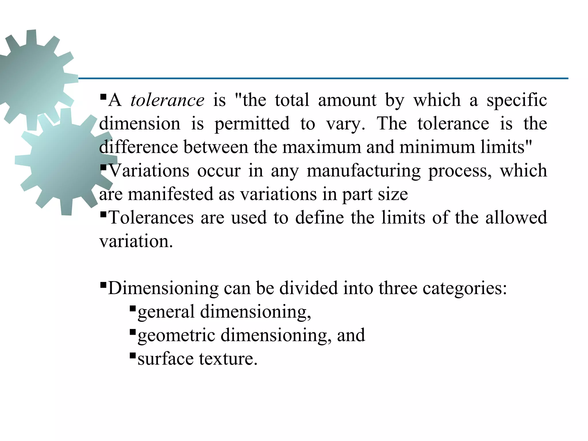
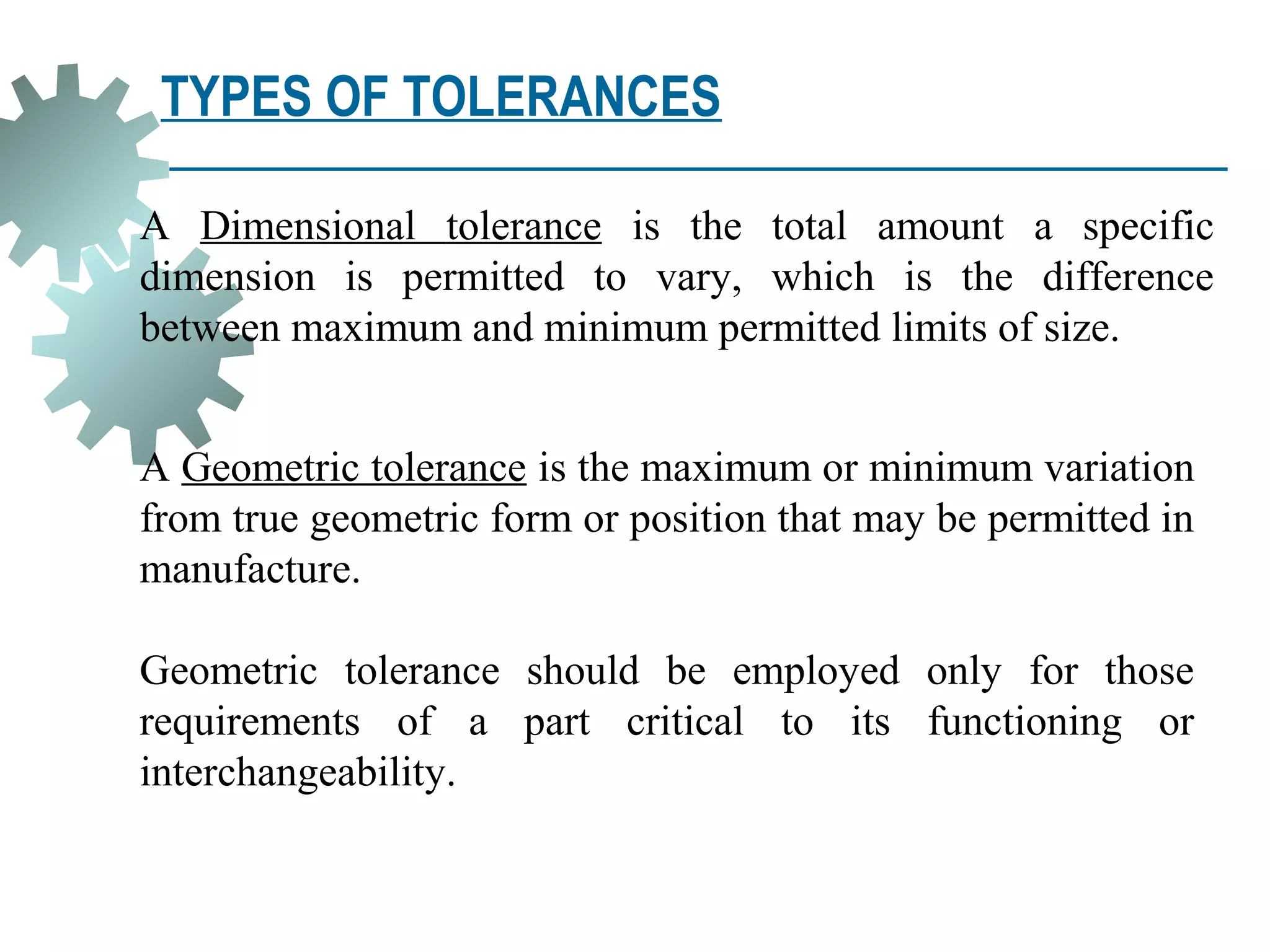
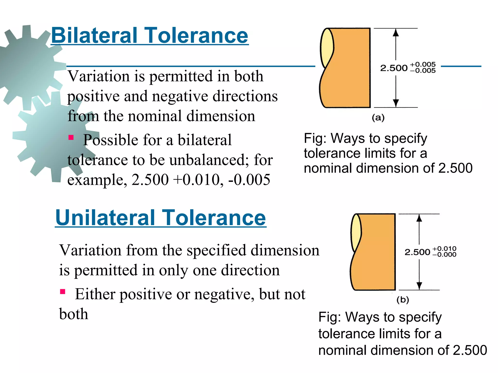


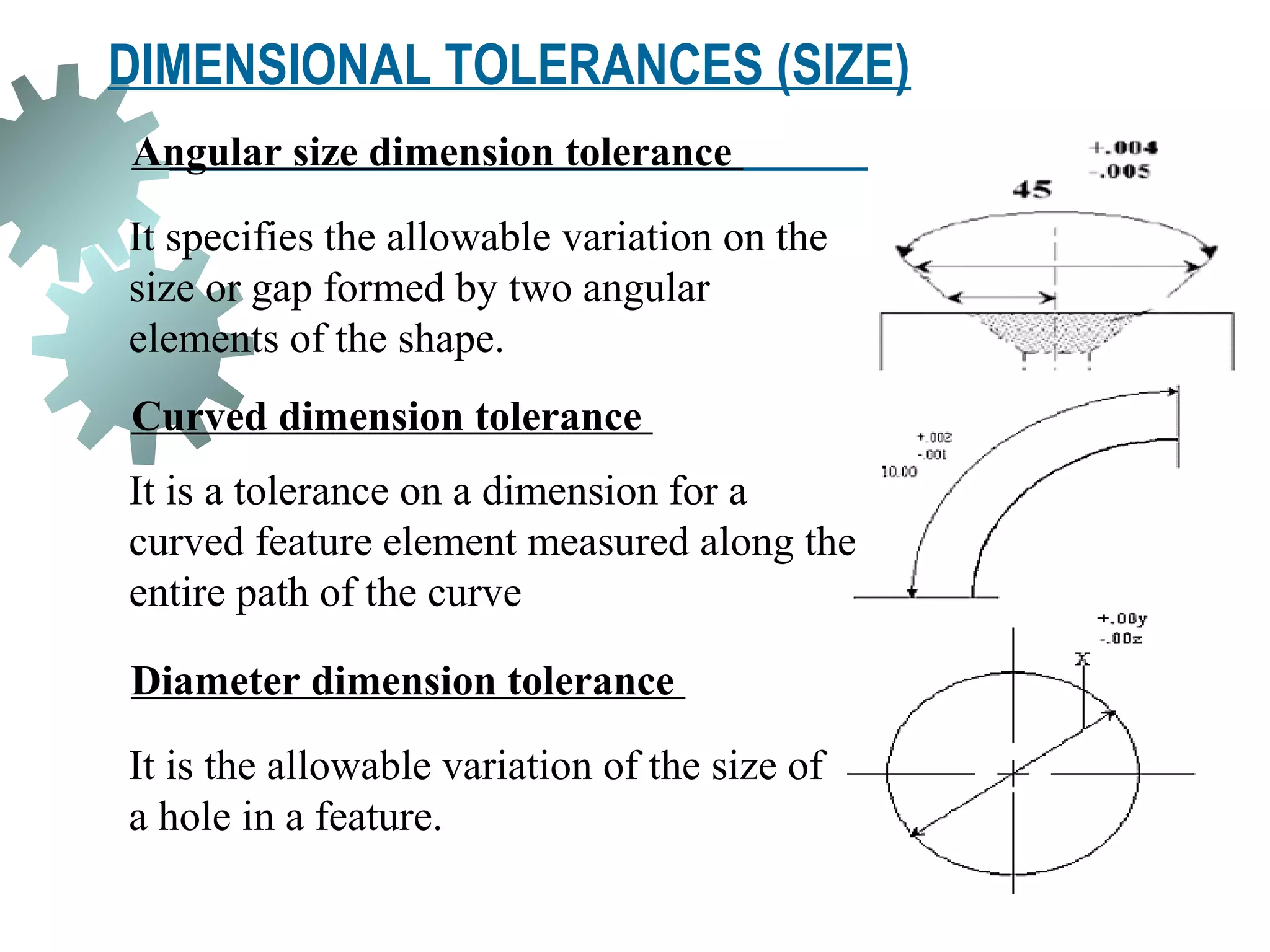
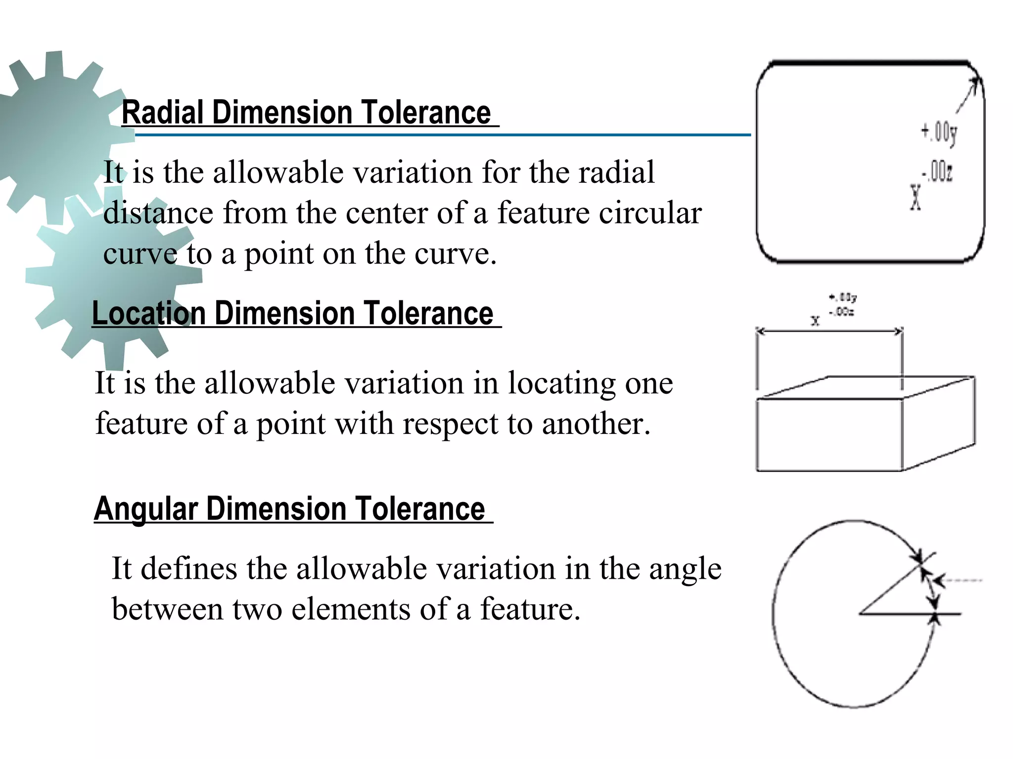


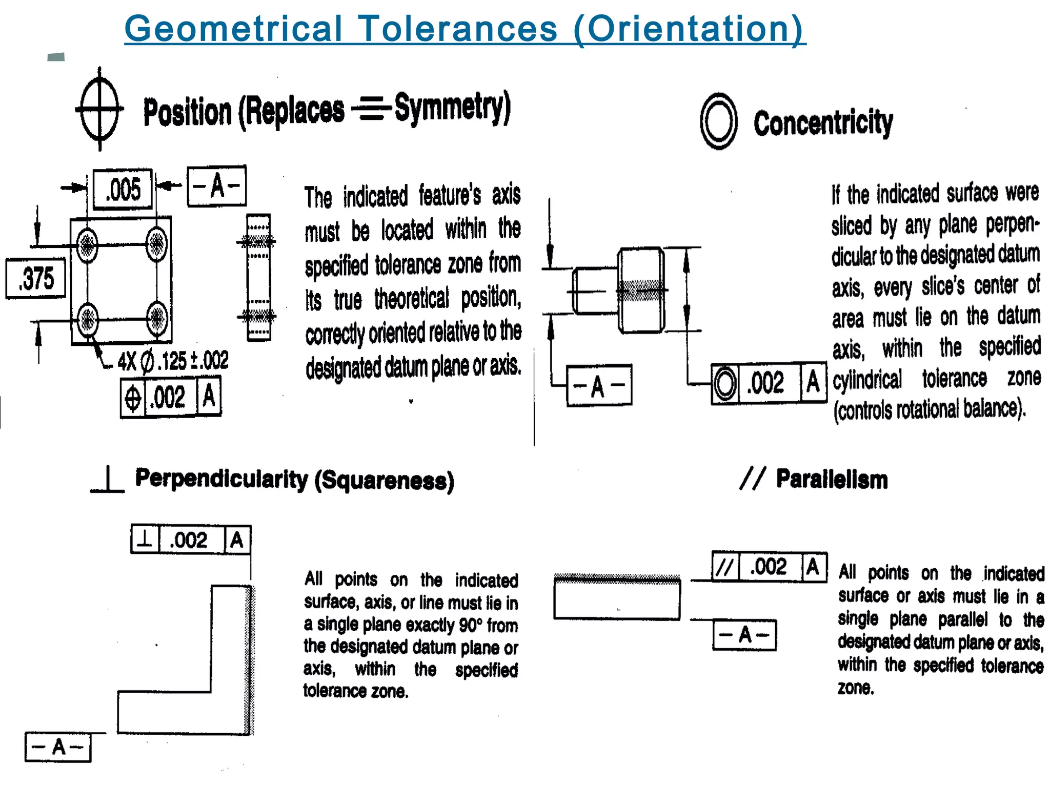


Dimensions and tolerances are critical specifications for manufactured parts. Dimensions indicate the nominal size of a part feature, while tolerances define the acceptable variation from that nominal size. There are different types of tolerances, including dimensional tolerances for linear sizes and geometric tolerances for form, orientation, and location. Specifying tolerances properly is important for assembly and interchangeability of parts while accounting for normal manufacturing variations.