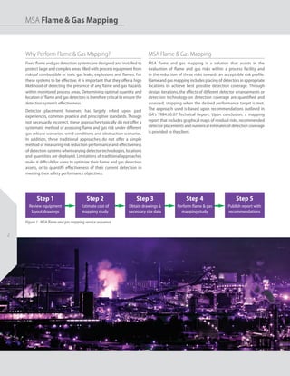
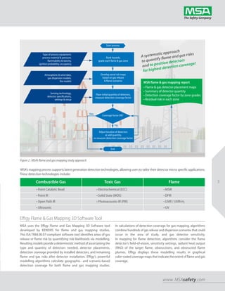
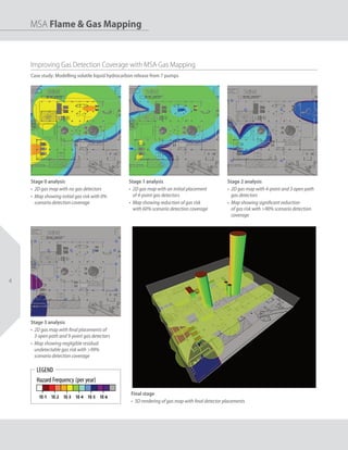
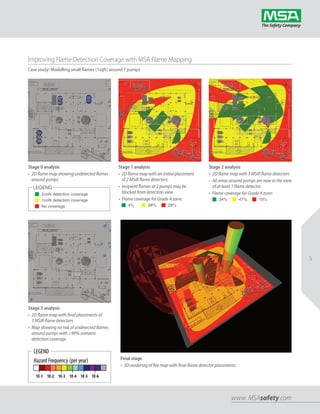
Because every life has a purpose...
MSA Fixed Gas & Flame Detection
Flame & Gas Mapping Solutions
MSA Flame & Gas Mapping
Instrument Specialties, Inc. | Sanford, FL USA | 407.324.7800 | www.isisales.com
MSA Flame & Gas Mapping
22
Why Perform Flame & Gas Mapping?
Fixed flame and gas detection systems are designed and installed to
protect large and complex areas filled with process equipment from
risks of combustible or toxic gas leaks, explosions and flames. For
these systems to be effective, it is important that they offer a high
likelihood of detecting the presence of any flame and gas hazards
within monitored process areas. Determining optimal quantity and
location of flame and gas detectors is therefore critical to ensure the
detection system’s effectiveness.
Detector placement however, has largely relied upon past
experiences, common practice and prescriptive standards. Though
not necessarily incorrect, these approaches typically do not offer a
systematic method of assessing flame and gas risk under different
gas release scenarios, wind conditions and obstruction scenarios.
In addition, these traditional approaches do not offer a simple
method of measuring risk reduction performance and effectiveness
of detection systems when varying detector technologies, locations
and quantities are deployed. Limitations of traditional approaches
make it difficult for users to optimize their flame and gas detection
assets, or to quantify effectiveness of their current detection in
meeting their safety performance objectives.
MSA Flame & Gas Mapping
MSA flame and gas mapping is a solution that assists in the
evaluation of flame and gas risks within a process facility and
in the reduction of these risks towards an acceptable risk profile.
Flame and gas mapping includes placing of detectors in appropriate
locations to achieve best possible detection coverage. Through
design iterations, the effects of different detector arrangements or
detection technology on detection coverage are quantified and
assessed, stopping when the desired performance target is met.
The approach used is based upon recommendations outlined in
ISA's TR84.00.07 Technical Report. Upon conclusion, a mapping
report that includes graphical maps of residual risks, recommended
detector placements and numerical estimates of detection coverage
is provided to the client.
Step 1
Review equipment
layout drawings
Step 2
Estimate cost of
mapping study
Step 3
Obtain drawings &
necessary site data
Step 4
Perform flame & gas
mapping study
Step 5
Publish report with
recommendations
Figure 1 : MSA flame and gas mapping service sequence
3
www. MSAsafety.com
Figure 2 : MSA’s flame and gas mapping study approach
Type of process equipment,
process material & pressure,
flammability & toxicity,
ignition probability, occupancy
Atmospheric & wind data,
gas dispersion models,
fire models
Sensing technology,
detector specifications,
settings & setup
Rank hazards,
grade each flame & gas zone
Develop zonal risk maps
based on gas release
& flame scenarios
Place initial quantity of detectors,
measure detection coverage factor
MSA flame & gas mapping report
• Flame & gas detector placement maps
• Summary of detector quantity
• Detection coverage factor by zone grades
• Residual risk in each zone
Effigy Flame & Gas Mapping 3D Software Tool
Start process
Coverage factor OK?
A systematic approach
to quantify flame and gas risks
and to position detectors
for highest detection coverage!
MSA’s mapping process supports latest generation detection technologies, allowing users to tailor their detector mix to specific applications.
These detection technologies include:
Combustible Gas Toxic Gas Flame
• Point Catalytic Bead • Electrochemical (ECC) • MSIR
• Point IR • Solid State (MOS) • DFIR
• Open Path IR • Photoacoustic-IR (PIR) • UVIR / UVIR-H2
• Ultrasonic • UV
MSA uses the Effigy Flame and Gas Mapping 3D Software tool
developed by KENEXIS for flame and gas mapping studies.
This ISA TR84.00.07-compliant software tool identifies areas of gas
release or flame risk by quantifying risk likelihoods via modelling.
Resulting models provide a deterministic method of ascertaining the
type and quantity of detectors needed, detector placements,
detection coverage provided by installed detectors, and remaining
flame and gas risks after detector installation. Effigy’s powerful
modelling algorithms calculate geographic- and scenario-based
detection coverage for both flame and gas mapping studies.
In calculations of detection coverage for gas mapping, algorithms
combine hundreds of gas release and dispersion scenarios that could
occur in the area of study, and gas detector sensitivity.
In mapping for flame detection, algorithms consider the flame
detector’s field-of-vision, sensitivity settings, radiant heat output
(RHO) of the target flame, obstructions, and obstructed flame
plumes. Effigy displays these modelling results in graphical
color-coded coverage maps that indicate the extent of flame and gas
coverage.
Adjust location of detectors
or add quantity,
re-measure detection coverage factor
End
Yes
No
44
MSA Flame & Gas Mapping
Improving Gas Detection Coverage with MSA Gas Mapping
Case study: Modelling volatile liquid hydrocarbon release from 7 pumps
Stage 0 analysis
• 2D gas map with no gas detectors
• Map showing initial gas risk with 0%
scenario detection coverage
Stage 1 analysis
• 2D gas map with an initial placement
of 4-point gas detectors
• Map showing reduction of gas risk
with 60% scenario detection coverage
Stage 2 analysis
• 2D gas map with 4-point and 3 open path
gas detectors
• Map showing significant reduction
of gas risk with >90% scenario detection
coverage
Stage 3 analysis
• 2D gas map with final placements of
3 open path and 9-point gas detectors
• Map showing negligible residual
undetectable gas risk with >99%
scenario detection coverage
Final stage
• 3D rendering of gas map with final detector placements
5
www. MSAsafety.com
Improving Flame Detection Coverage with MSA Flame Mapping
Case study: Modelling small flames (1sqft) around 7 pumps
Stage 0 analysis
• 2D flame map showing undetected flames
around pumps
Stage 3 analysis
• 2D flame map with final placements of
3 MSIR flame detectors
• Map showing no risk of undetected flames
around pumps with >99% scenario
detection coverage
Final stage
• 3D rendering of fire map with final flame detector placements
Stage 1 analysis
• 2D flame map with an initial placement
of 2 MSIR flame detectors
• Incipient flames at 2 pumps may be
blocked from detection view
• Flame coverage for Grade A zone:
Stage 2 analysis
• 2D flame map with 3 MSIR flame detectors
• All areas around pumps are now in the view
of at least 1 flame detector
• Flame coverage for Grade A zone:
LEGEND
n 2ooN detection coverage
n 1ooN detection coverage
n No coverage n 4% n 68% n 28%
n 34% n 47% n 19%
MSAsafety.com
Note:This Bulletin contains only a general
description of the products shown.While uses
and performance capabilities are described,
under no circumstances shall the products be
used by untrained or unqualified individuals
and not until the product instructions
including any warnings or cautions provided
have been thoroughly read and understood.
Only they contain the complete
and detailed information
concerning proper use and
care of these products.
ID 0700-74-MC / January 2016
© MSA 2016 Printed in U.S.A.
MSA – The Safety Company
1000 Cranberry Woods Drive
Cranberry Township, PA 16066 USA
Phone 724-776-8600
www.MSAsafety.com
Design detector layouts for highest detection coverage
Ask for MSA flame & gas mapping
MSA North America
NAmerica.mapping@MSAsafety.com
Lake Forest, CA USA
Phone: (1) 949 699 4464
Houston, TX USA
Phone: (1) 281 855 6000
MSA Latin America
SAmerica.mapping@MSAsafety.com
Querétaro, Mexico
Phone: (52) 442 2273 90 - x3973
Bogota, Colombia
Phone: (57) 1 896 6750 - x103
BRAZIL.mapping@MSAsafety.com
Sao Paulo, Brazil
Phone: (55) 11 4070 5999
MSA Europe
EUROPE.mapping@MSAsafety.com
Berlin, Germany
Phone: (49) 30 68 86 - x555
MSA China
CHINA.mapping@MSAsafety.com
Shanghai, PRC
Phone: (86) 0512 6289 8880 - x3606
MSA Middle East
MIDEAST.mapping@MSAsafety.com
Dubai, UAE
Phone: (971) 4 299 6741
MSA Pacific Asia
PACIFICA.mapping@MSAsafety.com
Singapore
Phone: (65) 6482 1921
Rayong, Thailand
Phone: (66) 3869 1427-8

Gas and Flame Detector Mapping

  • 1.
    Because every lifehas a purpose... MSA Fixed Gas & Flame Detection Flame & Gas Mapping Solutions MSA Flame & Gas Mapping Instrument Specialties, Inc. | Sanford, FL USA | 407.324.7800 | www.isisales.com
  • 2.
    MSA Flame &Gas Mapping 22 Why Perform Flame & Gas Mapping? Fixed flame and gas detection systems are designed and installed to protect large and complex areas filled with process equipment from risks of combustible or toxic gas leaks, explosions and flames. For these systems to be effective, it is important that they offer a high likelihood of detecting the presence of any flame and gas hazards within monitored process areas. Determining optimal quantity and location of flame and gas detectors is therefore critical to ensure the detection system’s effectiveness. Detector placement however, has largely relied upon past experiences, common practice and prescriptive standards. Though not necessarily incorrect, these approaches typically do not offer a systematic method of assessing flame and gas risk under different gas release scenarios, wind conditions and obstruction scenarios. In addition, these traditional approaches do not offer a simple method of measuring risk reduction performance and effectiveness of detection systems when varying detector technologies, locations and quantities are deployed. Limitations of traditional approaches make it difficult for users to optimize their flame and gas detection assets, or to quantify effectiveness of their current detection in meeting their safety performance objectives. MSA Flame & Gas Mapping MSA flame and gas mapping is a solution that assists in the evaluation of flame and gas risks within a process facility and in the reduction of these risks towards an acceptable risk profile. Flame and gas mapping includes placing of detectors in appropriate locations to achieve best possible detection coverage. Through design iterations, the effects of different detector arrangements or detection technology on detection coverage are quantified and assessed, stopping when the desired performance target is met. The approach used is based upon recommendations outlined in ISA's TR84.00.07 Technical Report. Upon conclusion, a mapping report that includes graphical maps of residual risks, recommended detector placements and numerical estimates of detection coverage is provided to the client. Step 1 Review equipment layout drawings Step 2 Estimate cost of mapping study Step 3 Obtain drawings & necessary site data Step 4 Perform flame & gas mapping study Step 5 Publish report with recommendations Figure 1 : MSA flame and gas mapping service sequence
  • 3.
    3 www. MSAsafety.com Figure 2: MSA’s flame and gas mapping study approach Type of process equipment, process material & pressure, flammability & toxicity, ignition probability, occupancy Atmospheric & wind data, gas dispersion models, fire models Sensing technology, detector specifications, settings & setup Rank hazards, grade each flame & gas zone Develop zonal risk maps based on gas release & flame scenarios Place initial quantity of detectors, measure detection coverage factor MSA flame & gas mapping report • Flame & gas detector placement maps • Summary of detector quantity • Detection coverage factor by zone grades • Residual risk in each zone Effigy Flame & Gas Mapping 3D Software Tool Start process Coverage factor OK? A systematic approach to quantify flame and gas risks and to position detectors for highest detection coverage! MSA’s mapping process supports latest generation detection technologies, allowing users to tailor their detector mix to specific applications. These detection technologies include: Combustible Gas Toxic Gas Flame • Point Catalytic Bead • Electrochemical (ECC) • MSIR • Point IR • Solid State (MOS) • DFIR • Open Path IR • Photoacoustic-IR (PIR) • UVIR / UVIR-H2 • Ultrasonic • UV MSA uses the Effigy Flame and Gas Mapping 3D Software tool developed by KENEXIS for flame and gas mapping studies. This ISA TR84.00.07-compliant software tool identifies areas of gas release or flame risk by quantifying risk likelihoods via modelling. Resulting models provide a deterministic method of ascertaining the type and quantity of detectors needed, detector placements, detection coverage provided by installed detectors, and remaining flame and gas risks after detector installation. Effigy’s powerful modelling algorithms calculate geographic- and scenario-based detection coverage for both flame and gas mapping studies. In calculations of detection coverage for gas mapping, algorithms combine hundreds of gas release and dispersion scenarios that could occur in the area of study, and gas detector sensitivity. In mapping for flame detection, algorithms consider the flame detector’s field-of-vision, sensitivity settings, radiant heat output (RHO) of the target flame, obstructions, and obstructed flame plumes. Effigy displays these modelling results in graphical color-coded coverage maps that indicate the extent of flame and gas coverage. Adjust location of detectors or add quantity, re-measure detection coverage factor End Yes No
  • 4.
    44 MSA Flame &Gas Mapping Improving Gas Detection Coverage with MSA Gas Mapping Case study: Modelling volatile liquid hydrocarbon release from 7 pumps Stage 0 analysis • 2D gas map with no gas detectors • Map showing initial gas risk with 0% scenario detection coverage Stage 1 analysis • 2D gas map with an initial placement of 4-point gas detectors • Map showing reduction of gas risk with 60% scenario detection coverage Stage 2 analysis • 2D gas map with 4-point and 3 open path gas detectors • Map showing significant reduction of gas risk with >90% scenario detection coverage Stage 3 analysis • 2D gas map with final placements of 3 open path and 9-point gas detectors • Map showing negligible residual undetectable gas risk with >99% scenario detection coverage Final stage • 3D rendering of gas map with final detector placements
  • 5.
    5 www. MSAsafety.com Improving FlameDetection Coverage with MSA Flame Mapping Case study: Modelling small flames (1sqft) around 7 pumps Stage 0 analysis • 2D flame map showing undetected flames around pumps Stage 3 analysis • 2D flame map with final placements of 3 MSIR flame detectors • Map showing no risk of undetected flames around pumps with >99% scenario detection coverage Final stage • 3D rendering of fire map with final flame detector placements Stage 1 analysis • 2D flame map with an initial placement of 2 MSIR flame detectors • Incipient flames at 2 pumps may be blocked from detection view • Flame coverage for Grade A zone: Stage 2 analysis • 2D flame map with 3 MSIR flame detectors • All areas around pumps are now in the view of at least 1 flame detector • Flame coverage for Grade A zone: LEGEND n 2ooN detection coverage n 1ooN detection coverage n No coverage n 4% n 68% n 28% n 34% n 47% n 19%
  • 6.
    MSAsafety.com Note:This Bulletin containsonly a general description of the products shown.While uses and performance capabilities are described, under no circumstances shall the products be used by untrained or unqualified individuals and not until the product instructions including any warnings or cautions provided have been thoroughly read and understood. Only they contain the complete and detailed information concerning proper use and care of these products. ID 0700-74-MC / January 2016 © MSA 2016 Printed in U.S.A. MSA – The Safety Company 1000 Cranberry Woods Drive Cranberry Township, PA 16066 USA Phone 724-776-8600 www.MSAsafety.com Design detector layouts for highest detection coverage Ask for MSA flame & gas mapping MSA North America NAmerica.mapping@MSAsafety.com Lake Forest, CA USA Phone: (1) 949 699 4464 Houston, TX USA Phone: (1) 281 855 6000 MSA Latin America SAmerica.mapping@MSAsafety.com Querétaro, Mexico Phone: (52) 442 2273 90 - x3973 Bogota, Colombia Phone: (57) 1 896 6750 - x103 BRAZIL.mapping@MSAsafety.com Sao Paulo, Brazil Phone: (55) 11 4070 5999 MSA Europe EUROPE.mapping@MSAsafety.com Berlin, Germany Phone: (49) 30 68 86 - x555 MSA China CHINA.mapping@MSAsafety.com Shanghai, PRC Phone: (86) 0512 6289 8880 - x3606 MSA Middle East MIDEAST.mapping@MSAsafety.com Dubai, UAE Phone: (971) 4 299 6741 MSA Pacific Asia PACIFICA.mapping@MSAsafety.com Singapore Phone: (65) 6482 1921 Rayong, Thailand Phone: (66) 3869 1427-8