128 Bit Parallel Prefix Tree Structure Comparator
•
1 like•591 views

A 128 bit comparator is designed with conventional digital cmos gates that make use of parallel prefix tree structure. The comparison is performed bit wise proceeding from most significant bit to least significant bit. The comparison of lower bits is carried only when the most significant bits are equal which decreases the power dissipation in the circuit. To make the circuit regular the design is made using only cmos logic gates. The transmission gates used in the existing design are replaced with the simple AND gates so that the entire circuit can be designed in gate level. This 128 bit comparator is designed in cadence environment using tsmc 0.18μm technology with a power dissipation of 0.28mw and with a delay of 0.09ms.

Recommended
Recommended
More Related Content
What's hot
What's hot (20)
Viewers also liked
Similar to 128 Bit Parallel Prefix Tree Structure Comparator
Similar to 128 Bit Parallel Prefix Tree Structure Comparator (20)
More from IJRES Journal
More from IJRES Journal (20)
Recently uploaded
Recently uploaded (20)
128 Bit Parallel Prefix Tree Structure Comparator
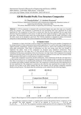
- 1. International Journal of Research in Engineering and Science (IJRES) ISSN (Online): 2320-9364, ISSN (Print): 2320-9356 www.ijres.org Volume 3 Issue 10 ǁ October. 2015 ǁ PP.43-51 www.ijres.org 43 | Page 128 Bit Parallel Prefix Tree Structure Comparator S. ChandraSekhar1 , J. Lakshmi Prasanna2 1 Assistant Professor, Department of Electronics and Communication Engineering, Dhanekula institute of engineering and technology, Vijayawada, India. 2 PG scholar, Dhanekula institute of engineering and technology, Vijayawada, India. Abstract- A 128 bit comparator is designed with conventional digital cmos gates that make use of parallel prefix tree structure. The comparison is performed bit wise proceeding from most significant bit to least significant bit. The comparison of lower bits is carried only when the most significant bits are equal which decreases the power dissipation in the circuit. To make the circuit regular the design is made using only cmos logic gates. The transmission gates used in the existing design are replaced with the simple AND gates so that the entire circuit can be designed in gate level. This 128 bit comparator is designed in cadence environment using tsmc 0.18µm technology with a power dissipation of 0.28mw and with a delay of 0.09ms. I. INTRODUCTION Comparator is a logic circuit that is used to compare the magnitude of two given numbers. Comparators are key design elements in many mathematical and scientific applications. It is used in wide range of applications to support scientific computations, signature analysis and test circuits etc. Some of the comparators are designed using adder architectures. These types of architectures are slow and occupy more area even though we implement fast adders. Some of the comparators are designed using multiplexer architectures. These architectures divide the n bit input into 2 n/2 bits and the result of two n/2 comparators is given to the multiplexer but the power consumption of the circuit becomes very high. Some of the comparators are designed using all N transistor (ANT) circuits. But all the nmos transistors connected in series enter into saturation mode during operation which leads to overall increase in conductive resistance. Some of the comparators use priority encoder architectures. These architectures divide the n bit input into 2 n/2 bits and the result of two n/2 comparators is given to the priority encoder so that it considers the msb priority first. Here in our project we use parallel prefix architecture. In this architecture the n bit inputs are divided into n/4 modules each module compares individual 4 bits. The comparison is carried from the most significant bit to the least significant bit. The comparison is carried out only when the most significant bits are equal. If at all a decision can be taken in the initial modules then the next modules will not perform comparison operation thereby saving the power. The details about this architecture can be studied from the following chapter. Figure1: Block diagram of 128 bit comparator architecture with comparison module and decision module The comparator comparison module is a parallel prefix structure that performs bitwise comparison of 128 bit operands. The input operands A and B are denoted as A128,A127,A126………A2,A1,A0 and B128,B127,B126…….. B2, B1, B0. The comparator resolution module performs bit wise comparison from MSB to
- 2. 128 Bit Parallel Prefix Tree Structure Comparator www.ijres.org 44 | Page LSB such that the comparison is triggered only when the higher order of bits are equal. The comparison resolution module encodes the comparison bits into two buses that is left bus and right bus such that each bus stores the partial comparison result as each bit is compared such that If An > Bn then left n = 1 and right n = 0 An> Bn then left n = 0 and right n = 1 An = Bn then left n = 0 and right n = 0 The decision module uses or-network to make a final comparison decision based on the bits of left bus and rights bus. If lr =00 then A = B lr = 01 then A < B lr = 10 then A > B II. COMPARATOR ARCHITECTURE Figure2: 128 Bit Comparator Architecture The comparator architecture consists of comparison module and the decision module. The comparison module performs the comparison of the give input bits. As we are designing a 128 bit comparator the 128 bits are grouped into 4 bits and each four bits are compared in a single module and we have 32 modules each comparing 4 bits. Each 4 bit comparator module takes two 4 bit input operands one enable signal from the previous comparator module. This enable signal helps in triggering the present module for comparison. Each 4 bit comparator module has 4 outputs that are associated with the decision module and one enable output that acts as enable input for the next comparator module for comparison. The decision module gets its input from the comparison module. Each comparison module gives 4 outputs for 4 input bits. In this way we get a total of 128 outputs from the comparison module each single output for 128 inputs. Each four inputs are combined to get a single output. This procedure is followed until we get our final 3 outputs which are A greater than B (A>B), A less than B (A<B), A equal to B (A=B). Each 4 bit comparator module of the comparison module is again divided into five hierarchical set elements that perform the comparison operation in a serial manner. We partition the comparator resolution module structure into five hierarchal prefixing sets.
- 3. 128 Bit Parallel Prefix Tree Structure Comparator www.ijres.org 45 | Page Figure3: Tree structure of comparison module III. COMPARATOR DESIGN The comparison module performs bitwise comparison using a tree structure. In the comparison module we use five Sets of elements. Each set performs an individual operation of comparison. Set -1 performs comparison of two individual bits of A and B. The output of set-1 acts as the input of set-2 .set-2 combines the output of four set-1 outputs. The output of set-2 acts as input to set-3. The output of set-3 acts as enable input to set-4 elements. The output of set-4 element acts as enable input to set-5 element. The output of set-5 element forms right and left bus bits. The right and left bus bits from the comparison module are given to the decision module which performs or-operation and decides whether A is greater than B or A is less than B or A is equal to B. Set 1 compares the N-bit operands A and B bit-by-bit, using a single level of set 1type cells. The set_1type cells provide a termination flag Di to cells in sets 2 and 4, indicating whether the computation should terminate or to proceed. These cells compute XOR operation. Set 2 consists of set _2 type cells, which combine the termination flags for each of the four cells from set 1 (each _2-type cell combines the termination flags of one 4-b partition) using NOR-logic to limit the fan-in and fan-out to a maximum of four. The set _2type cells either continue the comparison for bits of lesser significance if all four inputs are 0s, or terminate the comparison if a final decision can be made. For 0 ≤ m ≤ N/4–1, there is a total of N/4 _2-type cells, all functioning in parallel Set 3 consists of set_3-type cells, which are similar to set _2 type cells, but can have more logic levels, different inputs, and carry different triggering points. Set_3 type cells provide no comparison functionality. The cell’s sole purpose is to limit the fan-in and fan-out regardless of operand bit width. To limit the set _3-type cell’s, the number of levels in set 3 increases if the fan-in exceeds four. Set 3 provides functionality similar to set 2 using the AND logic to continue or terminate the bitwise comparison activity. If the comparison is terminated, set 3 signals set 4 to set the left bus and right bus bits to 0 for all bits of lower significance. For 0 ≤ m ≤ N/4 − 1, there is a total of N/4 set _3 type cells per level. From left to right, the first four set_3 type cells in set 3 combine the 4-b partition comparison outcomes from the one, two, three, and four 4-b partitions of set 2. Since the fourth set_3 type cell has a fan-in of four, the number of levels in set 3 increases and set 3’s fifth cell combines the comparison outcomes of the first 16 MSBs with a fan-in of only two and a fan-out of one. S3,m =S2,m-1.S2,m Where m indicates the module number S2,m indicates the output from present module set-2 S2,m-1 indicates the set-2 output from previous module Set 4 consists of cells, whose outputs control the select inputs of set_5 type cells in set 5, which in turn drive both the left bus and the right bus. For an set 5-type cell and the 4-b partition to which the cell belongs, bitwise
- 4. 128 Bit Parallel Prefix Tree Structure Comparator www.ijres.org 46 | Page comparison outcomes from set 1 provide information about the more significant bits. The number of inputs in the set 4 type cells increases from left to right in each partition, ending with a fan-in of five. Thus, set 4 determine whether set 5 propagates the bitwise comparison codes or not. Set 5 performs the functionality of a multiplexer that is it shows whether the bit from the input A is greater or vice versa set_5 gives 2 bit output. The select control input is based on the set_4 type cell output from set 4. We define the 2-b as the left-bit code li and the right-bit code ri where all left-bit codes and all right-bit codes combine to form the left bus and the right bus, respectively. The output F denotes the ―greater-than,‖ ―less- than,‖ or ―equal to‖ final comparison decision S5iai = s4i(ai) S5ibi = s4i(bi) F =S5iai S5ibi 00, for Ai = Bi 01, for Ai < Bi 10, for Ai > Bi . Essentially, the 2-b code F can be realized by OR-ing all left bits and all right bits separately, in the decision module using an OR-gate network. Figure4: Design of a single module (4-bit) comparator IV. IMPLEMENTING 128 BIT COMPARATOR IN A SORTER Sorting is a fundamental operation in which the given sequence of elements is arranged in a specific order. We see many applications of sorting in our daily life. If we consider a database of students in a college they are arranged in a sequence either in alphabetical order or roll number wise or date of admission etc., not only in colleges we can also see the applications of sorting in various scientific fields. The basic element in the sorting circuit is comparison element. We use a magnitude comparator as a key element in the sorting circuit. The
- 5. 128 Bit Parallel Prefix Tree Structure Comparator www.ijres.org 47 | Page comparator compares two elements and produces three outputs greater than, less than and equal to. Based on these outputs the sorting circuit uses a swapping module so that the elements in the given sequence are sorted in a desired order. Figure5: Basic sorting I.O architecture Figure6: Basic sorting D.O architecture Bitonic sequence is a sequence that has one monotonic increasing sequence and one monotonic decreasing sequence. Because of the two monotonic sequences it is called bitonic sequence. Bitonic sorting divides the given n numbered sequence into two n/2 sequences out of which one is sorted in ascending order and the second n/2 sequence is sorted in descending order. Whether the increasing order sorting has to be performed first or decreasing order sorting has to be performed first depends on our sorting order. If at all we have to perform sorting in an increasing order then the first n/2 sequence is sorted in increasing order and the second n/2 sequence is sorted in the decreasing order. All the elements in the first n/2 sequence will be less than or equal to the elements in the second n/2 sequence. If at all we have to perform sorting in a decreasing order then the first n/2 sequence is sorted in decreasing order and the second n/2 sequence is sorted in the increasing order. All the elements in the first n/2 sequence will be greater than or equal to the elements in the second n/2 sequence. Then the two n/2 sequences are sorted using merge sort. The bitonic sorting network consists of two key elements. One is comparator element and the other is swapping element. The comparator compares two elements and produces three outputs greater than, less than and equal to. Based on these outputs the sorting circuit uses a swapping module so that the elements in the given sequence are sorted in a desired order. Figure7: General bitonic sorting module for increasing order sorting Figure8: General bitonic sorting module for decreasing order sorting
- 6. 128 Bit Parallel Prefix Tree Structure Comparator www.ijres.org 48 | Page The general bitonic sorting to sort the elements in increasing order is performed as below Figure9: Example for ascending order bitonic sorting The general comparator module used in the sorting is replaced by the 1128 bit parallel prefix tree structure comparator and is as shown in the figure 10 Figure10: Implementation of comparator in 16 numbered sequence bitonic sorter V. RESULTS Figure11: output of the comparator showing all the results a>b, a=b & a<b
- 7. 128 Bit Parallel Prefix Tree Structure Comparator www.ijres.org 49 | Page Figure12: RTL for 4 stages of comparator (16 bit) Figure13: Layout for 128 bit comparator Figure14: simulation results for bitonic sorter performing 4 types of sorting orders VI. POWER ANALYSIS No of bits Leakage power(µw) Dynamic power(mw) 16 0.05 0.03 32 0.1 0.07 48 0.16 0.11 64 0.22 0.14 80 0.27 0.17 96 0.33 0.21 112 0.38 0.25 128 0.44 0.28 Table: 1 power dissipation for various bit comparators
- 8. 128 Bit Parallel Prefix Tree Structure Comparator www.ijres.org 50 | Page As the number of bits increases the power dissipated by the comparator architecture increases. The Power dissipated for various bits of comparators are shown below. 0 0.05 0.1 0.15 0.2 0.25 0.3 0.35 0.4 0.45 16 bit 48 bit 80 bit 112 bit Leakage power(µw) Dynamic power(mw) Figure15: power dissipation for various bits of comparator VII. CONCLUSION We have designed 128 bit comparator using parallel prefix tree architecture. This architecture consists of parallel structure which helps in replicating the design which supports VLSI reconfigurable topology. All the cells used in this architecture are logic gates which makes use of cmos logic. The comparator dissipates a power of 0.2mw and has a delay of 0.5ms. By using this 128 bit comparator we designed a sorter that sorts 16 numbers in four different sorting orders using bitonic sorting method. REFERENCES [1.] Saleh Abdel-Hafeez and Ann Gordon-Ross, Scalable Digital CMOS Comparator Using a Parallel Prefix Tree IEEE TRANSACTIONS ON VERY LARGE SCALE INTEGRATION (VLSI) SYSTEMS, VOL. 21, NO. 11, NOVEMBER 2013 [2.] H. J. R. Liu and H. Yao, High-Performance VLSI Signal Processing Innovative Architectures and Algorithms, vol. 2. Piscataway, NJ: IEEE Press, 1998. [3.] Y. Sheng and W. Wang, ―Design and implementation of compression algorithm comparator for digital image processing on component,‖ in Proc. 9th Int. Conf. Young Comput. Sci., Nov. 2008, pp. 1337–1341. [4.] B. Parhami, ―Efficient hamming weight comparators for binary vectors based on accumulative and up/down parallel counters,‖ IEEE Trans. Circuits Syst., vol. 56, no. 2, pp. 167–171, Feb. 2009. [5.] A. H. Chan and G. W. Roberts, ―A jitter characterization system using a component-invariant Vernier delay line,‖ IEEE Trans. Very Large Scale Integr. (VLSI) Syst., vol. 12, no. 1, pp. 79–95, Jan. 2004. [6.] M. Abramovici, M. A. Breuer, and A. D. Friedman, Digital Systems Testing and Testable Design, Piscataway, NJ: IEEE Press, 1990. [7.] H. Suzuki, C. H. Kim, and K. Roy, ―Fast tag comparator using diode partitioned domino for 64-bit microprocessor,‖ IEEE Trans. Circuits Syst. I, vol. 54, no. 2, pp. 322–328, Feb. 2007. [8.] D. V. Ponomarev, G. Kucuk, O. Ergin, and K. Ghose, ―Energy efficient comparators for superscalar datapaths,‖ IEEE Trans. Comput., vol. 53, no. 7, pp. 892–904, Jul. 2004. [9.] V. G. Oklobdzija, ―An algorithmic and novel design of a leading zero detector circuit: Comparison with logic synthesis,‖ IEEE Trans. Very Large Scale Integr. (VLSI) Syst., vol. 2, no. 1, pp. 124–128, Mar. 1994. [10.] H. L. Helms, High Speed (HC/HCT) CMOS Guide. Englewood Cliffs, NJ: Prentice-Hall, 1989. [11.] SN7485 4-bit Magnitude Comparators, Texas Instruments, Dallas, TX, 1999. [12.] K. W. Glass, ―Digital comparator circuit,‖ U.S. Patent 5 260 680, Feb.13, 1992. [13.] D. norris, ―Comparator circuit,‖ U.S. Patent 5 534 844, Apr. 3, 1995. [14.] W. Guangjie, S. Shimin, and J. Lijiu, ―New efficient design of digital comparator,‖ in Proc. 2nd Int. Conf. Appl. Specific Integr. Circuits, 1996, pp. 263–266. [15.] S. Abdel-Hafeez, ―Single rail domino logic for four-phase clocking scheme,‖ U.S. Patent 6 265 899, Oct. 20, 2001. [16.] M. D. Ercegovac and T. Lang, Digital Arithmetic, San Mateo, CA: Morgan Kaufmann, 2004. [17.] J. P. Uyemura, CMOS Logic Circuit Design, Norwood, MA: Kluwer, 1999. [18.] 18.J. E. Stine and M. J. Schulte, ―A combined two’s complement and floating-point comparator,‖ in Proc. Int. Symp. Circuits Syst., vol. 1. 2005, pp. 89–92. [19.] S.-W. Cheng, ―A high-speed magnitude comparator with small transistor count,‖ in Proc. IEEE Int. Conf. Electron., Circuits, Syst., vol. 3. Dec. 2003, pp. 1168–1171. [20.] A. Bellaour and M. I. Elmasry, Low-Power Digital VLSI Design Circuits and Systems. Norwood, MA: Kluwer, 1995. [21.] W. Belluomini, D. Jamsek, A. K. Nartin, C. McDowell, R. K. Montoye, H. C. Ngo, and J. Sawada, ―Limited switch dynamic logic circuits for high-speed low-power circuit design,‖ IBM J. Res. Develop., vol. 50, nos. 2–3, pp. 277–286, Mar.–May 2006. [22.] C.-C. Wang, C.-F. Wu, and K.-C. Tsai, ―1 GHz 64-bit high-speed comparator using ANT dynamic logic with two-phase clocking,‖ in IEE Proc.-Comput. Digit. Tech., vol. 145, no. 6, pp. 433–436, Nov. 1998. [23.] C.-C. Wang, P.-M. Lee, C.-F. Wu, and H.-L. Wu, ―High fan-in dynamic CMOS comparators with low transistor count,‖ IEEE Trans. Circuits Syst. I, vol. 50, no. 9, pp. 1216–1220, Sep. 2003. [24.] N. Maheshwari and S. S. Sapatnekar, ―Optimizing large multiphase level-clocked circuits,‖ IEEE Trans. Comput.-Aided Design Integr. Circuits Syst., vol. 18, no. 9, pp. 1249–1264, Nov. 1999.
- 9. 128 Bit Parallel Prefix Tree Structure Comparator www.ijres.org 51 | Page [25.] C.-H. Huang and J.-S. Wang, ―High-performance and power-efficient CMOS comparators,‖ IEEE J. Solid-State Circuits, vol. 38, no. 2, pp. 254–262, Feb. 2003. [26.] H.-M. Lam and C.-Y. Tsui, ―A mux-based high-performance single-cycle CMOS comparator,‖ IEEE Trans. Circuits Syst. II, vol. 54, no. 7, pp. 591–595, Jul. 2007. [27.] F. Frustaci, S. Perri, M. Lanuzza, and P. Corsonello, ―Energy-efficient single-clock-cycle binary comparator,‖ Int. J. Circuit Theory Appl., vol. 40, no. 3, pp. 237–246, Mar. 2012. [28.] P. Coussy and A. Morawiec, High-Level Synthesis: From Algorithm to Digital Circuit. New York: Springer-Verlag, 2008. [29.] S. Perri and P. Corsonello, ―Fast low-cost implementation of single clock-cycle binary comparator,‖ IEEE Trans. Circuits Syst. II, vol. 55, no. 12, pp. 1239–1243, Dec. 2008. [30.] M. D. Ercegovac and T. Lang, ―Sign detection and comparison networks with a small number of transitions,‖ in Proc. 12th IEEE Symp. Comput. Arithmetic, Jul. 1995, pp. 59–66. [31.] J. D. Bruguera and T. Lang, ―Multilevel reverse most-significant carry computation,‖ IEEE Trans. Very Large Scale Integr. (VLSI) Syst., vol. 9, no. 6, pp. 959–962, Dec. 2001. [32.] D. R. Lutz and D. N. Jayasimha, ―The half-adder form and early branch condition resolution,‖ in Proc. 13th IEEE Symp. Comput. Arithmetic, Jul. 1997, pp. 266–273. [33.] J. Hensley, M. Singh, and A. Lastra, ―A fast, energy-efficient zcomparator,‖ in Proc. ACM Conf. Graph. Hardw., 2005, pp. 41– 44. [34.] V. N. Ekanayake, I. K. Clinton, and R. Manohar, ―Dynamic significance compression for a low-energy sensor network asynchronous processor,‖in Proc. 11th IEEE Int. Symp. Asynchronous Circuits Syst., Mar. 2005, pp. 144–154. [35.] H.-M. Lam and C.-Y. Tsui, ―High-performance single clock cycle CMOS comparator,‖ Electron. Lett., vol. 42, no. 2, pp. 75–77, Jan. 2006. [36.] J.-Y. Kim and H.-J. Yoo, ―Bitwise competition logic for compact digital comparator,‖ in Proc. IEEE Asian Solid-State Circuits Conf., Nov. 2007, pp. 59–62. [37.] M. S. Schmookler and K. J. Nowka, ―Leading zero anticipation and detection—a comparison of methods,‖ in Proc. 15th IEEE Symp. Comput. Arithmetic, Sep. 2001, pp. 7–12. 1998 [38.] 380 K.E. Batcher, ―Sorting Networks and Their Applications,‖ Proc.AFIPS Proc. Spring Joint Computer Conf. pp. 307-314, 196