SlideShare a Scribd company logo
1 of 20
Download to read offline
24/2/2013
CE 370 : Prof. Abdelhamid Charif 1
CE370
REINFORCED CONCRETE-I
Prof. Abdelhamid CHARIF
Flexural Behavior and
Analysis of RC Beams
Behavior stages in a RC beam
• A small transverse load placed on a simply supported RC beam is
gradually increased until beam failure.
• This loading causes positive bending moment (tension, and steel
in bottom) and shear force
• Perfect bond is assumed between steel bars and concrete
• The beam will go through three distinct stages before collapse
occurs. These are:
• The uncracked concrete stage
• The concrete cracked – elastic strength stage
• The ultimate – strength stage.
2
24/2/2013
CE 370 : Prof. Abdelhamid Charif 2
3
Simply supported beam under uniform load
4
Basic Assumptions in Flexure theory of RC Members
1. Plane sections before bending remain plane after bending.
This assumption has been experimentally verified for all normal
beams except deep beams (length to thickness ratio less than 3).
2. The strain in reinforcement equals to the strain in concrete at the
same level (perfect bond, no slip).
1 & 2 imply that strain in reinforcement and concrete is
directly proportional to the distance from N.A.
3. Tensile strength of concrete is neglected in flexural strength
calculations (after cracking).
4. Stresses in concrete and reinforcement are calculated from
strains using material stress-strain curves.
Other assumptions will be made at ultimate state
24/2/2013
CE 370 : Prof. Abdelhamid Charif 3
5
Recall Concrete Stress-Strain Curve
Compression: For a stress less or equal to 50% of fc’ ,
the curve is almost linear.
Tension: Strength very small and curve assumed linear.
6
Recall Steel Stress-Strain Curve
(Large plastic deformations after yielding)






ysy
ysss
s
f
E
f


when
when
gradesallfor
200000MPaEs 
24/2/2013
CE 370 : Prof. Abdelhamid Charif 4
Uncracked Concrete Stage
• At small loads when the tensile stresses are less than the
modulus of rupture, the entire cross section of the beam resists
bending.
• Standard bending theory can be used.
• Compression develops on top side and tension on bottom (for
positive moments.
7
• Neutral axis passes through
centroid
• Moment of inertia of gross
section is used
8
Uncracked Concrete Stage
Strains and stresses
24/2/2013
CE 370 : Prof. Abdelhamid Charif 5
Concrete-Cracked – Elastic Stage
• As load is increased, the modulus of rupture of the concrete is
exceeded, and cracks begin to develop in bottom of the beam.
• Cracking Moment: The moment at which tensile stress in the
bottom of the beam equals the modulus of rupture (i.e. when
cracks begin to form) is referred to as the cracking moment, Mcr
• As load is further increased, cracks quickly spread closer to the
neutral axis, which then begins to move upward.
• Note: The cracks occur at all places along the beam where the
actual moment is greater than the cracking moment.
9
Concrete-Cracked – Elastic Stage (contd.)
• As concrete in the cracked zone cannot resist tensile stresses –
the steel must do it. Perfect bond is still maintained.
• This stage will continue as long as the compression stress in the
top fibers is less than about one-half of the concrete compressive
strength fc’ and as long as steel stress is less than its yield stress
• In this stage the compressive stresses vary linearly with the
distance from the neutral axis (straight line).
10
ratioModular
with
:pointsameat thestrainsEqual



n
E
E
nnff
E
E
ff
E
f
E
f
c
s
cs
c
s
cs
s
s
c
c
sc 
24/2/2013
CE 370 : Prof. Abdelhamid Charif 6
• Service or Working Loads: Loads that actually occur when a
structure is in normal service use.
• Under working loads, moments develop which are considerably
larger than the cracking moments. Obviously the tensile side of
the beam will be cracked.
• Under working loads, concrete compression stress is less than
50% of its strength and linear stress-strain variation is assumed.
• Service loads and serviceability limit state correspond thus to
the cracked elastic stage
• To compute concrete and steel stresses in this range, the
transformed-area method is used.
11
Cracked – Elastic Stage and Service Loads
Beam Failure- Ultimate Strength Stage
• As load is increased further, compressive stresses are greater than
0.5fc’, cracks and neutral axis move further upward .
• Concrete compressive stresses begin to change appreciably from
linear to curved, and reinforcing bars yield.
12
24/2/2013
CE 370 : Prof. Abdelhamid Charif 7
Moment Curvature Diagram
• From the measured compressive strain in concrete and tensile
strain in steel, the relationship between the bending moment
and the curvature can be tracked up to failure.
13
dy
y
sc 







ntaanglessmallVery
NAfromdistancesomeatfiberbeamainstrain
curvatureorsectionbeamtheofchangeAngle


y
s
c
d

• Bending moments cause
curvatures (rotations).
• Curvature more objective
than deflection as
bending deformation.
14
Typical Moment Curvature Diagram
for a Reinforced Concrete Beam
There are three
different stages
in the curve :
OC – CY - YF
24/2/2013
CE 370 : Prof. Abdelhamid Charif 8
15
Moment Curvature Diagram
1. First stage is for moments less than the cracking moment Mcr .
The entire beam cross section is available to resist bending. The
relationship is quasi-linear.
2. When the moment is increased beyond Mcr, the slope of the
curve decreases as the cracked beam is not as stiff as in the
initial stage. The diagram will still follow a straight line from Mcr
to the point where steel is stressed to its yield point.
15
3. After steel yields, the beam has
very little additional moment
capacity, and only a small
additional load is required to
substantially increase rotations
and deflections. The slope of the
diagram is now almost flat.
Bending stress in an Uncracked Beam
• Steel area is small (usually 2% or less), and its effect on beam
properties is negligible as long as the beam is uncracked
• The bending stress in such a beam can be obtained based on
the gross properties of the beam’s cross section.
• The neutral axis coincides with the centroid
• The stress in the concrete at a distance y from the neutral axis
of the cross section can be determined from the following
flexure formula:
16
section.crossgrosstheofinertiaofMoment
sectiontheofmomentBending



g
cr
g
I
MM
I
My
f
24/2/2013
CE 370 : Prof. Abdelhamid Charif 9
Cracking Moment
17
section.crosstheofinertiaofmomentGross
momentBending



g
g
I
M
I
My
f
t
gr
cr
g
tcr
r
cr
t
y
If
M
I
yM
f
fff
yy



:Thus
9.5.2.3)sectionSBC/(ACI0.7ruptureofModulus
fibertensionextremetoaxiscentroidalfromdistance
Substitute
'
Example 1: Uncracked section
• Assuming concrete is uncracked, compute bending stresses in
extreme fibers of the section below for a bending moment of
34 kN.m. fc’ = 30 MPa.
• To check that the section is uncracked, first determine the
cracking moment of the section.
18
375
450
300
283
All dimensions in mm
24/2/2013
CE 370 : Prof. Abdelhamid Charif 10
19
Solution of Example 1
uncrackedissectionthekN.m,34.0At
kN.m8.38
N.mm108.38
225
1028.283.3
:)(MomentCracking
mm1028.2450300
12
1
12
1
MPa83.3307.07.0
:ruptureofModulus
6
9
4933
'







M
M
y
If
M
M
bhI
ff
cr
t
gr
cr
cr
g
cr
19
375
450
300
283
Solution of Example 1 (continued)
20
uncracked.wellissectionThe
MPa83.3307.07.0ruptureofModulus
MPa35.3
1028.2
225)1034(
225
2
:fibersextremetwoAt the
mm1028.2450300
12
1
12
1
:StressesBending
'
9
6
4933









r
cr
g
g
g
ff
ff
I
My
f
mm
h
y
bhI
I
My
f
An uncracked beam is assumed to be homogeneous with neutral
axis passing through the centroid of the beam section.
Bending stress is given by the standard flexural equation.
375
450
300
283
24/2/2013
CE 370 : Prof. Abdelhamid Charif 11
Calculation of elastics stresses
in cracked sections
• When bending moment is sufficiently large to cause tensile stress
in the extreme fibers , greater than the modulus of rupture, it is
assumed that all of the concrete on the tensile side of the beam is
cracked and must be neglected in the flexure calculations.
• Cracking of the beam does not necessarily mean that the beam is
going to fail. The reinforcing bars on the tension side begin to pick
up the tension caused by the applied moment.
• Assumption of perfect bond is made between reinforcing bars
and concrete. Thus the strain in the concrete and in the steel will
be the same at equal distances from the neutral axis.
• Although the strains in the two materials at a particular point are
the same, their stresses can not be the same as they have
different values of elastic modulus.
21
Modular Ratio (n)
22
steelofthattimesbewillconcreterequiredofArea
required?bewilltwotheofareaswhatconcreteorsteelbyresistedbetoisforceIf
with
nnAA
n
A
A
A
F
n
A
F
nff
F
E
E
nnfff
E
E
f
E
f
E
f
sc
s
c
cs
cs
c
s
csc
c
s
s
s
s
c
c
sc


 
Definition: The ratio of the steel modulus to the concrete modulus
is called the modular ratio.
If the modular ratio for a beam is 10, stress in steel will be 10 times
the stress in concrete at the same distance from the neutral axis.
Otherwise: when n = 10, 500 mm2 of steel will carry the same total
force as 5000 mm2 of concrete.
At the same point, steel and concrete strains are equal and the
stresses are proportional to their modulus of elasticity.
24/2/2013
CE 370 : Prof. Abdelhamid Charif 12
Transformed Area Method
• When the steel area As is replaced with an equivalent area of
fictitious concrete (nAs), which supposedly can resist tension,
the area is referred to as the transformed area.
• As the transformed area is of concrete only, it can be analyzed
by the usual methods for elastic homogeneous beams.
23
Tensile concrete is
ignored
Tensile steel area As
replaced by equivalent
concrete area nAs
N.A.
cf
sA
n
fs
snA
Steps in transformed area method
1. Locate the neutral axis:
– Assume it is located a distance x from the compression
surface of the beam.
– Equate the first moment of the compression area of the beam
cross section about the neutral axis to the first moment of
the tensile area about the neutral axis.
– Solve the resulting quadratic equation.
2. Calculate the moment of inertia of the transformed section
wit respect to the neutral axis.
3. Compute the stresses in the concrete and the steel with the
flexure formula ( f = My/I ).
24
24/2/2013
CE 370 : Prof. Abdelhamid Charif 13
Example 2: Transformed Area Method
• (a) Calculate the bending stresses in the beam shown below
using the transformed area method
• fc’ = 20 MPa, n = 9 and M = 95 kN.m
• (b) Determine the allowable resisting moment of the beam, if
the allowable stresses are : fac = 10 MPa and fas = 140 MPa
25
425
500
300
283
All dimensions in mm
26
Solution:
425
500
300
)1846(
283


sA
All dimensions in mm
300
425
x
)425( x
2
mm16614snA
49
2323
2
22
22
mm10571.1
168.5)(425(16614)168.5300
3
1
)(425)(168.5300
3
1
:axis)neutral(aboutInertiaofMoment
mm5.168issolutionPositive
84.44778.200559470734)76.110(
04707376.1100706095016614150
166147060950150)425(16614150)425(
2
)(300
:)isfibertopfromdepthaxis(neutralaxisneutralaboutmomentsfirstTaking











I
xnAI
x
xxxx
xxxxxnA
x
x
x
s
s
24/2/2013
CE 370 : Prof. Abdelhamid Charif 14
27
MPa6.139
10571.1
5.256)1095(
9
:mm)256.5168.5-425(levelSteel
MPa2.10
10571.1
5.168)1095(
:mm)168.5(ncompressioExtreme
:StressesBending
9
6
9
6
















I
My
nf
I
My
n
f
fy
I
My
fy
I
My
f
s
s
c
c
kN.m2.95N.mm102.95
5.2569
10571.1140)/(
mm256.5168.5-425:levelsteelAt the
:steelintensionallowabletoingcorrespondmomentAllowable
kN.m2.93N.mm102.93
5.168
10571.110
:concreteinncompressioallowabletoingcorrespondmomentAllowable
:momentresistingAllowable(b)
6
9
6
9









ny
If
y
Inf
M
y
y
If
M
y
If
M
I
yM
f
asas
as
ac
ac
allowable
allowable
allowable
allowable
Solution – Cont.
28
Concrete and steel will reach their permissible stresses at these
moments respectively.
Discussion:
Concrete and steel will not reach their maximum allowable stresses
at exactly the same bending moments.
The resisting moment of the section is 93.2 kNm (the smallest)
because if that value is exceeded, concrete becomes overstressed
even though the steel stress is less than its allowable stress.
kN.m2.95
kN.m2.93
:momentsresistingAllowable


as
ac
M
M
Solution – Cont.
24/2/2013
CE 370 : Prof. Abdelhamid Charif 15
2929
d
h
b
sA
b
h
x
)( xd 
snA
I
xdM
nfxdy
I
Mx
fxy
xnA
bx
Ix
xnAdnA
bx
xdnA
bx
xdnA
x
x
x
s
c
s
ssss
)(
:)(stresstensionSteel
:)(stressncompressioconcreteTop
)(d)(
3
:NA)(aboutinertiaofMomentforSolve
0
2
)(
2
)(
2
)(b
:)isfibertopfromdepthaxis(neutralaxisneutralaboutmomentsFirst
2
3
22










Steps for a General Rectangular Section
Ultimate State and Nominal Flexural Moment
• After concrete compression stresses exceed about 50%
of fc’, they no longer vary linearly. The variation is
rather nonlinear as shown in Figure (b)
30
d
yf
b
sA
c
(a) Beam
(b) Actual compression
stress variation
Neutral axis depth
is now noted c
24/2/2013
CE 370 : Prof. Abdelhamid Charif 16
31
The ultimate flexural moment capacity is called “Nominal”
moment and is noted Mn. It is derived using this assumption:
The curved compression diagram can be replaced by a
rectangular one with a constant stress of 0.85 fc’ (Whitney).
The Whitney rectangular stress block of depth “a” is assumed to
have the same area and same centre of gravity as the curved
diagram (generating the same force and the same moment).
d
yf
b
sA
c ca 1
abfC c
'
85.0
'
85.0 cf
(a) Beam
(b) Actual block of
compression stress
(c) Whitney block of
compression stress
ys fAT 
Ultimate State and Nominal Flexural Moment
32
Apart from the previous standard assumptions (sections remain
plane after bending, perfect bond between concrete and steel bars,
concrete tensile strength ignored), two other assumptions are added
in the ultimate stage:
• Concrete is assumed to fail (crush) when its compressive strain
at the extreme fiber reaches its ultimate value εcu = 0.003
• The nonlinear compressive stress block for concrete is replaced
by an equivalent rectangular one with constant stress of 0.85 fc’
and a depth a = 1 c
Additional assumptions at ultimate state
 





MPafforf
MPaffor
cc
c
3065.0,008.009.1Max
3085.0
1
1 shall not be smaller than 0.65
24/2/2013
CE 370 : Prof. Abdelhamid Charif 17
33
Factor 1 to account for skewed shape
of compression stress block
Question: Why does 1 vary (reduced for fc’ > 30 MPa) ?
 





MPafforf
MPaffor
cc
c
3065.0,008.009.1Max
3085.0
1
34
Variation of coefficient 1
Observe skewed shape of compression
stress-strain curves for higher strength
The shapes of the stress-
strain curves for high
strength concrete are
skewed. This shifts the
centroid of the area
(below the curve) closer
to the origin, and thus
reduces the length of the
equivalent rectangle.
Thus 1 must be smaller
for high strength
concrete.
24/2/2013
CE 370 : Prof. Abdelhamid Charif 18
35
There are three types of flexural failure of a structural
member:
1. Steel reaches its yield strength before concrete reaches
its ultimate strain of 0.003 (Under-reinforced section)
2. Steel reaches yield limit at the same time as concrete
reaches its ultimate strain (Balanced section).
3. Concrete fails before the yield of steel, in the case of
presence of a high percentage of steel in the section
(Over-reinforced section).
Types of ultimate flexural failure
36
Steel reaches its yield strength before concrete reaches its ultimate
strain. Large deformations occur before concrete crushing. Failure
is ductile. After yielding, the steel tensile force remains constant.
To maintain an equal equilibrating concrete compression force, the
neutral axis is shifted up. Cracks will also progress upwards.
Under-reinforced section
24/2/2013
CE 370 : Prof. Abdelhamid Charif 19
37
Steel reaches its yield limit at the same time as concrete
reaches the ultimate strain. Failure is sudden and brittle
Balanced section
38
Concrete crushes before the yield of steel, due to the
presence of a high percentage of steel in the section.
Failure is very sudden and brittle
Over-reinforced section
24/2/2013
CE 370 : Prof. Abdelhamid Charif 20
39
Moment-Curvature for various steel areas
(Increasing steel area reduces ductility)
Types of flexural failure
• Brittle failures are very dangerous and must be
avoided.
• All codes of practice (ACI, SBC, …) require beams to
be designed as under-reinforced to ensure ductile
behavior.
• In fact SBC and ACI codes require more ductility than
just under reinforced.
40

More Related Content

What's hot

Design of Doubly Reinforced Beam
Design of Doubly Reinforced BeamDesign of Doubly Reinforced Beam
Design of Doubly Reinforced BeamIshan Garg
 
Static Indeterminacy and Kinematic Indeterminacy
Static Indeterminacy and Kinematic IndeterminacyStatic Indeterminacy and Kinematic Indeterminacy
Static Indeterminacy and Kinematic IndeterminacyDarshil Vekaria
 
Structure analysis ii ce331 pdf
Structure analysis ii ce331 pdfStructure analysis ii ce331 pdf
Structure analysis ii ce331 pdfSaqib Imran
 
Structural dynamics good notes
Structural dynamics good notesStructural dynamics good notes
Structural dynamics good notessantosh161832
 
Singly Reinforce Concrete
Singly Reinforce ConcreteSingly Reinforce Concrete
Singly Reinforce Concreteguest00bb06
 
Rectangular beam design by WSD method (singly & doubly reinforcement)
Rectangular beam design by WSD method (singly & doubly reinforcement)Rectangular beam design by WSD method (singly & doubly reinforcement)
Rectangular beam design by WSD method (singly & doubly reinforcement)Md. Shahadat Hossain
 
Redistribution of moments-Part-1
Redistribution of moments-Part-1Redistribution of moments-Part-1
Redistribution of moments-Part-1Subhash Patankar
 
Lec01 Introduction to RC, Codes and Limit States (Reinforced Concrete Design ...
Lec01 Introduction to RC, Codes and Limit States (Reinforced Concrete Design ...Lec01 Introduction to RC, Codes and Limit States (Reinforced Concrete Design ...
Lec01 Introduction to RC, Codes and Limit States (Reinforced Concrete Design ...Hossam Shafiq II
 
Introduction of Reinforced Concrete Design
Introduction of Reinforced Concrete DesignIntroduction of Reinforced Concrete Design
Introduction of Reinforced Concrete Designmaylene san luis
 
Basic principles of design for rcc building
Basic principles of design for rcc buildingBasic principles of design for rcc building
Basic principles of design for rcc buildinghlksd
 
Axially loaded columns
Axially loaded columnsAxially loaded columns
Axially loaded columnsYash Patel
 
Plastic analysis
Plastic analysisPlastic analysis
Plastic analysisAdnan. Ali
 
Basic Civil Mechanical Engineering unit-1
Basic Civil Mechanical Engineering unit-1Basic Civil Mechanical Engineering unit-1
Basic Civil Mechanical Engineering unit-1MOKSHIT TECH
 
Design of R.C.C Beam
Design of R.C.C BeamDesign of R.C.C Beam
Design of R.C.C BeamAr. Aakansha
 
Module 1 Behaviour of RC beams in Shear and Torsion
Module 1   Behaviour of RC beams in Shear and TorsionModule 1   Behaviour of RC beams in Shear and Torsion
Module 1 Behaviour of RC beams in Shear and TorsionVVIETCIVIL
 
Moment Distribution Method
Moment Distribution MethodMoment Distribution Method
Moment Distribution MethodBhavik A Shah
 
Seismic Design of RC Diaphragms, Chords, and Collectors
Seismic Design of RC Diaphragms, Chords, and CollectorsSeismic Design of RC Diaphragms, Chords, and Collectors
Seismic Design of RC Diaphragms, Chords, and CollectorsRuangRangka
 

What's hot (20)

Design of Doubly Reinforced Beam
Design of Doubly Reinforced BeamDesign of Doubly Reinforced Beam
Design of Doubly Reinforced Beam
 
Static Indeterminacy and Kinematic Indeterminacy
Static Indeterminacy and Kinematic IndeterminacyStatic Indeterminacy and Kinematic Indeterminacy
Static Indeterminacy and Kinematic Indeterminacy
 
Structure analysis ii ce331 pdf
Structure analysis ii ce331 pdfStructure analysis ii ce331 pdf
Structure analysis ii ce331 pdf
 
Limit state method
Limit state methodLimit state method
Limit state method
 
Structural dynamics good notes
Structural dynamics good notesStructural dynamics good notes
Structural dynamics good notes
 
Beams
Beams Beams
Beams
 
Singly Reinforce Concrete
Singly Reinforce ConcreteSingly Reinforce Concrete
Singly Reinforce Concrete
 
Rectangular beam design by WSD method (singly & doubly reinforcement)
Rectangular beam design by WSD method (singly & doubly reinforcement)Rectangular beam design by WSD method (singly & doubly reinforcement)
Rectangular beam design by WSD method (singly & doubly reinforcement)
 
Short Composite Columns - thesis
Short Composite Columns - thesis Short Composite Columns - thesis
Short Composite Columns - thesis
 
Redistribution of moments-Part-1
Redistribution of moments-Part-1Redistribution of moments-Part-1
Redistribution of moments-Part-1
 
Lec01 Introduction to RC, Codes and Limit States (Reinforced Concrete Design ...
Lec01 Introduction to RC, Codes and Limit States (Reinforced Concrete Design ...Lec01 Introduction to RC, Codes and Limit States (Reinforced Concrete Design ...
Lec01 Introduction to RC, Codes and Limit States (Reinforced Concrete Design ...
 
Introduction of Reinforced Concrete Design
Introduction of Reinforced Concrete DesignIntroduction of Reinforced Concrete Design
Introduction of Reinforced Concrete Design
 
Basic principles of design for rcc building
Basic principles of design for rcc buildingBasic principles of design for rcc building
Basic principles of design for rcc building
 
Axially loaded columns
Axially loaded columnsAxially loaded columns
Axially loaded columns
 
Plastic analysis
Plastic analysisPlastic analysis
Plastic analysis
 
Basic Civil Mechanical Engineering unit-1
Basic Civil Mechanical Engineering unit-1Basic Civil Mechanical Engineering unit-1
Basic Civil Mechanical Engineering unit-1
 
Design of R.C.C Beam
Design of R.C.C BeamDesign of R.C.C Beam
Design of R.C.C Beam
 
Module 1 Behaviour of RC beams in Shear and Torsion
Module 1   Behaviour of RC beams in Shear and TorsionModule 1   Behaviour of RC beams in Shear and Torsion
Module 1 Behaviour of RC beams in Shear and Torsion
 
Moment Distribution Method
Moment Distribution MethodMoment Distribution Method
Moment Distribution Method
 
Seismic Design of RC Diaphragms, Chords, and Collectors
Seismic Design of RC Diaphragms, Chords, and CollectorsSeismic Design of RC Diaphragms, Chords, and Collectors
Seismic Design of RC Diaphragms, Chords, and Collectors
 

Similar to Lec03 Flexural Behavior of RC Beams (Reinforced Concrete Design I & Prof. Abdelhamid Charif)

4-flexuralbehaviorofrcbeams-170818223637.pdf
4-flexuralbehaviorofrcbeams-170818223637.pdf4-flexuralbehaviorofrcbeams-170818223637.pdf
4-flexuralbehaviorofrcbeams-170818223637.pdfEmHetchMaidabino
 
Effect of creep on composite steel concrete section
Effect of creep on composite steel concrete sectionEffect of creep on composite steel concrete section
Effect of creep on composite steel concrete sectionKamel Farid
 
COMPOSITE BEAMS.pdf
COMPOSITE BEAMS.pdfCOMPOSITE BEAMS.pdf
COMPOSITE BEAMS.pdfZeinab Awada
 
CE 72.52 - Lecture 7 - Strut and Tie Models
CE 72.52 - Lecture 7 - Strut and Tie ModelsCE 72.52 - Lecture 7 - Strut and Tie Models
CE 72.52 - Lecture 7 - Strut and Tie ModelsFawad Najam
 
CE 72.52 Lecture 4 - Ductility of Cross-sections
CE 72.52 Lecture 4 - Ductility of Cross-sectionsCE 72.52 Lecture 4 - Ductility of Cross-sections
CE 72.52 Lecture 4 - Ductility of Cross-sectionsFawad Najam
 
Rcc design by working stress method
Rcc design by working stress methodRcc design by working stress method
Rcc design by working stress methodJYOTIRANJAN43
 
rccdesignbyworkingstressmethod-190818125420.pdf
rccdesignbyworkingstressmethod-190818125420.pdfrccdesignbyworkingstressmethod-190818125420.pdf
rccdesignbyworkingstressmethod-190818125420.pdfPradipBarua6
 
Deflections in PT elements pt structure for all pt slabs in civil industry.pdf
Deflections in PT elements pt structure for all pt slabs in civil industry.pdfDeflections in PT elements pt structure for all pt slabs in civil industry.pdf
Deflections in PT elements pt structure for all pt slabs in civil industry.pdfvijayvijay327286
 
Lec10 Bond and Development Length (Reinforced Concrete Design I & Prof. Abdel...
Lec10 Bond and Development Length (Reinforced Concrete Design I & Prof. Abdel...Lec10 Bond and Development Length (Reinforced Concrete Design I & Prof. Abdel...
Lec10 Bond and Development Length (Reinforced Concrete Design I & Prof. Abdel...Hossam Shafiq II
 
Lec12 Continuous Beams and One Way Slabs(2) Columns (Reinforced Concrete Desi...
Lec12 Continuous Beams and One Way Slabs(2) Columns (Reinforced Concrete Desi...Lec12 Continuous Beams and One Way Slabs(2) Columns (Reinforced Concrete Desi...
Lec12 Continuous Beams and One Way Slabs(2) Columns (Reinforced Concrete Desi...Hossam Shafiq II
 
Cracking in Reinforced Concrete Flexural Members (by Robin)
Cracking in Reinforced Concrete Flexural Members (by Robin)Cracking in Reinforced Concrete Flexural Members (by Robin)
Cracking in Reinforced Concrete Flexural Members (by Robin)Shariful Haque Robin
 
Rock slope stability analysis lec 1
Rock slope stability analysis lec 1Rock slope stability analysis lec 1
Rock slope stability analysis lec 1aquarius123
 
Torsion force in CE 416
Torsion force in CE 416Torsion force in CE 416
Torsion force in CE 416dhuttt
 

Similar to Lec03 Flexural Behavior of RC Beams (Reinforced Concrete Design I & Prof. Abdelhamid Charif) (20)

4-flexuralbehaviorofrcbeams-170818223637.pdf
4-flexuralbehaviorofrcbeams-170818223637.pdf4-flexuralbehaviorofrcbeams-170818223637.pdf
4-flexuralbehaviorofrcbeams-170818223637.pdf
 
Effect of creep on composite steel concrete section
Effect of creep on composite steel concrete sectionEffect of creep on composite steel concrete section
Effect of creep on composite steel concrete section
 
COMPOSITE BEAMS.pdf
COMPOSITE BEAMS.pdfCOMPOSITE BEAMS.pdf
COMPOSITE BEAMS.pdf
 
RCD-Lecture 6-4.pdf
RCD-Lecture 6-4.pdfRCD-Lecture 6-4.pdf
RCD-Lecture 6-4.pdf
 
CE 72.52 - Lecture 7 - Strut and Tie Models
CE 72.52 - Lecture 7 - Strut and Tie ModelsCE 72.52 - Lecture 7 - Strut and Tie Models
CE 72.52 - Lecture 7 - Strut and Tie Models
 
CE 72.52 Lecture 4 - Ductility of Cross-sections
CE 72.52 Lecture 4 - Ductility of Cross-sectionsCE 72.52 Lecture 4 - Ductility of Cross-sections
CE 72.52 Lecture 4 - Ductility of Cross-sections
 
PSC Design and construction.ppt
PSC Design and construction.pptPSC Design and construction.ppt
PSC Design and construction.ppt
 
PSC Lecture PPT.pptx
PSC  Lecture PPT.pptxPSC  Lecture PPT.pptx
PSC Lecture PPT.pptx
 
Rcc design by working stress method
Rcc design by working stress methodRcc design by working stress method
Rcc design by working stress method
 
rccdesignbyworkingstressmethod-190818125420.pdf
rccdesignbyworkingstressmethod-190818125420.pdfrccdesignbyworkingstressmethod-190818125420.pdf
rccdesignbyworkingstressmethod-190818125420.pdf
 
Deflections in PT elements pt structure for all pt slabs in civil industry.pdf
Deflections in PT elements pt structure for all pt slabs in civil industry.pdfDeflections in PT elements pt structure for all pt slabs in civil industry.pdf
Deflections in PT elements pt structure for all pt slabs in civil industry.pdf
 
Lec10 Bond and Development Length (Reinforced Concrete Design I & Prof. Abdel...
Lec10 Bond and Development Length (Reinforced Concrete Design I & Prof. Abdel...Lec10 Bond and Development Length (Reinforced Concrete Design I & Prof. Abdel...
Lec10 Bond and Development Length (Reinforced Concrete Design I & Prof. Abdel...
 
7 losses in prestress
7 losses in prestress7 losses in prestress
7 losses in prestress
 
Lec12 Continuous Beams and One Way Slabs(2) Columns (Reinforced Concrete Desi...
Lec12 Continuous Beams and One Way Slabs(2) Columns (Reinforced Concrete Desi...Lec12 Continuous Beams and One Way Slabs(2) Columns (Reinforced Concrete Desi...
Lec12 Continuous Beams and One Way Slabs(2) Columns (Reinforced Concrete Desi...
 
Deep beam
Deep beamDeep beam
Deep beam
 
Cracking in Reinforced Concrete Flexural Members (by Robin)
Cracking in Reinforced Concrete Flexural Members (by Robin)Cracking in Reinforced Concrete Flexural Members (by Robin)
Cracking in Reinforced Concrete Flexural Members (by Robin)
 
Losses in prestress
Losses in prestressLosses in prestress
Losses in prestress
 
Rock slope stability analysis lec 1
Rock slope stability analysis lec 1Rock slope stability analysis lec 1
Rock slope stability analysis lec 1
 
PSC Lecture PPT.pdf
PSC  Lecture PPT.pdfPSC  Lecture PPT.pdf
PSC Lecture PPT.pdf
 
Torsion force in CE 416
Torsion force in CE 416Torsion force in CE 416
Torsion force in CE 416
 

More from Hossam Shafiq II

Basics of Foundation Engineering هندسة الأساسات & Eng. Ahmed S. Al-Agha
Basics of Foundation Engineering هندسة الأساسات & Eng. Ahmed S. Al-AghaBasics of Foundation Engineering هندسة الأساسات & Eng. Ahmed S. Al-Agha
Basics of Foundation Engineering هندسة الأساسات & Eng. Ahmed S. Al-AghaHossam Shafiq II
 
Ch8 Truss Bridges (Steel Bridges تصميم الكباري المعدنية & Prof. Dr. Metwally ...
Ch8 Truss Bridges (Steel Bridges تصميم الكباري المعدنية & Prof. Dr. Metwally ...Ch8 Truss Bridges (Steel Bridges تصميم الكباري المعدنية & Prof. Dr. Metwally ...
Ch8 Truss Bridges (Steel Bridges تصميم الكباري المعدنية & Prof. Dr. Metwally ...Hossam Shafiq II
 
Ch7 Box Girder Bridges (Steel Bridges تصميم الكباري المعدنية & Prof. Dr. Metw...
Ch7 Box Girder Bridges (Steel Bridges تصميم الكباري المعدنية & Prof. Dr. Metw...Ch7 Box Girder Bridges (Steel Bridges تصميم الكباري المعدنية & Prof. Dr. Metw...
Ch7 Box Girder Bridges (Steel Bridges تصميم الكباري المعدنية & Prof. Dr. Metw...Hossam Shafiq II
 
Ch6 Composite Plate Girder Bridges (Steel Bridges تصميم الكباري المعدنية & Pr...
Ch6 Composite Plate Girder Bridges (Steel Bridges تصميم الكباري المعدنية & Pr...Ch6 Composite Plate Girder Bridges (Steel Bridges تصميم الكباري المعدنية & Pr...
Ch6 Composite Plate Girder Bridges (Steel Bridges تصميم الكباري المعدنية & Pr...Hossam Shafiq II
 
Ch5 Plate Girder Bridges (Steel Bridges تصميم الكباري المعدنية & Prof. Dr. Me...
Ch5 Plate Girder Bridges (Steel Bridges تصميم الكباري المعدنية & Prof. Dr. Me...Ch5 Plate Girder Bridges (Steel Bridges تصميم الكباري المعدنية & Prof. Dr. Me...
Ch5 Plate Girder Bridges (Steel Bridges تصميم الكباري المعدنية & Prof. Dr. Me...Hossam Shafiq II
 
Ch4 Bridge Floors (Steel Bridges تصميم الكباري المعدنية & Prof. Dr. Metwally ...
Ch4 Bridge Floors (Steel Bridges تصميم الكباري المعدنية & Prof. Dr. Metwally ...Ch4 Bridge Floors (Steel Bridges تصميم الكباري المعدنية & Prof. Dr. Metwally ...
Ch4 Bridge Floors (Steel Bridges تصميم الكباري المعدنية & Prof. Dr. Metwally ...Hossam Shafiq II
 
Ch3 Design Considerations (Steel Bridges تصميم الكباري المعدنية & Prof. Dr. M...
Ch3 Design Considerations (Steel Bridges تصميم الكباري المعدنية & Prof. Dr. M...Ch3 Design Considerations (Steel Bridges تصميم الكباري المعدنية & Prof. Dr. M...
Ch3 Design Considerations (Steel Bridges تصميم الكباري المعدنية & Prof. Dr. M...Hossam Shafiq II
 
Ch2 Design Loads on Bridges (Steel Bridges تصميم الكباري المعدنية & Prof. Dr....
Ch2 Design Loads on Bridges (Steel Bridges تصميم الكباري المعدنية & Prof. Dr....Ch2 Design Loads on Bridges (Steel Bridges تصميم الكباري المعدنية & Prof. Dr....
Ch2 Design Loads on Bridges (Steel Bridges تصميم الكباري المعدنية & Prof. Dr....Hossam Shafiq II
 
Ch1 Introduction (Steel Bridges تصميم الكباري المعدنية & Prof. Dr. Metwally A...
Ch1 Introduction (Steel Bridges تصميم الكباري المعدنية & Prof. Dr. Metwally A...Ch1 Introduction (Steel Bridges تصميم الكباري المعدنية & Prof. Dr. Metwally A...
Ch1 Introduction (Steel Bridges تصميم الكباري المعدنية & Prof. Dr. Metwally A...Hossam Shafiq II
 
Lec05 STRUCTURE SYSTEMS to resist EARTHQUAKE (Earthquake Engineering هندسة ال...
Lec05 STRUCTURE SYSTEMS to resist EARTHQUAKE (Earthquake Engineering هندسة ال...Lec05 STRUCTURE SYSTEMS to resist EARTHQUAKE (Earthquake Engineering هندسة ال...
Lec05 STRUCTURE SYSTEMS to resist EARTHQUAKE (Earthquake Engineering هندسة ال...Hossam Shafiq II
 
Lec04 Earthquake Force Using Response Specturum Method (2) (Earthquake Engine...
Lec04 Earthquake Force Using Response Specturum Method (2) (Earthquake Engine...Lec04 Earthquake Force Using Response Specturum Method (2) (Earthquake Engine...
Lec04 Earthquake Force Using Response Specturum Method (2) (Earthquake Engine...Hossam Shafiq II
 
Lec03 Earthquake Force Using Response Specturum Method (1) (Earthquake Engine...
Lec03 Earthquake Force Using Response Specturum Method (1) (Earthquake Engine...Lec03 Earthquake Force Using Response Specturum Method (1) (Earthquake Engine...
Lec03 Earthquake Force Using Response Specturum Method (1) (Earthquake Engine...Hossam Shafiq II
 
Lec02 Earthquake Damage to Concrete Structure (Earthquake Engineering هندسة ا...
Lec02 Earthquake Damage to Concrete Structure (Earthquake Engineering هندسة ا...Lec02 Earthquake Damage to Concrete Structure (Earthquake Engineering هندسة ا...
Lec02 Earthquake Damage to Concrete Structure (Earthquake Engineering هندسة ا...Hossam Shafiq II
 
Lec01 Design of RC Structures under lateral load (Earthquake Engineering هندس...
Lec01 Design of RC Structures under lateral load (Earthquake Engineering هندس...Lec01 Design of RC Structures under lateral load (Earthquake Engineering هندس...
Lec01 Design of RC Structures under lateral load (Earthquake Engineering هندس...Hossam Shafiq II
 
Lec13 Continuous Beams and One Way Slabs(3) Footings (Reinforced Concrete Des...
Lec13 Continuous Beams and One Way Slabs(3) Footings (Reinforced Concrete Des...Lec13 Continuous Beams and One Way Slabs(3) Footings (Reinforced Concrete Des...
Lec13 Continuous Beams and One Way Slabs(3) Footings (Reinforced Concrete Des...Hossam Shafiq II
 
Lec11 Continuous Beams and One Way Slabs(1) (Reinforced Concrete Design I & P...
Lec11 Continuous Beams and One Way Slabs(1) (Reinforced Concrete Design I & P...Lec11 Continuous Beams and One Way Slabs(1) (Reinforced Concrete Design I & P...
Lec11 Continuous Beams and One Way Slabs(1) (Reinforced Concrete Design I & P...Hossam Shafiq II
 
Lec09 Shear in RC Beams (Reinforced Concrete Design I & Prof. Abdelhamid Charif)
Lec09 Shear in RC Beams (Reinforced Concrete Design I & Prof. Abdelhamid Charif)Lec09 Shear in RC Beams (Reinforced Concrete Design I & Prof. Abdelhamid Charif)
Lec09 Shear in RC Beams (Reinforced Concrete Design I & Prof. Abdelhamid Charif)Hossam Shafiq II
 
Lec07 Analysis and Design of Doubly Reinforced Beam (Reinforced Concrete Desi...
Lec07 Analysis and Design of Doubly Reinforced Beam (Reinforced Concrete Desi...Lec07 Analysis and Design of Doubly Reinforced Beam (Reinforced Concrete Desi...
Lec07 Analysis and Design of Doubly Reinforced Beam (Reinforced Concrete Desi...Hossam Shafiq II
 
Lec06 Analysis and Design of T Beams (Reinforced Concrete Design I & Prof. Ab...
Lec06 Analysis and Design of T Beams (Reinforced Concrete Design I & Prof. Ab...Lec06 Analysis and Design of T Beams (Reinforced Concrete Design I & Prof. Ab...
Lec06 Analysis and Design of T Beams (Reinforced Concrete Design I & Prof. Ab...Hossam Shafiq II
 
Lec05 Design of Rectangular Beams with Tension Steel only (Reinforced Concret...
Lec05 Design of Rectangular Beams with Tension Steel only (Reinforced Concret...Lec05 Design of Rectangular Beams with Tension Steel only (Reinforced Concret...
Lec05 Design of Rectangular Beams with Tension Steel only (Reinforced Concret...Hossam Shafiq II
 

More from Hossam Shafiq II (20)

Basics of Foundation Engineering هندسة الأساسات & Eng. Ahmed S. Al-Agha
Basics of Foundation Engineering هندسة الأساسات & Eng. Ahmed S. Al-AghaBasics of Foundation Engineering هندسة الأساسات & Eng. Ahmed S. Al-Agha
Basics of Foundation Engineering هندسة الأساسات & Eng. Ahmed S. Al-Agha
 
Ch8 Truss Bridges (Steel Bridges تصميم الكباري المعدنية & Prof. Dr. Metwally ...
Ch8 Truss Bridges (Steel Bridges تصميم الكباري المعدنية & Prof. Dr. Metwally ...Ch8 Truss Bridges (Steel Bridges تصميم الكباري المعدنية & Prof. Dr. Metwally ...
Ch8 Truss Bridges (Steel Bridges تصميم الكباري المعدنية & Prof. Dr. Metwally ...
 
Ch7 Box Girder Bridges (Steel Bridges تصميم الكباري المعدنية & Prof. Dr. Metw...
Ch7 Box Girder Bridges (Steel Bridges تصميم الكباري المعدنية & Prof. Dr. Metw...Ch7 Box Girder Bridges (Steel Bridges تصميم الكباري المعدنية & Prof. Dr. Metw...
Ch7 Box Girder Bridges (Steel Bridges تصميم الكباري المعدنية & Prof. Dr. Metw...
 
Ch6 Composite Plate Girder Bridges (Steel Bridges تصميم الكباري المعدنية & Pr...
Ch6 Composite Plate Girder Bridges (Steel Bridges تصميم الكباري المعدنية & Pr...Ch6 Composite Plate Girder Bridges (Steel Bridges تصميم الكباري المعدنية & Pr...
Ch6 Composite Plate Girder Bridges (Steel Bridges تصميم الكباري المعدنية & Pr...
 
Ch5 Plate Girder Bridges (Steel Bridges تصميم الكباري المعدنية & Prof. Dr. Me...
Ch5 Plate Girder Bridges (Steel Bridges تصميم الكباري المعدنية & Prof. Dr. Me...Ch5 Plate Girder Bridges (Steel Bridges تصميم الكباري المعدنية & Prof. Dr. Me...
Ch5 Plate Girder Bridges (Steel Bridges تصميم الكباري المعدنية & Prof. Dr. Me...
 
Ch4 Bridge Floors (Steel Bridges تصميم الكباري المعدنية & Prof. Dr. Metwally ...
Ch4 Bridge Floors (Steel Bridges تصميم الكباري المعدنية & Prof. Dr. Metwally ...Ch4 Bridge Floors (Steel Bridges تصميم الكباري المعدنية & Prof. Dr. Metwally ...
Ch4 Bridge Floors (Steel Bridges تصميم الكباري المعدنية & Prof. Dr. Metwally ...
 
Ch3 Design Considerations (Steel Bridges تصميم الكباري المعدنية & Prof. Dr. M...
Ch3 Design Considerations (Steel Bridges تصميم الكباري المعدنية & Prof. Dr. M...Ch3 Design Considerations (Steel Bridges تصميم الكباري المعدنية & Prof. Dr. M...
Ch3 Design Considerations (Steel Bridges تصميم الكباري المعدنية & Prof. Dr. M...
 
Ch2 Design Loads on Bridges (Steel Bridges تصميم الكباري المعدنية & Prof. Dr....
Ch2 Design Loads on Bridges (Steel Bridges تصميم الكباري المعدنية & Prof. Dr....Ch2 Design Loads on Bridges (Steel Bridges تصميم الكباري المعدنية & Prof. Dr....
Ch2 Design Loads on Bridges (Steel Bridges تصميم الكباري المعدنية & Prof. Dr....
 
Ch1 Introduction (Steel Bridges تصميم الكباري المعدنية & Prof. Dr. Metwally A...
Ch1 Introduction (Steel Bridges تصميم الكباري المعدنية & Prof. Dr. Metwally A...Ch1 Introduction (Steel Bridges تصميم الكباري المعدنية & Prof. Dr. Metwally A...
Ch1 Introduction (Steel Bridges تصميم الكباري المعدنية & Prof. Dr. Metwally A...
 
Lec05 STRUCTURE SYSTEMS to resist EARTHQUAKE (Earthquake Engineering هندسة ال...
Lec05 STRUCTURE SYSTEMS to resist EARTHQUAKE (Earthquake Engineering هندسة ال...Lec05 STRUCTURE SYSTEMS to resist EARTHQUAKE (Earthquake Engineering هندسة ال...
Lec05 STRUCTURE SYSTEMS to resist EARTHQUAKE (Earthquake Engineering هندسة ال...
 
Lec04 Earthquake Force Using Response Specturum Method (2) (Earthquake Engine...
Lec04 Earthquake Force Using Response Specturum Method (2) (Earthquake Engine...Lec04 Earthquake Force Using Response Specturum Method (2) (Earthquake Engine...
Lec04 Earthquake Force Using Response Specturum Method (2) (Earthquake Engine...
 
Lec03 Earthquake Force Using Response Specturum Method (1) (Earthquake Engine...
Lec03 Earthquake Force Using Response Specturum Method (1) (Earthquake Engine...Lec03 Earthquake Force Using Response Specturum Method (1) (Earthquake Engine...
Lec03 Earthquake Force Using Response Specturum Method (1) (Earthquake Engine...
 
Lec02 Earthquake Damage to Concrete Structure (Earthquake Engineering هندسة ا...
Lec02 Earthquake Damage to Concrete Structure (Earthquake Engineering هندسة ا...Lec02 Earthquake Damage to Concrete Structure (Earthquake Engineering هندسة ا...
Lec02 Earthquake Damage to Concrete Structure (Earthquake Engineering هندسة ا...
 
Lec01 Design of RC Structures under lateral load (Earthquake Engineering هندس...
Lec01 Design of RC Structures under lateral load (Earthquake Engineering هندس...Lec01 Design of RC Structures under lateral load (Earthquake Engineering هندس...
Lec01 Design of RC Structures under lateral load (Earthquake Engineering هندس...
 
Lec13 Continuous Beams and One Way Slabs(3) Footings (Reinforced Concrete Des...
Lec13 Continuous Beams and One Way Slabs(3) Footings (Reinforced Concrete Des...Lec13 Continuous Beams and One Way Slabs(3) Footings (Reinforced Concrete Des...
Lec13 Continuous Beams and One Way Slabs(3) Footings (Reinforced Concrete Des...
 
Lec11 Continuous Beams and One Way Slabs(1) (Reinforced Concrete Design I & P...
Lec11 Continuous Beams and One Way Slabs(1) (Reinforced Concrete Design I & P...Lec11 Continuous Beams and One Way Slabs(1) (Reinforced Concrete Design I & P...
Lec11 Continuous Beams and One Way Slabs(1) (Reinforced Concrete Design I & P...
 
Lec09 Shear in RC Beams (Reinforced Concrete Design I & Prof. Abdelhamid Charif)
Lec09 Shear in RC Beams (Reinforced Concrete Design I & Prof. Abdelhamid Charif)Lec09 Shear in RC Beams (Reinforced Concrete Design I & Prof. Abdelhamid Charif)
Lec09 Shear in RC Beams (Reinforced Concrete Design I & Prof. Abdelhamid Charif)
 
Lec07 Analysis and Design of Doubly Reinforced Beam (Reinforced Concrete Desi...
Lec07 Analysis and Design of Doubly Reinforced Beam (Reinforced Concrete Desi...Lec07 Analysis and Design of Doubly Reinforced Beam (Reinforced Concrete Desi...
Lec07 Analysis and Design of Doubly Reinforced Beam (Reinforced Concrete Desi...
 
Lec06 Analysis and Design of T Beams (Reinforced Concrete Design I & Prof. Ab...
Lec06 Analysis and Design of T Beams (Reinforced Concrete Design I & Prof. Ab...Lec06 Analysis and Design of T Beams (Reinforced Concrete Design I & Prof. Ab...
Lec06 Analysis and Design of T Beams (Reinforced Concrete Design I & Prof. Ab...
 
Lec05 Design of Rectangular Beams with Tension Steel only (Reinforced Concret...
Lec05 Design of Rectangular Beams with Tension Steel only (Reinforced Concret...Lec05 Design of Rectangular Beams with Tension Steel only (Reinforced Concret...
Lec05 Design of Rectangular Beams with Tension Steel only (Reinforced Concret...
 

Recently uploaded

The Most Attractive Pune Call Girls Budhwar Peth 8250192130 Will You Miss Thi...
The Most Attractive Pune Call Girls Budhwar Peth 8250192130 Will You Miss Thi...The Most Attractive Pune Call Girls Budhwar Peth 8250192130 Will You Miss Thi...
The Most Attractive Pune Call Girls Budhwar Peth 8250192130 Will You Miss Thi...ranjana rawat
 
SPICE PARK APR2024 ( 6,793 SPICE Models )
SPICE PARK APR2024 ( 6,793 SPICE Models )SPICE PARK APR2024 ( 6,793 SPICE Models )
SPICE PARK APR2024 ( 6,793 SPICE Models )Tsuyoshi Horigome
 
VIP Call Girls Service Kondapur Hyderabad Call +91-8250192130
VIP Call Girls Service Kondapur Hyderabad Call +91-8250192130VIP Call Girls Service Kondapur Hyderabad Call +91-8250192130
VIP Call Girls Service Kondapur Hyderabad Call +91-8250192130Suhani Kapoor
 
Decoding Kotlin - Your guide to solving the mysterious in Kotlin.pptx
Decoding Kotlin - Your guide to solving the mysterious in Kotlin.pptxDecoding Kotlin - Your guide to solving the mysterious in Kotlin.pptx
Decoding Kotlin - Your guide to solving the mysterious in Kotlin.pptxJoão Esperancinha
 
HARDNESS, FRACTURE TOUGHNESS AND STRENGTH OF CERAMICS
HARDNESS, FRACTURE TOUGHNESS AND STRENGTH OF CERAMICSHARDNESS, FRACTURE TOUGHNESS AND STRENGTH OF CERAMICS
HARDNESS, FRACTURE TOUGHNESS AND STRENGTH OF CERAMICSRajkumarAkumalla
 
(SHREYA) Chakan Call Girls Just Call 7001035870 [ Cash on Delivery ] Pune Esc...
(SHREYA) Chakan Call Girls Just Call 7001035870 [ Cash on Delivery ] Pune Esc...(SHREYA) Chakan Call Girls Just Call 7001035870 [ Cash on Delivery ] Pune Esc...
(SHREYA) Chakan Call Girls Just Call 7001035870 [ Cash on Delivery ] Pune Esc...ranjana rawat
 
(TARA) Talegaon Dabhade Call Girls Just Call 7001035870 [ Cash on Delivery ] ...
(TARA) Talegaon Dabhade Call Girls Just Call 7001035870 [ Cash on Delivery ] ...(TARA) Talegaon Dabhade Call Girls Just Call 7001035870 [ Cash on Delivery ] ...
(TARA) Talegaon Dabhade Call Girls Just Call 7001035870 [ Cash on Delivery ] ...ranjana rawat
 
(ANJALI) Dange Chowk Call Girls Just Call 7001035870 [ Cash on Delivery ] Pun...
(ANJALI) Dange Chowk Call Girls Just Call 7001035870 [ Cash on Delivery ] Pun...(ANJALI) Dange Chowk Call Girls Just Call 7001035870 [ Cash on Delivery ] Pun...
(ANJALI) Dange Chowk Call Girls Just Call 7001035870 [ Cash on Delivery ] Pun...ranjana rawat
 
MANUFACTURING PROCESS-II UNIT-5 NC MACHINE TOOLS
MANUFACTURING PROCESS-II UNIT-5 NC MACHINE TOOLSMANUFACTURING PROCESS-II UNIT-5 NC MACHINE TOOLS
MANUFACTURING PROCESS-II UNIT-5 NC MACHINE TOOLSSIVASHANKAR N
 
UNIT-V FMM.HYDRAULIC TURBINE - Construction and working
UNIT-V FMM.HYDRAULIC TURBINE - Construction and workingUNIT-V FMM.HYDRAULIC TURBINE - Construction and working
UNIT-V FMM.HYDRAULIC TURBINE - Construction and workingrknatarajan
 
(PRIYA) Rajgurunagar Call Girls Just Call 7001035870 [ Cash on Delivery ] Pun...
(PRIYA) Rajgurunagar Call Girls Just Call 7001035870 [ Cash on Delivery ] Pun...(PRIYA) Rajgurunagar Call Girls Just Call 7001035870 [ Cash on Delivery ] Pun...
(PRIYA) Rajgurunagar Call Girls Just Call 7001035870 [ Cash on Delivery ] Pun...ranjana rawat
 
Call Girls Service Nashik Vaishnavi 7001305949 Independent Escort Service Nashik
Call Girls Service Nashik Vaishnavi 7001305949 Independent Escort Service NashikCall Girls Service Nashik Vaishnavi 7001305949 Independent Escort Service Nashik
Call Girls Service Nashik Vaishnavi 7001305949 Independent Escort Service NashikCall Girls in Nagpur High Profile
 
Coefficient of Thermal Expansion and their Importance.pptx
Coefficient of Thermal Expansion and their Importance.pptxCoefficient of Thermal Expansion and their Importance.pptx
Coefficient of Thermal Expansion and their Importance.pptxAsutosh Ranjan
 
Introduction to IEEE STANDARDS and its different types.pptx
Introduction to IEEE STANDARDS and its different types.pptxIntroduction to IEEE STANDARDS and its different types.pptx
Introduction to IEEE STANDARDS and its different types.pptxupamatechverse
 
IMPLICATIONS OF THE ABOVE HOLISTIC UNDERSTANDING OF HARMONY ON PROFESSIONAL E...
IMPLICATIONS OF THE ABOVE HOLISTIC UNDERSTANDING OF HARMONY ON PROFESSIONAL E...IMPLICATIONS OF THE ABOVE HOLISTIC UNDERSTANDING OF HARMONY ON PROFESSIONAL E...
IMPLICATIONS OF THE ABOVE HOLISTIC UNDERSTANDING OF HARMONY ON PROFESSIONAL E...RajaP95
 
Extrusion Processes and Their Limitations
Extrusion Processes and Their LimitationsExtrusion Processes and Their Limitations
Extrusion Processes and Their Limitations120cr0395
 
Software Development Life Cycle By Team Orange (Dept. of Pharmacy)
Software Development Life Cycle By  Team Orange (Dept. of Pharmacy)Software Development Life Cycle By  Team Orange (Dept. of Pharmacy)
Software Development Life Cycle By Team Orange (Dept. of Pharmacy)Suman Mia
 
Model Call Girl in Narela Delhi reach out to us at 🔝8264348440🔝
Model Call Girl in Narela Delhi reach out to us at 🔝8264348440🔝Model Call Girl in Narela Delhi reach out to us at 🔝8264348440🔝
Model Call Girl in Narela Delhi reach out to us at 🔝8264348440🔝soniya singh
 
Sheet Pile Wall Design and Construction: A Practical Guide for Civil Engineer...
Sheet Pile Wall Design and Construction: A Practical Guide for Civil Engineer...Sheet Pile Wall Design and Construction: A Practical Guide for Civil Engineer...
Sheet Pile Wall Design and Construction: A Practical Guide for Civil Engineer...Dr.Costas Sachpazis
 

Recently uploaded (20)

The Most Attractive Pune Call Girls Budhwar Peth 8250192130 Will You Miss Thi...
The Most Attractive Pune Call Girls Budhwar Peth 8250192130 Will You Miss Thi...The Most Attractive Pune Call Girls Budhwar Peth 8250192130 Will You Miss Thi...
The Most Attractive Pune Call Girls Budhwar Peth 8250192130 Will You Miss Thi...
 
SPICE PARK APR2024 ( 6,793 SPICE Models )
SPICE PARK APR2024 ( 6,793 SPICE Models )SPICE PARK APR2024 ( 6,793 SPICE Models )
SPICE PARK APR2024 ( 6,793 SPICE Models )
 
VIP Call Girls Service Kondapur Hyderabad Call +91-8250192130
VIP Call Girls Service Kondapur Hyderabad Call +91-8250192130VIP Call Girls Service Kondapur Hyderabad Call +91-8250192130
VIP Call Girls Service Kondapur Hyderabad Call +91-8250192130
 
★ CALL US 9953330565 ( HOT Young Call Girls In Badarpur delhi NCR
★ CALL US 9953330565 ( HOT Young Call Girls In Badarpur delhi NCR★ CALL US 9953330565 ( HOT Young Call Girls In Badarpur delhi NCR
★ CALL US 9953330565 ( HOT Young Call Girls In Badarpur delhi NCR
 
Decoding Kotlin - Your guide to solving the mysterious in Kotlin.pptx
Decoding Kotlin - Your guide to solving the mysterious in Kotlin.pptxDecoding Kotlin - Your guide to solving the mysterious in Kotlin.pptx
Decoding Kotlin - Your guide to solving the mysterious in Kotlin.pptx
 
HARDNESS, FRACTURE TOUGHNESS AND STRENGTH OF CERAMICS
HARDNESS, FRACTURE TOUGHNESS AND STRENGTH OF CERAMICSHARDNESS, FRACTURE TOUGHNESS AND STRENGTH OF CERAMICS
HARDNESS, FRACTURE TOUGHNESS AND STRENGTH OF CERAMICS
 
(SHREYA) Chakan Call Girls Just Call 7001035870 [ Cash on Delivery ] Pune Esc...
(SHREYA) Chakan Call Girls Just Call 7001035870 [ Cash on Delivery ] Pune Esc...(SHREYA) Chakan Call Girls Just Call 7001035870 [ Cash on Delivery ] Pune Esc...
(SHREYA) Chakan Call Girls Just Call 7001035870 [ Cash on Delivery ] Pune Esc...
 
(TARA) Talegaon Dabhade Call Girls Just Call 7001035870 [ Cash on Delivery ] ...
(TARA) Talegaon Dabhade Call Girls Just Call 7001035870 [ Cash on Delivery ] ...(TARA) Talegaon Dabhade Call Girls Just Call 7001035870 [ Cash on Delivery ] ...
(TARA) Talegaon Dabhade Call Girls Just Call 7001035870 [ Cash on Delivery ] ...
 
(ANJALI) Dange Chowk Call Girls Just Call 7001035870 [ Cash on Delivery ] Pun...
(ANJALI) Dange Chowk Call Girls Just Call 7001035870 [ Cash on Delivery ] Pun...(ANJALI) Dange Chowk Call Girls Just Call 7001035870 [ Cash on Delivery ] Pun...
(ANJALI) Dange Chowk Call Girls Just Call 7001035870 [ Cash on Delivery ] Pun...
 
MANUFACTURING PROCESS-II UNIT-5 NC MACHINE TOOLS
MANUFACTURING PROCESS-II UNIT-5 NC MACHINE TOOLSMANUFACTURING PROCESS-II UNIT-5 NC MACHINE TOOLS
MANUFACTURING PROCESS-II UNIT-5 NC MACHINE TOOLS
 
UNIT-V FMM.HYDRAULIC TURBINE - Construction and working
UNIT-V FMM.HYDRAULIC TURBINE - Construction and workingUNIT-V FMM.HYDRAULIC TURBINE - Construction and working
UNIT-V FMM.HYDRAULIC TURBINE - Construction and working
 
(PRIYA) Rajgurunagar Call Girls Just Call 7001035870 [ Cash on Delivery ] Pun...
(PRIYA) Rajgurunagar Call Girls Just Call 7001035870 [ Cash on Delivery ] Pun...(PRIYA) Rajgurunagar Call Girls Just Call 7001035870 [ Cash on Delivery ] Pun...
(PRIYA) Rajgurunagar Call Girls Just Call 7001035870 [ Cash on Delivery ] Pun...
 
Call Girls Service Nashik Vaishnavi 7001305949 Independent Escort Service Nashik
Call Girls Service Nashik Vaishnavi 7001305949 Independent Escort Service NashikCall Girls Service Nashik Vaishnavi 7001305949 Independent Escort Service Nashik
Call Girls Service Nashik Vaishnavi 7001305949 Independent Escort Service Nashik
 
Coefficient of Thermal Expansion and their Importance.pptx
Coefficient of Thermal Expansion and their Importance.pptxCoefficient of Thermal Expansion and their Importance.pptx
Coefficient of Thermal Expansion and their Importance.pptx
 
Introduction to IEEE STANDARDS and its different types.pptx
Introduction to IEEE STANDARDS and its different types.pptxIntroduction to IEEE STANDARDS and its different types.pptx
Introduction to IEEE STANDARDS and its different types.pptx
 
IMPLICATIONS OF THE ABOVE HOLISTIC UNDERSTANDING OF HARMONY ON PROFESSIONAL E...
IMPLICATIONS OF THE ABOVE HOLISTIC UNDERSTANDING OF HARMONY ON PROFESSIONAL E...IMPLICATIONS OF THE ABOVE HOLISTIC UNDERSTANDING OF HARMONY ON PROFESSIONAL E...
IMPLICATIONS OF THE ABOVE HOLISTIC UNDERSTANDING OF HARMONY ON PROFESSIONAL E...
 
Extrusion Processes and Their Limitations
Extrusion Processes and Their LimitationsExtrusion Processes and Their Limitations
Extrusion Processes and Their Limitations
 
Software Development Life Cycle By Team Orange (Dept. of Pharmacy)
Software Development Life Cycle By  Team Orange (Dept. of Pharmacy)Software Development Life Cycle By  Team Orange (Dept. of Pharmacy)
Software Development Life Cycle By Team Orange (Dept. of Pharmacy)
 
Model Call Girl in Narela Delhi reach out to us at 🔝8264348440🔝
Model Call Girl in Narela Delhi reach out to us at 🔝8264348440🔝Model Call Girl in Narela Delhi reach out to us at 🔝8264348440🔝
Model Call Girl in Narela Delhi reach out to us at 🔝8264348440🔝
 
Sheet Pile Wall Design and Construction: A Practical Guide for Civil Engineer...
Sheet Pile Wall Design and Construction: A Practical Guide for Civil Engineer...Sheet Pile Wall Design and Construction: A Practical Guide for Civil Engineer...
Sheet Pile Wall Design and Construction: A Practical Guide for Civil Engineer...
 

Lec03 Flexural Behavior of RC Beams (Reinforced Concrete Design I & Prof. Abdelhamid Charif)

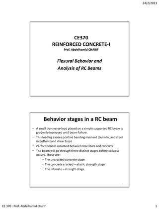
  • 1. 24/2/2013 CE 370 : Prof. Abdelhamid Charif 1 CE370 REINFORCED CONCRETE-I Prof. Abdelhamid CHARIF Flexural Behavior and Analysis of RC Beams Behavior stages in a RC beam • A small transverse load placed on a simply supported RC beam is gradually increased until beam failure. • This loading causes positive bending moment (tension, and steel in bottom) and shear force • Perfect bond is assumed between steel bars and concrete • The beam will go through three distinct stages before collapse occurs. These are: • The uncracked concrete stage • The concrete cracked – elastic strength stage • The ultimate – strength stage. 2
  • 2. 24/2/2013 CE 370 : Prof. Abdelhamid Charif 2 3 Simply supported beam under uniform load 4 Basic Assumptions in Flexure theory of RC Members 1. Plane sections before bending remain plane after bending. This assumption has been experimentally verified for all normal beams except deep beams (length to thickness ratio less than 3). 2. The strain in reinforcement equals to the strain in concrete at the same level (perfect bond, no slip). 1 & 2 imply that strain in reinforcement and concrete is directly proportional to the distance from N.A. 3. Tensile strength of concrete is neglected in flexural strength calculations (after cracking). 4. Stresses in concrete and reinforcement are calculated from strains using material stress-strain curves. Other assumptions will be made at ultimate state
  • 3. 24/2/2013 CE 370 : Prof. Abdelhamid Charif 3 5 Recall Concrete Stress-Strain Curve Compression: For a stress less or equal to 50% of fc’ , the curve is almost linear. Tension: Strength very small and curve assumed linear. 6 Recall Steel Stress-Strain Curve (Large plastic deformations after yielding)       ysy ysss s f E f   when when gradesallfor 200000MPaEs 
  • 4. 24/2/2013 CE 370 : Prof. Abdelhamid Charif 4 Uncracked Concrete Stage • At small loads when the tensile stresses are less than the modulus of rupture, the entire cross section of the beam resists bending. • Standard bending theory can be used. • Compression develops on top side and tension on bottom (for positive moments. 7 • Neutral axis passes through centroid • Moment of inertia of gross section is used 8 Uncracked Concrete Stage Strains and stresses
  • 5. 24/2/2013 CE 370 : Prof. Abdelhamid Charif 5 Concrete-Cracked – Elastic Stage • As load is increased, the modulus of rupture of the concrete is exceeded, and cracks begin to develop in bottom of the beam. • Cracking Moment: The moment at which tensile stress in the bottom of the beam equals the modulus of rupture (i.e. when cracks begin to form) is referred to as the cracking moment, Mcr • As load is further increased, cracks quickly spread closer to the neutral axis, which then begins to move upward. • Note: The cracks occur at all places along the beam where the actual moment is greater than the cracking moment. 9 Concrete-Cracked – Elastic Stage (contd.) • As concrete in the cracked zone cannot resist tensile stresses – the steel must do it. Perfect bond is still maintained. • This stage will continue as long as the compression stress in the top fibers is less than about one-half of the concrete compressive strength fc’ and as long as steel stress is less than its yield stress • In this stage the compressive stresses vary linearly with the distance from the neutral axis (straight line). 10 ratioModular with :pointsameat thestrainsEqual    n E E nnff E E ff E f E f c s cs c s cs s s c c sc 
  • 6. 24/2/2013 CE 370 : Prof. Abdelhamid Charif 6 • Service or Working Loads: Loads that actually occur when a structure is in normal service use. • Under working loads, moments develop which are considerably larger than the cracking moments. Obviously the tensile side of the beam will be cracked. • Under working loads, concrete compression stress is less than 50% of its strength and linear stress-strain variation is assumed. • Service loads and serviceability limit state correspond thus to the cracked elastic stage • To compute concrete and steel stresses in this range, the transformed-area method is used. 11 Cracked – Elastic Stage and Service Loads Beam Failure- Ultimate Strength Stage • As load is increased further, compressive stresses are greater than 0.5fc’, cracks and neutral axis move further upward . • Concrete compressive stresses begin to change appreciably from linear to curved, and reinforcing bars yield. 12
  • 7. 24/2/2013 CE 370 : Prof. Abdelhamid Charif 7 Moment Curvature Diagram • From the measured compressive strain in concrete and tensile strain in steel, the relationship between the bending moment and the curvature can be tracked up to failure. 13 dy y sc         ntaanglessmallVery NAfromdistancesomeatfiberbeamainstrain curvatureorsectionbeamtheofchangeAngle   y s c d  • Bending moments cause curvatures (rotations). • Curvature more objective than deflection as bending deformation. 14 Typical Moment Curvature Diagram for a Reinforced Concrete Beam There are three different stages in the curve : OC – CY - YF
  • 8. 24/2/2013 CE 370 : Prof. Abdelhamid Charif 8 15 Moment Curvature Diagram 1. First stage is for moments less than the cracking moment Mcr . The entire beam cross section is available to resist bending. The relationship is quasi-linear. 2. When the moment is increased beyond Mcr, the slope of the curve decreases as the cracked beam is not as stiff as in the initial stage. The diagram will still follow a straight line from Mcr to the point where steel is stressed to its yield point. 15 3. After steel yields, the beam has very little additional moment capacity, and only a small additional load is required to substantially increase rotations and deflections. The slope of the diagram is now almost flat. Bending stress in an Uncracked Beam • Steel area is small (usually 2% or less), and its effect on beam properties is negligible as long as the beam is uncracked • The bending stress in such a beam can be obtained based on the gross properties of the beam’s cross section. • The neutral axis coincides with the centroid • The stress in the concrete at a distance y from the neutral axis of the cross section can be determined from the following flexure formula: 16 section.crossgrosstheofinertiaofMoment sectiontheofmomentBending    g cr g I MM I My f
  • 9. 24/2/2013 CE 370 : Prof. Abdelhamid Charif 9 Cracking Moment 17 section.crosstheofinertiaofmomentGross momentBending    g g I M I My f t gr cr g tcr r cr t y If M I yM f fff yy    :Thus 9.5.2.3)sectionSBC/(ACI0.7ruptureofModulus fibertensionextremetoaxiscentroidalfromdistance Substitute ' Example 1: Uncracked section • Assuming concrete is uncracked, compute bending stresses in extreme fibers of the section below for a bending moment of 34 kN.m. fc’ = 30 MPa. • To check that the section is uncracked, first determine the cracking moment of the section. 18 375 450 300 283 All dimensions in mm
  • 10. 24/2/2013 CE 370 : Prof. Abdelhamid Charif 10 19 Solution of Example 1 uncrackedissectionthekN.m,34.0At kN.m8.38 N.mm108.38 225 1028.283.3 :)(MomentCracking mm1028.2450300 12 1 12 1 MPa83.3307.07.0 :ruptureofModulus 6 9 4933 '        M M y If M M bhI ff cr t gr cr cr g cr 19 375 450 300 283 Solution of Example 1 (continued) 20 uncracked.wellissectionThe MPa83.3307.07.0ruptureofModulus MPa35.3 1028.2 225)1034( 225 2 :fibersextremetwoAt the mm1028.2450300 12 1 12 1 :StressesBending ' 9 6 4933          r cr g g g ff ff I My f mm h y bhI I My f An uncracked beam is assumed to be homogeneous with neutral axis passing through the centroid of the beam section. Bending stress is given by the standard flexural equation. 375 450 300 283
  • 11. 24/2/2013 CE 370 : Prof. Abdelhamid Charif 11 Calculation of elastics stresses in cracked sections • When bending moment is sufficiently large to cause tensile stress in the extreme fibers , greater than the modulus of rupture, it is assumed that all of the concrete on the tensile side of the beam is cracked and must be neglected in the flexure calculations. • Cracking of the beam does not necessarily mean that the beam is going to fail. The reinforcing bars on the tension side begin to pick up the tension caused by the applied moment. • Assumption of perfect bond is made between reinforcing bars and concrete. Thus the strain in the concrete and in the steel will be the same at equal distances from the neutral axis. • Although the strains in the two materials at a particular point are the same, their stresses can not be the same as they have different values of elastic modulus. 21 Modular Ratio (n) 22 steelofthattimesbewillconcreterequiredofArea required?bewilltwotheofareaswhatconcreteorsteelbyresistedbetoisforceIf with nnAA n A A A F n A F nff F E E nnfff E E f E f E f sc s c cs cs c s csc c s s s s c c sc     Definition: The ratio of the steel modulus to the concrete modulus is called the modular ratio. If the modular ratio for a beam is 10, stress in steel will be 10 times the stress in concrete at the same distance from the neutral axis. Otherwise: when n = 10, 500 mm2 of steel will carry the same total force as 5000 mm2 of concrete. At the same point, steel and concrete strains are equal and the stresses are proportional to their modulus of elasticity.
  • 12. 24/2/2013 CE 370 : Prof. Abdelhamid Charif 12 Transformed Area Method • When the steel area As is replaced with an equivalent area of fictitious concrete (nAs), which supposedly can resist tension, the area is referred to as the transformed area. • As the transformed area is of concrete only, it can be analyzed by the usual methods for elastic homogeneous beams. 23 Tensile concrete is ignored Tensile steel area As replaced by equivalent concrete area nAs N.A. cf sA n fs snA Steps in transformed area method 1. Locate the neutral axis: – Assume it is located a distance x from the compression surface of the beam. – Equate the first moment of the compression area of the beam cross section about the neutral axis to the first moment of the tensile area about the neutral axis. – Solve the resulting quadratic equation. 2. Calculate the moment of inertia of the transformed section wit respect to the neutral axis. 3. Compute the stresses in the concrete and the steel with the flexure formula ( f = My/I ). 24
  • 13. 24/2/2013 CE 370 : Prof. Abdelhamid Charif 13 Example 2: Transformed Area Method • (a) Calculate the bending stresses in the beam shown below using the transformed area method • fc’ = 20 MPa, n = 9 and M = 95 kN.m • (b) Determine the allowable resisting moment of the beam, if the allowable stresses are : fac = 10 MPa and fas = 140 MPa 25 425 500 300 283 All dimensions in mm 26 Solution: 425 500 300 )1846( 283   sA All dimensions in mm 300 425 x )425( x 2 mm16614snA 49 2323 2 22 22 mm10571.1 168.5)(425(16614)168.5300 3 1 )(425)(168.5300 3 1 :axis)neutral(aboutInertiaofMoment mm5.168issolutionPositive 84.44778.200559470734)76.110( 04707376.1100706095016614150 166147060950150)425(16614150)425( 2 )(300 :)isfibertopfromdepthaxis(neutralaxisneutralaboutmomentsfirstTaking            I xnAI x xxxx xxxxxnA x x x s s
  • 14. 24/2/2013 CE 370 : Prof. Abdelhamid Charif 14 27 MPa6.139 10571.1 5.256)1095( 9 :mm)256.5168.5-425(levelSteel MPa2.10 10571.1 5.168)1095( :mm)168.5(ncompressioExtreme :StressesBending 9 6 9 6                 I My nf I My n f fy I My fy I My f s s c c kN.m2.95N.mm102.95 5.2569 10571.1140)/( mm256.5168.5-425:levelsteelAt the :steelintensionallowabletoingcorrespondmomentAllowable kN.m2.93N.mm102.93 5.168 10571.110 :concreteinncompressioallowabletoingcorrespondmomentAllowable :momentresistingAllowable(b) 6 9 6 9          ny If y Inf M y y If M y If M I yM f asas as ac ac allowable allowable allowable allowable Solution – Cont. 28 Concrete and steel will reach their permissible stresses at these moments respectively. Discussion: Concrete and steel will not reach their maximum allowable stresses at exactly the same bending moments. The resisting moment of the section is 93.2 kNm (the smallest) because if that value is exceeded, concrete becomes overstressed even though the steel stress is less than its allowable stress. kN.m2.95 kN.m2.93 :momentsresistingAllowable   as ac M M Solution – Cont.
  • 15. 24/2/2013 CE 370 : Prof. Abdelhamid Charif 15 2929 d h b sA b h x )( xd  snA I xdM nfxdy I Mx fxy xnA bx Ix xnAdnA bx xdnA bx xdnA x x x s c s ssss )( :)(stresstensionSteel :)(stressncompressioconcreteTop )(d)( 3 :NA)(aboutinertiaofMomentforSolve 0 2 )( 2 )( 2 )(b :)isfibertopfromdepthaxis(neutralaxisneutralaboutmomentsFirst 2 3 22           Steps for a General Rectangular Section Ultimate State and Nominal Flexural Moment • After concrete compression stresses exceed about 50% of fc’, they no longer vary linearly. The variation is rather nonlinear as shown in Figure (b) 30 d yf b sA c (a) Beam (b) Actual compression stress variation Neutral axis depth is now noted c
  • 16. 24/2/2013 CE 370 : Prof. Abdelhamid Charif 16 31 The ultimate flexural moment capacity is called “Nominal” moment and is noted Mn. It is derived using this assumption: The curved compression diagram can be replaced by a rectangular one with a constant stress of 0.85 fc’ (Whitney). The Whitney rectangular stress block of depth “a” is assumed to have the same area and same centre of gravity as the curved diagram (generating the same force and the same moment). d yf b sA c ca 1 abfC c ' 85.0 ' 85.0 cf (a) Beam (b) Actual block of compression stress (c) Whitney block of compression stress ys fAT  Ultimate State and Nominal Flexural Moment 32 Apart from the previous standard assumptions (sections remain plane after bending, perfect bond between concrete and steel bars, concrete tensile strength ignored), two other assumptions are added in the ultimate stage: • Concrete is assumed to fail (crush) when its compressive strain at the extreme fiber reaches its ultimate value εcu = 0.003 • The nonlinear compressive stress block for concrete is replaced by an equivalent rectangular one with constant stress of 0.85 fc’ and a depth a = 1 c Additional assumptions at ultimate state        MPafforf MPaffor cc c 3065.0,008.009.1Max 3085.0 1 1 shall not be smaller than 0.65
  • 17. 24/2/2013 CE 370 : Prof. Abdelhamid Charif 17 33 Factor 1 to account for skewed shape of compression stress block Question: Why does 1 vary (reduced for fc’ > 30 MPa) ?        MPafforf MPaffor cc c 3065.0,008.009.1Max 3085.0 1 34 Variation of coefficient 1 Observe skewed shape of compression stress-strain curves for higher strength The shapes of the stress- strain curves for high strength concrete are skewed. This shifts the centroid of the area (below the curve) closer to the origin, and thus reduces the length of the equivalent rectangle. Thus 1 must be smaller for high strength concrete.
  • 18. 24/2/2013 CE 370 : Prof. Abdelhamid Charif 18 35 There are three types of flexural failure of a structural member: 1. Steel reaches its yield strength before concrete reaches its ultimate strain of 0.003 (Under-reinforced section) 2. Steel reaches yield limit at the same time as concrete reaches its ultimate strain (Balanced section). 3. Concrete fails before the yield of steel, in the case of presence of a high percentage of steel in the section (Over-reinforced section). Types of ultimate flexural failure 36 Steel reaches its yield strength before concrete reaches its ultimate strain. Large deformations occur before concrete crushing. Failure is ductile. After yielding, the steel tensile force remains constant. To maintain an equal equilibrating concrete compression force, the neutral axis is shifted up. Cracks will also progress upwards. Under-reinforced section
  • 19. 24/2/2013 CE 370 : Prof. Abdelhamid Charif 19 37 Steel reaches its yield limit at the same time as concrete reaches the ultimate strain. Failure is sudden and brittle Balanced section 38 Concrete crushes before the yield of steel, due to the presence of a high percentage of steel in the section. Failure is very sudden and brittle Over-reinforced section
  • 20. 24/2/2013 CE 370 : Prof. Abdelhamid Charif 20 39 Moment-Curvature for various steel areas (Increasing steel area reduces ductility) Types of flexural failure • Brittle failures are very dangerous and must be avoided. • All codes of practice (ACI, SBC, …) require beams to be designed as under-reinforced to ensure ductile behavior. • In fact SBC and ACI codes require more ductility than just under reinforced. 40