Lec04 Analysis of Rectangular RC Beams (Reinforced Concrete Design I & Prof. Abdelhamid Charif)
•
8 likes•1,303 views

Lec04 Analysis of Rectangular RC Beams (Reinforced Concrete Design I & Prof. Abdelhamid Charif)

Recommended
Recommended
More Related Content
What's hot
What's hot (20)
Similar to Lec04 Analysis of Rectangular RC Beams (Reinforced Concrete Design I & Prof. Abdelhamid Charif)
Similar to Lec04 Analysis of Rectangular RC Beams (Reinforced Concrete Design I & Prof. Abdelhamid Charif) (20)
More from Hossam Shafiq II
More from Hossam Shafiq II (20)
Recently uploaded
Recently uploaded (20)
Lec04 Analysis of Rectangular RC Beams (Reinforced Concrete Design I & Prof. Abdelhamid Charif)
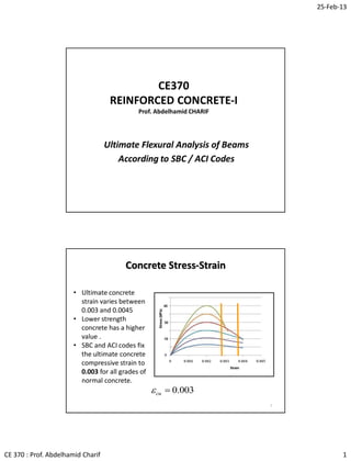
- 1. 25-Feb-13 CE 370 : Prof. Abdelhamid Charif 1 CE370 REINFORCED CONCRETE-I Prof. Abdelhamid CHARIF Ultimate Flexural Analysis of Beams According to SBC / ACI Codes Concrete Stress-Strain 2 • Ultimate concrete strain varies between 0.003 and 0.0045 • Lower strength concrete has a higher value . • SBC and ACI codes fix the ultimate concrete compressive strain to 0.003 for all grades of normal concrete. 003.0cu
- 2. 25-Feb-13 CE 370 : Prof. Abdelhamid Charif 2 Stress Distribution at Ultimate Stage 3 d b sA (a) Section (b) Strain (d) Whitney’s assumed stress N.A. 003.0 s (c) Actual stress ca 1 abfC c ' 85.0 ' 85.0 cf ss fAT c sf ' cf Whitney replaced the curved stress block with an equivalent rectangular one having the same area and the same centroid. 65.0,008.009.1Max:MPa30For 85.0:MPa30For depthand850ofstressConstant 1 1 1 ' c ' c ' c ' c ff f caf. Nominal and Design Flexural Strength 4 d b sA N.A. c ca 1 abfC c ' 85.0 ' 85.0 cf ss fAT un MM Theoretical or Nominal Flexural Moment (Strength) noted : Mn Design or Usable Flexural Moment (Strength) noted : Mn Design Moment = Nominal Moment X Strength Reduction Factor Design moment must be equal to or greater than ultimate moment caused by factored loads:
- 3. 25-Feb-13 CE 370 : Prof. Abdelhamid Charif 3 5 • In all structural members, moments are computed about the centroid of the gross section. • For beams with no external force, the two internal forces are equal C = T. Thus : Moment = Moment of a force couple • Moment = T x Lever arm = C x Lever arm. Moments in RC Beams d b sA N.A. c ca 1 abfC c ' 85.0 ' 85.0 cf ss fAT 22 a dC a dTMn Tension steel ratio for RC beams • In reinforced concrete beams subjected to bending, it is common to express the tension steel amount using either the area As or the corresponding steel ratio (no unit) defined as: 6 bdA bd A s s Where b and d are the width of the section and the depth of the tension steel respectively. Note that the steel ratio in beams is not related to the gross section area as in columns.
- 4. 25-Feb-13 CE 370 : Prof. Abdelhamid Charif 4 Minimum Steel Ratio • The applied bending moment (Mu) may sometimes be so small that an unreinforced concrete section can theoretically resist it. • However, the section will fail immediately when a crack occurs. • The cracks may occur even if the member is unloaded because of shrinkage effects. This type of failure is brittle with no warning. • To prevent such a possibility, codes specify a minimum amount of reinforcement that must be satisfied at every section of flexural members. 7 yy c w s w w yy c s ff f db A b db ff f A 4.1 , 4 Max beamofwidthwebwhere 4.1 , 4 Max ' min min, min ' min, Section Types Based on Ductility 8 memberscontrollednCompressioorBrittleCalled yieldssteelbeforecrushesConcrete :)reinforced-(overfailureBrittle memberscontrolledTensionorDuctileCalled crushesconcretebeforeyieldsSteel :)reinforced-(underfailureDuctile members/sectionsBalancedCalled crushesconcretewhenyieldreachesSteel :sectionBalanced b b b
- 5. 25-Feb-13 CE 370 : Prof. Abdelhamid Charif 5 Balanced Section A section that has a steel ratio such that the steel reaches yield strain εy (= fy /Es) when the concrete strain attains the ultimate value of 0.003. 9 d b sA c 003.0 cd syy Ef / b s bd A :sectionbalancedFor ratioStee Brittle Members Members whose steel tensile strain εt at the extreme bottom layer is equal to or less than εy when the concrete strain reaches 0.003 are called compression-controlled – considered to be brittle by SBC and ACI. Concrete crushes before steel yields. Deflections are small and there is little warning of failure. 10 d b sA c 003.0 cd yt ts t s εε ε ε :onlylayeroneofIn layerbottomextremeatStrain: centroidsteelat tensionStrain: :usedNotations
- 6. 25-Feb-13 CE 370 : Prof. Abdelhamid Charif 6 Ductile members Members whose steel tensile strain εt at the extreme bottom layer is equal to greater than 0.005 (more than yield strain) when the concrete strain reaches 0.003 are called tension- controlled – considered to be fully ductile by SBC and ACI Steel yields well before concrete crushes Deflections are large and there is warning before failure 11 d b sA c 003.0 cd 005.0t 12 Transition Region Members with steel strains between y and 0.005 are in a transition region (y < εt < 0.005) 12 d b sA c 003.0 cd 005.0 ty
- 7. 25-Feb-13 CE 370 : Prof. Abdelhamid Charif 7 Balanced Steel Ratio 13 d b sA N.A. 003.0 yt ca 1 abfC c ' 85.0 ' 85.0 cf ys fAT c At the balanced point, steel reaches its yield strain at the same time as concrete reaches its ultimate strain of 0.003 The corresponding steel ratio is called balanced steel ratio ρb The balanced steel ratio is obtained by equating two different expressions of the neutral axis depth. Balanced Steel Ratio 14 (b) s y y E f d c d c 003.0 003.0 003.0 003.0 :ianglessimilar trFrom (a)' c y s ' c y yys ' c f df c a c bd A f df a bdffAabf. TC 11 85.0 with, 85.0 850 :mequilibriuForce d b sA 003.0 s y y E f ca 1 abfC c ' 85.0 ' 85.0 cf ys fAT c
- 8. 25-Feb-13 CE 370 : Prof. Abdelhamid Charif 8 Balanced Steel Ratio 15 yy ' c yy ' c b yy ' c yb s s y ' c yb ff f f f fff f E E f d f df 600 60085.0 003.0 003.085.0 600 600 2000000 003.0 003.0 85.0 MPa)102( 003.0 003.0 85.0 11 1 6 1 d b sA 003.0 s y y E f ca 1 abfC c ' 85.0 ' 85.0 cf ys fAT c (b) (a) s y ' c y E f d c f df c 003.0 003.0 85.0 1 Maximum Steel Ratio 16 (b)dc d c 8 3 8 3 005.0003.0 003.0 :ianglessimilar trFrom d b sA 003.0 005.0 ca 1 abfC c ' 85.0 ' 85.0 cf ys fAT c In order to have the members ductile enough, steel tensile strain should not be less than 0.005 (when concrete strain reaches 0.003).. This corresponds to the maximum tension steel ratio. It is again obtained by equating two expressions of the neutral axis depth. (a)' c y s ' c y yys ' c f df c a c bd A f df a bdffAabf. TC 11 85.0 with, 85.0 850 :mequilibriuForce
- 9. 25-Feb-13 CE 370 : Prof. Abdelhamid Charif 9 Maximum Steel Ratio 17 max 1 max 1 max 1 max 005.0 8 385.0 8 385.0 8 3 85.0 t y ' c y ' c ' c y ε f f f fd f df d b sA 003.0 005.0 ca 1 abfC c ' 85.0 ' 85.0 cf ys fAT c (b) (a) dc f df c ' c y 8 3 85.0 1 18 b y y b y ' c yy ' c b f f f f 008.0 003.0 3 8 003.0 003.0 8 385.0 003.0 003.085.0 :ratiostwofor thesexpressionpreviousUsing max max 1 max 1 d 003.0 max 005.0 t maxc 003.0 b yt bc Maximum and Balanced Steel Ratios max max max 5686.1 6375.0 8 1.5 008.0 0051.0 0021.0:420For b b bb yy MPaf
- 10. 25-Feb-13 CE 370 : Prof. Abdelhamid Charif 10 Tension steel strain check Maximum steel ratio check Neutral axis depth check • Ensuring that steel ratio is less than or equal to the maximum limit is equivalent to checking that tensile steel strain is equal to or greater than 0.005 • This is also equivalent to checking that neutral axis depth is limited such (using similar triangles): 19 dc d c d c t t t 375.0005.0 375.0 8 3 005.0 003.0 003.0 max d 003.0 005.0t c • These three checks are equivalent. • The tension steel strain is sufficient and more informative about steel strain values. • In case of many tension steel layers, the maximum steel ratio check and the neutral axis depth check may be misleading. • It is therefore recommended to always use steel strain check and discard the other two checks. 20 Tension steel strain check Maximum steel ratio check Neutral axis depth check dct 375.0005.0 max
- 11. 25-Feb-13 CE 370 : Prof. Abdelhamid Charif 11 Strength Reduction Factors Strength reduction factors () account for : • Uncertainties in material strength • Approximations in analysis and simplifications in equations • Variations in dimensions and in placement of reinforcement • Type of failure (Tension-control or compression-control) Typical values of : • Tension controlled sections : = 0.90 • Compression members and Tied Columns : = 0.65 • Compression Spiral Columns : = 0.70 • Flexure and compression (transition) : = 0.65 (0.70) to 0.90 • Shear and torsion : = 0.75 • Bearing on concrete : = 0.65 21 22 Variation of with Tensile Steel Strain The strength reduction factor varies in the transition region. Beams must have a tensile steel strain of at least 0.005 for SBC code (0.004 for ACI code).
- 12. 25-Feb-13 CE 370 : Prof. Abdelhamid Charif 12 23 Types of Beams Analysis of RC Beams Determination of moment capacity 24 • Analysis of existing RC beams is somewhat different from the analysis and check involved in the design stage. • For new beams to be designed, all code provisions must be enforced. If any condition is not satisfied, the design must be repeated. • For existing beams, the analysis must be completed and any deficiencies reported. If for instance the section is not tension controlled or not satisfying minimum steel condition, its nominal and design moments must still be determined using appropriate strength reduction factors.
- 13. 25-Feb-13 CE 370 : Prof. Abdelhamid Charif 13 25 Values of strength reduction factor for beams • Tension control condition is required in all beam design problems, with a strength reduction factor ( = 0.90) • In analysis problems however, other cases may be met. • The value of the strength reduction factor depends on the tensile steel strain at the extreme (bottom) layer: 65.0:controlnCompressioIf 005.0 25.065.0:zoneTransition005.0If 90.0:controlTension005.0If yt y yt ty t 26 d b sA N.A. c ca 1 abfC c ' 85.0 ' 85.0 cf ss fAT The main difficulty in analysis problems is that it is not known whether steel has yielded or not. Existing beams may have been designed as over reinforced with steel not yielding at failure. Yielding case is much simpler as the steel stress is then known and constant fy It is usually first assumed that steel has yielded and if turns out that it has not, then a different method is used. Nominal Moment in RC Beams
- 14. 25-Feb-13 CE 370 : Prof. Abdelhamid Charif 14 27 22 :momentNominal :continueyiedling,OK:If0030ianglesSimilar tr 850 850 1 a dfAM a dTM ε c cd .ε a c bf. fA afAabf.TC ysnn ytt ' c ys ys ' c Nominal Moment – Tension Steel Yielding d b sA (a) Section (b) Strains (c) Stresses / Forces N.A. 003.0 yt ca 1 abfC c ' 85.0 ' 85.0 cf ys fAT c 28 0600600850 )(600850600850 :givesand850850 600)200000( 2 1 2 11 1 dAcAcbf. cdAcbf. c cd Acbf. TCcbf.abf.C c cd ATMPaE ss ' c s ' cs ' c ' c ' c ss Nominal Moment – Tension Steel Not Yielding c cd .EAT c cd EAfAT ss t tssss yt 0030 003.0 :ianglesSimilar tr :ThenIf d b sA N.A. 003.0 yt ca 1 abfC c ' 85.0 ' 85.0 cf tssss EAfAT c (a) Section (b) Strains (c) Stresses / Forces
- 15. 25-Feb-13 CE 370 : Prof. Abdelhamid Charif 15 29 Nominal Moment – Tension Steel Not Yielding 22 :momentNominal :yieldednothassteelionthat tensConfirm 600and003.0,:Deduce 1 4 1 2 :issolutionPositive solutions.ith twoequation wQuadratic 85.0 600 with0 0600600850 1 1 ' 2 2 1 a dfAM a dTM c cd εEf c cd ca P dP c bf A PPdPcc dAcAcbf. ssnn yt tsst c s ss ' c Analysis of a rectangular RC section Steps in determining design moment 30 6Goto 2 :yieldingOKIf4/ 003.0strainsteelTensile/3 and 85.0 yieldingsteelAssume/2 :Check 4.1 , 4 Max, :valuesratiosteelminimumandactualCompute1/ t 1 min ' min a dfAM c cd a c bf fA a ff f bd A ysny t ' c ys yy cs
- 16. 25-Feb-13 CE 370 : Prof. Abdelhamid Charif 16 Steps in determining design moment – Cont. 31 n t yt y yt ty t ssnn tssytt c s yt M ε ε. εε ε a dfAM a dTM εEf c cd ca bf A P P dP c ismomentDesign/7 SBC)byRejected,controllednNot tensio:005.0(If 0.65:controlnCompressioIf 0050 25.065.0:zoneionIn transit005.0If 0.90:controlTension005.0If :factorreductionSrength6/ 22 :momentNominal :check003.0, 85.0 600 with,1 4 1 2 :yieldingnotSteel:If5/ 1 1 ' Problem 1 32 85.0MPa30MPa420 1 ' cy ff 600 375 284 75 675 OK 00333.000333.0,00326.0Max 420 4.1 , 4204 30 Max 4.1 , 4 Max 0109.0 600375 0.2463 :ratioSteel 0.246382 4 4:areaSteel min min ' min 22 yy c s s ff f bd A mmA Determine the nominal and design moments of the beam section shown.
- 17. 25-Feb-13 CE 370 : Prof. Abdelhamid Charif 17 33 mm3.127 85.0 2.108 mm2.108 3753085.0 4200.2463 85.0 yiedingsteelAssume 1 a c a bf fA a ff ' c ys ys 0.90 controltensionandyieldingSteel 005.00111.0 0111.0 3.127 3.127600 003.0 003.0 yt t t c cd kN.m508.24 kN.m71.5649.0:momentDesign kN.m71.564N.mm1071.564 2 2.108 6004200.2463 22 6 n n n n ysn M M M M a dfA a dTM Solution 1 3.127 003.0 7.472 s 600 375 284 Problem 2 Determine the nominal and design moments of the beam section shown. fc’ = 20 MPa and fy = 420 MPa 34 525 600 mm350 283 OK 00333.000333.0,00266.0Max 420 4.1 , 4204 20 Max 4.1 , 4 Max 01005.0 525350 25.1847 :ratioSteel 25.184782 4 3:areaSteel min min ' min 22 yy c s s ff f bd A mmA
- 18. 25-Feb-13 CE 370 : Prof. Abdelhamid Charif 18 35 mkNM a dfAM MOK c cd mm a c n t ysn nyt t .03.3217.35690.0 control)(Tension90.0005.000726.0 kN.m7.356N.mm107.356 2 39.130 52542025.1847 2 :forContinue.assumedasyieldedhassteel0021.000726.0 00726.0 4.153 4.153525 003.0003.04.153 85.0 39.130 :yieldedhassteelCheck that 6 1 525 350 283 ca 1 abfC c ' 85.0 ' 85.0 cf ys fAT 2 a d Solution 2: Assume steel yielding mm39.130 3502085.0 42025.1847 85.0 25.184728 4 3 ' 22 a bf fA aTC mmA fATff c ys s ysysys Problem 3 Determine the nominal and design moments of the beam section shown. Same as previous problem but with one more steel bar. fc’ = 20 MPa and fy = 420 Mpa 36 OK 00333.000333.0,00266.0Max 420 4.1 , 4204 20 Max 4.1 , 4 Max 0134.0 525350 0.2463 :ratioSteel 0.246382 4 4:areaSteel min min ' min 22 yy c s s ff f bd A mmA 525 600 mm350 284
- 19. 25-Feb-13 CE 370 : Prof. Abdelhamid Charif 19 37mkNM a dfAM MOK c cd mm a c n t ty ysn nyt t .06.39616.453874.0 874.0 0021.0005.0 0021.00047.0 25.065.0 005.0 25.065.0:Transition005.00047.0 kN.m53.164N.mm1016.453 2 86.173 5254202463 2 :forContinue.assumedasyieldedhassteel0021.00047.0 0047.0 54.204 54.204525 003.0003.054.204 85.0 86.173 y y 6 1 Solution 3: Assume steel yielding :strainsteelCheck mm86.173 3502085.0 4200.2463 85.0 ' a bf fA aTC fATff c ys ysysyt 525 350 284 ca 1 abfC c ' 85.0 ' 85.0 cf ys fAT 2 a d Problem 4 • The reinforcement of 2945 mm2 is from six 25-mm bars which are arranged in two layers but are assembled (lumped) together in a single compact layer. 38 Determine the nominal and design moments of the beam section shown. fc’ = 20 MPa and fy = 420 MPa 510 250 2945 90 600 2 mm OK00333.000333.0,00266.0Max 420 4.1 , 4204 20 Max 4.1 , 4 Max 0231.0 510250 2945 :ratioSteel minmin ' min yy c s ff f bd A
- 20. 25-Feb-13 CE 370 : Prof. Abdelhamid Charif 20 39 mm4.342 85.0 04.291 mm04.291 2502085.0 4200.2945 85.0 yiedingsteelAssume 1 a c bf fA a ff ' c ys ys mmcammc cP bf A P P dP c c cd c s yt t 82.26455.31185.055.311 1 135.489 5104 1 2 135.489 135.489 85.02502085.0 2945600 85.0 600 with,1 4 1 2 yieldingNot0147.0 00147.0 4.342 4.342510 003.0003.0 1 1 ' Solution 4 510 250 2945 90 600 2 mm 40 kN.m.24762kN.m98.42465.0:momentDesign 0.65:controlnCompressio kN.m98.424N.mm1098.424 2 82.264 51018.3820.2945 22 6 n yt n ssn M M a dfA a dTM Solution 4 - Continued )(18.3820019109.0200000 yieldingNotOK0019109.0 55.311 55.311510 003.0003.0 82.26455.311 ytss yt fMPaEf c cd mmammc This beam is over reinforced (compression controlled) and is not allowed by SBC / ACI codes. The two steel layers were lumped at their centroid but lumping is allowed only if all layers are yielding. Non yielding with many layers can only be analyzed using the strain compatibility method described later.
- 21. 25-Feb-13 CE 370 : Prof. Abdelhamid Charif 21 41 Lumping of tension steel layers at centroid • If tension steel is arranged in two or more layers, these can be, in the calculations, replaced by a single steel area at their centroid. This Layer lumping (assembly) simplifies analysis and design equations. Standard beam design cannot in fact deal with more than one tension steel layer. • As layer strains are different, lumping is only justified if all tension layers have yielded (and have the same yield stress). • Tension steel depth d must therefore be computed at the centroid of the layers. • Yielding must be checked at the least tensioned layer with minimum depth dmin • It is therefore unsafe to check yielding at the centroid • Performing tension control check at the centroid is uneconomical. It should be performed at the most tensioned extreme bottom layer. 42 0.003 d dt c Depths Strains 005.0t yε min dmin s Lumping of tension steel layers at centroid 005.0 :layersMany 005.0:layerOne min t y t ε Required steel strain checks : ts ts ε ε min min :layersMany :layerOne centroidsteelAt tension:, layer(bottom)max.depthAt:, layerdepthminimumAt:, :usedNotations minmin s tt εd εd εd
- 22. 25-Feb-13 CE 370 : Prof. Abdelhamid Charif 22 Determine design moment for the shown section with six 20-mm bars in two layers. Bar / layer spacing is 30 mm. 43 MPa420andMPa20 y ' c ff 250 206 650 Problem 5 mm dd d mmdd dSddd mmdd d dhdd bl t b st 565 2 :centroidatdepthsteelEffective 5402030590 :layerSecond 590 2 20 1004650 2 cover:layerbottomFirst :depthsSteel 21 min2 1min2 1 1 Solution 5 44 OK 00333.000333.0,00266.0Max 420 4.1 , 4204 20 Max 4.1 , 4 Max 0133.0 565250 96.1884 :ratioStee 96.188402 4 6:areaSteel min min ' min 22 yy c s s ff f bd A mmA 250 206 565 mm15.219 85.0 28.186 mm28.186 2502085.0 42096.1884 85.0 depthblockStress :steelofyieldingAssume 1 1 a cca bf fA a ' c ys
- 23. 25-Feb-13 CE 370 : Prof. Abdelhamid Charif 23 45 layer.steelbottomattestcontroltensionperformBetter controlled-nnot tensioissectionthecentroid,At the 005.00047.0 15.219 15.219565 003.0003.0 :centroidsteelatcheckStrain:Important 0.90controlTensionOKandyieldOK 005.000507.0 15.219 15.219590 003.0003.0 :layer)(bottomdepthmaximumatcheckcontrolTension 0021.00044.0 15.219 15.219540 003.0003.0 :depthminimumatstrainsteelofcheckYield min min c cd c cd OK c cd s y t t y Solution 5 Continued 46 kN.m20.363 kN.m56.3739.0:momentDesign kN.m56.373N.mm1056.373 2 28.186 56542096.1884 22 6 n n n ysn M M M a dfA a dTM Solution 5 Continued 15.219 003.0 0044.0 250 206 565 00507.0 0047.0 This example shows the importance (economy) of performing the tension control check at the extreme bottom layer of tension steel.
- 24. 25-Feb-13 CE 370 : Prof. Abdelhamid Charif 24 Determine the design moment for the shown section 47 MPa420andMPa27 y ' c ff Problem 6 mm dd d mmdd mmdd t 608 2 :centroidatdepthsteelEffective 580:layerSecond 636:layerbottomFirst 21 min2 1 OK00333.000333.0,00309.0Max 420 4.1 , 4204 27 Max 4.1 , 4 Max 0270.0 608300 0.4926 0.492682 4 8 minmin ' min 22 yy c s s ff f bd A mmA 300 288 700 Solution 6 (assume steel yielding) 48 ys ty t t y ' c ys c cd c cd c cd a c bf fA a 00216.0 53.353 53.353608 003.0003.0:straincentroidSteel:Important ionIn transit005.000240.0 53.353 53.353636 003.0003.0 :layer)(bottomdepthmaximumatcheckcontrolTension justifiednotLumpingyieldingNo00192.0 53.353 53.353580 003.0 003.0:depthminimumatstrainsteelofcheckYield mm53.353mm50.300 3002785.0 4200.4926 85.0 depthBlock min min min 1 Steel is not yielding at the minimum depth layer although it is yielding at the centroid. Lumping is therefore unjustified and would unsafely deliver a higher moment capacity. This example proves that it is unsafe to perform the yield check at the centroid.
- 25. 25-Feb-13 CE 370 : Prof. Abdelhamid Charif 25 49 mkNM a dfAM n ysn .2.640kN.m05.947676.0:momentDesign 676.0 0021.0005.0 0021.00024.0 25.065.0transitionIn005.000240.0 kN.m05.947N.mm1005.947 2 5.300 6084200.4926 2 tt 6 Solution 6 Continued This example shows the importance (safety) of performing the steel yield check at the least tensioned steel layer (with minimum depth). The unsafe (over estimated) moment capacity would be as : This result is of course unsafely false because of an unjustified use of layer lumping. The exact nominal moment obtained using the strain compatibility method is 935.76 kN.m 53.353 003.0 00192.0 300 288 608 00240.0 00216.0 Determine design moment for the shown section (shallow beam very popular in KSA) with nine 20-mm bars in three layers. Layer spacing is equal to 30 mm. It is obvious this is not a correct bar arrangement as the beam width can accommodate more than three bars. However design and / or execution errors are unfortunately always possible. 50 0026.0and 802.065.0,008.009.1Max MPa520andMPa36 y 1 ' c y ' c f ff Problem 7 – Special and Important 500 209 380
- 26. 25-Feb-13 CE 370 : Prof. Abdelhamid Charif 26 51 Solution of Problem 7 mmd ddd d mmdd dSddd mmd dSdd mmdd d dhdd bl bl t b st 270 3 :centroidatdepthsteelEffective 2202030270 :layerThird 2702030320 :layerSecond 320 2 20 1004380 2 cover:layerbottomFirst :depthsSteel 2 321 min3 2min3 2 12 1 1 500 209 380 Solution 7 52 OK 00284.000269.0,00284.0Max 520 4.1 , 5204 35 Max 4.1 , 4 Max 0209.0 270500 4.2827 :ratioStee 4.282702 4 9:areaSteel min min ' min 22 yy c s s ff f bd A mmA mm81.119 802.0 09.96 mm09.96 5003685.0 5204.2827 85.0 depthblockStress:yieldingsteelAssume 1 a ca bf fA a ' c ys 500 209 380
- 27. 25-Feb-13 CE 370 : Prof. Abdelhamid Charif 27 53 ys t t t y c cd c cd c cd 00376.0 81.119 81.119270 003.0003.0 :centroidsteelatcheckStrain:Important ControlTensionOK005.000501.0 00501.0 81.119 81.119320 003.0003.0 :layer)(bottomdepthmaximumatcheckcontrolTension OKNOTCheckYield0026.000251.0 00251.0 81.119 81.119220 003.0003.0 :depthminimumatstrainsteelofcheckYield min min min Solution 7 Continued 54 The section is tension-controlled (accepted by SBC) as the bottom strain is just greater than the 0.005 limit. However, although steel has yielded at the centroid, the strain in the upper layer is less than the yield limit. The previous calculations, based on the assumption of yielding of all steel, are thus incorrect and unsafe. It is therefore more exact and safer to perform the yield check at the upper layer with minimum depth. ys t y 00376.0 ControlTensionOK 005.000501.0 OKNOTYield 0026.000251.0min 8.119 003.0 00251.0 500 209 270 00501.0 00376.0 Solution 7 Continued
- 28. 25-Feb-13 CE 370 : Prof. Abdelhamid Charif 28 55 kN.m70.293kN.m33.3269.0:momentDesign kN.m33.326N.mm1033.326 2 09.96 2705204.2827 22 6 n n ysn M M a dfA a dTM Solution 7 Continued This example shows the importance (safety) of performing the tension control check at the upper layer of tension steel. This incorrect solution for the nominal and design moments is : 8.119 003.0 00251.0 500 209 270 00501.0 00376.0 The exact solution based on the actual strain in every layer, would deliver lower values of moments. As the strain in the upper layer is close to yield, the exact solution should be just slightly lower. 56 Strain Compatibility Solution 7 • The strain compatibility method is a very powerful analysis tool for complex situations, with many steel layers. • It is based on the linear variation of strains resulting from the assumption of sections remaining plane after bending. • The stress at any level or layer is related to the strain through the material model (stress-strain curve). No layer lumping is used. • All strains are expressed in terms of the neutral axis depth c which is the main problem unknown. c 003.0 3s 500b 2033 1s 2s c cd i i si 003.0 :layerAt
- 29. 25-Feb-13 CE 370 : Prof. Abdelhamid Charif 29 57 Strain Compatibility Solution 7 – Cont. • The method is more effective if a good initial assumption is made about yielding (or not) of the various steel layers. • It is reasonable to assume that at failure the bottom two layers have yielded and that the third is in the elastic range (stress proportional to strain through Young’s modulus). The strains and forces are therefore as shown in the figure. c 003.0 ys 3 500 2033 ys 1 ys 2 ca 1 ' 85.0 cf 33 sss EA ys fA1 ys fA 2 abfc ' 85.0 Section Strains Forcesc cdi si 003.0 58 Strain Compatibility Solution 7 – Cont. • The two unknown forces are the concrete compression and the tension in the third layer. They are both expressed in terms of the neutral axis depth (using 200000 MPa for steel modulus) : c cd A c cd EAEATcbfabfC sssssssccc 3 3 3 33331 '' 600003.085.085.0 c 003.0 ys 3 500 2033 ys 1 ys 2 ca 1 ' 85.0 cf 33 sss EA ys fA1 ys fA 2 abfc ' 85.0 Section Strains Forcesc cdi si 003.0
- 30. 25-Feb-13 CE 370 : Prof. Abdelhamid Charif 30 59 Strain Compatibility Solution 7 – Cont. • We now express the force equilibrium : c cd AEATcbfabfC sssssccc 3 33331 '' 60085.085.0 c cd AfAfAcbfTTTC sysyscsssc 3 3211 ' 321 60085.0 • Remark: If more than one layer has not yielded, its strain, stress and force are again expressed in terms of the neutral axis depth (c) and the latter will remain the only unknown in the final equilibrium equation. • We multiply by c and after assembling, we obtain a quadratic equation : 060060085.0 60085.0 33321 2 1 ' 3321 2 1 ' dAcAfAfAcbf cdAcfAfAcbf ssysysc sysysc 60 Strain Compatibility Solution 7 – Cont. • Substitution with the given data leads to : 002546.000381.000507.0003.0 0.119:issolutionPositive 2.20463.41696 0632.10138795.33 012440709632.4146906.12270 321 2 2 sss i si c cd mmc cc cc mmdmmdmmd mmAAA mmbMPafMPaf dAcAfAfAcbf sss yc ssysysc 220270320 478.942 802.050052036 060060085.0 321 2 331 1 ' 33321 2 1 '
- 31. 25-Feb-13 CE 370 : Prof. Abdelhamid Charif 31 61 Strain Compatibility Solution 7 – Cont. • The assumed steel strain conditions are confirmed. The third layer has not reached the yield limit but is very close to it. • If the assumed yielding (or not) condition is violated in any layer, then new calculations must be carried out. • The strain in the bottom layer confirms that the section is tension controlled : • Substitution gives the forces, which must satisfy equilibrium. 002546.000381.000507.00.119 321 sssmmc kNTkNTTkNC c cd ATfATfATcbfC sssc ssyssysscc 95.47909.49020.1460 60085.0 321 3 3322111 ' • Equilibrium is checked. The sum of the steel tensile forces is equal to concrete compression force. 62 Strain Compatibility Solution 7 – Cont. • The nominal moment is better determined as the moment of the steel tensile forces about the compression centroid. • Using kN and meter units : ' 85.0 cf 33 sss EA ys fA1 ys fA 2 abfc ' 85.0 44.95 1ca ' 85.0 cf 95.479 09.490 09.490 20.1460 mkNMmkNM M a dT a dT a dTM nn n sssn .55.29206.32590.0.06.325 2 09544.0 22.095.479 2 09544.0 27.009.490 2 09544.0 32.009.490 222 332211 • This exact solution is less than but close to the previous false one because the third layer was very close to yielding. Despite non yielding of the top layer, the section is still tension controlled.
- 32. 25-Feb-13 CE 370 : Prof. Abdelhamid Charif 32 6363 Lumping of many tension steel layers Caution • Lumping all steel layers at the centroid may only be valid for normal beams not exceeding three to four layers. • For deep beams or columns and walls with many steel layers, and for beams with mid-height side (skin) bars, lumping cannot be used and appropriate methods must be used (strain compatibility). • The two shown skin bars (imposed by codes of practice for deep beams) must not be included in the lumping process. 63 Skin bars RCcolumnRCdeepbeam Homework Problems 64 1/ Determine the design moment capacity for the beams shown. f’c = 30 MPa , fy = 420 MPa. 600 375 363 75 675 600 375 283 75 675 Beam 1 Beam 2 2/ Re-solve problem 6. Obtain the given exact solution using the strain compatibility method.