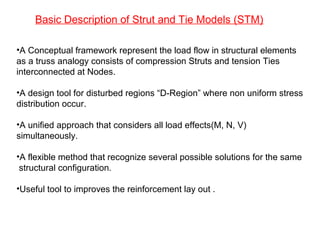
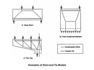
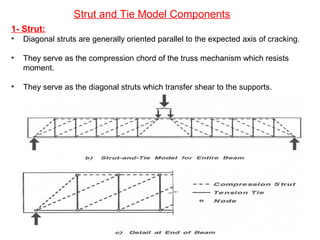
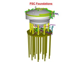
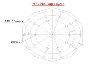
Strut and Tie Model
Pile Cap
Primary Separation Cell (PSC) Foundations
By
Islam Mohamed
October 2011
Calgary, AB
Canada
Presented To
Amec America Ltd
CSA Department
•A Conceptual framework represent the load flow in structural elements
as a truss analogy consists of compression Struts and tension Ties
interconnected at Nodes.
•A design tool for disturbed regions “D-Region” where non uniform stress
distribution occur.
•A unified approach that considers all load effects(M, N, V)
simultaneously.
•A flexible method that recognize several possible solutions for the same
structural configuration.
•Useful tool to improves the reinforcement lay out .
Basic Description of Strut and Tie Models (STM)
Examples of Strut-and-Tie Models
Strut and Tie Model Components
1- Strut:
• Diagonal struts are generally oriented parallel to the expected axis of cracking.
• They serve as the compression chord of the truss mechanism which resists
moment.
• They serve as the diagonal struts which transfer shear to the supports.
-There are three types of struts:
•The simplest type is the “prism” which has a constant width.
•The second form is the “bottle” in which the strut expands or contracts along its
length.
•The final type is the “fan” where an array of struts with varying inclination meet at
or radiate from a single node.
2- Ties:
• Tensions ties include stirrups, longitudinal(tension chord) reinforcement,
and any special detail reinforcement.
• A critical consideration in the detailing of the STM is the provision of
adequate anchorage for the reinforcement.
3- Nodes:
• Nodes are analogous to joints in a truss where forces are transferred
between struts and ties.
• Nodes are subject to a multidirectional state of stress.
• Nodes are classified by the types of forces being connected.
Basic Type of Nodes: (a) CCC (b) CCT (c) CTT (d) TTT
(Schlaich et al. 1987)
B-Regions and D-Regions
• Based on St. Venant's principle, a D-Region assumed to extent about one
section depth from the load or discontinuity.
• Hence, for a deep beam the D-region has a depth of h and length up to 2h one way
or two way from the disturbance, this establishes the smallest angle between a strut
and tie attached to one node as arctan (h/2h) = 26.5o
.
•Two dimensional strut and tie models are used to represent planar structures such
as deep beams and corbels. Three dimensional strut and tie models are used for
structures such as pile caps for two or more rows of piles.
Prerequisites in STM
• Equilibrium must be maintained.
• Ties yield before struts crush (for ductility).
• Tension in concrete is neglected.
• Forces in struts and ties are uni-axial.
• External forces apply at nodes.
• Prestressing is treated as a load.
• Detailing for adequate anchorage.
• Developing STM is an iterative graphical procedure.
STM Formulation procedure
• Specify the Geometrical configuration.
• Indicate load paths from loading Points to supporting points.
• Draw a truss member along load paths.
• Calculate reactions and member forces.
• Repeat the previous 2 procedures until approaching the least tie force.
• Check stresses in truss members.
PSC Foundations
PSC Pile Cap Layout
PSC 10 Columns
20 Piles
•Finite Element Analysis model for PSC Pile Cap to help in figuring out the load path.
•Deflection shape for the pile cap FEA model showing positive bending under PSC
columns within loading span and negative bending outside loading span.
Strut
Tie
•This truss leads to very high tie tension force (T1) relative to results from
FEA model because it ignores the pile cap continuity.
T1
STM First Approach
Column Load
Pile Reaction Pile Reaction
Pile Cap
Effective
Depth
Strut
Tie
• Tie tension forces (T1) in this truss is about 90% of previous one, the difference
in tension is attracted by member T2 .
T1 T1
T2
STM Second Approach
Pile Reaction Pile Reaction Pile ReactionPile Reaction
Column LoadColumn Load
Pile Cap
Effective
Depth
STM Final Truss Model
Struts
Ties
• By repeating the truss in the second approach at all column-pile locations, we get
the above 3D Strut and Tie Model .
3D-Staad Model for final truss approach
Upper Cord and Diagonal Members.
Lower Cord
•Additional ties added between piles to represent the pile cap continuity.
•Tension force in (T1) is about 50% of the first truss approach.
•3m-wide lower reinforcement developed based on tension force in (T1).
•Regular mesh spread along the 7.5m width loading strip based on tension force in the other ties.
•Nominal reinforcement is provided outside loading strip for serviceability consideration.
Reinforcement Layout Considering the STM Results
Conclusion
• For deep structures such as pile caps STM more closely addresses reality.
• STM allows flexibility in arriving at solutions.
• Typically STM results in higher flexure reinforcement, but you don’t have to
check shear.
• Understanding the STM helps distribute reinforcement appropriately.
• The most representative STM results in the least reinforcement.

Strut and Tie Model for Pile Cap

  • 1.
    Strut and TieModel Pile Cap Primary Separation Cell (PSC) Foundations By Islam Mohamed October 2011 Calgary, AB Canada Presented To Amec America Ltd CSA Department
  • 2.
    •A Conceptual frameworkrepresent the load flow in structural elements as a truss analogy consists of compression Struts and tension Ties interconnected at Nodes. •A design tool for disturbed regions “D-Region” where non uniform stress distribution occur. •A unified approach that considers all load effects(M, N, V) simultaneously. •A flexible method that recognize several possible solutions for the same structural configuration. •Useful tool to improves the reinforcement lay out . Basic Description of Strut and Tie Models (STM)
  • 3.
  • 4.
    Strut and TieModel Components 1- Strut: • Diagonal struts are generally oriented parallel to the expected axis of cracking. • They serve as the compression chord of the truss mechanism which resists moment. • They serve as the diagonal struts which transfer shear to the supports.
  • 5.
    -There are threetypes of struts: •The simplest type is the “prism” which has a constant width. •The second form is the “bottle” in which the strut expands or contracts along its length. •The final type is the “fan” where an array of struts with varying inclination meet at or radiate from a single node.
  • 6.
    2- Ties: • Tensionsties include stirrups, longitudinal(tension chord) reinforcement, and any special detail reinforcement. • A critical consideration in the detailing of the STM is the provision of adequate anchorage for the reinforcement. 3- Nodes: • Nodes are analogous to joints in a truss where forces are transferred between struts and ties. • Nodes are subject to a multidirectional state of stress. • Nodes are classified by the types of forces being connected. Basic Type of Nodes: (a) CCC (b) CCT (c) CTT (d) TTT (Schlaich et al. 1987)
  • 7.
  • 8.
    • Based onSt. Venant's principle, a D-Region assumed to extent about one section depth from the load or discontinuity. • Hence, for a deep beam the D-region has a depth of h and length up to 2h one way or two way from the disturbance, this establishes the smallest angle between a strut and tie attached to one node as arctan (h/2h) = 26.5o . •Two dimensional strut and tie models are used to represent planar structures such as deep beams and corbels. Three dimensional strut and tie models are used for structures such as pile caps for two or more rows of piles.
  • 9.
    Prerequisites in STM •Equilibrium must be maintained. • Ties yield before struts crush (for ductility). • Tension in concrete is neglected. • Forces in struts and ties are uni-axial. • External forces apply at nodes. • Prestressing is treated as a load. • Detailing for adequate anchorage. • Developing STM is an iterative graphical procedure.
  • 10.
    STM Formulation procedure •Specify the Geometrical configuration. • Indicate load paths from loading Points to supporting points. • Draw a truss member along load paths. • Calculate reactions and member forces. • Repeat the previous 2 procedures until approaching the least tie force. • Check stresses in truss members.
  • 11.
  • 12.
    PSC Pile CapLayout PSC 10 Columns 20 Piles
  • 13.
    •Finite Element Analysismodel for PSC Pile Cap to help in figuring out the load path. •Deflection shape for the pile cap FEA model showing positive bending under PSC columns within loading span and negative bending outside loading span.
  • 14.
    Strut Tie •This truss leadsto very high tie tension force (T1) relative to results from FEA model because it ignores the pile cap continuity. T1 STM First Approach Column Load Pile Reaction Pile Reaction Pile Cap Effective Depth
  • 15.
    Strut Tie • Tie tensionforces (T1) in this truss is about 90% of previous one, the difference in tension is attracted by member T2 . T1 T1 T2 STM Second Approach Pile Reaction Pile Reaction Pile ReactionPile Reaction Column LoadColumn Load Pile Cap Effective Depth
  • 16.
    STM Final TrussModel Struts Ties • By repeating the truss in the second approach at all column-pile locations, we get the above 3D Strut and Tie Model .
  • 17.
    3D-Staad Model forfinal truss approach
  • 18.
    Upper Cord andDiagonal Members.
  • 19.
    Lower Cord •Additional tiesadded between piles to represent the pile cap continuity. •Tension force in (T1) is about 50% of the first truss approach.
  • 20.
    •3m-wide lower reinforcementdeveloped based on tension force in (T1). •Regular mesh spread along the 7.5m width loading strip based on tension force in the other ties. •Nominal reinforcement is provided outside loading strip for serviceability consideration. Reinforcement Layout Considering the STM Results
  • 21.
    Conclusion • For deepstructures such as pile caps STM more closely addresses reality. • STM allows flexibility in arriving at solutions. • Typically STM results in higher flexure reinforcement, but you don’t have to check shear. • Understanding the STM helps distribute reinforcement appropriately. • The most representative STM results in the least reinforcement.