
Recommended
More Related Content
Similar to VHDL_Lec1.pptx
Similar to VHDL_Lec1.pptx (20)
Recently uploaded
Recently uploaded (20)
VHDL_Lec1.pptx
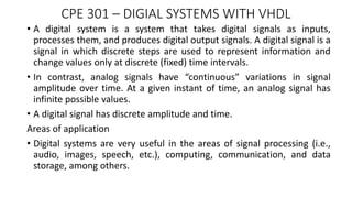
- 1. CPE 301 – DIGIAL SYSTEMS WITH VHDL • A digital system is a system that takes digital signals as inputs, processes them, and produces digital output signals. A digital signal is a signal in which discrete steps are used to represent information and change values only at discrete (fixed) time intervals. • In contrast, analog signals have “continuous” variations in signal amplitude over time. At a given instant of time, an analog signal has infinite possible values. • A digital signal has discrete amplitude and time. Areas of application • Digital systems are very useful in the areas of signal processing (i.e., audio, images, speech, etc.), computing, communication, and data storage, among others.
- 2. Brief History of Digital System • In 1939, Harvard University built the Harvard Mark I, which went into operation in 1943. was used to compute ballistic tables for the U.S. Navy. • 1945 - ENIAC (Electronic Numerical Integrator and Computer) built component by component at the Moore School of Electrical Engineering at the University of Pennsylvania. • 1951 – UNIVAC, first commercially produced computer • These first-generation computers used vacuum tubes and valves as primary electronic components were bulky, expensive, and consumed immense amounts of power
- 3. Brief History of Digital System • 1948 – Transistor invented at the Bell Telephone Laboratories by physicists John Bardeen, Walter Brattain, and William Shockley. • Transistor revolutionized the way that computers were built. • Then with the arrival of IC technology, their utility increased exponentially. • ICs are inexpensive when produced in large numbers, reliable, and consume much less power than do vacuum tubes. • IC technology makes it possible to build complete digital building blocks into single, minute silicon “chips.”
- 4. STANDARD LOGIC DEVICES • Many ICs are available as standard chips. standard chips because their functionality and configuration meet agreed-upon standards • The advantages of using standard chips are their ease of use and ready availability. • Generally do not have complex functionality means that many such chips have to be put together on a PCB leading to a requirement for more area and components. • Examples include: 7400 series, such as the 7404 (hex inverters) and 7432 (quad two-input OR gates).
- 5. CUSTOM-DESIGNED LOGIC DEVICES • Designed to meet the specific requirements of an application i.e. ASIC • They are optimized for a specific application hence perform better than equivalent circuits built from off-the-shelf ICs or programmable logic devices. • They occupy very little area (i.e. less PCB area), as all of the logic can be built into one chip. Disadvantages • They are economical only when there is bulk production of the ICs • It requires the work of highly skilled engineers in the design, manufacturing, and test stages. • Design time for the chips very high (lot of verification to check for correct functionality)
- 6. PROGRAMMABLE LOGIC DEVICES • PLDs have a very general structure and contain programmable switches, which allow the user to configure the internal circuitry to perform the desired function. • The programmer can configure these switches by writing a program in a hardware description language (HDL) such as VHDL or Verilog and “downloading” it into the chip. • Popular types of PLDs include: Simple programmable logic devices (SPLDs) Programmable array logic (PAL) Programmable logic array (PLA) Generic array logic (GAL) Complex programmable logic devices (CPLDs) FPGA (field-programmable gate arrays) FPIC (field-programmable interconnect)
- 7. • Schematic Structure of PALs and PLAs CPLD Internal Structure FPGA Internal Structure
- 8. • Different manufacturers of PLDs choose different architectures for implementing the logic blocks and the programmable interconnection switch matrices. • FPGAs have the highest gate count among the various PLDs, which can accommodate much larger designs than can SPLDs and CPLDs. • FPGAs have millions of transistors in one chip. • PALs and PLAs generally carry just a few hundred or a few thousand gates. • PLD manufacturers include: Altera Corporation Xilinx Inc. LatticeSemiconductor Cypress Semiconductor Atmel, Actel, Lucent Technologies, and QuickLogic.
- 9. Bases and Number Systems • A number in decimal representation is made of digits that range from 0 to 9. Consider the following decimal number: (4261)10 = 4 x 104 x 2 x 102 + 6 x 101 + 1 x 100 • This number is normally written as 4261 • Decimal representations are said to be base-10 or radix-10 numbers because each digit has 10 possible values, weighted as a power of 10, depending on the position of the digit in the number. • Similarly, in binary representation, each binary digit has two possible values, 1 and 0, and the digits are weighted as a power of 2, depending on their position in the number. The binary system of representation is also known as a base-2 system. (1001)2 = 1 x 23 + 0 x 22+0 x 21+ 1 x 20 = (9)10
- 10. • Numbers in binary form can be rather long, exhausting, and difficult to remember. Binary numbers are often represented in more compact forms using the octal (base 8) and hexadecimal (base 16) systems. Octal system: digits 0 through 7 Hexadecimal system: 0-9 and the letters A-F, where A represents the decimal 10 and F represents the decimal 15.
- 15. Binary-to-Octal and Hexadecimal Conversions
- 16. Octal and hexadecimal to binary conversions
- 17. DATA ORGANIZATION • A binary number is a sequence of bits that may represent an actual binary number, a character, or an instruction. • A group of consecutive 4 bits is called a nibble. • A nibble is used to represent a BCD or hexadecimal digit. • A group of consecutive 8 bits is called a byte, which is the smallest addressable data in memory. • A byte is also used to represent an alphanumeric character. • A group of consecutive 16 bits, called a word, can be divided into a high byte and a low byte.
- 18. Exercise1 • Convert the following decimal numbers into binary, octal, and hexadecimal numbers. (a) 127 (b) 159 (c) 789 (d) 1987 (e) 509.43 (f) 2961.72 (g) 4325.53 (h) 351.827 (i) 612.075
- 19. Exercise2 • Convert the following hexadecimal numbers into binary, octal, and decimal numbers. (a) 32E.15 (b) 1010.AA (c) C0DE.02 (d) 11F8.99 (e) CAFE.45 (f) F0AE.4A (g) EEFF.99 (h) 10EF.75 (i) BABE.01 (j) 2004.FEB
Editor's Notes
- Digital systems are so commonplace in today’s world that we tend to miss seeing them. Almost all electronic systems are partially or totally digitally based. Of course, real-world signals are all analog, and interfacing to the outside world requires conversion of a signal (information) from digital to analog.
- A ballistic table or ballistic chart is a tool which predicts the trajectory of a projectile, and is used to compensate for physical effects in order to increase the probability of the projectile reaching the intended target. Ballistic tables are used in hunting, sport shooting, military and scientific applications.
- Transistors are used as electrical switches that can be in the “on” or “off” state and so can be used to build digital circuits and systems.
- These are referred to as standard chips because their functionality and configuration meet agreed-upon standards.
- Chips designed to meet the specific requirements of an application are known as application-specific integrated circuits (ASICs) or custom-designed chips.
- Advances in VLSI technology made possible the design of special chips, which can be configured by a user to implement different logic circuits. Early SPLDs were simple and consisted of an array of AND gates driving an array of OR gates. An AND gate (known as an AND plane or AND array) feeds a set of OR gates (an OR plane). This helps in realizing a function in the sum-of-products form. The difference btw PALs & PLAs is that in PLA, both the AND & OR planes are programmable, whereas in PALs, the AND plane is programmable but the OR plane is fixed. PALs & PLAs are useful for small digital circuits which do not require more than 32 inputs and outputs. CPLDs are used to implement circuits with more inputs and outputs.
- FPGAs differ from the other PLDs and generally offer the highest logic capacity. An FPGA consists of an array of complex logic blocks (CLBs) surrounded by programmable I/O blocks (IOBs) and connected by a programmable interconnection network.
- Binary systems is a fundamental feature of modern digital electronic devices.
- A conversion is carried out by first dividing the given decimal number by 2. The quotient that results from each division step is again divided by 2 and the remainders are noted in each step. The remainders form the actual binary number.
- The conversion of a binary number to an octal number or a hexadecimal number requires converting the binary digits in groups of 3 or 4, respectively, starting from the least significant bit.
- Once the binary number is formed, it can be converted into any of the other representation systems using the procedures above.
- In general, the size of the microcomputer internal registers determines the size of binary grouping. A 16-bit microcomputer has two bytes, or a 16-bit word size. However, the memory unit is divided into an 8-bit, or byte, word length. For example, to store a 16-bit number, the microcomputer uses two consecutive byte locations in the memory space.