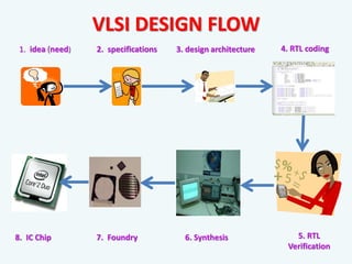
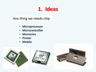
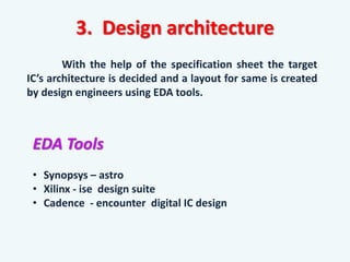
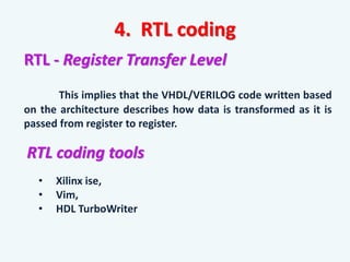
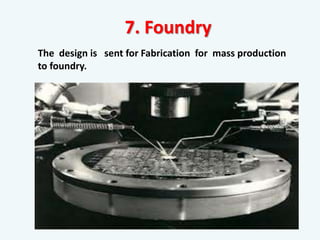
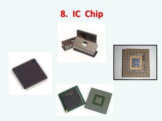
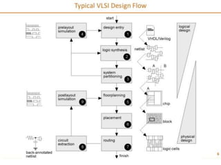
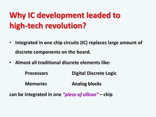
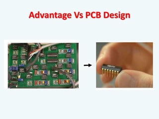
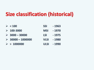
Lecture
Integrated Circuits
Why IC development leaded to
high-tech revolution?
• Integrated in one chip circuits (IC) replaces large amount of
discrete components on the board.
• Almost all traditional discrete elements like:
Processors Digital Discrete Logic
Memories Analog blocks
can be integrated in one "piece of silicon" – chip
Advantage Vs PCB Design
Size classification (historical)
 < 100 SSI - 1963
 100-3000 MSI - 1970
 3000 – 30000 LSI - 1975
 30000 – 1000000 VLSI - 1980
 > 1000000 ULSI - 1990
Introduction to VLSI circuit Industry
Introduction:
Very-large-scale integration (VLSI) is the process of
creating an integrated circuit by combining thousands of
transistors into a single chip (few mm2  few cm2).
Objectives:
Design “efficient” VLSI systems that has:
 Circuit Speed (high)
 Power consumption (low)
 Design Area (low)
Fundamental Law of VLSI
Technology
• Gordon Moore: co-founder of Intel
• Observation that, over the history of computing hardware,
the number of transistors in a dense integrated circuit
doubles approximately every 18 months.
• Today’s chips have close to 500 Million transistors
VLSI
FRONT END BACK END
Designing
& Testing Part
Development
& Fabrication Part
What is an ASIC?
• ASIC (Application Specific Integrated Circuit)
 Fixed Function chip
What is an FPGA?
• FPGA (Field Programmable Gate Array)
 Programmable chip
Processor Vs. FPGA
Processor:
Hardware functionality already
exists, software ‘programs’ use
of hardware
FPGA:
Hardware functionality
created by ‘programming’
PROGRAM GATES
PROGRAM INSTRUCTIONS
MEM
A B
ALU
HW FIXED HW CREATED
FPGA Vs. ASIC
Category FPGA ASIC
Design time / Time to Market + -
Design Cost + -
Performance [Speed, Power, Density] - +
Size [Area] - +
Total Cost + +
Changes to design + -
VLSI DESIGN FLOW
1. idea (need) 2. specifications 3. design architecture 4. RTL coding
5. RTL
Verification
6. Synthesis
7. Foundry
8. IC Chip
1. Ideas
• Microprocessor
• Microcontroller
• Memories
• Printer
• Mobile
Any thing we needs chip
Here, vendors may want to get feedback from potential
customers on what they are looking for
• Instruction set
• Interface (I/O pins)
• Organization of the system
• Functionality of each unit in the system, and how to
communicate it to other units.
2. Specifications
3. Design architecture
With the help of the specification sheet the target
IC’s architecture is decided and a layout for same is created
by design engineers using EDA tools.
EDA Tools
• Synopsys – astro
• Xilinx - ise design suite
• Cadence - encounter digital IC design
4. RTL coding
RTL - Register Transfer Level
This implies that the VHDL/VERILOG code written based
on the architecture describes how data is transformed as it is
passed from register to register.
RTL coding tools
• Xilinx ise,
• Vim,
• HDL TurboWriter
VHDL
• Not case sensitive.
• Difficult to learn.
• Based on pascal & ada.
• Strongly typed.
• Case sensitive.
• Easy to learn.
• Based on c.
• Not strongly typed.
HDL – Hardware Description Language
A programming language that can describe the functionality
and timing of the hardware.
Types of HDL
• VHDL
• VERILOG
• SYSTEM VERILOG
VERILOG
Difference
5. RTL Verification
This ensures that the design is logically correct and
without major timing errors.
RTL verification tools
• Modelsim
• Verilog - XL
• Xilinx ise
RTL verification wave form
6. Synthesis
Logic synthesis is a process by which the desired circuit is
turned into a design in terms of logic gates which drives the
circuit or architecture.
Synthesis tools:
• FPGA - Altera, Digiland, Xilinx
• CPLD - Altera , Digiland
7. Foundry
The design is sent for Fabrication for mass production
to foundry.
8. IC Chip
FPGA KIT
XC3S400PQ208
Application of VLSI
VLSI companies in india
 VLSI is suitabale for fabrication of larger number of
components on a single chip.
 VHDL / Verilog is used for digital circuit designing and
to validate the design and check the design specification.
CONCLUSION
THANK YOU

Integrated Circuits introduction and fpga

  • 1.
  • 2.
    Why IC developmentleaded to high-tech revolution? • Integrated in one chip circuits (IC) replaces large amount of discrete components on the board. • Almost all traditional discrete elements like: Processors Digital Discrete Logic Memories Analog blocks can be integrated in one "piece of silicon" – chip
  • 3.
  • 4.
    Size classification (historical) < 100 SSI - 1963  100-3000 MSI - 1970  3000 – 30000 LSI - 1975  30000 – 1000000 VLSI - 1980  > 1000000 ULSI - 1990
  • 5.
    Introduction to VLSIcircuit Industry Introduction: Very-large-scale integration (VLSI) is the process of creating an integrated circuit by combining thousands of transistors into a single chip (few mm2  few cm2). Objectives: Design “efficient” VLSI systems that has:  Circuit Speed (high)  Power consumption (low)  Design Area (low)
  • 6.
    Fundamental Law ofVLSI Technology • Gordon Moore: co-founder of Intel • Observation that, over the history of computing hardware, the number of transistors in a dense integrated circuit doubles approximately every 18 months. • Today’s chips have close to 500 Million transistors
  • 7.
    VLSI FRONT END BACKEND Designing & Testing Part Development & Fabrication Part
  • 8.
    What is anASIC? • ASIC (Application Specific Integrated Circuit)  Fixed Function chip What is an FPGA? • FPGA (Field Programmable Gate Array)  Programmable chip
  • 9.
    Processor Vs. FPGA Processor: Hardwarefunctionality already exists, software ‘programs’ use of hardware FPGA: Hardware functionality created by ‘programming’ PROGRAM GATES PROGRAM INSTRUCTIONS MEM A B ALU HW FIXED HW CREATED
  • 10.
    FPGA Vs. ASIC CategoryFPGA ASIC Design time / Time to Market + - Design Cost + - Performance [Speed, Power, Density] - + Size [Area] - + Total Cost + + Changes to design + -
  • 11.
    VLSI DESIGN FLOW 1.idea (need) 2. specifications 3. design architecture 4. RTL coding 5. RTL Verification 6. Synthesis 7. Foundry 8. IC Chip
  • 12.
    1. Ideas • Microprocessor •Microcontroller • Memories • Printer • Mobile Any thing we needs chip
  • 13.
    Here, vendors maywant to get feedback from potential customers on what they are looking for • Instruction set • Interface (I/O pins) • Organization of the system • Functionality of each unit in the system, and how to communicate it to other units. 2. Specifications
  • 14.
    3. Design architecture Withthe help of the specification sheet the target IC’s architecture is decided and a layout for same is created by design engineers using EDA tools. EDA Tools • Synopsys – astro • Xilinx - ise design suite • Cadence - encounter digital IC design
  • 16.
    4. RTL coding RTL- Register Transfer Level This implies that the VHDL/VERILOG code written based on the architecture describes how data is transformed as it is passed from register to register. RTL coding tools • Xilinx ise, • Vim, • HDL TurboWriter
  • 17.
    VHDL • Not casesensitive. • Difficult to learn. • Based on pascal & ada. • Strongly typed. • Case sensitive. • Easy to learn. • Based on c. • Not strongly typed. HDL – Hardware Description Language A programming language that can describe the functionality and timing of the hardware. Types of HDL • VHDL • VERILOG • SYSTEM VERILOG VERILOG Difference
  • 18.
    5. RTL Verification Thisensures that the design is logically correct and without major timing errors. RTL verification tools • Modelsim • Verilog - XL • Xilinx ise
  • 19.
  • 20.
    6. Synthesis Logic synthesisis a process by which the desired circuit is turned into a design in terms of logic gates which drives the circuit or architecture. Synthesis tools: • FPGA - Altera, Digiland, Xilinx • CPLD - Altera , Digiland
  • 21.
    7. Foundry The designis sent for Fabrication for mass production to foundry.
  • 22.
  • 24.
  • 25.
  • 26.
  • 27.
     VLSI issuitabale for fabrication of larger number of components on a single chip.  VHDL / Verilog is used for digital circuit designing and to validate the design and check the design specification. CONCLUSION
  • 28.

Editor's Notes