SlideShare a Scribd company logo
1 of 5
Distance measuring equipment
D-VOR/DME ground station
DME antenna beside the DME transponder shelter
Distance measuring equipment (DME) is a transponder-based radio navigation technology that
measures slant range distance by timing the propagation delay of VHF or UHF radio signals.
Developed in Australia, it was invented by James "Gerry" Gerrand[1]
under the supervision of Edward
George "Taffy" Bowen while employed as Chief of the Division of Radiophysics of
the Commonwealth Scientific and Industrial Research Organisation (CSIRO). Another engineered
version of the system was deployed by Amalgamated Wireless Australasia Limited in the early
1950s operating in the 200 MHz VHF band. This Australian domestic version was referred to by the
Federal Department of Civil Aviation as DME(D) (or DME Domestic), and the later international
version adopted by ICAO as DME(I).
DME is similar to secondary radar, except in reverse. The system was a post-war development of
the IFF (identification friend or foe) systems of World War II. To maintain compatibility, DME is
functionally identical to the distance measuring component of TACAN.
Operation
Aircraft use DME to determine their distance from a land-based transponder by sending and
receiving pulse pairs – two pulses of fixed duration and separation. The ground stations are typically
collocated with VORs or ILS systems. A low-power DME can be collocated with an ILS glide slope
antenna installation where it provides an accurate distance to touchdown function, similar to that
otherwise provided by ILS marker beacons.
A typical Distance measuring equipment ground transponder system for en-route or terminal
navigation will have a 1 kW peak pulse output on the assigned UHF channel.
Hardware
The DME system comprises a UHF transmitter/receiver (interrogator) in the aircraft and a UHF
receiver/transmitter (transponder) on the ground.
DME distance and VOR/ADF cockpit display instruments
Timing
SEARCH MODE: 150 interrogation pulse-pairs per second.
The aircraft interrogates the ground transponder with a series of pulse-pairs (interrogations) and,
after a precise time delay (typically 50 microseconds), the ground station replies with an identical
sequence of pulse-pairs. The DME receiver in the aircraft searches for reply pulse-pairs (X-mode=
12 microsecond spacing) with the correct interval and reply pattern to its original interrogation
pattern. (Pulse-pairs that are not coincident with the individual aircraft's interrogation pattern e.g. not
synchronous, are referred to as filler pulse-pairs, or squitter. Also, replies to other aircraft that are
therefore non-synchronous also appear as squitter).
TRACK MODE: less than 30 interrogation Pulse-pairs per second, as the average number of pulses
in SEARCH and TRACK is limited to max 30 pulse pairs per second.
The aircraft interrogator locks on to the DME ground station once it recognizes a particular reply
pulse sequence has the same spacing as the original interrogation sequence. Once the receiver is
locked on, it has a narrower window in which to look for the echoes and can retain lock.
Distance calculation
A radio signal takes approximately 12.36 microseconds to travel 1 nautical mile (1,852 m) to the
target and back—also referred to as a radar-mile. The time difference between interrogation and
reply, minus the 50 microsecond ground transponder delay, is measured by the interrogator's timing
circuitry and converted to a distance measurement (slant range), in nautical miles, then displayed on
the cockpit DME display.
The distance formula, distance = rate * time, is used by the DME receiver to calculate its distance
from the DME ground station. The rate in the calculation is the velocity of the radio pulse, which is
the speed of light (roughly 300,000,000 m/s or 186,000 mi/s). The time in the calculation is (total
time – 50µs)/2.
Accuracy
The accuracy of DME ground stations is 185 m (±0.1 nmi).[2]
It's important to understand that DME
provides the physical distance from the aircraft to the DME transponder. This distance is often
referred to as 'slant range' and depends trigonometrically upon both the altitude above the
transponder and the ground distance from it.
For example, an aircraft directly above the DME station at 6,076 ft (1 nmi) altitude would still show
1.0 nmi (1.9 km) on the DME readout. The aircraft is technically a mile away, just a mile straight up.
Slant range error is most pronounced at high altitudes when close to the DME station.
Radio-navigation aids must keep a certain degree of accuracy, given by international standards,
FAA,[3]
EASA, ICAO, etc. To assure this is the case, flight inspection organizations check periodically
critical parameters with properly equipped aircraft to calibrate and certify DME precision.
ICAO recommends accuracy of less than the sum of 0.25 nmi plus 1.25% of the distance measured.
Specification
A typical DME transponder can provide distance information to 100 to 200 aircraft at a time. Above
this limit the transponder avoids overload by limiting the sensitivity of the receiver. Replies to weaker
more distant interrogations are ignored to lower the transponder load.
Radio frequency and modulation data
DME frequencies are paired to VHF omnidirectional range (VOR) frequencies and a DME
interrogator is designed to automatically tune to the corresponding DME frequency when the
associated VOR frequency is selected. An airplane’s DME interrogator uses frequencies from 1025
to 1150 MHz. DME transponders transmit on a channel in the 962 to 1213 MHz range and receive
on a corresponding channel between 1025 and 1150 MHz. The band is divided into 126 channels for
interrogation and 126 channels for reply. The interrogation and reply frequencies always differ by
63 MHz. The spacing of all channels is 1 MHz with a signal spectrum width of 100 kHz.
Technical references to X and Y channels relate only to the spacing of the individual pulses in the
DME pulse pair, 12 microsecond spacing for X channels and 30 microsecond spacing for Y
channels.
DME facilities identify themselves with a 1,350 Hz Morse code three letter identity. If collocated with
a VOR or ILS, it will have the same identity code as the parent facility. Additionally, the DME will
identify itself between those of the parent facility. The DME identity is 1,350 Hz to differentiate itself
from the 1,020 Hz tone of the VOR or the ILS localizer.
Terminal DME
A terminal DME, referred to as a TDME in navigational charts, is a DME that is designed to provide a
0 reading at the threshold point of the runway, regardless of the physical location of the equipment. It
is typically associated with ILS or other instrument approach.
Future
DME operation will continue and possibly expand as an alternate navigation source to space-based
navigational systems such as

More Related Content

Similar to DME Ground Station Guide

Similar to DME Ground Station Guide (20)

Distance Measurement equipment (DME)
Distance Measurement equipment (DME)Distance Measurement equipment (DME)
Distance Measurement equipment (DME)
 
AAI Bhopal, Training Presentation (CNS)
AAI Bhopal, Training Presentation (CNS)AAI Bhopal, Training Presentation (CNS)
AAI Bhopal, Training Presentation (CNS)
 
trainingpresentation-180628160709.pptx
trainingpresentation-180628160709.pptxtrainingpresentation-180628160709.pptx
trainingpresentation-180628160709.pptx
 
Airports authority of india (aai) training report
Airports authority of india (aai) training reportAirports authority of india (aai) training report
Airports authority of india (aai) training report
 
Presentation on CNS (AAI)
Presentation on CNS (AAI)Presentation on CNS (AAI)
Presentation on CNS (AAI)
 
Aai industrial training
Aai industrial trainingAai industrial training
Aai industrial training
 
PPt on AAI
PPt on AAIPPt on AAI
PPt on AAI
 
PPt Presentation on CNS (AAI)
PPt Presentation on CNS (AAI)PPt Presentation on CNS (AAI)
PPt Presentation on CNS (AAI)
 
Airport Authority of India
Airport Authority of IndiaAirport Authority of India
Airport Authority of India
 
RADAR
RADAR RADAR
RADAR
 
318099023-Internship-at-AAI-Baroda.pdf
318099023-Internship-at-AAI-Baroda.pdf318099023-Internship-at-AAI-Baroda.pdf
318099023-Internship-at-AAI-Baroda.pdf
 
aircraft navigation equipment
aircraft navigation equipmentaircraft navigation equipment
aircraft navigation equipment
 
Doppler VHF Omni Directional Range (DVOR)
Doppler VHF Omni Directional Range (DVOR)Doppler VHF Omni Directional Range (DVOR)
Doppler VHF Omni Directional Range (DVOR)
 
Communication navigation & Surveillance Report
Communication navigation & Surveillance ReportCommunication navigation & Surveillance Report
Communication navigation & Surveillance Report
 
Lesson ssr
Lesson ssrLesson ssr
Lesson ssr
 
Navigation aids
Navigation aidsNavigation aids
Navigation aids
 
Radar
RadarRadar
Radar
 
Air craft surveillance
Air craft surveillanceAir craft surveillance
Air craft surveillance
 
Air Traffic Control
Air Traffic ControlAir Traffic Control
Air Traffic Control
 
Aircraft navigation system
Aircraft navigation systemAircraft navigation system
Aircraft navigation system
 

More from CyprianObota

AREA NAVVIGATION.pptx
AREA NAVVIGATION.pptxAREA NAVVIGATION.pptx
AREA NAVVIGATION.pptxCyprianObota
 
Principles of Communication Systems 2.docx
Principles of Communication Systems 2.docxPrinciples of Communication Systems 2.docx
Principles of Communication Systems 2.docxCyprianObota
 
Elementary algebra notes 001.pdf
Elementary algebra notes 001.pdfElementary algebra notes 001.pdf
Elementary algebra notes 001.pdfCyprianObota
 
UNDERWATER LACATOR BEACON.pptx
UNDERWATER LACATOR BEACON.pptxUNDERWATER LACATOR BEACON.pptx
UNDERWATER LACATOR BEACON.pptxCyprianObota
 
Simultaneous equations teaching.pdf
Simultaneous equations teaching.pdfSimultaneous equations teaching.pdf
Simultaneous equations teaching.pdfCyprianObota
 
TRAFFIC COLLISION AVOIDANCE SYSTEM NOTES 2.docx
TRAFFIC COLLISION AVOIDANCE SYSTEM NOTES 2.docxTRAFFIC COLLISION AVOIDANCE SYSTEM NOTES 2.docx
TRAFFIC COLLISION AVOIDANCE SYSTEM NOTES 2.docxCyprianObota
 
Tuned radio frequency TRF receiver.docx
Tuned radio frequency TRF receiver.docxTuned radio frequency TRF receiver.docx
Tuned radio frequency TRF receiver.docxCyprianObota
 
INERTIAL NAVVIGATION SYSTEM.pptx
INERTIAL NAVVIGATION SYSTEM.pptxINERTIAL NAVVIGATION SYSTEM.pptx
INERTIAL NAVVIGATION SYSTEM.pptxCyprianObota
 
The Global Positioning System notes.docx
The Global Positioning System notes.docxThe Global Positioning System notes.docx
The Global Positioning System notes.docxCyprianObota
 
RADIO RECEIVER STAGES.pptx
RADIO RECEIVER STAGES.pptxRADIO RECEIVER STAGES.pptx
RADIO RECEIVER STAGES.pptxCyprianObota
 
TRAFFIC COLLISION AVOIDANCE SYSTEM(TCAS).pptx
TRAFFIC COLLISION AVOIDANCE SYSTEM(TCAS).pptxTRAFFIC COLLISION AVOIDANCE SYSTEM(TCAS).pptx
TRAFFIC COLLISION AVOIDANCE SYSTEM(TCAS).pptxCyprianObota
 
Radio REceiver RF,mixer and Detector.docx
Radio REceiver RF,mixer and Detector.docxRadio REceiver RF,mixer and Detector.docx
Radio REceiver RF,mixer and Detector.docxCyprianObota
 
MAINTENANCE OF COMMS SYSTEMS.pptx
MAINTENANCE OF  COMMS SYSTEMS.pptxMAINTENANCE OF  COMMS SYSTEMS.pptx
MAINTENANCE OF COMMS SYSTEMS.pptxCyprianObota
 
RADIO RECEIVERS.pptx
RADIO RECEIVERS.pptxRADIO RECEIVERS.pptx
RADIO RECEIVERS.pptxCyprianObota
 
RADIO TRANSMITTERS.docx
RADIO TRANSMITTERS.docxRADIO TRANSMITTERS.docx
RADIO TRANSMITTERS.docxCyprianObota
 
INTRODUCTION TO RADIO COMMUNICATION SYSTEMS 1.docx
INTRODUCTION TO RADIO COMMUNICATION SYSTEMS 1.docxINTRODUCTION TO RADIO COMMUNICATION SYSTEMS 1.docx
INTRODUCTION TO RADIO COMMUNICATION SYSTEMS 1.docxCyprianObota
 
Instrument landing system.docx
Instrument landing system.docxInstrument landing system.docx
Instrument landing system.docxCyprianObota
 
Radio receiver ccts images.docx
Radio receiver ccts images.docxRadio receiver ccts images.docx
Radio receiver ccts images.docxCyprianObota
 
Quarter wave vertical antenna.docx
Quarter wave vertical antenna.docxQuarter wave vertical antenna.docx
Quarter wave vertical antenna.docxCyprianObota
 

More from CyprianObota (20)

AREA NAVVIGATION.pptx
AREA NAVVIGATION.pptxAREA NAVVIGATION.pptx
AREA NAVVIGATION.pptx
 
Principles of Communication Systems 2.docx
Principles of Communication Systems 2.docxPrinciples of Communication Systems 2.docx
Principles of Communication Systems 2.docx
 
Elementary algebra notes 001.pdf
Elementary algebra notes 001.pdfElementary algebra notes 001.pdf
Elementary algebra notes 001.pdf
 
UNDERWATER LACATOR BEACON.pptx
UNDERWATER LACATOR BEACON.pptxUNDERWATER LACATOR BEACON.pptx
UNDERWATER LACATOR BEACON.pptx
 
Simultaneous equations teaching.pdf
Simultaneous equations teaching.pdfSimultaneous equations teaching.pdf
Simultaneous equations teaching.pdf
 
TRAFFIC COLLISION AVOIDANCE SYSTEM NOTES 2.docx
TRAFFIC COLLISION AVOIDANCE SYSTEM NOTES 2.docxTRAFFIC COLLISION AVOIDANCE SYSTEM NOTES 2.docx
TRAFFIC COLLISION AVOIDANCE SYSTEM NOTES 2.docx
 
Tuned radio frequency TRF receiver.docx
Tuned radio frequency TRF receiver.docxTuned radio frequency TRF receiver.docx
Tuned radio frequency TRF receiver.docx
 
INERTIAL NAVVIGATION SYSTEM.pptx
INERTIAL NAVVIGATION SYSTEM.pptxINERTIAL NAVVIGATION SYSTEM.pptx
INERTIAL NAVVIGATION SYSTEM.pptx
 
The Global Positioning System notes.docx
The Global Positioning System notes.docxThe Global Positioning System notes.docx
The Global Positioning System notes.docx
 
RADIO RECEIVER STAGES.pptx
RADIO RECEIVER STAGES.pptxRADIO RECEIVER STAGES.pptx
RADIO RECEIVER STAGES.pptx
 
RADIO WAVES.docx
RADIO WAVES.docxRADIO WAVES.docx
RADIO WAVES.docx
 
TRAFFIC COLLISION AVOIDANCE SYSTEM(TCAS).pptx
TRAFFIC COLLISION AVOIDANCE SYSTEM(TCAS).pptxTRAFFIC COLLISION AVOIDANCE SYSTEM(TCAS).pptx
TRAFFIC COLLISION AVOIDANCE SYSTEM(TCAS).pptx
 
Radio REceiver RF,mixer and Detector.docx
Radio REceiver RF,mixer and Detector.docxRadio REceiver RF,mixer and Detector.docx
Radio REceiver RF,mixer and Detector.docx
 
MAINTENANCE OF COMMS SYSTEMS.pptx
MAINTENANCE OF  COMMS SYSTEMS.pptxMAINTENANCE OF  COMMS SYSTEMS.pptx
MAINTENANCE OF COMMS SYSTEMS.pptx
 
RADIO RECEIVERS.pptx
RADIO RECEIVERS.pptxRADIO RECEIVERS.pptx
RADIO RECEIVERS.pptx
 
RADIO TRANSMITTERS.docx
RADIO TRANSMITTERS.docxRADIO TRANSMITTERS.docx
RADIO TRANSMITTERS.docx
 
INTRODUCTION TO RADIO COMMUNICATION SYSTEMS 1.docx
INTRODUCTION TO RADIO COMMUNICATION SYSTEMS 1.docxINTRODUCTION TO RADIO COMMUNICATION SYSTEMS 1.docx
INTRODUCTION TO RADIO COMMUNICATION SYSTEMS 1.docx
 
Instrument landing system.docx
Instrument landing system.docxInstrument landing system.docx
Instrument landing system.docx
 
Radio receiver ccts images.docx
Radio receiver ccts images.docxRadio receiver ccts images.docx
Radio receiver ccts images.docx
 
Quarter wave vertical antenna.docx
Quarter wave vertical antenna.docxQuarter wave vertical antenna.docx
Quarter wave vertical antenna.docx
 

Recently uploaded

Artificial-Intelligence-in-Electronics (K).pptx
Artificial-Intelligence-in-Electronics (K).pptxArtificial-Intelligence-in-Electronics (K).pptx
Artificial-Intelligence-in-Electronics (K).pptxbritheesh05
 
Call Girls Delhi {Jodhpur} 9711199012 high profile service
Call Girls Delhi {Jodhpur} 9711199012 high profile serviceCall Girls Delhi {Jodhpur} 9711199012 high profile service
Call Girls Delhi {Jodhpur} 9711199012 high profile servicerehmti665
 
Software and Systems Engineering Standards: Verification and Validation of Sy...
Software and Systems Engineering Standards: Verification and Validation of Sy...Software and Systems Engineering Standards: Verification and Validation of Sy...
Software and Systems Engineering Standards: Verification and Validation of Sy...VICTOR MAESTRE RAMIREZ
 
ZXCTN 5804 / ZTE PTN / ZTE POTN / ZTE 5804 PTN / ZTE POTN 5804 ( 100/200 GE Z...
ZXCTN 5804 / ZTE PTN / ZTE POTN / ZTE 5804 PTN / ZTE POTN 5804 ( 100/200 GE Z...ZXCTN 5804 / ZTE PTN / ZTE POTN / ZTE 5804 PTN / ZTE POTN 5804 ( 100/200 GE Z...
ZXCTN 5804 / ZTE PTN / ZTE POTN / ZTE 5804 PTN / ZTE POTN 5804 ( 100/200 GE Z...ZTE
 
VIP Call Girls Service Kondapur Hyderabad Call +91-8250192130
VIP Call Girls Service Kondapur Hyderabad Call +91-8250192130VIP Call Girls Service Kondapur Hyderabad Call +91-8250192130
VIP Call Girls Service Kondapur Hyderabad Call +91-8250192130Suhani Kapoor
 
APPLICATIONS-AC/DC DRIVES-OPERATING CHARACTERISTICS
APPLICATIONS-AC/DC DRIVES-OPERATING CHARACTERISTICSAPPLICATIONS-AC/DC DRIVES-OPERATING CHARACTERISTICS
APPLICATIONS-AC/DC DRIVES-OPERATING CHARACTERISTICSKurinjimalarL3
 
Current Transformer Drawing and GTP for MSETCL
Current Transformer Drawing and GTP for MSETCLCurrent Transformer Drawing and GTP for MSETCL
Current Transformer Drawing and GTP for MSETCLDeelipZope
 
HARMONY IN THE HUMAN BEING - Unit-II UHV-2
HARMONY IN THE HUMAN BEING - Unit-II UHV-2HARMONY IN THE HUMAN BEING - Unit-II UHV-2
HARMONY IN THE HUMAN BEING - Unit-II UHV-2RajaP95
 
Call Girls Narol 7397865700 Independent Call Girls
Call Girls Narol 7397865700 Independent Call GirlsCall Girls Narol 7397865700 Independent Call Girls
Call Girls Narol 7397865700 Independent Call Girlsssuser7cb4ff
 
OSVC_Meta-Data based Simulation Automation to overcome Verification Challenge...
OSVC_Meta-Data based Simulation Automation to overcome Verification Challenge...OSVC_Meta-Data based Simulation Automation to overcome Verification Challenge...
OSVC_Meta-Data based Simulation Automation to overcome Verification Challenge...Soham Mondal
 
Model Call Girl in Narela Delhi reach out to us at 🔝8264348440🔝
Model Call Girl in Narela Delhi reach out to us at 🔝8264348440🔝Model Call Girl in Narela Delhi reach out to us at 🔝8264348440🔝
Model Call Girl in Narela Delhi reach out to us at 🔝8264348440🔝soniya singh
 
SPICE PARK APR2024 ( 6,793 SPICE Models )
SPICE PARK APR2024 ( 6,793 SPICE Models )SPICE PARK APR2024 ( 6,793 SPICE Models )
SPICE PARK APR2024 ( 6,793 SPICE Models )Tsuyoshi Horigome
 
Decoding Kotlin - Your guide to solving the mysterious in Kotlin.pptx
Decoding Kotlin - Your guide to solving the mysterious in Kotlin.pptxDecoding Kotlin - Your guide to solving the mysterious in Kotlin.pptx
Decoding Kotlin - Your guide to solving the mysterious in Kotlin.pptxJoão Esperancinha
 
Biology for Computer Engineers Course Handout.pptx
Biology for Computer Engineers Course Handout.pptxBiology for Computer Engineers Course Handout.pptx
Biology for Computer Engineers Course Handout.pptxDeepakSakkari2
 
power system scada applications and uses
power system scada applications and usespower system scada applications and uses
power system scada applications and usesDevarapalliHaritha
 
Introduction to Microprocesso programming and interfacing.pptx
Introduction to Microprocesso programming and interfacing.pptxIntroduction to Microprocesso programming and interfacing.pptx
Introduction to Microprocesso programming and interfacing.pptxvipinkmenon1
 
Application of Residue Theorem to evaluate real integrations.pptx
Application of Residue Theorem to evaluate real integrations.pptxApplication of Residue Theorem to evaluate real integrations.pptx
Application of Residue Theorem to evaluate real integrations.pptx959SahilShah
 

Recently uploaded (20)

Artificial-Intelligence-in-Electronics (K).pptx
Artificial-Intelligence-in-Electronics (K).pptxArtificial-Intelligence-in-Electronics (K).pptx
Artificial-Intelligence-in-Electronics (K).pptx
 
Call Us -/9953056974- Call Girls In Vikaspuri-/- Delhi NCR
Call Us -/9953056974- Call Girls In Vikaspuri-/- Delhi NCRCall Us -/9953056974- Call Girls In Vikaspuri-/- Delhi NCR
Call Us -/9953056974- Call Girls In Vikaspuri-/- Delhi NCR
 
Call Girls Delhi {Jodhpur} 9711199012 high profile service
Call Girls Delhi {Jodhpur} 9711199012 high profile serviceCall Girls Delhi {Jodhpur} 9711199012 high profile service
Call Girls Delhi {Jodhpur} 9711199012 high profile service
 
Software and Systems Engineering Standards: Verification and Validation of Sy...
Software and Systems Engineering Standards: Verification and Validation of Sy...Software and Systems Engineering Standards: Verification and Validation of Sy...
Software and Systems Engineering Standards: Verification and Validation of Sy...
 
ZXCTN 5804 / ZTE PTN / ZTE POTN / ZTE 5804 PTN / ZTE POTN 5804 ( 100/200 GE Z...
ZXCTN 5804 / ZTE PTN / ZTE POTN / ZTE 5804 PTN / ZTE POTN 5804 ( 100/200 GE Z...ZXCTN 5804 / ZTE PTN / ZTE POTN / ZTE 5804 PTN / ZTE POTN 5804 ( 100/200 GE Z...
ZXCTN 5804 / ZTE PTN / ZTE POTN / ZTE 5804 PTN / ZTE POTN 5804 ( 100/200 GE Z...
 
VIP Call Girls Service Kondapur Hyderabad Call +91-8250192130
VIP Call Girls Service Kondapur Hyderabad Call +91-8250192130VIP Call Girls Service Kondapur Hyderabad Call +91-8250192130
VIP Call Girls Service Kondapur Hyderabad Call +91-8250192130
 
Exploring_Network_Security_with_JA3_by_Rakesh Seal.pptx
Exploring_Network_Security_with_JA3_by_Rakesh Seal.pptxExploring_Network_Security_with_JA3_by_Rakesh Seal.pptx
Exploring_Network_Security_with_JA3_by_Rakesh Seal.pptx
 
APPLICATIONS-AC/DC DRIVES-OPERATING CHARACTERISTICS
APPLICATIONS-AC/DC DRIVES-OPERATING CHARACTERISTICSAPPLICATIONS-AC/DC DRIVES-OPERATING CHARACTERISTICS
APPLICATIONS-AC/DC DRIVES-OPERATING CHARACTERISTICS
 
Current Transformer Drawing and GTP for MSETCL
Current Transformer Drawing and GTP for MSETCLCurrent Transformer Drawing and GTP for MSETCL
Current Transformer Drawing and GTP for MSETCL
 
HARMONY IN THE HUMAN BEING - Unit-II UHV-2
HARMONY IN THE HUMAN BEING - Unit-II UHV-2HARMONY IN THE HUMAN BEING - Unit-II UHV-2
HARMONY IN THE HUMAN BEING - Unit-II UHV-2
 
Call Girls Narol 7397865700 Independent Call Girls
Call Girls Narol 7397865700 Independent Call GirlsCall Girls Narol 7397865700 Independent Call Girls
Call Girls Narol 7397865700 Independent Call Girls
 
🔝9953056974🔝!!-YOUNG call girls in Rajendra Nagar Escort rvice Shot 2000 nigh...
🔝9953056974🔝!!-YOUNG call girls in Rajendra Nagar Escort rvice Shot 2000 nigh...🔝9953056974🔝!!-YOUNG call girls in Rajendra Nagar Escort rvice Shot 2000 nigh...
🔝9953056974🔝!!-YOUNG call girls in Rajendra Nagar Escort rvice Shot 2000 nigh...
 
OSVC_Meta-Data based Simulation Automation to overcome Verification Challenge...
OSVC_Meta-Data based Simulation Automation to overcome Verification Challenge...OSVC_Meta-Data based Simulation Automation to overcome Verification Challenge...
OSVC_Meta-Data based Simulation Automation to overcome Verification Challenge...
 
Model Call Girl in Narela Delhi reach out to us at 🔝8264348440🔝
Model Call Girl in Narela Delhi reach out to us at 🔝8264348440🔝Model Call Girl in Narela Delhi reach out to us at 🔝8264348440🔝
Model Call Girl in Narela Delhi reach out to us at 🔝8264348440🔝
 
SPICE PARK APR2024 ( 6,793 SPICE Models )
SPICE PARK APR2024 ( 6,793 SPICE Models )SPICE PARK APR2024 ( 6,793 SPICE Models )
SPICE PARK APR2024 ( 6,793 SPICE Models )
 
Decoding Kotlin - Your guide to solving the mysterious in Kotlin.pptx
Decoding Kotlin - Your guide to solving the mysterious in Kotlin.pptxDecoding Kotlin - Your guide to solving the mysterious in Kotlin.pptx
Decoding Kotlin - Your guide to solving the mysterious in Kotlin.pptx
 
Biology for Computer Engineers Course Handout.pptx
Biology for Computer Engineers Course Handout.pptxBiology for Computer Engineers Course Handout.pptx
Biology for Computer Engineers Course Handout.pptx
 
power system scada applications and uses
power system scada applications and usespower system scada applications and uses
power system scada applications and uses
 
Introduction to Microprocesso programming and interfacing.pptx
Introduction to Microprocesso programming and interfacing.pptxIntroduction to Microprocesso programming and interfacing.pptx
Introduction to Microprocesso programming and interfacing.pptx
 
Application of Residue Theorem to evaluate real integrations.pptx
Application of Residue Theorem to evaluate real integrations.pptxApplication of Residue Theorem to evaluate real integrations.pptx
Application of Residue Theorem to evaluate real integrations.pptx
 

DME Ground Station Guide

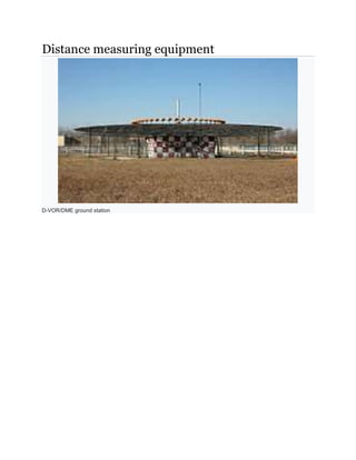
  • 2. DME antenna beside the DME transponder shelter Distance measuring equipment (DME) is a transponder-based radio navigation technology that measures slant range distance by timing the propagation delay of VHF or UHF radio signals. Developed in Australia, it was invented by James "Gerry" Gerrand[1] under the supervision of Edward George "Taffy" Bowen while employed as Chief of the Division of Radiophysics of the Commonwealth Scientific and Industrial Research Organisation (CSIRO). Another engineered version of the system was deployed by Amalgamated Wireless Australasia Limited in the early 1950s operating in the 200 MHz VHF band. This Australian domestic version was referred to by the Federal Department of Civil Aviation as DME(D) (or DME Domestic), and the later international version adopted by ICAO as DME(I). DME is similar to secondary radar, except in reverse. The system was a post-war development of the IFF (identification friend or foe) systems of World War II. To maintain compatibility, DME is functionally identical to the distance measuring component of TACAN.
  • 3. Operation Aircraft use DME to determine their distance from a land-based transponder by sending and receiving pulse pairs – two pulses of fixed duration and separation. The ground stations are typically collocated with VORs or ILS systems. A low-power DME can be collocated with an ILS glide slope antenna installation where it provides an accurate distance to touchdown function, similar to that otherwise provided by ILS marker beacons. A typical Distance measuring equipment ground transponder system for en-route or terminal navigation will have a 1 kW peak pulse output on the assigned UHF channel. Hardware The DME system comprises a UHF transmitter/receiver (interrogator) in the aircraft and a UHF receiver/transmitter (transponder) on the ground. DME distance and VOR/ADF cockpit display instruments Timing SEARCH MODE: 150 interrogation pulse-pairs per second. The aircraft interrogates the ground transponder with a series of pulse-pairs (interrogations) and, after a precise time delay (typically 50 microseconds), the ground station replies with an identical sequence of pulse-pairs. The DME receiver in the aircraft searches for reply pulse-pairs (X-mode= 12 microsecond spacing) with the correct interval and reply pattern to its original interrogation pattern. (Pulse-pairs that are not coincident with the individual aircraft's interrogation pattern e.g. not synchronous, are referred to as filler pulse-pairs, or squitter. Also, replies to other aircraft that are therefore non-synchronous also appear as squitter). TRACK MODE: less than 30 interrogation Pulse-pairs per second, as the average number of pulses in SEARCH and TRACK is limited to max 30 pulse pairs per second. The aircraft interrogator locks on to the DME ground station once it recognizes a particular reply pulse sequence has the same spacing as the original interrogation sequence. Once the receiver is locked on, it has a narrower window in which to look for the echoes and can retain lock.
  • 4. Distance calculation A radio signal takes approximately 12.36 microseconds to travel 1 nautical mile (1,852 m) to the target and back—also referred to as a radar-mile. The time difference between interrogation and reply, minus the 50 microsecond ground transponder delay, is measured by the interrogator's timing circuitry and converted to a distance measurement (slant range), in nautical miles, then displayed on the cockpit DME display. The distance formula, distance = rate * time, is used by the DME receiver to calculate its distance from the DME ground station. The rate in the calculation is the velocity of the radio pulse, which is the speed of light (roughly 300,000,000 m/s or 186,000 mi/s). The time in the calculation is (total time – 50µs)/2. Accuracy The accuracy of DME ground stations is 185 m (±0.1 nmi).[2] It's important to understand that DME provides the physical distance from the aircraft to the DME transponder. This distance is often referred to as 'slant range' and depends trigonometrically upon both the altitude above the transponder and the ground distance from it. For example, an aircraft directly above the DME station at 6,076 ft (1 nmi) altitude would still show 1.0 nmi (1.9 km) on the DME readout. The aircraft is technically a mile away, just a mile straight up. Slant range error is most pronounced at high altitudes when close to the DME station. Radio-navigation aids must keep a certain degree of accuracy, given by international standards, FAA,[3] EASA, ICAO, etc. To assure this is the case, flight inspection organizations check periodically critical parameters with properly equipped aircraft to calibrate and certify DME precision. ICAO recommends accuracy of less than the sum of 0.25 nmi plus 1.25% of the distance measured. Specification A typical DME transponder can provide distance information to 100 to 200 aircraft at a time. Above this limit the transponder avoids overload by limiting the sensitivity of the receiver. Replies to weaker more distant interrogations are ignored to lower the transponder load. Radio frequency and modulation data DME frequencies are paired to VHF omnidirectional range (VOR) frequencies and a DME interrogator is designed to automatically tune to the corresponding DME frequency when the associated VOR frequency is selected. An airplane’s DME interrogator uses frequencies from 1025 to 1150 MHz. DME transponders transmit on a channel in the 962 to 1213 MHz range and receive on a corresponding channel between 1025 and 1150 MHz. The band is divided into 126 channels for interrogation and 126 channels for reply. The interrogation and reply frequencies always differ by 63 MHz. The spacing of all channels is 1 MHz with a signal spectrum width of 100 kHz. Technical references to X and Y channels relate only to the spacing of the individual pulses in the DME pulse pair, 12 microsecond spacing for X channels and 30 microsecond spacing for Y channels. DME facilities identify themselves with a 1,350 Hz Morse code three letter identity. If collocated with a VOR or ILS, it will have the same identity code as the parent facility. Additionally, the DME will identify itself between those of the parent facility. The DME identity is 1,350 Hz to differentiate itself from the 1,020 Hz tone of the VOR or the ILS localizer.
  • 5. Terminal DME A terminal DME, referred to as a TDME in navigational charts, is a DME that is designed to provide a 0 reading at the threshold point of the runway, regardless of the physical location of the equipment. It is typically associated with ILS or other instrument approach. Future DME operation will continue and possibly expand as an alternate navigation source to space-based navigational systems such as