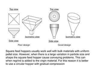
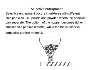
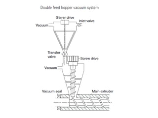
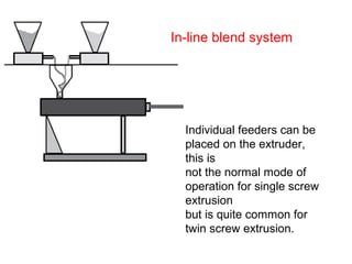
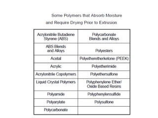
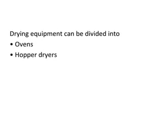
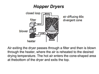
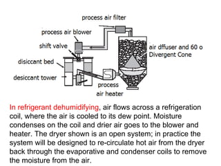
Auxiliary Equipment
1. Feeding system
The two solid feed systems that rely on gravity are
flood and starve feeding. Both feed systems have a hopper
sitting directly over the throat.
The feed throat section, attached directly to the extruder
barrel, is water jacketed for cooling.
The feed throat should feel warm to the touch but not hot.
Flood feeding fills the screw channels completely
and takes advantage of the full length of the
screw. It requires no extra feeding equipment, but
offers reduced process control.
Starve feeding requires a feeder but offers greater process
control and tends to reduce melt temperatures.
Standard feed throat design for pellets or powder is shown
In geometry A.
Feed throat geometries B and C are more appropriate for
melt-fed extruders. Pellets fed can wedge between the
barrel and screw, causing the screw to deflect.
Square feed hoppers usually work well with bulk materials with uniform
pellet size. However, when there is a large variation in particle size and
shape the square feed hopper cause conveying problems. This can
when regrind is added to the virgin material. For this reason it is better
to use a circular hopper with gradual compression
Bridging
Bridging is caused by:
• Compressibility of polymer or additives
in the feed hopper
• Non-free flowing formulations
• Material softening in
the feed throat and adhering
to the feed hopper
• Large chunks of material
(particularly regrind)
• Fibers
• Low bulk density materials
Funneling
Funneling occurs when material is not free
flowing and sticks to the hopper walls. Center
flow in the hopper leaves build up on the hopper
walls.
Selective entrapment
Selective entrapment occurs in mixtures with different
size particles, i.e., pellets and powder, where the particles
can separate. The bottom of the hopper becomes richer in
smaller size particle material, while the top is richer in
large size particle material.
Slippage
Large particle size, lubricants, or liquids can cause
slippage in the feed section. Grinding or pulverizing the
particles to a smaller size can eliminate this problem. Slippage
due to either internal or external lubricants coating the barrel
walls is an issue that is extremely difficult to overcome in
normal operation when lubricants or mold releases are being
compounded.
Force feeding only is possible.
Cutting
Cutting large pellets or regrind chunks between the
screw flight and feed throat is another feed problem.
Ejection
The final feed problem is called ejection;
it is where large rubbery particles can
be ejected or forced out the extruder by
screw rotation.
Gravity feeding and forced feeding
If the extruder feed hopper level changes from
almost empty to full, the throughput rate will change
slightly. This is accompanied by a change in the product dimensions.
In a flood-fed extrusion setup, the material level in the feed
hopper needs to be kept at a fairly constant level.
Feeding system
Belt feeders are low cost, have high
throughput volumes, and are simply
constructed. The rate of the belt speed
and the size of the gate opening
Determine the throughput.
Feeding system.
Extruders typically use either screw, vibratory, or belt
• feeders. Screw conveyors screw with rigid housing
Distance- 60 m
Flow rate -4m3/h
The flexible screw conveyor has a helicoid screw that rotates
inside a fixed tube. Screw conveyors typically range in
diameter from 2½ to 8 in., and can be used for horizontal
transports of up to 80 ft, and inclines of up to 60 degrees. An
8-in.-diam screw conveyor can transport 1800 cu ft/hr at 360
RPM at a 45-degree angle.
Pressure Conveying Unit
The system requires compressed air at 2-6bar. The
compressed air must be free of oil and water.
The level is kept constant by incorporating a vacuum loader,
on top of the feed hopper that adds material to
the feed hopper during operation
.
Suction units
Individual feeders can be
placed on the extruder,
this is
not the normal mode of
operation for single screw
extrusion
but is quite common for
twin screw extrusion.
In-line blend system
Drying
• Certain polymers are hygroscopic in nature,
meaning they absorb moisture from the air
until their equilibrium moisture content is
reached. In general, polar polymer molecules
containing oxygen and/or nitrogen
Drying equipment can be divided into
• Ovens
• Hopper dryers
Oven drying is generally used for small lots.
It is more efficient to use more trays with less resin
in each tray, as the circulating air does not flow between
pellets.
Oven drying
Hopper Dryers
Air exiting the dryer passes through a filter and then is blown
through the heater, where the air is reheated to the desired
drying temperature. The hot air enters the cone-shaped area
at thebottom of the dryer and exits the top.
In refrigerant dehumidifying, air flows across a refrigeration
coil, where the air is cooled to its dew point. Moisture
condenses on the coil and drier air goes to the blower and
heater. The dryer shown is an open system; in practice the
system will be designed to re-circulate hot air from the dryer
back through the evaporative and condenser coils to remove
the moisture from the air.

Hoppers

  • 1.
  • 2.
    The two solidfeed systems that rely on gravity are flood and starve feeding. Both feed systems have a hopper sitting directly over the throat. The feed throat section, attached directly to the extruder barrel, is water jacketed for cooling. The feed throat should feel warm to the touch but not hot.
  • 3.
    Flood feeding fillsthe screw channels completely and takes advantage of the full length of the screw. It requires no extra feeding equipment, but offers reduced process control.
  • 4.
    Starve feeding requiresa feeder but offers greater process control and tends to reduce melt temperatures.
  • 5.
    Standard feed throatdesign for pellets or powder is shown In geometry A. Feed throat geometries B and C are more appropriate for melt-fed extruders. Pellets fed can wedge between the barrel and screw, causing the screw to deflect.
  • 6.
    Square feed hoppersusually work well with bulk materials with uniform pellet size. However, when there is a large variation in particle size and shape the square feed hopper cause conveying problems. This can when regrind is added to the virgin material. For this reason it is better to use a circular hopper with gradual compression
  • 8.
    Bridging Bridging is causedby: • Compressibility of polymer or additives in the feed hopper • Non-free flowing formulations • Material softening in the feed throat and adhering to the feed hopper • Large chunks of material (particularly regrind) • Fibers • Low bulk density materials
  • 9.
    Funneling Funneling occurs whenmaterial is not free flowing and sticks to the hopper walls. Center flow in the hopper leaves build up on the hopper walls.
  • 10.
    Selective entrapment Selective entrapmentoccurs in mixtures with different size particles, i.e., pellets and powder, where the particles can separate. The bottom of the hopper becomes richer in smaller size particle material, while the top is richer in large size particle material.
  • 11.
    Slippage Large particle size,lubricants, or liquids can cause slippage in the feed section. Grinding or pulverizing the particles to a smaller size can eliminate this problem. Slippage due to either internal or external lubricants coating the barrel walls is an issue that is extremely difficult to overcome in normal operation when lubricants or mold releases are being compounded. Force feeding only is possible.
  • 12.
    Cutting Cutting large pelletsor regrind chunks between the screw flight and feed throat is another feed problem.
  • 13.
    Ejection The final feedproblem is called ejection; it is where large rubbery particles can be ejected or forced out the extruder by screw rotation.
  • 14.
    Gravity feeding andforced feeding If the extruder feed hopper level changes from almost empty to full, the throughput rate will change slightly. This is accompanied by a change in the product dimensions. In a flood-fed extrusion setup, the material level in the feed hopper needs to be kept at a fairly constant level.
  • 15.
    Feeding system Belt feedersare low cost, have high throughput volumes, and are simply constructed. The rate of the belt speed and the size of the gate opening Determine the throughput.
  • 16.
    Feeding system. Extruders typicallyuse either screw, vibratory, or belt • feeders. Screw conveyors screw with rigid housing Distance- 60 m Flow rate -4m3/h
  • 17.
    The flexible screwconveyor has a helicoid screw that rotates inside a fixed tube. Screw conveyors typically range in diameter from 2½ to 8 in., and can be used for horizontal transports of up to 80 ft, and inclines of up to 60 degrees. An 8-in.-diam screw conveyor can transport 1800 cu ft/hr at 360 RPM at a 45-degree angle.
  • 18.
    Pressure Conveying Unit Thesystem requires compressed air at 2-6bar. The compressed air must be free of oil and water.
  • 19.
    The level iskept constant by incorporating a vacuum loader, on top of the feed hopper that adds material to the feed hopper during operation .
  • 20.
  • 22.
    Individual feeders canbe placed on the extruder, this is not the normal mode of operation for single screw extrusion but is quite common for twin screw extrusion. In-line blend system
  • 23.
  • 24.
    Drying • Certain polymersare hygroscopic in nature, meaning they absorb moisture from the air until their equilibrium moisture content is reached. In general, polar polymer molecules containing oxygen and/or nitrogen
  • 27.
    Drying equipment canbe divided into • Ovens • Hopper dryers
  • 28.
    Oven drying isgenerally used for small lots. It is more efficient to use more trays with less resin in each tray, as the circulating air does not flow between pellets. Oven drying
  • 29.
    Hopper Dryers Air exitingthe dryer passes through a filter and then is blown through the heater, where the air is reheated to the desired drying temperature. The hot air enters the cone-shaped area at thebottom of the dryer and exits the top.
  • 30.
    In refrigerant dehumidifying,air flows across a refrigeration coil, where the air is cooled to its dew point. Moisture condenses on the coil and drier air goes to the blower and heater. The dryer shown is an open system; in practice the system will be designed to re-circulate hot air from the dryer back through the evaporative and condenser coils to remove the moisture from the air.