SlideShare a Scribd company logo
1 of 51
UNIT I
Definition of Network:
A computer network is a group of computers that use a set of common communication
protocols over digital interconnections for the purpose of sharing resources located on or
provided by the network nodes
1. Personal Area Network (PAN)
2. Local Area Network (LAN)
3. Wireless Local Area Network (WLAN)
4. Campus Area Network (CAN)
5. Metropolitan Area Network (MAN)
6. Wide Area Network (WAN)
7. Storage-Area Network (SAN)
8. System-Area Network (also known as SAN)
Personal Area Network
A Personal Area Network (PAN) is smallest network which is very personal to a user.
This may include Bluetooth enabled devices or infra-red enabled devices. PAN has
connectivity range up to 10 meters. PAN may include wireless computer keyboard and
mouse, Bluetooth enabled headphones, wireless printers and TV remotes.
Local Area Network
A computer network spanned inside a building and operated under single
administrative system is generally termed as Local Area Network (LAN). Usually,LAN
covers an organization’ offices, schools, colleges or universities. Number of systems
connected in LAN may vary from as least as two to as much as 16 million.
LAN provides a useful way of sharing the resources between end users.The resources
such as printers, file servers, scanners, and internet are easily sharable among computers.
Metropolitan Area Network
The Metropolitan Area Network (MAN) generally expands throughout a city such as
cable TV network. It can be in the form of Ethernet,Token-ring, ATM, or Fiber Distributed
Data Interface (FDDI).
Metro Ethernet is a service which is provided by ISPs. This service enables its users
to expand their Local Area Networks. For example, MAN can help an organization to
connect all of its offices in a city.
Wide Area Network
Wide Area Network (WAN) covers a wide area which may span across provinces and
even a whole country. Generally, telecommunication networks are Wide Area Network.
These networks provide connectivity to MANs and LANs. Since they are equipped with very
high speed backbone, WANs use very expensive network equipment.
Campus Area Network
A campus network, campus area network, corporate area network or CAN is a computer
network made up of an interconnection of local area networks within a limited geographical
area
A storage area network (SAN)
It is a dedicated high-speed network or subnetwork that interconnects and presents
shared pools of storage devices to multiple servers. A SAN moves storage resources off the
common user network and reorganizes them into an independent, high-performance network.
A wireless local area network (WLAN)
It is a wireless distribution method for two or more devices that use high-frequency
radio waves and often include an access point to the Internet. A WLAN allows users to move
around the coverage area, often a home or small office, while maintaining a network
connection
system area network (SAN)
It is a high-performance, connection-oriented network that can link a cluster of
computers. A SAN delivers high bandwidth (1 Gbps or greater) with low latency. A SAN is
typically switched by hubs that support eight or more nodes.
TOPOLOGY
The arrangements of nodes or systems called Topology. Topology can be classified in
to five categories
 Bus Topology
 Star Topology
 Ring Topology
 Mesh Topoogy
 Tree Topology
BUS Topology
Bus topology is a network type in which every computer and network device is connected to
single cable. When it has exactly two endpoints, then it is called Linear Bus topology.
Features of Bus Topology
 It transmits data only in one direction.
 Every device is connected to a single cable
Advantages of Bus Topology
 It is cost effective.
 Cable required is least compared to other network topology.
 Used in small networks.
 It is easy to understand.
 Easy to expand joining two cables together.
Disadvantages of Bus Topology
 Cables fails then whole network fails.
 If network traffic is heavy or nodes are more the performance of the network
decreases.
 Cable has a limited length.
 It is slower than the ring topology.
RING Topology
It is called ring topology because it forms a ring as each computer is connected to another
computer, with the last one connected to the first. Exactly two neighbours for each device.
Features of Ring Topology
 A number of repeaters are used for Ring topology with large number of nodes,
because if someone wants to send some data to the last node in the ring topology with
100 nodes, then the data will have to pass through 99 nodes to reach the 100th node.
Hence to prevent data loss repeaters are used in the network.
 The transmission is unidirectional, but it can be made bidirectional by having 2
connections between each Network Node, it is called Dual Ring Topology.
 In Dual Ring Topology, two ring networks are formed, and data flow is in opposite
direction in them. Also, if one ring fails, the second ring can act as a backup, to keep
the network up.
 Data is transferred in a sequential manner that is bit by bit. Data transmitted, has to
pass through each node of the network, till the destination node.
Advantages of Ring Topology
 Transmitting network is not affected by high traffic or by adding more nodes, as only
the nodes having tokens can transmit data.
 Cheap to install and expand
Disadvantages of Ring Topology
 Troubleshooting is difficult in ring topology.
 Adding or deleting the computers disturbs the network activity.
 Failure of one computer disturbs the whole network.
STAR Topology
In this type of topology all the computers are connected to a single hub through a cable. This
hub is the central node and all others nodes are connected to the central node.
Features of Star Topology
Every node has its own dedicated connection to the hub.
 Hub acts as a repeater for data flow.
 Can be used with twisted pair, Optical Fibre or coaxial cable.
Advantages of Star Topology
 Fast performance with few nodes and low network traffic.
 Hub can be upgraded easily.
 Easy to troubleshoot.
 Easy to setup and modify.
 Only that node is affected which has failed, rest of the nodes can work smoothly.
Disadvantages of Star Topology
 Cost of installation is high.
 Expensive to use.
 If the hub fails then the whole network is stopped because all the nodes depend on the
hub.
 Performance is based on the hub that is it depends on its capacity
MESH Topology
It is a point-to-point connection to other nodes or devices. All the network nodes are
connected to each other. Mesh has n(n-1)/2 physical channels to link n devices.
There are two techniques to transmit data over the Mesh topology, they are :
 Routing
 Flooding
MESH Topology: Routing
In routing, the nodes have a routing logic, as per the network requirements. Like routing logic
to direct the data to reach the destination using the shortest distance. Or, routing logic which
has information about the broken links, and it avoids those node etc. We can even have
routing logic, to re-configure the failed nodes.
MESH Topology: Flooding
In flooding, the same data is transmitted to all the network nodes, hence no routing logic is
required. The network is robust, and the its very unlikely to lose the data. But it leads to
unwanted load over the network.
Types of Mesh Topology
Partial Mesh Topology :
In this topology some of the systems are connected in the same fashion as mesh
topology but some devices are only connected to two or three devices.
Full Mesh Topology :
Each and every nodes or devices are connected to each other.
Features of Mesh Topology
 Fully connected.
 Robust.
 Not flexible.
Advantages of Mesh Topology
 Each connection can carry its own data load.
 It is robust.
 Fault is diagnosed easily.
 Provides security and privacy.
Disadvantages of Mesh Topology
 Installation and configuration is difficult.
 Cabling cost is more.
 Bulk wiring is required.
TREE Topology
It has a root node and all other nodes are connected to it forming a hierarchy. It is also
called hierarchical topology. It should at least have three levels to the hierarchy.
Features of Tree Topology
 Ideal if workstations are located in groups.
 Used in Wide Area Network.
Advantages of Tree Topology
 Extension of bus and star topologies.
 Expansion of nodes is possible and easy.
 Easily managed and maintained.
 Error detection is easily done.
Disadvantages of Tree Topology
 Heavily cabled.
 Costly.
 If more nodes are added maintenance is difficult.
 Central hub fails, network fails.
HYBRID Topology
It is two different types of topologies which is a mixture of two or more topologies.
For example if in an office in one department ring topology is used and in another star
topology is used, connecting these topologies will result in Hybrid Topology (ring topology
and star topology).
Features of Hybrid Topology
 It is a combination of two or topologies
 Inherits the advantages and disadvantages of the topologies included
Advantages of Hybrid Topology
 Reliable as Error detecting and trouble shooting is easy.
 Effective.
 Scalable as size can be increased easily.
 Flexible.
Disadvantages of Hybrid Topology
 Complex in design.
 Costly.
Layers of OSI Model
OSI stands for Open Systems Interconnection. It has been developed by ISO –
‘International Organization of Standardization‘, in the year 1984. It is a 7 layer architecture
with each layer having specific functionality to perform. All these 7 layers work
collaboratively to transmit the data from one person to another across the globe.
1. Physical Layer (Layer 1) :
The lowest layer of the OSI reference model is the physical layer. It is responsible for the
actual physical connection between the devices. The physical layer contains information in
the form of bits. It is responsible for transmitting individual bits from one node to the next.
When receiving data, this layer will get the signal received and convert it into 0s and 1s and
send them to the Data Link layer, which will put the frame back together.
The functions of the physical layer are :
Bit synchronization: The physical layer provides the synchronization of the bits by
providing a clock. This clock controls both sender and receiver thus providing
synchronization at bit level.
Bit rate control: The Physical layer also defines the transmission rate i.e. the number of bits
sent per second.
Physical topologies: Physical layer specifies the way in which the different, devices/nodes are
arranged in a network i.e. bus, star or mesh topolgy.
Transmission mode: Physical layer also defines the way in which the data flows between the
two connected devices. The various transmission modes possible are: Simplex, half-duplex
and full-duplex.
* Hub, Repeater, Modem, Cables are Physical Layer devices.
** Network Layer, Data Link Layer and Physical Layer are also known as Lower Layers or
Hardware Layers.
Functions of Physical Layer
Following are the various functions performed by the Physical layer of the OSI model.
Representation of Bits: Data in this layer consists of stream of bits. The bits must be
encoded into signals for transmission. It defines the type of encoding i.e. how 0's and 1's are
changed to signal.
Data Rate: This layer defines the rate of transmission which is the number of bits per
second.
Synchronization: It deals with the synchronization of the transmitter and receiver. The
sender and receiver are synchronized at bit level.
Interface: The physical layer defines the transmission interface between devices and
transmission medium.
Line Configuration: This layer connects devices with the medium: Point to Point
configuration and Multipoint configuration.
Topologies: Devices must be connected using the following topologies: Mesh, Star, Ring and
Bus.
Transmission Modes: Physical Layer defines the direction of transmission between two
devices: Simplex, Half Duplex, Full Duplex.
Deals with baseband and broadband transmission.
2. Data Link Layer (DLL) (Layer 2) :
The data link layer is responsible for the node to node delivery of the message. The main
function of this layer is to make sure data transfer is error-free from one node to another, over
the physical layer. When a packet arrives in a network, it is the responsibility of DLL to
transmit it to the Host using its MAC address.
Data Link Layer is divided into two sub layers :
 Logical Link Control (LLC)
 Media Access Control (MAC)
The packet received from Network layer is further divided into frames depending on the
frame size of NIC(Network Interface Card). DLL also encapsulates Sender and Receiver’s
MAC address in the header.
The Receiver’s MAC address is obtained by placing an ARP(Address Resolution Protocol)
request onto the wire asking “Who has that IP address?” and the destination host will reply
with its MAC address.
The functions of the data Link layer are :
Framing: Framing is a function of the data link layer. It provides a way for a sender to
transmit a set of bits that are meaningful to the receiver. This can be accomplished by
attaching special bit patterns to the beginning and end of the frame.
Physical addressing: After creating frames, Data link layer adds physical addresses (MAC
address) of sender and/or receiver in the header of each frame.
Error control: Data link layer provides the mechanism of error control in which it detects
and retransmits damaged or lost frames.
Flow Control: The data rate must be constant on both sides else the data may get corrupted
thus , flow control coordinates that amount of data that can be sent before receiving
acknowledgement.
Access control: When a single communication channel is shared by multiple devices, MAC
sub-layer of data link layer helps to determine which device has control over the channel at a
given time.
Types of framing – There are two types of framing:
1. Fixed size – The frame is of fixed size and there is no need to provide boundaries to the
frame, length of the frame itself acts as delimiter.
Drawback: It suffers from internal fragmentation if data size is less than frame size
Solution: Padding
2. Variable size – In this there is need to define end of frame as well as beginning of next
frame to distinguish. This can be done in two ways:
Length field –introduce a length field in the frame to indicate the length of the frame. Used
in Ethernet(802.3). The problem with this is that sometimes the length field might get
corrupted.
End Delimeter (ED) –introduce an ED(pattern) to indicate the end of the frame. Used in
Token Ring. The problem with this is that ED can occur in the data. This can be solved by:
3. Network Layer (Layer 3) :
Network layer works for the transmission of data from one host to the other located in
different networks. It also takes care of packet routing i.e. selection of the shortest path to
transmit the packet, from the number of routes available. The sender & receiver’s IP address
are placed in the header by the network layer.
The functions of the Network layer are :
Routing: The network layer protocols determine which route is suitable from source to
destination. This function of network layer is known as routing.
Logical Addressing: In order to identify each device on internetwork uniquely, network
layer defines an addressing scheme. The sender & receiver’s IP address are placed in the
header by network layer. Such an address distinguishes each device uniquely and universally.
* Segment in Network layer is referred as Packet.
Network Layer Features
With its standard functionalities, Layer 3 can provide various features as:
 Quality of service management
 Load balancing and link management
 Security
 Interrelation of different protocols and subnets with different schema.
 Different logical network design over the physical network design.
4. Transport Layer (Layer 4) :
Transport layer provides services to application layer and takes services from network layer.
The data in the transport layer is referred to as Segments. It is responsible for the End to End
Delivery of the complete message. The transport layer also provides the acknowledgement of
the successful data transmission and re-transmits the data if an error is found.
• At sender’s side:
 Transport layer receives the formatted data from the upper layers, performs
Segmentation and also implements Flow & Error control to ensure proper data
transmission.
 It also adds Source and Destination port number in its header and forwards the
segmented data to the Network Layer.
Note: The sender need to know the port number associated with the receiver’s application.
 Generally, this destination port number is configured, either by default or manually.
For example, when a web application makes a request to a web server, it typically
uses port number 80, because this is the default port assigned to web applications.
Many applications have default port assigned.

• At receiver’s side:
 Transport Layer reads the port number from its header and forwards the Data which it
has received to the respective application. It also performs sequencing and
reassembling of the segmented data.

The functions of the transport layer are :
Segmentation and Reassembly: This layer accepts the message from the (session) layer ,
breaks the message into smaller units . Each of the segment produced has a header associated
with it. The transport layer at the destination station reassembles the message.
Service Point Addressing: In order to deliver the message to correct process, transport layer
header includes a type of address called service point address or port address. Thus by
specifying this address, transport layer makes sure that the message is delivered to the correct
process.
The services provided by the transport layer :
Connection Oriented Service: It is a three-phase process which include
 Connection Establishment
 Data Transfer
 Termination / disconnection
In this type of transmission, the receiving device sends an acknowledgement, back to the
source after a packet or group of packet is received. This type of transmission is reliable and
secure.
Connection less service: It is a one-phase process and includes Data Transfer. In this type of
transmission, the receiver does not acknowledge receipt of a packet. This approach allows for
much faster communication between devices. Connection-oriented service is more reliable
than connectionless Service.
* Data in the Transport Layer
Transport layer is operated by the Operating System. It is a part of the OS and communicates
with the Application Layer by making system calls.
Transport Layer is called as Heart of OSI model.is called as Segments.
5. Session Layer (Layer 5) :
This layer is responsible for establishment of connection, maintenance of sessions,
authentication and also ensures security.
The functions of the session layer are :
Session establishment, maintenance and termination: The layer allows the two processes
to establish, use and terminate a connection.
Synchronization : This layer allows a process to add checkpoints which are considered as
synchronization points into the data. These synchronization point help to identify the error so
that the data is re-synchronized properly, and ends of the messages are not cut prematurely
and data loss is avoided.
Dialog Controller : The session layer allows two systems to start communication with each
other in half-duplex or full-duplex.
**All the below 3 layers(including Session Layer) are integrated as a single layer in the
TCP/IP model as “Application Layer”.
**Implementation of these 3 layers is done by the network application itself. These are also
known as Upper Layers or Software Layers.
6. Presentation Layer (Layer 6) :
Presentation layer is also called the Translation layer.The data from the application layer is
extracted here and manipulated as per the required format to transmit over the network.
The functions of the presentation layer are :
Translation : For example, ASCII to EBCDIC.
Encryption/ Decryption : Data encryption translates the data into another form or code. The
encrypted data is known as the cipher text and the decrypted data is known as plain text. A
key value is used for encrypting as well as decrypting data.
Compression: Reduces the number of bits that need to be transmitted on the network.
7. Application Layer (Layer 7) :
At the very top of the OSI Reference Model stack of layers, we find Application layer which
is implemented by the network applications. These applications produce the data, which has
to be transferred over the network. This layer also serves as a window for the application
services to access the network and for displaying the received information to the user.
Ex: Application – Browsers, Skype Messenger etc.
**Application Layer is also called as Desktop Layer.
The functions of the Application layer are :
 Network Virtual Terminal
 FTAM-File transfer access and management
 Mail Services
 Directory Services
OSI model acts as a reference model and is not implemented in the Internet because of its late
invention. Current model being used is the TCP/IP model.
I NETWORK LAYER
The Network Layer is the third layer of the OSI model. It handles the service requests from
the transport layer and further forwards the service request to the data link layer. The network
layer translates the logical addresses into physical addresses.
Functions of Network Layer
Devices which work on Network Layer mainly focus on routing. Routing may include
various tasks aimed to achieve a single goal. These can be:
 Addressing devices and networks.
 Populating routing tables or static routes.
 Queuing incoming and outgoing data and then forwarding them according to quality
of service constraints set for those packets.
 Internetworking between two different subnets.
 Delivering packets to destination with best efforts.
 Provides connection oriented and connection less mechanism.
Network Layer Features
With its standard functionalities, Layer 3 can provide various features as:
 Quality of service management
 Load balancing and link management
 Security
 Interrelation of different protocols and subnets with different schema.
 Different logical network design over the physical network design.
 L3 VPN and tunnels can be used to provide end to end dedicated
connectivity.
1.1ROUTING ALGORITHMS:
Types of Routing
Routing is a process which is performed by layer 3 (or network layer) devices in order
to deliver the packet by choosing an optimal path from one network to another.
There are 3 types of routing:
1. Static Routing
2. Default Routing
3. Dynamic Routing
1. Static routing
Static routing is a process in which we have to manually add routes in routing
table.
Advantages
 No routing overhead for router CPU which means a cheaper router can be
used to do routing.
 It adds security because only administrator can allow routing to particular
networks only.
 No bandwidth usage between routers.
Disadvantage
 For a large network, it is a hectic task for administrator to manually add each
route for the network in the routing table on each router.
 The administrator should have good knowledge of the topology. If a new
administrator comes, then he has to manually add each route so he should have
very good knowledge of the routes of the topology.
2. Default Routing
 This is the method where the router is configured to send all packets towards a single
router (next hop).
 It doesn’t matter to which network the packet belongs, it is forwarded out to router
which is configured for default routing.
 It is generally used with stub routers. A stub router is a router which has only one
route to reach all other networks.
3. Dynamic Routing –
Dynamic routing makes automatic adjustment of the routes according to the current state of
the route in the routing table. Dynamic routing uses protocols to discover network
destinations and the routes to reach it. RIP and OSPF are the best examples of dynamic
routing protocol. Automatic adjustment will be made to reach the network destination if one
route goes down.
3.Dynamic Protocol
A dynamic protocol have following features:
 The routers should have the same dynamic protocol running in order to exchange
routes.
 When a router finds a change in the topology then router advertises it to all other
routers.
Advantages
 Easy to configure.
 More effective at selecting the best route to a destination remote network and also for
discovering remote network.
Disadvantage
 Consumes more bandwidth for communicating with other neighbors.
 Less secure than static routing.
Routing Protocols:
The Protocols are
RIP Routing Information Protocol
OSPFOpen Shortest Path
BGPBorder Gateway Protocol
RIP:
III CONGESTION CONTROL ALGORITHMS:
What is congestion?
A state occurring in network layer when the message traffic is so heavy that it slows
down network response time.
Effects of Congestion
 As delay increases, performance decreases.
 If delay increases, retransmission occurs, making situation worse.
 Congestion control algorithms
Congestion Control Technique:
Open Loop Congestion Control- Open loop congestion control policies are applied to
prevent congestion before it happens. The congestion control is handled either by the source
or the destination.
Closed Loop Congestion Control- Closed-loop congestion control mechanisms try to
alleviate congestion after it happens. Several mechanisms have been used by different
protocols.
Leaky Bucket Algorithm
Let us consider an example to understand
Imagine a bucket with a small hole in the bottom.No matter at what rate water enters
the bucket, the outflow is at constant rate.When the bucket is full with water additional water
entering spills over the sides and is lost.
Figure(A)
Leaky Bucket
Similarly, each network interface contains a leaky bucket and the following steps are
involved in
 leaky bucket algorithm:
When host wants to send packet, packet is thrown into the bucket.
The bucket leaks at a constant rate, meaning the network interface transmits packets at a
constant rate.
Bursty traffic is converted to a uniform traffic by the leaky bucket.
In practice the bucket is a finite queue that outputs at a finite rate.
 Token bucket Algorithm
Need of token bucket Algorithm:-
The leaky bucket algorithm enforces output pattern at the average rate, no matter how bursty
the traffic is. So in order to deal with the bursty traffic we need a flexible algorithm so that
the data is not lost. One such algorithm is token bucket algorithm.
 Steps of this algorithm can be described as follows:
 In regular intervals tokens are thrown into the bucket. ƒ
 The bucket has a maximum capacity. ƒ
 If there is a ready packet, a token is removed from the bucket, and the packet is sent.
 If there is no token in the bucket, the packet cannot be sent.
 Ways in which token bucket is superior to leaky bucket:
The leaky bucket algorithm controls the rate at which the packets are introduced in the
network, but it is very conservative in nature. Some flexibility is introduced in the token
bucket algorithm. In the token bucket, algorithm tokens are generated at each tick (up to a
certain limit). For an incoming packet to be transmitted, it must capture a token and the
transmission takes place at the same rate. Hence some of the busty packets are transmitted at
the same rate if tokens are available and thus introduces some amount of flexibility in the
system.
Formula: M * s = C + ρ * s
where S – is time taken
M – Maximum output rate
ρ – Token arrival rate
C – Capacity of the token bucket in byte
Figure(b)
Let’s understand with an example,
In figure (A) we see a bucket holding three tokens, with five packets waiting to be
transmitted. For a packet to be transmitted, it must capture and destroy one token. In figure
(B) We see that three of the five packets have gotten through, but the other two are stuck
waiting for more tokens to be generated.
Transmission Control Protocol (TCP)
TCP is a connection oriented protocol and offers end-to-end packet delivery. It
acts as back bone for connection.It exhibits the following key features:
 Transmission Control Protocol (TCP) corresponds to the Transport Layer of
OSI Model.
 TCP is a reliable and connection oriented protocol.
TCP offers:
 Stream Data Transfer.
 Reliability.
 Efficient Flow Control
 Full-duplex operation.
 Multiplexing.
 TCP offers connection oriented end-to-end packet delivery.
 TCP ensures reliability by sequencing bytes with a forwarding acknowledgement
number that indicates to the destination the next byte the source expect to
receive.
 It retransmits the bytes not acknowledged with in specified time period.
TCP Services
 TCP offers following services to the processes at the application layer:
 Stream Delivery Service
 Sending and Receiving Buffers
 Bytes and Segments
 Full Duplex Service
 Connection Oriented Service
 Reliable Service
Stream Deliver Service
TCP protocol is stream oriented because it allows the sending process to send data as
stream of bytes and the receiving process to obtain data as stream of bytes.
Sending and Receiving Buffers
It may not be possible for sending and receiving process to produce and obtain data at
same speed, therefore, TCP needs buffers for storage at sending and receiving ends.
Bytes and Segments
The Transmission Control Protocol (TCP), at transport layer groups the bytes into a
packet. This packet is called segment. Before transmission of these packets, these
segments are encapsulated into an IP datagram.
Full Duplex Service
Transmitting the data in duplex mode means flow of data in both the directions at the
same time.
Connection Oriented Service
TCP offers connection oriented service in the following manner:
 TCP of process-1 informs TCP of process – 2 and gets its approval.
 TCP of process – 1 and TCP of process – 2 and exchange data in both the two
directions.
 After completing the data exchange, when buffers on both sides are empty, the
two TCP’s destroy their buffers.
Reliable Service
For sake of reliability, TCP uses acknowledgement mechanism.
Features of Transport Layer
 The protocol layer just above the Internet Layer is the Host-to-Host Transport Layer.
 This name is usually shortened to Transport Layer. The two most important protocols
in the
 Transport Layer are Transmission Control Protocol (TCP) and User Datagram
Protocol (UDP).
 TCP provides reliable data delivery service with end-to-end error detection and
correction. UDP provides low-overhead, connectionless datagram delivery service.
 Both protocols deliver data between the Application Layer and the Internet Layer.
Applications programmers can choose whichever service is more appropriate for their
specific applications.
User Datagram Protocol
 The User Datagram Protocol gives application programs direct access to a datagram
delivery service, like the delivery service that IP provides.
 This allows applications to exchange messages over the network with a minimum of
protocol overhead.
 UDP is an unreliable, connectionless datagram protocol. As noted previously,
"unreliable" merely means that there are no techniques in the protocol for verifying
that the data reached the other end of the network correctly.
UDP message format
1.6.2 Transmission Control Protocol
Applications that require the transport protocol to provide reliable data delivery use TCP
because it verifies that data is delivered across the network accurately and in the proper
sequence. TCP is a reliable, connection-oriented, byte-stream protocol. Let's look at each of
the terms - reliable, connection-oriented, and byte-stream - in more detail.
TCP segment format
 TCP is connection-oriented. It establishes a logical end-to-end connection between
the two communicating hosts. Control information, called a handshake, is exchanged
between the two endpoints to establish a dialogue before data is transmitted.
 TCP indicates the control function of a segment by setting the appropriate bit in the
Flags field in word 4 of the segment header.
 The type of handshake used by TCP is called a three-way handshake because three
segments are exchanged.
 It shows the simplest form of the three-way handshake. Host A begins the connection
by sending host B a segment with the "Synchronize sequence numbers" (SYN) bit set.
 This segment tells host B that A wishes to set up a connection, and it tells B what
sequence number host A will use as a starting number for its segments. (Sequence
numbers are used to keep data in the proper order.)
 Host B responds to A with a segment that has the "Acknowledgment" (ACK) and
SYN bits set. B's segment acknowledges the receipt of A's segment, and informs A
which Sequence Number host B will start with. Finally, host A sends a segment that
acknowledges receipt of B's segment, and transfers the first actual data.
Three-way handshake
 The Acknowledgment Segment (ACK) performs two functions: positive
acknowledgment and flow control.
 The acknowledgment tells the sender how much data has been received, and how
much more the receiver can accept.
 The Acknowledgment Number is the sequence number of the next byte the receiver
expects to receive.
 The standard does not require an individual acknowledgment for every packet. The
acknowledgment number is a positive acknowledgment of all bytes up to that number.
UNIT V
Application Layer Protocols (DNS, SMTP, POP, FTP, HTTP) Study Notes
An application layer protocol defines how application processes (clients and servers),
running on different end systems, pass messages to each other. In particular, an application
layer protocol defines
 The types of messages, e.g., request messages and response messages.
 The syntax of the various message types, i.e., the fields in the message and how the
fields are delineated.
 The semantics of the fields, i.e., the meaning of the information that the field is
supposed to contain
Rules for determining when and how a process sends messages and responds to
messages.
1 SMTP (Simple Mail Transfer Protocol):(E-Mail)
 One of the most popular network service is electronic mail (e-mail).
 The TCP/IP protocol that supports electronic mail on the Internet is called Simple
Mail Transfer Protocol (SMTP).
 SMTP transfers messages from senders' mail servers to the recipients' mail servers
using TCP connections.
 Users based on e-mail addresses.
 MTP provides services for mail exchange between users on the same or different
computers.
Following the client/server model:
 SMTP has two sides: a client side which executes on a sender's mail server, and
server side which executes on recipient's mail server.
 Both the client and server sides of SMTP run on every mail server.
 When a mail server sends mail (to other mail servers), it acts as an SMTP client.
 When a mail server receives mail (from other mail servers) it acts as an SMTP server.
TELNET (Terminal Network):
 TELNET is client-server application that allows a user to log onto remote machine
and lets the user to access any application program on a remote computer.
 TELNET uses the NVT (Network Virtual Terminal) system to encode characters on
the local system.
 On the server (remote) machine, NVT decodes the characters to a form acceptable to
the remote machine.
 TELNET is a protocol that provides a general, bi-directional, eight-bit byte oriented
communications facility.
 Many application protocols are built upon the TELNET protocol.
 Telnet services are used on PORT 23.
FTP (File Transfer Protocol):
 FTP is the standard mechanism provided by TCP/IP for copying a file from one host
to another.
 FTP differs form other client-server applications because it establishes 2 connections
between hosts.
 Two connections are: Data Connection and Control Connection.
 Data Connection uses PORT 20 for the purpose and control connection uses PORT 21
for the purpose.
 FTP is built on a client-server architecture and uses separate control and data
connections between the client and the server.
 One connection is used for data transfer, the other for control information (commands
and responses).
 It transfer data reliably and efficiently.
Multipurpose Internet Mail Extensions (MIME):
 It is an extension of SMTP that allows the transfer of multimedia messages.
 If binary data is included in a message MIME headers are used to inform the
receiving mail agent:
1. Content-Transfer-Encoding: Header alerts the receiving user agent that the message
body has been ASCII encoded and the type of encoding used.
2. Content-Type: Header informs the receiving mail agent about the type of data
included in the message.
POP (Post Office Protocol):
 POP is also called as POP3 protocol.
 This is a protocol used by a mail server in conjunction with SMTP to receive and
holds mail for hosts.
 POP3 mail server receives e-mails and filters them into the appropriate user folders.
When a user connects to the mail server to retrieve his mail, the messages are
downloaded from mail server to the user's hard disk.
HTTP (Hypertext Transfer Protocol):
 This is a protocol used mainly to access data on the World Wide Web (www).
 The Hypertext Transfer Protocol (HTTP) the Web's main application-layer protocol
although current browsers can access other types of servers.
 A respository of information spread all over the world and linked together.
 The HTIP protocol transfer data in the form of plain text, hyper text, audio, video and
so on.
 HTTP utilizes TCP connections to send client requests and server replies.
 it is a synchronous protocol which works by making both persistent and non
persistent connections.
Domain Name System (DNS):
 To identify an entity, TCP/IP protocol uses the IP address which uniquely identifies
the connection of a host to the Internet.
 DNS is a hierarchical system, based on a distributed database, that uses a hierarchy of
Name Servers to resolve Internet host names into the corresponding IP addresses
required for packet routing by issuing a DNS query to a name server.
In TCP/IP, this is the domain name system.
 DNS in the Internet: DNS is protocol that can be used in different platforms.
Domain name space is divided into three categories.
 Generic Domain: The generic domain defines registered hosts according, to their
generic behaviour. Each node in the tree defines a domain which is an index to the
domain name space database.
 Country Domain: The country domain section follows the same format as the generic
domain but uses 2 characters country abbreviations (e.g., US for United States) in
place of 3 characters.
 Inverse Domain: The inverse domain is used to map an address to a name.
Domain Names
Domain Name is a symbolic string associated with an IP address. There are several domain
names available; some of them are generic such as com, edu, gov, net etc, while some
country level domain names such as au, in, za, us etc.
The following table shows the Generic Top-Level Domain names:
Domain Name Meaning
Com Commercial business
Edu Education
Gov U.S. government agency
Int International entity
Mil U.S. military
Net Networking organization
Org Non profit organization
Network Security:
Network security consists of the policies and practices adopted to prevent and monitor
unauthorized access, misuse, modification, or denial of a computer network and network-
accessible resources.
Types of Network Security Devices
Active Devices
These security devices block the surplus traffic. Firewalls, antivirus scanning devices,
and content filtering devices are the examples of such devices.
Passive Devices
These devices identify and report on unwanted traffic, for example, intrusion
detection appliances.
Preventative Devices
These devices scan the networks and identify potential security problems. For
example, penetration testing devices and vulnerability assessment appliances.
Unified Threat Management (UTM)
These devices serve as all-in-one security devices. Examples include firewalls,
content filtering, web caching, etc.
Features of Network Security:
Access Control:
This is done through Network Access Control which ensures that only a handful of
authorized personnel must be able to work with allowed amount of resources.
Antivirus and Anti-malware Software:
This type of network security ensures that any malicious software does not enter the
network and jeopardize the security of the data. The malicious software like Viruses, Trojans,
Worms are handled by the same.
Cloud Security:
This data must be protected an it should be ensured that this protection is not
jeopardize over anything. Many businesses embrace SaaS applications for providing some of
its employees the allowance of accessing the data stored over the cloud. This type of security
ensures in creating gaps in visibility of the data.
CRYPTOGRAPHY
 Cryptography is the study and practice of techniques for secure communication in the
presence of third parties called adversaries.
 It deals with developing and analyzing protocols which prevents malicious third
parties from retrieving information being shared between two entities thereby
following the various aspects of information security.
 Secure Communication refers to the scenario where the message or data shared
between two parties can’t be accessed by an adversary.
 In Cryptography, an Adversary is a malicious entity, which aims to retrieve precious
information or data thereby undermining the principles of information security.
 Data Confidentiality, Data Integrity, Authentication and Non-repudiation are
core principles of modern-day cryptography.
 Confidentiality refers to certain rules and guidelines usually executed under
confidentiality agreements which ensure that the information is restricted to certain
people or places.
 Data integrity refers to maintaining and making sure that the data stays accurate and
consistent over its entire life cycle.
 Authentication is the process of making sure that the piece of data being claimed by
the user belongs to it.
 Non-repudiation refers to ability to make sure that a person or a party associated
with a contract or a communication cannot deny the authenticity of their signature
over their document or the sending of a message.
Consider two parties Alice and Bob. Now, Alice wants to send a message m to Bob over a
secure channel.
So, what happens is as follows.
The sender’s message or sometimes called the Plaintext, is converted into an unreadable form
using a Key k. The resultant text obtained is called the Ciphertext. This process is known as
Encryption. At the time of receival, the Ciphertext is converted back into the plaintext using
the same Key k, so that it can be read by the receiver. This process is known as Decryption.
Alice (Sender) Bob (Receiver)
C = E (m, k) ----> m = D (C, k)
Here, C refers to the Ciphertext while E and D are the Encryption and Decryption algorithms
respectively.Let’s consider the case of Caesar Cipher or Shift Cipher as an example.
As the name suggests, in Caesar Cipher each character in a word is replaced by another
character under some defined rules. Thus, if A is replaced by D, B by E and so on. Then, each
character in the word would be shifted by a position of 3. For example:
Plaintext : Geeksforgeeks
Ciphertext : Jhhnvirujhhnv
Cryptography Techniques-
Cryptography techniques may be classified as-
 Symmetric Key Cryptography
 Asymmetric Key Cryptography
Symmetric Key Cryptography-
In this technique,Both sender and receiver uses a common key to encrypt and decrypt the
message.
This secret key is known only to the sender and to the receiver. It is also called as secret key
cryptography.
Working-
The message exchange using symmetric key cryptography involves the following steps-
 Before starting the communication, sender and receiver shares the secret key.
 This secret key is shared through some external means.
 At sender side, sender encrypts the message using his copy of the key.
 The cipher text is then sent to the receiver over the communication channel.
 At receiver side, receiver decrypts the cipher text using his copy of the key.
 After decryption, the message converts back into readable format.
Symmetric Encryption Algorithms-
Some of the encryption algorithms that use symmetric key are-
 Advanced Encryption Standard (AES)
 Data Encryption Standard (DES)
Advantages-
The advantages of symmetric key algorithms are-
 They are efficient.
 They take less time to encrypt and decrypt the message.
UNIT III
I DATALINK LAYER
 Data Link Layer is second layer of OSI Layered Model. This layer is one of
the most complicated layers and has complex functionalities and liabilities.
Data link layer hides the details of underlying hardware and represents itself to
upper layer as the medium to communicate.
 Data link layer works between two hosts which are directly connected in some
sense. This direct connection could be point to point or broadcast. Systems on
broadcast network are said to be on same link. The work of data link layer
tends to get more complex when it is dealing with multiple hosts on single
collision domain.
 Data link layer is responsible for converting data stream to signals bit by bit
and to send that over the underlying hardware. At the receiving end, Data link
layer picks up data from hardware which are in the form of electrical signals,
assembles them in a recognizable frame format, and hands over to upper layer.
Data link layer has two sub-layers:
Logical Link Control: It deals with protocols, flow-control, and error control
Media Access Control: It deals with actual control of media
Functionality of Data-link Layer
Data link layer does many tasks on behalf of upper layer. These are:
Framing
Data-link layer takes packets from Network Layer and encapsulates them into
Frames.Then, it sends each frame bit-by-bit on the hardware. At receiver’ end, data link layer
picks up signals from hardware and assembles them into frames.
Addressing
Data-link layer provides layer-2 hardware addressing mechanism. Hardware address
is assumed to be unique on the link. It is encoded into hardware at the time of manufacturing.
Synchronization
When data frames are sent on the link, both machines must be synchronized in order
to transfer to take place.
Error Control
Sometimes signals may have encountered problem in transition and the bits are
flipped.These errors are detected and attempted to recover actual data bits. It also provides
error reporting mechanism to the sender.
Flow Control
Stations on same link may have different speed or capacity. Data-link layer ensures
flow control that enables both machine to exchange data on same speed.
Multi-Access
When host on the shared link tries to transfer the data, it has a high probability of
collision. Data-link layer provides mechanism such as CSMA/CD to equip capability of
accessing a shared media among multiple Systems.
II Error Detection & Correction
 There are many reasons such as noise, cross-talk etc.,
 It may help data to get corrupted during transmission.
 The upper layers work on some generalized view of network architecture and are not
aware of actual hardware data processing.Hence,
 The upper layers expect error-free transmission between the systems. Most of the
applications would not function expectedly if they receive erroneous data.
 Data-link layer uses some error control mechanism to ensure that frames (data bit
streams) are transmitted with certain level of accuracy. But to understand how errors
is controlled, it is essential to know what types of errors may occur.
Types of Errors
There may be three types of errors:
 Single bit error
 Multiple bits error
 Burst error
 Error Control
Single bit error
In a frame, there is only one bit, anywhere though, which is corrupt.
Multiple bits error
Frame is received with more than one bits in corrupted state.
Burst error
Frame contains more than1 consecutive bits corrupted.
Error Control
Error control mechanism may involve two possible ways:
a. Error detection
b. Error correction
ERROR DETECTION:
Errors in the received frames are detected by means of Parity Check and Cyclic
Redundancy Check (CRC). In both cases, few extra bits are sent along with actual data to
confirm that bits received at other end are same as they were sent. If the counter-check at
receiver’ end fails, the bits are considered corrupted.
(i) Parity Check
 One extra bit is sent along with the original bits to make number of 1s either even in
case of even parity, or odd in case of odd parity.
 The sender while creating a frame counts the number of 1s in it. For example, if even
parity is used and number of 1s is even then one bit with value 0 is added.
 This way number of 1s remains even.If the number of 1s is odd, to make it even a bit
with value 1 is added.
 The receiver simply counts the number of 1s in a frame. If the count of 1s is even and
even parity is used, the frame is considered to be not-corrupted and is accepted. If the
count of 1s is odd and odd parity is used, the frame is still not corrupted.
 If a single bit flips in transit, the receiver can detect it by counting the number of 1s.
But when more than one bits are erro neous, then it is very hard for the receiver to
detect the error.
(ii) Cyclic Redundancy Code
 The receiver simply counts the number of 1s in a frame.
 If the count of 1s is even and even parity is used, the frame is considered to be not-
corrupted and is accepted.
 If the count of 1s is odd and odd parity is used, the frame is still not corrupted.If a
single bit flips in transit, the receiver can detect it by counting the number of 1s.
 But when more than one bits are erro neous, then it is very hard for the receiver to
detect the error.
Error Correction
In the digital world, error correction can be done in two ways:
 Backward Error Correction When the receiver detects an error in the data received,
it requests back the sender to retransmit the data unit.
 Forward Error Correction When the receiver detects some error in the data
received, it executes error-correcting code, which helps it to auto-recover and to
correct some kinds of errors.
The first one, Backward Error Correction, is simple and can only be efficiently used
where retransmitting is not expensive. For example, fiber optics. But in case of wireless
transmission retransmitting may cost too much. In the latter case, Forward Error Correction is
used.
To correct the error in data frame, the receiver must know exactly which bit in the
frame is corrupted. To locate the bit in error, redundant bits are used as parity bits for error
detection.For example, we take ASCII words (7 bits data), then there could be 8 kind of
information we need: first seven bits to tell us which bit is error and one more bit to tell that
there is no error
III ELEMENTARY DATA PROTOCOL
Data link protocols can be broadly divided into two categories, depending on whether the
transmission channel is noiseless or noisy.
Simplex Protocol
 The Simplex protocol is hypothetical protocol designed for unidirectional data
transmission over an ideal channel, i.e. a channel through which transmission can
never go wrong.
 It has distinct procedures for sender and receiver.
 The sender simply sends all its data available onto the channel as soon as they are
available its buffer.
 The receiver is assumed to process all incoming data instantly.
 It is hypothetical since it does not handle flow control or error control.
Stop – and – Wait Protocol
 Stop – and – Wait protocol is for noiseless channel too. It provides unidirectional data
transmission without any error control facilities.
 However, it provides for flow control so that a fast sender does not drown a slow
receiver. The receiver has a finite buffer size with finite processing speed.
 The sender can send a frame only when it has received indication from the receiver
that it is available for further data processing.
Stop – and – Wait ARQ
 Stop – and – wait Automatic Repeat Request (Stop – and – Wait ARQ) is a variation
of the above protocol with added error control mechanisms, appropriate for noisy
channels.
 The sender keeps a copy of the sent frame. It then waits for a finite time to receive a
positive acknowledgement from receiver.
 If the timer expires or a negative acknowledgement is received, the frame is
retransmitted. If a positive acknowledgement is received then the next frame is sent.
Go – Back – N ARQ
 Go – Back – N ARQ provides for sending multiple frames before receiving the
acknowledgement for the first frame.
 It uses the concept of sliding window, and so is also called sliding window protocol.
 The frames are sequentially numbered and a finite number of frames are sent.
 If the acknowledgement of a frame is not received within the time period, all frames
starting from that frame are retransmitted.
Selective Repeat ARQ
 This protocol also provides for sending multiple frames before receiving the
acknowledgement for the first frame.
 However, here only the erroneous or lost frames are retransmitted, while the good
frames are received and buffered.
IV Common Data Link Protocols
Synchronous Data Link Protocol (SDLC) –
 SDLC was developed by IBM in the 1970s as part of Systems Network Architecture.
 It was used to connect remote devices to mainframe computers.
 It ascertained that data units arrive correctly and with right flow from one network
point to the next.
High Level Data Link Protocol (HDLC) –
 HDLC is based upon SDLC and provides both unreliable service and reliable service.
 It is a bit – oriented protocol that is applicable for both point – to – point and
multipoint communications.
Serial Line Interface Protocol (SLIP) –
 This is a simple protocol for transmitting data units between an Internet service
provider (ISP) and home user over a dial-up link.
 It does not provide error detection / correction facilities.
Point - to - Point Protocol (PPP) –
 This is used to transmit multiprotocol data between two directly connected (point-to-
point) computers.
 It is a byte – oriented protocol that is widely used in broadband communications
having heavy loads and high speeds.
Link Control Protocol (LCP) –
 It one of PPP protocols that is responsible for establishing, configuring, testing,
maintaining and terminating links for transmission.
 It also imparts negotiation for set up of options and use of features by the two
endpoints of the links.
Network Control Protocol (NCP) –
 These protocols are used for negotiating the parameters and facilities for the network
layer. For every higher-layer protocol supported by PPP, one NCP is there.
IV Sliding Window Protocol
1. Sliding window protocols are data link layer protocols for reliable and sequential
delivery of data frames.
2. The sliding window is also used in Transmission Control Protocol.
3. In this protocol, multiple frames can be sent by a sender at a time before receiving an
acknowledgment from the receiver.
4. The term sliding window refers to the imaginary boxes to hold frames. Sliding
window method is also known as windowing.
Types of Sliding Window Protocols
Go – Back – N ARQ
 Go – Back – N ARQ provides for sending multiple frames before receiving the
acknowledgment for the first frame.
 It uses the concept of sliding window, and so is also called sliding window protocol.
The frames are sequentially numbered and a finite number of frames are sent.
 If the acknowledgment of a frame is not received within the time period, all frames
starting from that frame are retransmitted.
Selective Repeat ARQ
 This protocol also provides for sending multiple frames before receiving the
acknowledgment for the first frame.
 However, here only the erroneous or lost frames are retransmitted, while the good
frames are received and buffered.
MAC Layer in the OSI Model
The Open System Interconnections (OSI) model is a layered networking framework that
conceptualizes how communications should be done between heterogeneous systems. The
data link layer is the second lowest layer. It is divided into two sublayers −
 The logical link control (LLC) sublayer
 The medium access control (MAC) sublayer
The following diagram depicts the position of the MAC layer –
Functions of MAC Layer
 It provides an abstraction of the physical layer to the LLC and upper layers of the OSI
network.
 It is responsible for encapsulating frames so that they are suitable for transmission via
the physical medium.
 It resolves the addressing of source station as well as the destination station, or groups
of destination stations.
 It performs multiple access resolutions when more than one data frame is to be
transmitted. It determines the channel access methods for transmission.
 It also performs collision resolution and initiating retransmission in case of collisions.
 It generates the frame check sequences and thus contributes to protection against
transmission errors.
MAC Addresses
 MAC address or media access control address is a unique identifier allotted to a
network interface controller (NIC) of a device.
 It is used as a network address for data transmission within a network segment like
Ethernet, Wi-Fi, and Bluetooth.
 MAC address is assigned to a network adapter at the time of manufacturing. It is
hardwired or hard-coded in the network interface card (NIC).
 A MAC address comprises of six groups of two hexadecimal digits, separated by
hyphens, colons, or no separators. An example of a MAC address is
00:0A:89:5B:F0:11.

More Related Content

What's hot

Types of Communication Media
Types of Communication MediaTypes of Communication Media
Types of Communication MediaRaja Adapa
 
Ppt for tranmission media
Ppt for tranmission mediaPpt for tranmission media
Ppt for tranmission mediaManish8976
 
Transmission media
Transmission mediaTransmission media
Transmission mediaUmesh Gupta
 
Wireless Sensor Networks UNIT-2
Wireless Sensor Networks UNIT-2Wireless Sensor Networks UNIT-2
Wireless Sensor Networks UNIT-2Easy n Inspire L
 
Transmission Medium
Transmission MediumTransmission Medium
Transmission Mediumsabari Giri
 
NETWORKS & TOPOLOGY
NETWORKS & TOPOLOGYNETWORKS & TOPOLOGY
NETWORKS & TOPOLOGYPRINCE KUMAR
 
Lecture 3 network communication media and devices
Lecture 3 network communication media and devicesLecture 3 network communication media and devices
Lecture 3 network communication media and devicesAlbert Abbosey
 
Networking: A Beginner's Guide
Networking: A Beginner's GuideNetworking: A Beginner's Guide
Networking: A Beginner's Guideashishkrsinha4u
 
Transmission media
Transmission mediaTransmission media
Transmission mediaextraganesh
 
Basic concepts of computer Networking
Basic concepts of computer NetworkingBasic concepts of computer Networking
Basic concepts of computer NetworkingHj Habib
 
Physical layer OSI Model & Transmission Media
Physical layer OSI Model & Transmission MediaPhysical layer OSI Model & Transmission Media
Physical layer OSI Model & Transmission MediaMukesh Chinta
 
Transmission media and communication protocols
Transmission media and communication protocolsTransmission media and communication protocols
Transmission media and communication protocolsRichard M Pradeep
 
20CS2007 Computer Communication Networks
20CS2007 Computer Communication Networks 20CS2007 Computer Communication Networks
20CS2007 Computer Communication Networks Kathirvel Ayyaswamy
 
Seminar report of optical ethernet
Seminar report of optical ethernetSeminar report of optical ethernet
Seminar report of optical ethernetMohammad Waziruddin
 
Computer networks lan
Computer networks lanComputer networks lan
Computer networks lanDeepak John
 

What's hot (20)

Types of Communication Media
Types of Communication MediaTypes of Communication Media
Types of Communication Media
 
Unit_I - 4
Unit_I - 4Unit_I - 4
Unit_I - 4
 
Ppt for tranmission media
Ppt for tranmission mediaPpt for tranmission media
Ppt for tranmission media
 
Transmission media
Transmission mediaTransmission media
Transmission media
 
Wireless Sensor Networks UNIT-2
Wireless Sensor Networks UNIT-2Wireless Sensor Networks UNIT-2
Wireless Sensor Networks UNIT-2
 
Lan architecture
Lan architectureLan architecture
Lan architecture
 
Transmission Medium
Transmission MediumTransmission Medium
Transmission Medium
 
NETWORKS & TOPOLOGY
NETWORKS & TOPOLOGYNETWORKS & TOPOLOGY
NETWORKS & TOPOLOGY
 
Lecture 3 network communication media and devices
Lecture 3 network communication media and devicesLecture 3 network communication media and devices
Lecture 3 network communication media and devices
 
Networking: A Beginner's Guide
Networking: A Beginner's GuideNetworking: A Beginner's Guide
Networking: A Beginner's Guide
 
Cables
CablesCables
Cables
 
Transmission media
Transmission mediaTransmission media
Transmission media
 
Basic concepts of computer Networking
Basic concepts of computer NetworkingBasic concepts of computer Networking
Basic concepts of computer Networking
 
Physical layer OSI Model & Transmission Media
Physical layer OSI Model & Transmission MediaPhysical layer OSI Model & Transmission Media
Physical layer OSI Model & Transmission Media
 
Transmission media and communication protocols
Transmission media and communication protocolsTransmission media and communication protocols
Transmission media and communication protocols
 
20CS2007 Computer Communication Networks
20CS2007 Computer Communication Networks 20CS2007 Computer Communication Networks
20CS2007 Computer Communication Networks
 
Seminar report of optical ethernet
Seminar report of optical ethernetSeminar report of optical ethernet
Seminar report of optical ethernet
 
Computer networks lan
Computer networks lanComputer networks lan
Computer networks lan
 
Unit_I - 1
Unit_I - 1Unit_I - 1
Unit_I - 1
 
Physical Layer
Physical LayerPhysical Layer
Physical Layer
 

Similar to Network -Lecture Notes

Computer Networks
Computer NetworksComputer Networks
Computer NetworksRaj vardhan
 
Distributed Structure System
Distributed Structure SystemDistributed Structure System
Distributed Structure Systemhusnaina_akhtar
 
Computer network-and Network topology
Computer network-and Network topologyComputer network-and Network topology
Computer network-and Network topologyRida Shad
 
Networktopology xii
Networktopology xiiNetworktopology xii
Networktopology xiisaltyp
 
Types Of Networks
Types Of NetworksTypes Of Networks
Types Of Networksjia234
 
NETWORK TOPOLOGIES IN COMPUTER NETWORKING.pptx
NETWORK TOPOLOGIES IN COMPUTER NETWORKING.pptxNETWORK TOPOLOGIES IN COMPUTER NETWORKING.pptx
NETWORK TOPOLOGIES IN COMPUTER NETWORKING.pptx2023CS153160NAOMMWEN
 
Network topology
Network topologyNetwork topology
Network topologyArjonDando1
 
COMPUTER FUNDAMENTAL PART 3.pptx
COMPUTER FUNDAMENTAL PART 3.pptxCOMPUTER FUNDAMENTAL PART 3.pptx
COMPUTER FUNDAMENTAL PART 3.pptxSURBHI SAROHA
 
Network Topology's
Network Topology'sNetwork Topology's
Network Topology'sRaja Adapa
 
Computer Network Introduction full
Computer Network Introduction fullComputer Network Introduction full
Computer Network Introduction fullaneebkmct
 

Similar to Network -Lecture Notes (20)

Computer Networks
Computer NetworksComputer Networks
Computer Networks
 
Distributed Structure System
Distributed Structure SystemDistributed Structure System
Distributed Structure System
 
Networking.pptx
Networking.pptxNetworking.pptx
Networking.pptx
 
Computer network-and Network topology
Computer network-and Network topologyComputer network-and Network topology
Computer network-and Network topology
 
Networktopology xii
Networktopology xiiNetworktopology xii
Networktopology xii
 
Types Of Networks
Types Of NetworksTypes Of Networks
Types Of Networks
 
networking
networkingnetworking
networking
 
Topology
TopologyTopology
Topology
 
NETWORK TOPOLOGIES IN COMPUTER NETWORKING.pptx
NETWORK TOPOLOGIES IN COMPUTER NETWORKING.pptxNETWORK TOPOLOGIES IN COMPUTER NETWORKING.pptx
NETWORK TOPOLOGIES IN COMPUTER NETWORKING.pptx
 
COMPUTER TAPALOGY
COMPUTER TAPALOGYCOMPUTER TAPALOGY
COMPUTER TAPALOGY
 
report.pptx
report.pptxreport.pptx
report.pptx
 
Class work3
Class work3Class work3
Class work3
 
Network topology
Network topologyNetwork topology
Network topology
 
Network
NetworkNetwork
Network
 
Iwt
IwtIwt
Iwt
 
Network topology
Network topologyNetwork topology
Network topology
 
network topology
network topologynetwork topology
network topology
 
COMPUTER FUNDAMENTAL PART 3.pptx
COMPUTER FUNDAMENTAL PART 3.pptxCOMPUTER FUNDAMENTAL PART 3.pptx
COMPUTER FUNDAMENTAL PART 3.pptx
 
Network Topology's
Network Topology'sNetwork Topology's
Network Topology's
 
Computer Network Introduction full
Computer Network Introduction fullComputer Network Introduction full
Computer Network Introduction full
 

More from Bathshebaparimala (18)

C programming structures & union
C programming structures & unionC programming structures & union
C programming structures & union
 
An enhanced liver stages classification in 3 d ct and 3d-us images using glrl...
An enhanced liver stages classification in 3 d ct and 3d-us images using glrl...An enhanced liver stages classification in 3 d ct and 3d-us images using glrl...
An enhanced liver stages classification in 3 d ct and 3d-us images using glrl...
 
Assessment
AssessmentAssessment
Assessment
 
Normalization
NormalizationNormalization
Normalization
 
Unit v
Unit vUnit v
Unit v
 
Creating a rainbow using graphics programming in c
Creating a rainbow using graphics programming in cCreating a rainbow using graphics programming in c
Creating a rainbow using graphics programming in c
 
Network layer
Network layerNetwork layer
Network layer
 
Microprocessor
MicroprocessorMicroprocessor
Microprocessor
 
Assembly language
Assembly languageAssembly language
Assembly language
 
Routing
RoutingRouting
Routing
 
Transport layer
Transport layerTransport layer
Transport layer
 
Generation of Computer Network
Generation of Computer NetworkGeneration of Computer Network
Generation of Computer Network
 
Segmentation of Machine learning Algorithm
Segmentation of Machine learning AlgorithmSegmentation of Machine learning Algorithm
Segmentation of Machine learning Algorithm
 
Osireferencemodel
OsireferencemodelOsireferencemodel
Osireferencemodel
 
Osi model
Osi modelOsi model
Osi model
 
Relational dbms
Relational dbmsRelational dbms
Relational dbms
 
Medical imaging
Medical imagingMedical imaging
Medical imaging
 
Topology
TopologyTopology
Topology
 

Recently uploaded

Introduction to Microprocesso programming and interfacing.pptx
Introduction to Microprocesso programming and interfacing.pptxIntroduction to Microprocesso programming and interfacing.pptx
Introduction to Microprocesso programming and interfacing.pptxvipinkmenon1
 
Study on Air-Water & Water-Water Heat Exchange in a Finned Tube Exchanger
Study on Air-Water & Water-Water Heat Exchange in a Finned Tube ExchangerStudy on Air-Water & Water-Water Heat Exchange in a Finned Tube Exchanger
Study on Air-Water & Water-Water Heat Exchange in a Finned Tube ExchangerAnamika Sarkar
 
power system scada applications and uses
power system scada applications and usespower system scada applications and uses
power system scada applications and usesDevarapalliHaritha
 
Artificial-Intelligence-in-Electronics (K).pptx
Artificial-Intelligence-in-Electronics (K).pptxArtificial-Intelligence-in-Electronics (K).pptx
Artificial-Intelligence-in-Electronics (K).pptxbritheesh05
 
microprocessor 8085 and its interfacing
microprocessor 8085  and its interfacingmicroprocessor 8085  and its interfacing
microprocessor 8085 and its interfacingjaychoudhary37
 
Biology for Computer Engineers Course Handout.pptx
Biology for Computer Engineers Course Handout.pptxBiology for Computer Engineers Course Handout.pptx
Biology for Computer Engineers Course Handout.pptxDeepakSakkari2
 
(ANVI) Koregaon Park Call Girls Just Call 7001035870 [ Cash on Delivery ] Pun...
(ANVI) Koregaon Park Call Girls Just Call 7001035870 [ Cash on Delivery ] Pun...(ANVI) Koregaon Park Call Girls Just Call 7001035870 [ Cash on Delivery ] Pun...
(ANVI) Koregaon Park Call Girls Just Call 7001035870 [ Cash on Delivery ] Pun...ranjana rawat
 
GDSC ASEB Gen AI study jams presentation
GDSC ASEB Gen AI study jams presentationGDSC ASEB Gen AI study jams presentation
GDSC ASEB Gen AI study jams presentationGDSCAESB
 
CCS355 Neural Network & Deep Learning UNIT III notes and Question bank .pdf
CCS355 Neural Network & Deep Learning UNIT III notes and Question bank .pdfCCS355 Neural Network & Deep Learning UNIT III notes and Question bank .pdf
CCS355 Neural Network & Deep Learning UNIT III notes and Question bank .pdfAsst.prof M.Gokilavani
 
Software and Systems Engineering Standards: Verification and Validation of Sy...
Software and Systems Engineering Standards: Verification and Validation of Sy...Software and Systems Engineering Standards: Verification and Validation of Sy...
Software and Systems Engineering Standards: Verification and Validation of Sy...VICTOR MAESTRE RAMIREZ
 
VIP Call Girls Service Hitech City Hyderabad Call +91-8250192130
VIP Call Girls Service Hitech City Hyderabad Call +91-8250192130VIP Call Girls Service Hitech City Hyderabad Call +91-8250192130
VIP Call Girls Service Hitech City Hyderabad Call +91-8250192130Suhani Kapoor
 
HARMONY IN THE HUMAN BEING - Unit-II UHV-2
HARMONY IN THE HUMAN BEING - Unit-II UHV-2HARMONY IN THE HUMAN BEING - Unit-II UHV-2
HARMONY IN THE HUMAN BEING - Unit-II UHV-2RajaP95
 
Application of Residue Theorem to evaluate real integrations.pptx
Application of Residue Theorem to evaluate real integrations.pptxApplication of Residue Theorem to evaluate real integrations.pptx
Application of Residue Theorem to evaluate real integrations.pptx959SahilShah
 
What are the advantages and disadvantages of membrane structures.pptx
What are the advantages and disadvantages of membrane structures.pptxWhat are the advantages and disadvantages of membrane structures.pptx
What are the advantages and disadvantages of membrane structures.pptxwendy cai
 
Current Transformer Drawing and GTP for MSETCL
Current Transformer Drawing and GTP for MSETCLCurrent Transformer Drawing and GTP for MSETCL
Current Transformer Drawing and GTP for MSETCLDeelipZope
 
Call Girls Narol 7397865700 Independent Call Girls
Call Girls Narol 7397865700 Independent Call GirlsCall Girls Narol 7397865700 Independent Call Girls
Call Girls Narol 7397865700 Independent Call Girlsssuser7cb4ff
 
Architect Hassan Khalil Portfolio for 2024
Architect Hassan Khalil Portfolio for 2024Architect Hassan Khalil Portfolio for 2024
Architect Hassan Khalil Portfolio for 2024hassan khalil
 
OSVC_Meta-Data based Simulation Automation to overcome Verification Challenge...
OSVC_Meta-Data based Simulation Automation to overcome Verification Challenge...OSVC_Meta-Data based Simulation Automation to overcome Verification Challenge...
OSVC_Meta-Data based Simulation Automation to overcome Verification Challenge...Soham Mondal
 

Recently uploaded (20)

9953056974 Call Girls In South Ex, Escorts (Delhi) NCR.pdf
9953056974 Call Girls In South Ex, Escorts (Delhi) NCR.pdf9953056974 Call Girls In South Ex, Escorts (Delhi) NCR.pdf
9953056974 Call Girls In South Ex, Escorts (Delhi) NCR.pdf
 
Introduction to Microprocesso programming and interfacing.pptx
Introduction to Microprocesso programming and interfacing.pptxIntroduction to Microprocesso programming and interfacing.pptx
Introduction to Microprocesso programming and interfacing.pptx
 
Study on Air-Water & Water-Water Heat Exchange in a Finned Tube Exchanger
Study on Air-Water & Water-Water Heat Exchange in a Finned Tube ExchangerStudy on Air-Water & Water-Water Heat Exchange in a Finned Tube Exchanger
Study on Air-Water & Water-Water Heat Exchange in a Finned Tube Exchanger
 
power system scada applications and uses
power system scada applications and usespower system scada applications and uses
power system scada applications and uses
 
★ CALL US 9953330565 ( HOT Young Call Girls In Badarpur delhi NCR
★ CALL US 9953330565 ( HOT Young Call Girls In Badarpur delhi NCR★ CALL US 9953330565 ( HOT Young Call Girls In Badarpur delhi NCR
★ CALL US 9953330565 ( HOT Young Call Girls In Badarpur delhi NCR
 
Artificial-Intelligence-in-Electronics (K).pptx
Artificial-Intelligence-in-Electronics (K).pptxArtificial-Intelligence-in-Electronics (K).pptx
Artificial-Intelligence-in-Electronics (K).pptx
 
microprocessor 8085 and its interfacing
microprocessor 8085  and its interfacingmicroprocessor 8085  and its interfacing
microprocessor 8085 and its interfacing
 
Biology for Computer Engineers Course Handout.pptx
Biology for Computer Engineers Course Handout.pptxBiology for Computer Engineers Course Handout.pptx
Biology for Computer Engineers Course Handout.pptx
 
(ANVI) Koregaon Park Call Girls Just Call 7001035870 [ Cash on Delivery ] Pun...
(ANVI) Koregaon Park Call Girls Just Call 7001035870 [ Cash on Delivery ] Pun...(ANVI) Koregaon Park Call Girls Just Call 7001035870 [ Cash on Delivery ] Pun...
(ANVI) Koregaon Park Call Girls Just Call 7001035870 [ Cash on Delivery ] Pun...
 
GDSC ASEB Gen AI study jams presentation
GDSC ASEB Gen AI study jams presentationGDSC ASEB Gen AI study jams presentation
GDSC ASEB Gen AI study jams presentation
 
CCS355 Neural Network & Deep Learning UNIT III notes and Question bank .pdf
CCS355 Neural Network & Deep Learning UNIT III notes and Question bank .pdfCCS355 Neural Network & Deep Learning UNIT III notes and Question bank .pdf
CCS355 Neural Network & Deep Learning UNIT III notes and Question bank .pdf
 
Software and Systems Engineering Standards: Verification and Validation of Sy...
Software and Systems Engineering Standards: Verification and Validation of Sy...Software and Systems Engineering Standards: Verification and Validation of Sy...
Software and Systems Engineering Standards: Verification and Validation of Sy...
 
VIP Call Girls Service Hitech City Hyderabad Call +91-8250192130
VIP Call Girls Service Hitech City Hyderabad Call +91-8250192130VIP Call Girls Service Hitech City Hyderabad Call +91-8250192130
VIP Call Girls Service Hitech City Hyderabad Call +91-8250192130
 
HARMONY IN THE HUMAN BEING - Unit-II UHV-2
HARMONY IN THE HUMAN BEING - Unit-II UHV-2HARMONY IN THE HUMAN BEING - Unit-II UHV-2
HARMONY IN THE HUMAN BEING - Unit-II UHV-2
 
Application of Residue Theorem to evaluate real integrations.pptx
Application of Residue Theorem to evaluate real integrations.pptxApplication of Residue Theorem to evaluate real integrations.pptx
Application of Residue Theorem to evaluate real integrations.pptx
 
What are the advantages and disadvantages of membrane structures.pptx
What are the advantages and disadvantages of membrane structures.pptxWhat are the advantages and disadvantages of membrane structures.pptx
What are the advantages and disadvantages of membrane structures.pptx
 
Current Transformer Drawing and GTP for MSETCL
Current Transformer Drawing and GTP for MSETCLCurrent Transformer Drawing and GTP for MSETCL
Current Transformer Drawing and GTP for MSETCL
 
Call Girls Narol 7397865700 Independent Call Girls
Call Girls Narol 7397865700 Independent Call GirlsCall Girls Narol 7397865700 Independent Call Girls
Call Girls Narol 7397865700 Independent Call Girls
 
Architect Hassan Khalil Portfolio for 2024
Architect Hassan Khalil Portfolio for 2024Architect Hassan Khalil Portfolio for 2024
Architect Hassan Khalil Portfolio for 2024
 
OSVC_Meta-Data based Simulation Automation to overcome Verification Challenge...
OSVC_Meta-Data based Simulation Automation to overcome Verification Challenge...OSVC_Meta-Data based Simulation Automation to overcome Verification Challenge...
OSVC_Meta-Data based Simulation Automation to overcome Verification Challenge...
 

Network -Lecture Notes

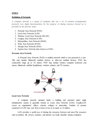
  • 1. UNIT I Definition of Network: A computer network is a group of computers that use a set of common communication protocols over digital interconnections for the purpose of sharing resources located on or provided by the network nodes 1. Personal Area Network (PAN) 2. Local Area Network (LAN) 3. Wireless Local Area Network (WLAN) 4. Campus Area Network (CAN) 5. Metropolitan Area Network (MAN) 6. Wide Area Network (WAN) 7. Storage-Area Network (SAN) 8. System-Area Network (also known as SAN) Personal Area Network A Personal Area Network (PAN) is smallest network which is very personal to a user. This may include Bluetooth enabled devices or infra-red enabled devices. PAN has connectivity range up to 10 meters. PAN may include wireless computer keyboard and mouse, Bluetooth enabled headphones, wireless printers and TV remotes. Local Area Network A computer network spanned inside a building and operated under single administrative system is generally termed as Local Area Network (LAN). Usually,LAN covers an organization’ offices, schools, colleges or universities. Number of systems connected in LAN may vary from as least as two to as much as 16 million. LAN provides a useful way of sharing the resources between end users.The resources such as printers, file servers, scanners, and internet are easily sharable among computers.
  • 2. Metropolitan Area Network The Metropolitan Area Network (MAN) generally expands throughout a city such as cable TV network. It can be in the form of Ethernet,Token-ring, ATM, or Fiber Distributed Data Interface (FDDI). Metro Ethernet is a service which is provided by ISPs. This service enables its users to expand their Local Area Networks. For example, MAN can help an organization to connect all of its offices in a city. Wide Area Network Wide Area Network (WAN) covers a wide area which may span across provinces and even a whole country. Generally, telecommunication networks are Wide Area Network. These networks provide connectivity to MANs and LANs. Since they are equipped with very high speed backbone, WANs use very expensive network equipment.
  • 3. Campus Area Network A campus network, campus area network, corporate area network or CAN is a computer network made up of an interconnection of local area networks within a limited geographical area A storage area network (SAN) It is a dedicated high-speed network or subnetwork that interconnects and presents shared pools of storage devices to multiple servers. A SAN moves storage resources off the common user network and reorganizes them into an independent, high-performance network. A wireless local area network (WLAN) It is a wireless distribution method for two or more devices that use high-frequency radio waves and often include an access point to the Internet. A WLAN allows users to move
  • 4. around the coverage area, often a home or small office, while maintaining a network connection system area network (SAN) It is a high-performance, connection-oriented network that can link a cluster of computers. A SAN delivers high bandwidth (1 Gbps or greater) with low latency. A SAN is typically switched by hubs that support eight or more nodes. TOPOLOGY The arrangements of nodes or systems called Topology. Topology can be classified in to five categories  Bus Topology  Star Topology  Ring Topology  Mesh Topoogy  Tree Topology BUS Topology Bus topology is a network type in which every computer and network device is connected to single cable. When it has exactly two endpoints, then it is called Linear Bus topology.
  • 5. Features of Bus Topology  It transmits data only in one direction.  Every device is connected to a single cable Advantages of Bus Topology  It is cost effective.  Cable required is least compared to other network topology.  Used in small networks.  It is easy to understand.  Easy to expand joining two cables together. Disadvantages of Bus Topology  Cables fails then whole network fails.  If network traffic is heavy or nodes are more the performance of the network decreases.  Cable has a limited length.  It is slower than the ring topology. RING Topology It is called ring topology because it forms a ring as each computer is connected to another computer, with the last one connected to the first. Exactly two neighbours for each device.
  • 6. Features of Ring Topology  A number of repeaters are used for Ring topology with large number of nodes, because if someone wants to send some data to the last node in the ring topology with 100 nodes, then the data will have to pass through 99 nodes to reach the 100th node. Hence to prevent data loss repeaters are used in the network.  The transmission is unidirectional, but it can be made bidirectional by having 2 connections between each Network Node, it is called Dual Ring Topology.  In Dual Ring Topology, two ring networks are formed, and data flow is in opposite direction in them. Also, if one ring fails, the second ring can act as a backup, to keep the network up.  Data is transferred in a sequential manner that is bit by bit. Data transmitted, has to pass through each node of the network, till the destination node. Advantages of Ring Topology  Transmitting network is not affected by high traffic or by adding more nodes, as only the nodes having tokens can transmit data.  Cheap to install and expand Disadvantages of Ring Topology  Troubleshooting is difficult in ring topology.  Adding or deleting the computers disturbs the network activity.  Failure of one computer disturbs the whole network. STAR Topology In this type of topology all the computers are connected to a single hub through a cable. This hub is the central node and all others nodes are connected to the central node.
  • 7. Features of Star Topology Every node has its own dedicated connection to the hub.  Hub acts as a repeater for data flow.  Can be used with twisted pair, Optical Fibre or coaxial cable. Advantages of Star Topology  Fast performance with few nodes and low network traffic.  Hub can be upgraded easily.  Easy to troubleshoot.  Easy to setup and modify.  Only that node is affected which has failed, rest of the nodes can work smoothly. Disadvantages of Star Topology  Cost of installation is high.  Expensive to use.  If the hub fails then the whole network is stopped because all the nodes depend on the hub.  Performance is based on the hub that is it depends on its capacity MESH Topology It is a point-to-point connection to other nodes or devices. All the network nodes are connected to each other. Mesh has n(n-1)/2 physical channels to link n devices. There are two techniques to transmit data over the Mesh topology, they are :  Routing  Flooding MESH Topology: Routing In routing, the nodes have a routing logic, as per the network requirements. Like routing logic to direct the data to reach the destination using the shortest distance. Or, routing logic which
  • 8. has information about the broken links, and it avoids those node etc. We can even have routing logic, to re-configure the failed nodes. MESH Topology: Flooding In flooding, the same data is transmitted to all the network nodes, hence no routing logic is required. The network is robust, and the its very unlikely to lose the data. But it leads to unwanted load over the network. Types of Mesh Topology Partial Mesh Topology : In this topology some of the systems are connected in the same fashion as mesh topology but some devices are only connected to two or three devices. Full Mesh Topology : Each and every nodes or devices are connected to each other. Features of Mesh Topology  Fully connected.  Robust.  Not flexible. Advantages of Mesh Topology  Each connection can carry its own data load.  It is robust.  Fault is diagnosed easily.  Provides security and privacy. Disadvantages of Mesh Topology  Installation and configuration is difficult.
  • 9.  Cabling cost is more.  Bulk wiring is required. TREE Topology It has a root node and all other nodes are connected to it forming a hierarchy. It is also called hierarchical topology. It should at least have three levels to the hierarchy. Features of Tree Topology  Ideal if workstations are located in groups.  Used in Wide Area Network. Advantages of Tree Topology  Extension of bus and star topologies.  Expansion of nodes is possible and easy.  Easily managed and maintained.  Error detection is easily done. Disadvantages of Tree Topology  Heavily cabled.  Costly.  If more nodes are added maintenance is difficult.  Central hub fails, network fails. HYBRID Topology It is two different types of topologies which is a mixture of two or more topologies. For example if in an office in one department ring topology is used and in another star topology is used, connecting these topologies will result in Hybrid Topology (ring topology and star topology).
  • 10. Features of Hybrid Topology  It is a combination of two or topologies  Inherits the advantages and disadvantages of the topologies included Advantages of Hybrid Topology  Reliable as Error detecting and trouble shooting is easy.  Effective.  Scalable as size can be increased easily.  Flexible. Disadvantages of Hybrid Topology  Complex in design.  Costly. Layers of OSI Model OSI stands for Open Systems Interconnection. It has been developed by ISO – ‘International Organization of Standardization‘, in the year 1984. It is a 7 layer architecture with each layer having specific functionality to perform. All these 7 layers work collaboratively to transmit the data from one person to another across the globe.
  • 11. 1. Physical Layer (Layer 1) : The lowest layer of the OSI reference model is the physical layer. It is responsible for the actual physical connection between the devices. The physical layer contains information in the form of bits. It is responsible for transmitting individual bits from one node to the next. When receiving data, this layer will get the signal received and convert it into 0s and 1s and send them to the Data Link layer, which will put the frame back together. The functions of the physical layer are : Bit synchronization: The physical layer provides the synchronization of the bits by providing a clock. This clock controls both sender and receiver thus providing synchronization at bit level. Bit rate control: The Physical layer also defines the transmission rate i.e. the number of bits sent per second. Physical topologies: Physical layer specifies the way in which the different, devices/nodes are arranged in a network i.e. bus, star or mesh topolgy. Transmission mode: Physical layer also defines the way in which the data flows between the two connected devices. The various transmission modes possible are: Simplex, half-duplex and full-duplex.
  • 12. * Hub, Repeater, Modem, Cables are Physical Layer devices. ** Network Layer, Data Link Layer and Physical Layer are also known as Lower Layers or Hardware Layers. Functions of Physical Layer Following are the various functions performed by the Physical layer of the OSI model. Representation of Bits: Data in this layer consists of stream of bits. The bits must be encoded into signals for transmission. It defines the type of encoding i.e. how 0's and 1's are changed to signal. Data Rate: This layer defines the rate of transmission which is the number of bits per second. Synchronization: It deals with the synchronization of the transmitter and receiver. The sender and receiver are synchronized at bit level. Interface: The physical layer defines the transmission interface between devices and transmission medium. Line Configuration: This layer connects devices with the medium: Point to Point configuration and Multipoint configuration. Topologies: Devices must be connected using the following topologies: Mesh, Star, Ring and Bus. Transmission Modes: Physical Layer defines the direction of transmission between two devices: Simplex, Half Duplex, Full Duplex. Deals with baseband and broadband transmission.
  • 13. 2. Data Link Layer (DLL) (Layer 2) : The data link layer is responsible for the node to node delivery of the message. The main function of this layer is to make sure data transfer is error-free from one node to another, over the physical layer. When a packet arrives in a network, it is the responsibility of DLL to transmit it to the Host using its MAC address. Data Link Layer is divided into two sub layers :  Logical Link Control (LLC)  Media Access Control (MAC)
  • 14. The packet received from Network layer is further divided into frames depending on the frame size of NIC(Network Interface Card). DLL also encapsulates Sender and Receiver’s MAC address in the header. The Receiver’s MAC address is obtained by placing an ARP(Address Resolution Protocol) request onto the wire asking “Who has that IP address?” and the destination host will reply with its MAC address. The functions of the data Link layer are : Framing: Framing is a function of the data link layer. It provides a way for a sender to transmit a set of bits that are meaningful to the receiver. This can be accomplished by attaching special bit patterns to the beginning and end of the frame. Physical addressing: After creating frames, Data link layer adds physical addresses (MAC address) of sender and/or receiver in the header of each frame. Error control: Data link layer provides the mechanism of error control in which it detects and retransmits damaged or lost frames. Flow Control: The data rate must be constant on both sides else the data may get corrupted thus , flow control coordinates that amount of data that can be sent before receiving acknowledgement. Access control: When a single communication channel is shared by multiple devices, MAC sub-layer of data link layer helps to determine which device has control over the channel at a given time. Types of framing – There are two types of framing: 1. Fixed size – The frame is of fixed size and there is no need to provide boundaries to the frame, length of the frame itself acts as delimiter. Drawback: It suffers from internal fragmentation if data size is less than frame size Solution: Padding 2. Variable size – In this there is need to define end of frame as well as beginning of next frame to distinguish. This can be done in two ways:
  • 15. Length field –introduce a length field in the frame to indicate the length of the frame. Used in Ethernet(802.3). The problem with this is that sometimes the length field might get corrupted. End Delimeter (ED) –introduce an ED(pattern) to indicate the end of the frame. Used in Token Ring. The problem with this is that ED can occur in the data. This can be solved by: 3. Network Layer (Layer 3) : Network layer works for the transmission of data from one host to the other located in different networks. It also takes care of packet routing i.e. selection of the shortest path to transmit the packet, from the number of routes available. The sender & receiver’s IP address are placed in the header by the network layer. The functions of the Network layer are : Routing: The network layer protocols determine which route is suitable from source to destination. This function of network layer is known as routing. Logical Addressing: In order to identify each device on internetwork uniquely, network layer defines an addressing scheme. The sender & receiver’s IP address are placed in the header by network layer. Such an address distinguishes each device uniquely and universally. * Segment in Network layer is referred as Packet. Network Layer Features With its standard functionalities, Layer 3 can provide various features as:  Quality of service management  Load balancing and link management  Security  Interrelation of different protocols and subnets with different schema.  Different logical network design over the physical network design. 4. Transport Layer (Layer 4) : Transport layer provides services to application layer and takes services from network layer. The data in the transport layer is referred to as Segments. It is responsible for the End to End Delivery of the complete message. The transport layer also provides the acknowledgement of the successful data transmission and re-transmits the data if an error is found. • At sender’s side:  Transport layer receives the formatted data from the upper layers, performs Segmentation and also implements Flow & Error control to ensure proper data transmission.  It also adds Source and Destination port number in its header and forwards the segmented data to the Network Layer.
  • 16. Note: The sender need to know the port number associated with the receiver’s application.  Generally, this destination port number is configured, either by default or manually. For example, when a web application makes a request to a web server, it typically uses port number 80, because this is the default port assigned to web applications. Many applications have default port assigned.  • At receiver’s side:  Transport Layer reads the port number from its header and forwards the Data which it has received to the respective application. It also performs sequencing and reassembling of the segmented data.  The functions of the transport layer are : Segmentation and Reassembly: This layer accepts the message from the (session) layer , breaks the message into smaller units . Each of the segment produced has a header associated with it. The transport layer at the destination station reassembles the message. Service Point Addressing: In order to deliver the message to correct process, transport layer header includes a type of address called service point address or port address. Thus by specifying this address, transport layer makes sure that the message is delivered to the correct process. The services provided by the transport layer : Connection Oriented Service: It is a three-phase process which include  Connection Establishment  Data Transfer  Termination / disconnection
  • 17. In this type of transmission, the receiving device sends an acknowledgement, back to the source after a packet or group of packet is received. This type of transmission is reliable and secure. Connection less service: It is a one-phase process and includes Data Transfer. In this type of transmission, the receiver does not acknowledge receipt of a packet. This approach allows for much faster communication between devices. Connection-oriented service is more reliable than connectionless Service. * Data in the Transport Layer Transport layer is operated by the Operating System. It is a part of the OS and communicates with the Application Layer by making system calls. Transport Layer is called as Heart of OSI model.is called as Segments. 5. Session Layer (Layer 5) : This layer is responsible for establishment of connection, maintenance of sessions, authentication and also ensures security. The functions of the session layer are : Session establishment, maintenance and termination: The layer allows the two processes to establish, use and terminate a connection. Synchronization : This layer allows a process to add checkpoints which are considered as synchronization points into the data. These synchronization point help to identify the error so that the data is re-synchronized properly, and ends of the messages are not cut prematurely and data loss is avoided. Dialog Controller : The session layer allows two systems to start communication with each other in half-duplex or full-duplex. **All the below 3 layers(including Session Layer) are integrated as a single layer in the TCP/IP model as “Application Layer”. **Implementation of these 3 layers is done by the network application itself. These are also known as Upper Layers or Software Layers.
  • 18. 6. Presentation Layer (Layer 6) : Presentation layer is also called the Translation layer.The data from the application layer is extracted here and manipulated as per the required format to transmit over the network. The functions of the presentation layer are : Translation : For example, ASCII to EBCDIC. Encryption/ Decryption : Data encryption translates the data into another form or code. The encrypted data is known as the cipher text and the decrypted data is known as plain text. A key value is used for encrypting as well as decrypting data. Compression: Reduces the number of bits that need to be transmitted on the network. 7. Application Layer (Layer 7) : At the very top of the OSI Reference Model stack of layers, we find Application layer which is implemented by the network applications. These applications produce the data, which has
  • 19. to be transferred over the network. This layer also serves as a window for the application services to access the network and for displaying the received information to the user. Ex: Application – Browsers, Skype Messenger etc. **Application Layer is also called as Desktop Layer. The functions of the Application layer are :  Network Virtual Terminal  FTAM-File transfer access and management  Mail Services  Directory Services OSI model acts as a reference model and is not implemented in the Internet because of its late invention. Current model being used is the TCP/IP model. I NETWORK LAYER The Network Layer is the third layer of the OSI model. It handles the service requests from the transport layer and further forwards the service request to the data link layer. The network layer translates the logical addresses into physical addresses.
  • 20. Functions of Network Layer Devices which work on Network Layer mainly focus on routing. Routing may include various tasks aimed to achieve a single goal. These can be:  Addressing devices and networks.  Populating routing tables or static routes.  Queuing incoming and outgoing data and then forwarding them according to quality of service constraints set for those packets.  Internetworking between two different subnets.  Delivering packets to destination with best efforts.  Provides connection oriented and connection less mechanism. Network Layer Features With its standard functionalities, Layer 3 can provide various features as:  Quality of service management  Load balancing and link management  Security  Interrelation of different protocols and subnets with different schema.  Different logical network design over the physical network design.  L3 VPN and tunnels can be used to provide end to end dedicated connectivity. 1.1ROUTING ALGORITHMS: Types of Routing Routing is a process which is performed by layer 3 (or network layer) devices in order to deliver the packet by choosing an optimal path from one network to another.
  • 21. There are 3 types of routing: 1. Static Routing 2. Default Routing 3. Dynamic Routing 1. Static routing Static routing is a process in which we have to manually add routes in routing table. Advantages  No routing overhead for router CPU which means a cheaper router can be used to do routing.  It adds security because only administrator can allow routing to particular networks only.  No bandwidth usage between routers. Disadvantage  For a large network, it is a hectic task for administrator to manually add each route for the network in the routing table on each router.  The administrator should have good knowledge of the topology. If a new administrator comes, then he has to manually add each route so he should have very good knowledge of the routes of the topology. 2. Default Routing  This is the method where the router is configured to send all packets towards a single router (next hop).  It doesn’t matter to which network the packet belongs, it is forwarded out to router which is configured for default routing.  It is generally used with stub routers. A stub router is a router which has only one route to reach all other networks. 3. Dynamic Routing – Dynamic routing makes automatic adjustment of the routes according to the current state of the route in the routing table. Dynamic routing uses protocols to discover network destinations and the routes to reach it. RIP and OSPF are the best examples of dynamic
  • 22. routing protocol. Automatic adjustment will be made to reach the network destination if one route goes down. 3.Dynamic Protocol A dynamic protocol have following features:  The routers should have the same dynamic protocol running in order to exchange routes.  When a router finds a change in the topology then router advertises it to all other routers. Advantages  Easy to configure.  More effective at selecting the best route to a destination remote network and also for discovering remote network. Disadvantage  Consumes more bandwidth for communicating with other neighbors.  Less secure than static routing. Routing Protocols: The Protocols are RIP Routing Information Protocol OSPFOpen Shortest Path BGPBorder Gateway Protocol RIP:
  • 23. III CONGESTION CONTROL ALGORITHMS: What is congestion? A state occurring in network layer when the message traffic is so heavy that it slows down network response time. Effects of Congestion  As delay increases, performance decreases.  If delay increases, retransmission occurs, making situation worse.  Congestion control algorithms Congestion Control Technique:
  • 24. Open Loop Congestion Control- Open loop congestion control policies are applied to prevent congestion before it happens. The congestion control is handled either by the source or the destination. Closed Loop Congestion Control- Closed-loop congestion control mechanisms try to alleviate congestion after it happens. Several mechanisms have been used by different protocols. Leaky Bucket Algorithm Let us consider an example to understand
  • 25. Imagine a bucket with a small hole in the bottom.No matter at what rate water enters the bucket, the outflow is at constant rate.When the bucket is full with water additional water entering spills over the sides and is lost. Figure(A) Leaky Bucket Similarly, each network interface contains a leaky bucket and the following steps are involved in  leaky bucket algorithm: When host wants to send packet, packet is thrown into the bucket. The bucket leaks at a constant rate, meaning the network interface transmits packets at a constant rate. Bursty traffic is converted to a uniform traffic by the leaky bucket. In practice the bucket is a finite queue that outputs at a finite rate.  Token bucket Algorithm Need of token bucket Algorithm:- The leaky bucket algorithm enforces output pattern at the average rate, no matter how bursty the traffic is. So in order to deal with the bursty traffic we need a flexible algorithm so that the data is not lost. One such algorithm is token bucket algorithm.  Steps of this algorithm can be described as follows:  In regular intervals tokens are thrown into the bucket. ƒ  The bucket has a maximum capacity. ƒ  If there is a ready packet, a token is removed from the bucket, and the packet is sent.  If there is no token in the bucket, the packet cannot be sent.  Ways in which token bucket is superior to leaky bucket: The leaky bucket algorithm controls the rate at which the packets are introduced in the network, but it is very conservative in nature. Some flexibility is introduced in the token
  • 26. bucket algorithm. In the token bucket, algorithm tokens are generated at each tick (up to a certain limit). For an incoming packet to be transmitted, it must capture a token and the transmission takes place at the same rate. Hence some of the busty packets are transmitted at the same rate if tokens are available and thus introduces some amount of flexibility in the system. Formula: M * s = C + ρ * s where S – is time taken M – Maximum output rate ρ – Token arrival rate C – Capacity of the token bucket in byte Figure(b) Let’s understand with an example, In figure (A) we see a bucket holding three tokens, with five packets waiting to be transmitted. For a packet to be transmitted, it must capture and destroy one token. In figure (B) We see that three of the five packets have gotten through, but the other two are stuck waiting for more tokens to be generated. Transmission Control Protocol (TCP)
  • 27. TCP is a connection oriented protocol and offers end-to-end packet delivery. It acts as back bone for connection.It exhibits the following key features:  Transmission Control Protocol (TCP) corresponds to the Transport Layer of OSI Model.  TCP is a reliable and connection oriented protocol. TCP offers:  Stream Data Transfer.  Reliability.  Efficient Flow Control  Full-duplex operation.  Multiplexing.  TCP offers connection oriented end-to-end packet delivery.  TCP ensures reliability by sequencing bytes with a forwarding acknowledgement number that indicates to the destination the next byte the source expect to receive.  It retransmits the bytes not acknowledged with in specified time period. TCP Services  TCP offers following services to the processes at the application layer:  Stream Delivery Service  Sending and Receiving Buffers  Bytes and Segments  Full Duplex Service  Connection Oriented Service  Reliable Service Stream Deliver Service TCP protocol is stream oriented because it allows the sending process to send data as stream of bytes and the receiving process to obtain data as stream of bytes. Sending and Receiving Buffers It may not be possible for sending and receiving process to produce and obtain data at same speed, therefore, TCP needs buffers for storage at sending and receiving ends. Bytes and Segments The Transmission Control Protocol (TCP), at transport layer groups the bytes into a packet. This packet is called segment. Before transmission of these packets, these segments are encapsulated into an IP datagram. Full Duplex Service
  • 28. Transmitting the data in duplex mode means flow of data in both the directions at the same time. Connection Oriented Service TCP offers connection oriented service in the following manner:  TCP of process-1 informs TCP of process – 2 and gets its approval.  TCP of process – 1 and TCP of process – 2 and exchange data in both the two directions.  After completing the data exchange, when buffers on both sides are empty, the two TCP’s destroy their buffers. Reliable Service For sake of reliability, TCP uses acknowledgement mechanism. Features of Transport Layer  The protocol layer just above the Internet Layer is the Host-to-Host Transport Layer.  This name is usually shortened to Transport Layer. The two most important protocols in the  Transport Layer are Transmission Control Protocol (TCP) and User Datagram Protocol (UDP).  TCP provides reliable data delivery service with end-to-end error detection and correction. UDP provides low-overhead, connectionless datagram delivery service.  Both protocols deliver data between the Application Layer and the Internet Layer. Applications programmers can choose whichever service is more appropriate for their specific applications. User Datagram Protocol  The User Datagram Protocol gives application programs direct access to a datagram delivery service, like the delivery service that IP provides.  This allows applications to exchange messages over the network with a minimum of protocol overhead.  UDP is an unreliable, connectionless datagram protocol. As noted previously, "unreliable" merely means that there are no techniques in the protocol for verifying that the data reached the other end of the network correctly. UDP message format
  • 29. 1.6.2 Transmission Control Protocol Applications that require the transport protocol to provide reliable data delivery use TCP because it verifies that data is delivered across the network accurately and in the proper sequence. TCP is a reliable, connection-oriented, byte-stream protocol. Let's look at each of the terms - reliable, connection-oriented, and byte-stream - in more detail. TCP segment format  TCP is connection-oriented. It establishes a logical end-to-end connection between the two communicating hosts. Control information, called a handshake, is exchanged between the two endpoints to establish a dialogue before data is transmitted.  TCP indicates the control function of a segment by setting the appropriate bit in the Flags field in word 4 of the segment header.
  • 30.  The type of handshake used by TCP is called a three-way handshake because three segments are exchanged.  It shows the simplest form of the three-way handshake. Host A begins the connection by sending host B a segment with the "Synchronize sequence numbers" (SYN) bit set.  This segment tells host B that A wishes to set up a connection, and it tells B what sequence number host A will use as a starting number for its segments. (Sequence numbers are used to keep data in the proper order.)  Host B responds to A with a segment that has the "Acknowledgment" (ACK) and SYN bits set. B's segment acknowledges the receipt of A's segment, and informs A which Sequence Number host B will start with. Finally, host A sends a segment that acknowledges receipt of B's segment, and transfers the first actual data. Three-way handshake
  • 31.  The Acknowledgment Segment (ACK) performs two functions: positive acknowledgment and flow control.  The acknowledgment tells the sender how much data has been received, and how much more the receiver can accept.  The Acknowledgment Number is the sequence number of the next byte the receiver expects to receive.  The standard does not require an individual acknowledgment for every packet. The acknowledgment number is a positive acknowledgment of all bytes up to that number. UNIT V Application Layer Protocols (DNS, SMTP, POP, FTP, HTTP) Study Notes An application layer protocol defines how application processes (clients and servers), running on different end systems, pass messages to each other. In particular, an application layer protocol defines  The types of messages, e.g., request messages and response messages.  The syntax of the various message types, i.e., the fields in the message and how the fields are delineated.  The semantics of the fields, i.e., the meaning of the information that the field is supposed to contain Rules for determining when and how a process sends messages and responds to messages. 1 SMTP (Simple Mail Transfer Protocol):(E-Mail)  One of the most popular network service is electronic mail (e-mail).  The TCP/IP protocol that supports electronic mail on the Internet is called Simple Mail Transfer Protocol (SMTP).
  • 32.  SMTP transfers messages from senders' mail servers to the recipients' mail servers using TCP connections.  Users based on e-mail addresses.  MTP provides services for mail exchange between users on the same or different computers. Following the client/server model:  SMTP has two sides: a client side which executes on a sender's mail server, and server side which executes on recipient's mail server.  Both the client and server sides of SMTP run on every mail server.  When a mail server sends mail (to other mail servers), it acts as an SMTP client.  When a mail server receives mail (from other mail servers) it acts as an SMTP server. TELNET (Terminal Network):  TELNET is client-server application that allows a user to log onto remote machine and lets the user to access any application program on a remote computer.  TELNET uses the NVT (Network Virtual Terminal) system to encode characters on the local system.  On the server (remote) machine, NVT decodes the characters to a form acceptable to the remote machine.  TELNET is a protocol that provides a general, bi-directional, eight-bit byte oriented communications facility.  Many application protocols are built upon the TELNET protocol.  Telnet services are used on PORT 23.
  • 33. FTP (File Transfer Protocol):  FTP is the standard mechanism provided by TCP/IP for copying a file from one host to another.  FTP differs form other client-server applications because it establishes 2 connections between hosts.  Two connections are: Data Connection and Control Connection.  Data Connection uses PORT 20 for the purpose and control connection uses PORT 21 for the purpose.  FTP is built on a client-server architecture and uses separate control and data connections between the client and the server.  One connection is used for data transfer, the other for control information (commands and responses).  It transfer data reliably and efficiently. Multipurpose Internet Mail Extensions (MIME):  It is an extension of SMTP that allows the transfer of multimedia messages.  If binary data is included in a message MIME headers are used to inform the receiving mail agent: 1. Content-Transfer-Encoding: Header alerts the receiving user agent that the message body has been ASCII encoded and the type of encoding used. 2. Content-Type: Header informs the receiving mail agent about the type of data included in the message.
  • 34. POP (Post Office Protocol):  POP is also called as POP3 protocol.  This is a protocol used by a mail server in conjunction with SMTP to receive and holds mail for hosts.  POP3 mail server receives e-mails and filters them into the appropriate user folders. When a user connects to the mail server to retrieve his mail, the messages are downloaded from mail server to the user's hard disk. HTTP (Hypertext Transfer Protocol):  This is a protocol used mainly to access data on the World Wide Web (www).  The Hypertext Transfer Protocol (HTTP) the Web's main application-layer protocol although current browsers can access other types of servers.  A respository of information spread all over the world and linked together.  The HTIP protocol transfer data in the form of plain text, hyper text, audio, video and so on.  HTTP utilizes TCP connections to send client requests and server replies.  it is a synchronous protocol which works by making both persistent and non persistent connections.
  • 35. Domain Name System (DNS):  To identify an entity, TCP/IP protocol uses the IP address which uniquely identifies the connection of a host to the Internet.  DNS is a hierarchical system, based on a distributed database, that uses a hierarchy of Name Servers to resolve Internet host names into the corresponding IP addresses required for packet routing by issuing a DNS query to a name server. In TCP/IP, this is the domain name system.  DNS in the Internet: DNS is protocol that can be used in different platforms. Domain name space is divided into three categories.  Generic Domain: The generic domain defines registered hosts according, to their generic behaviour. Each node in the tree defines a domain which is an index to the domain name space database.  Country Domain: The country domain section follows the same format as the generic domain but uses 2 characters country abbreviations (e.g., US for United States) in place of 3 characters.  Inverse Domain: The inverse domain is used to map an address to a name.
  • 36. Domain Names Domain Name is a symbolic string associated with an IP address. There are several domain names available; some of them are generic such as com, edu, gov, net etc, while some country level domain names such as au, in, za, us etc. The following table shows the Generic Top-Level Domain names: The following table shows the Generic Top-Level Domain names: Domain Name Meaning Com Commercial business Edu Education Gov U.S. government agency Int International entity Mil U.S. military Net Networking organization Org Non profit organization
  • 37. Network Security: Network security consists of the policies and practices adopted to prevent and monitor unauthorized access, misuse, modification, or denial of a computer network and network- accessible resources. Types of Network Security Devices Active Devices These security devices block the surplus traffic. Firewalls, antivirus scanning devices, and content filtering devices are the examples of such devices. Passive Devices These devices identify and report on unwanted traffic, for example, intrusion detection appliances. Preventative Devices These devices scan the networks and identify potential security problems. For example, penetration testing devices and vulnerability assessment appliances. Unified Threat Management (UTM) These devices serve as all-in-one security devices. Examples include firewalls, content filtering, web caching, etc. Features of Network Security: Access Control: This is done through Network Access Control which ensures that only a handful of authorized personnel must be able to work with allowed amount of resources. Antivirus and Anti-malware Software: This type of network security ensures that any malicious software does not enter the network and jeopardize the security of the data. The malicious software like Viruses, Trojans, Worms are handled by the same.
  • 38. Cloud Security: This data must be protected an it should be ensured that this protection is not jeopardize over anything. Many businesses embrace SaaS applications for providing some of its employees the allowance of accessing the data stored over the cloud. This type of security ensures in creating gaps in visibility of the data. CRYPTOGRAPHY  Cryptography is the study and practice of techniques for secure communication in the presence of third parties called adversaries.  It deals with developing and analyzing protocols which prevents malicious third parties from retrieving information being shared between two entities thereby following the various aspects of information security.  Secure Communication refers to the scenario where the message or data shared between two parties can’t be accessed by an adversary.  In Cryptography, an Adversary is a malicious entity, which aims to retrieve precious information or data thereby undermining the principles of information security.  Data Confidentiality, Data Integrity, Authentication and Non-repudiation are core principles of modern-day cryptography.  Confidentiality refers to certain rules and guidelines usually executed under confidentiality agreements which ensure that the information is restricted to certain people or places.  Data integrity refers to maintaining and making sure that the data stays accurate and consistent over its entire life cycle.  Authentication is the process of making sure that the piece of data being claimed by the user belongs to it.  Non-repudiation refers to ability to make sure that a person or a party associated with a contract or a communication cannot deny the authenticity of their signature over their document or the sending of a message.
  • 39. Consider two parties Alice and Bob. Now, Alice wants to send a message m to Bob over a secure channel. So, what happens is as follows. The sender’s message or sometimes called the Plaintext, is converted into an unreadable form using a Key k. The resultant text obtained is called the Ciphertext. This process is known as Encryption. At the time of receival, the Ciphertext is converted back into the plaintext using the same Key k, so that it can be read by the receiver. This process is known as Decryption. Alice (Sender) Bob (Receiver) C = E (m, k) ----> m = D (C, k) Here, C refers to the Ciphertext while E and D are the Encryption and Decryption algorithms respectively.Let’s consider the case of Caesar Cipher or Shift Cipher as an example. As the name suggests, in Caesar Cipher each character in a word is replaced by another character under some defined rules. Thus, if A is replaced by D, B by E and so on. Then, each character in the word would be shifted by a position of 3. For example: Plaintext : Geeksforgeeks Ciphertext : Jhhnvirujhhnv Cryptography Techniques-
  • 40. Cryptography techniques may be classified as-  Symmetric Key Cryptography  Asymmetric Key Cryptography Symmetric Key Cryptography- In this technique,Both sender and receiver uses a common key to encrypt and decrypt the message. This secret key is known only to the sender and to the receiver. It is also called as secret key cryptography. Working- The message exchange using symmetric key cryptography involves the following steps-  Before starting the communication, sender and receiver shares the secret key.  This secret key is shared through some external means.  At sender side, sender encrypts the message using his copy of the key.  The cipher text is then sent to the receiver over the communication channel.  At receiver side, receiver decrypts the cipher text using his copy of the key.  After decryption, the message converts back into readable format. Symmetric Encryption Algorithms- Some of the encryption algorithms that use symmetric key are-  Advanced Encryption Standard (AES)  Data Encryption Standard (DES) Advantages- The advantages of symmetric key algorithms are-  They are efficient.  They take less time to encrypt and decrypt the message.
  • 41. UNIT III I DATALINK LAYER  Data Link Layer is second layer of OSI Layered Model. This layer is one of the most complicated layers and has complex functionalities and liabilities. Data link layer hides the details of underlying hardware and represents itself to upper layer as the medium to communicate.  Data link layer works between two hosts which are directly connected in some sense. This direct connection could be point to point or broadcast. Systems on broadcast network are said to be on same link. The work of data link layer tends to get more complex when it is dealing with multiple hosts on single collision domain.  Data link layer is responsible for converting data stream to signals bit by bit and to send that over the underlying hardware. At the receiving end, Data link
  • 42. layer picks up data from hardware which are in the form of electrical signals, assembles them in a recognizable frame format, and hands over to upper layer. Data link layer has two sub-layers: Logical Link Control: It deals with protocols, flow-control, and error control Media Access Control: It deals with actual control of media Functionality of Data-link Layer Data link layer does many tasks on behalf of upper layer. These are: Framing Data-link layer takes packets from Network Layer and encapsulates them into Frames.Then, it sends each frame bit-by-bit on the hardware. At receiver’ end, data link layer picks up signals from hardware and assembles them into frames. Addressing Data-link layer provides layer-2 hardware addressing mechanism. Hardware address is assumed to be unique on the link. It is encoded into hardware at the time of manufacturing. Synchronization When data frames are sent on the link, both machines must be synchronized in order to transfer to take place. Error Control Sometimes signals may have encountered problem in transition and the bits are flipped.These errors are detected and attempted to recover actual data bits. It also provides error reporting mechanism to the sender. Flow Control Stations on same link may have different speed or capacity. Data-link layer ensures flow control that enables both machine to exchange data on same speed. Multi-Access When host on the shared link tries to transfer the data, it has a high probability of collision. Data-link layer provides mechanism such as CSMA/CD to equip capability of accessing a shared media among multiple Systems. II Error Detection & Correction  There are many reasons such as noise, cross-talk etc.,  It may help data to get corrupted during transmission.  The upper layers work on some generalized view of network architecture and are not aware of actual hardware data processing.Hence,
  • 43.  The upper layers expect error-free transmission between the systems. Most of the applications would not function expectedly if they receive erroneous data.  Data-link layer uses some error control mechanism to ensure that frames (data bit streams) are transmitted with certain level of accuracy. But to understand how errors is controlled, it is essential to know what types of errors may occur. Types of Errors There may be three types of errors:  Single bit error  Multiple bits error  Burst error  Error Control Single bit error In a frame, there is only one bit, anywhere though, which is corrupt. Multiple bits error Frame is received with more than one bits in corrupted state. Burst error Frame contains more than1 consecutive bits corrupted. Error Control Error control mechanism may involve two possible ways: a. Error detection b. Error correction ERROR DETECTION: Errors in the received frames are detected by means of Parity Check and Cyclic Redundancy Check (CRC). In both cases, few extra bits are sent along with actual data to confirm that bits received at other end are same as they were sent. If the counter-check at receiver’ end fails, the bits are considered corrupted.
  • 44. (i) Parity Check  One extra bit is sent along with the original bits to make number of 1s either even in case of even parity, or odd in case of odd parity.  The sender while creating a frame counts the number of 1s in it. For example, if even parity is used and number of 1s is even then one bit with value 0 is added.  This way number of 1s remains even.If the number of 1s is odd, to make it even a bit with value 1 is added.  The receiver simply counts the number of 1s in a frame. If the count of 1s is even and even parity is used, the frame is considered to be not-corrupted and is accepted. If the count of 1s is odd and odd parity is used, the frame is still not corrupted.  If a single bit flips in transit, the receiver can detect it by counting the number of 1s. But when more than one bits are erro neous, then it is very hard for the receiver to detect the error. (ii) Cyclic Redundancy Code  The receiver simply counts the number of 1s in a frame.  If the count of 1s is even and even parity is used, the frame is considered to be not- corrupted and is accepted.  If the count of 1s is odd and odd parity is used, the frame is still not corrupted.If a single bit flips in transit, the receiver can detect it by counting the number of 1s.  But when more than one bits are erro neous, then it is very hard for the receiver to detect the error.
  • 45. Error Correction In the digital world, error correction can be done in two ways:  Backward Error Correction When the receiver detects an error in the data received, it requests back the sender to retransmit the data unit.  Forward Error Correction When the receiver detects some error in the data received, it executes error-correcting code, which helps it to auto-recover and to correct some kinds of errors. The first one, Backward Error Correction, is simple and can only be efficiently used where retransmitting is not expensive. For example, fiber optics. But in case of wireless transmission retransmitting may cost too much. In the latter case, Forward Error Correction is used. To correct the error in data frame, the receiver must know exactly which bit in the frame is corrupted. To locate the bit in error, redundant bits are used as parity bits for error detection.For example, we take ASCII words (7 bits data), then there could be 8 kind of information we need: first seven bits to tell us which bit is error and one more bit to tell that there is no error III ELEMENTARY DATA PROTOCOL Data link protocols can be broadly divided into two categories, depending on whether the transmission channel is noiseless or noisy.
  • 46. Simplex Protocol  The Simplex protocol is hypothetical protocol designed for unidirectional data transmission over an ideal channel, i.e. a channel through which transmission can never go wrong.  It has distinct procedures for sender and receiver.  The sender simply sends all its data available onto the channel as soon as they are available its buffer.  The receiver is assumed to process all incoming data instantly.  It is hypothetical since it does not handle flow control or error control. Stop – and – Wait Protocol  Stop – and – Wait protocol is for noiseless channel too. It provides unidirectional data transmission without any error control facilities.  However, it provides for flow control so that a fast sender does not drown a slow receiver. The receiver has a finite buffer size with finite processing speed.  The sender can send a frame only when it has received indication from the receiver that it is available for further data processing. Stop – and – Wait ARQ  Stop – and – wait Automatic Repeat Request (Stop – and – Wait ARQ) is a variation of the above protocol with added error control mechanisms, appropriate for noisy channels.  The sender keeps a copy of the sent frame. It then waits for a finite time to receive a positive acknowledgement from receiver.  If the timer expires or a negative acknowledgement is received, the frame is retransmitted. If a positive acknowledgement is received then the next frame is sent. Go – Back – N ARQ  Go – Back – N ARQ provides for sending multiple frames before receiving the acknowledgement for the first frame.  It uses the concept of sliding window, and so is also called sliding window protocol.
  • 47.  The frames are sequentially numbered and a finite number of frames are sent.  If the acknowledgement of a frame is not received within the time period, all frames starting from that frame are retransmitted. Selective Repeat ARQ  This protocol also provides for sending multiple frames before receiving the acknowledgement for the first frame.  However, here only the erroneous or lost frames are retransmitted, while the good frames are received and buffered. IV Common Data Link Protocols Synchronous Data Link Protocol (SDLC) –  SDLC was developed by IBM in the 1970s as part of Systems Network Architecture.  It was used to connect remote devices to mainframe computers.  It ascertained that data units arrive correctly and with right flow from one network point to the next. High Level Data Link Protocol (HDLC) –  HDLC is based upon SDLC and provides both unreliable service and reliable service.  It is a bit – oriented protocol that is applicable for both point – to – point and multipoint communications. Serial Line Interface Protocol (SLIP) –  This is a simple protocol for transmitting data units between an Internet service provider (ISP) and home user over a dial-up link.  It does not provide error detection / correction facilities. Point - to - Point Protocol (PPP) –
  • 48.  This is used to transmit multiprotocol data between two directly connected (point-to- point) computers.  It is a byte – oriented protocol that is widely used in broadband communications having heavy loads and high speeds. Link Control Protocol (LCP) –  It one of PPP protocols that is responsible for establishing, configuring, testing, maintaining and terminating links for transmission.  It also imparts negotiation for set up of options and use of features by the two endpoints of the links. Network Control Protocol (NCP) –  These protocols are used for negotiating the parameters and facilities for the network layer. For every higher-layer protocol supported by PPP, one NCP is there. IV Sliding Window Protocol 1. Sliding window protocols are data link layer protocols for reliable and sequential delivery of data frames. 2. The sliding window is also used in Transmission Control Protocol. 3. In this protocol, multiple frames can be sent by a sender at a time before receiving an acknowledgment from the receiver. 4. The term sliding window refers to the imaginary boxes to hold frames. Sliding window method is also known as windowing.
  • 49. Types of Sliding Window Protocols Go – Back – N ARQ  Go – Back – N ARQ provides for sending multiple frames before receiving the acknowledgment for the first frame.  It uses the concept of sliding window, and so is also called sliding window protocol. The frames are sequentially numbered and a finite number of frames are sent.  If the acknowledgment of a frame is not received within the time period, all frames starting from that frame are retransmitted.
  • 50. Selective Repeat ARQ  This protocol also provides for sending multiple frames before receiving the acknowledgment for the first frame.  However, here only the erroneous or lost frames are retransmitted, while the good frames are received and buffered. MAC Layer in the OSI Model The Open System Interconnections (OSI) model is a layered networking framework that conceptualizes how communications should be done between heterogeneous systems. The data link layer is the second lowest layer. It is divided into two sublayers −  The logical link control (LLC) sublayer  The medium access control (MAC) sublayer The following diagram depicts the position of the MAC layer – Functions of MAC Layer  It provides an abstraction of the physical layer to the LLC and upper layers of the OSI network.  It is responsible for encapsulating frames so that they are suitable for transmission via the physical medium.  It resolves the addressing of source station as well as the destination station, or groups of destination stations.  It performs multiple access resolutions when more than one data frame is to be transmitted. It determines the channel access methods for transmission.  It also performs collision resolution and initiating retransmission in case of collisions.  It generates the frame check sequences and thus contributes to protection against transmission errors.
  • 51. MAC Addresses  MAC address or media access control address is a unique identifier allotted to a network interface controller (NIC) of a device.  It is used as a network address for data transmission within a network segment like Ethernet, Wi-Fi, and Bluetooth.  MAC address is assigned to a network adapter at the time of manufacturing. It is hardwired or hard-coded in the network interface card (NIC).  A MAC address comprises of six groups of two hexadecimal digits, separated by hyphens, colons, or no separators. An example of a MAC address is 00:0A:89:5B:F0:11.