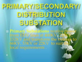
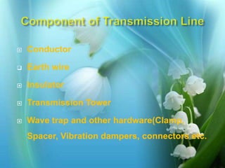
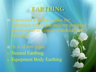
PRESENTAION
ON
GRID SUB-STATION
By Avdhesh kumar meena
B.Tech 4th Year Electrical Branch
NIET Alwar Rajasthan
avdheshkumarmeena10@gmail.com
 Generating Station
 Transmission Line
 Sub-Stations
 Classification based on voltage levels,
e.g. : A.C. Substation : EHV, HV, MV,
LV; HVDC Substation.
 Classification based on Outdoor or
Indoor : Outdoor substation is under
open sky. Indoor substation is inside a
building.
 Primary Substations receive power
from EHV lines at 400KV, 220KV,
132KV and transform the voltage to
66KV, 33KV or 22KV to suit the
local requirements .

 Secondary Substations receive
power at 66/33KV which is
stepped down usually to 11KV.
 Distribution Substations receive
power at 11KV, 6.6 KV and step
down to a volt suitable for LV
distribution purposes, normally
at 415 volts
ELECTRICAL
TRANSMISSION
LINE
Electrical transmission
system is the means of
transmitting power from
generating station to
different load centres.
 Conductor
 Earth wire
 Insulator
 Transmission Tower
 Wave trap and other hardware(Clamp,
Spacer, Vibration dampers, connectors etc.
 Used to reduce earth wire potential
and stress on insulators at the time
of stroke and also for safety
 Earth resistance depend upon soil
resistivity(general 100 Ω-m)
 It provides a surface under the
substation which has uniform potential
nearly equal to zero or Absolute Earth
Potential.
 It is of two types
o Neutral Earthing
o Equipment Body Earthing
EARTHING
 Earth wire provided above the
phase conductor across the line
and grounded at every tower.
Optical Ground Wire
Advantages :
Serves the dual purpose of
ground wire and
communication.
High speed data transmission.
Optical Ground Wire
 Major power station= 0.5 Ohm.
 Major Sub-stations= 1.0 Ohm
 Minor Sub-station = 2 Ohm
 Neutral Bushing. =2 Ohm
 Service connection = 4 Ohm
 Medium Voltage Network =2 Ohm
 L.T.Lightening Arrestor= 4 Ohm
 L.T.Pole= 5 Ohm
 H.T.Pole =10 Ohm
 Tower =20-30 Ohm
 Mechanical Requirement
 Electrical Requirement
 Mechanical Requirement
 Tensile Strength(For Tension)
 Strain Strength(For Vibration)
 Insulator are required to
support the line conductor and
provide clearance from ground
and structure.
 A Transformer is a static
device that transfers Electrical
energy from one Electrical
circuit to another Electrical
circuit by means of a common
Magnetic Circuit.
TRANSFORMER USED IN GSS
 POWER X-MER
 C.T.
 P.T.
 STATION X-MER
 To step-down the voltage and
transfer power from one A.C
voltage to another A.C Voltage at
same frequency
THANK YOU

Transmission network

  • 1.
    PRESENTAION ON GRID SUB-STATION By Avdheshkumar meena B.Tech 4th Year Electrical Branch NIET Alwar Rajasthan avdheshkumarmeena10@gmail.com
  • 3.
     Generating Station Transmission Line  Sub-Stations
  • 4.
     Classification basedon voltage levels, e.g. : A.C. Substation : EHV, HV, MV, LV; HVDC Substation.  Classification based on Outdoor or Indoor : Outdoor substation is under open sky. Indoor substation is inside a building.
  • 5.
     Primary Substationsreceive power from EHV lines at 400KV, 220KV, 132KV and transform the voltage to 66KV, 33KV or 22KV to suit the local requirements . 
  • 6.
     Secondary Substationsreceive power at 66/33KV which is stepped down usually to 11KV.  Distribution Substations receive power at 11KV, 6.6 KV and step down to a volt suitable for LV distribution purposes, normally at 415 volts
  • 8.
  • 9.
    Electrical transmission system isthe means of transmitting power from generating station to different load centres.
  • 11.
     Conductor  Earthwire  Insulator  Transmission Tower  Wave trap and other hardware(Clamp, Spacer, Vibration dampers, connectors etc.
  • 13.
     Used toreduce earth wire potential and stress on insulators at the time of stroke and also for safety  Earth resistance depend upon soil resistivity(general 100 Ω-m)
  • 14.
     It providesa surface under the substation which has uniform potential nearly equal to zero or Absolute Earth Potential.  It is of two types o Neutral Earthing o Equipment Body Earthing
  • 15.
  • 16.
     Earth wireprovided above the phase conductor across the line and grounded at every tower.
  • 17.
  • 18.
    Advantages : Serves thedual purpose of ground wire and communication. High speed data transmission. Optical Ground Wire
  • 20.
     Major powerstation= 0.5 Ohm.  Major Sub-stations= 1.0 Ohm  Minor Sub-station = 2 Ohm  Neutral Bushing. =2 Ohm  Service connection = 4 Ohm  Medium Voltage Network =2 Ohm  L.T.Lightening Arrestor= 4 Ohm  L.T.Pole= 5 Ohm  H.T.Pole =10 Ohm  Tower =20-30 Ohm
  • 23.
     Mechanical Requirement Electrical Requirement  Mechanical Requirement  Tensile Strength(For Tension)  Strain Strength(For Vibration)
  • 25.
     Insulator arerequired to support the line conductor and provide clearance from ground and structure.
  • 29.
     A Transformeris a static device that transfers Electrical energy from one Electrical circuit to another Electrical circuit by means of a common Magnetic Circuit.
  • 30.
    TRANSFORMER USED INGSS  POWER X-MER  C.T.  P.T.  STATION X-MER
  • 32.
     To step-downthe voltage and transfer power from one A.C voltage to another A.C Voltage at same frequency
  • 41.