This document provides an overview of electrification and architectural illumination. It discusses key concepts like:
1. The importance of building services like lighting, heating, ventilation and other systems that make buildings safe and comfortable.
2. Common materials used in electrification like conductors, insulators, and semiconductors.
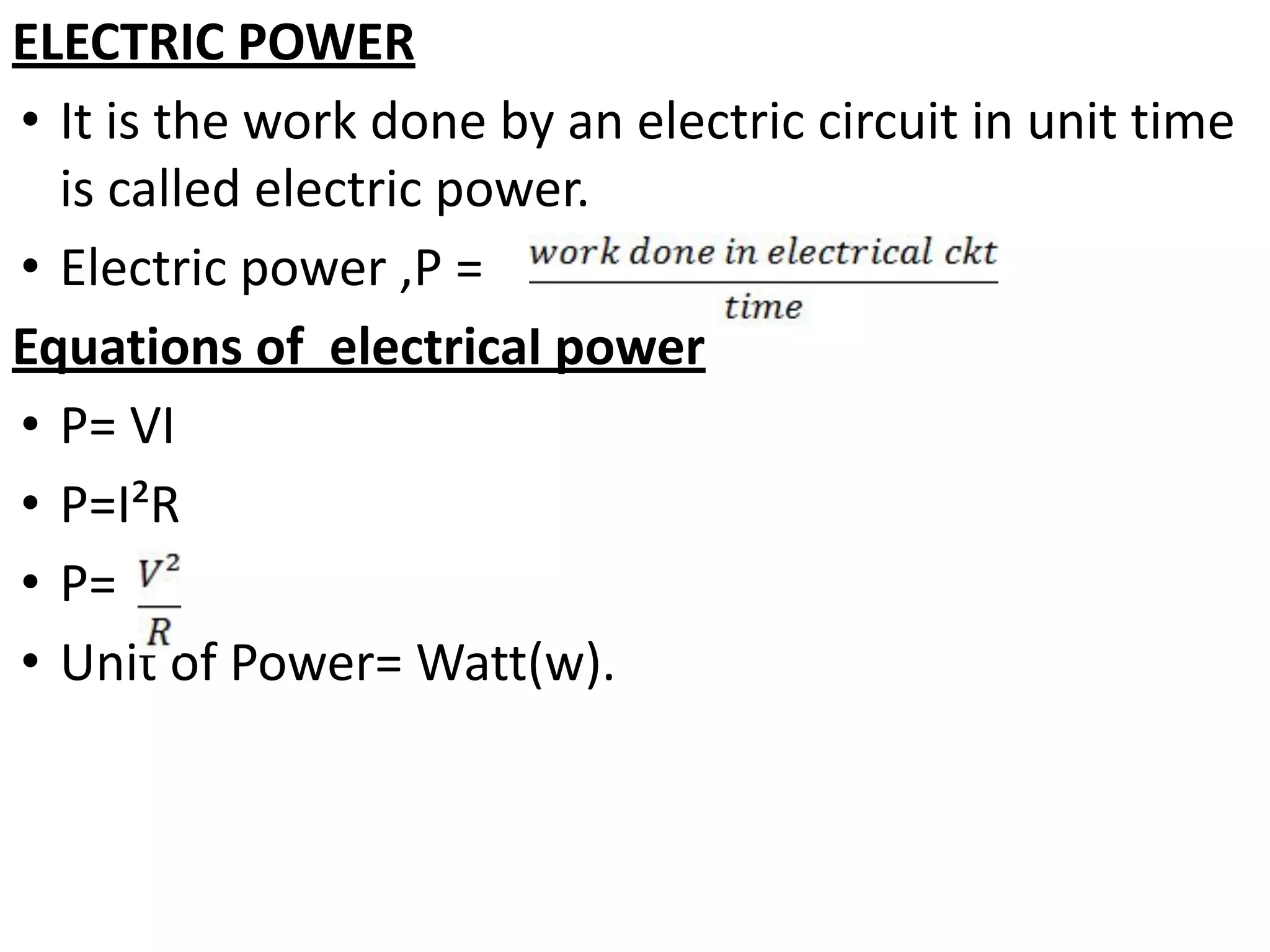
3. Key electrical terminology like current, voltage, resistance, and units of measurement.
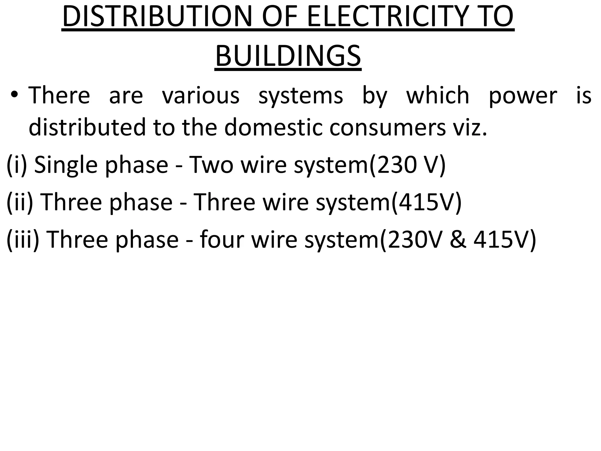
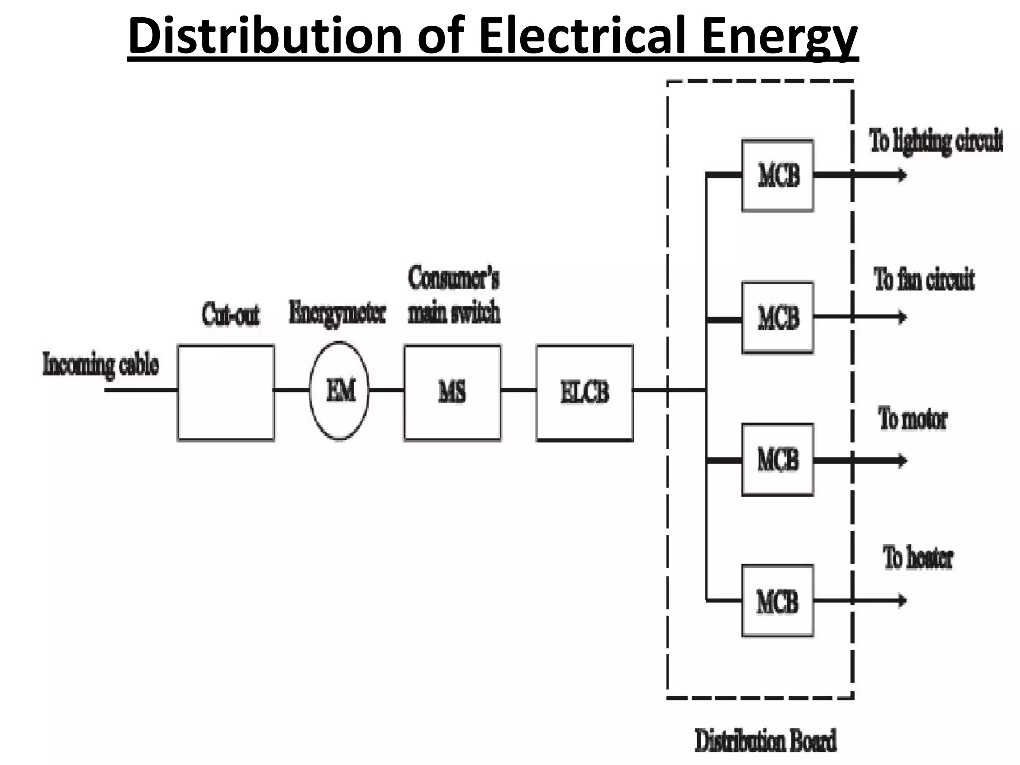
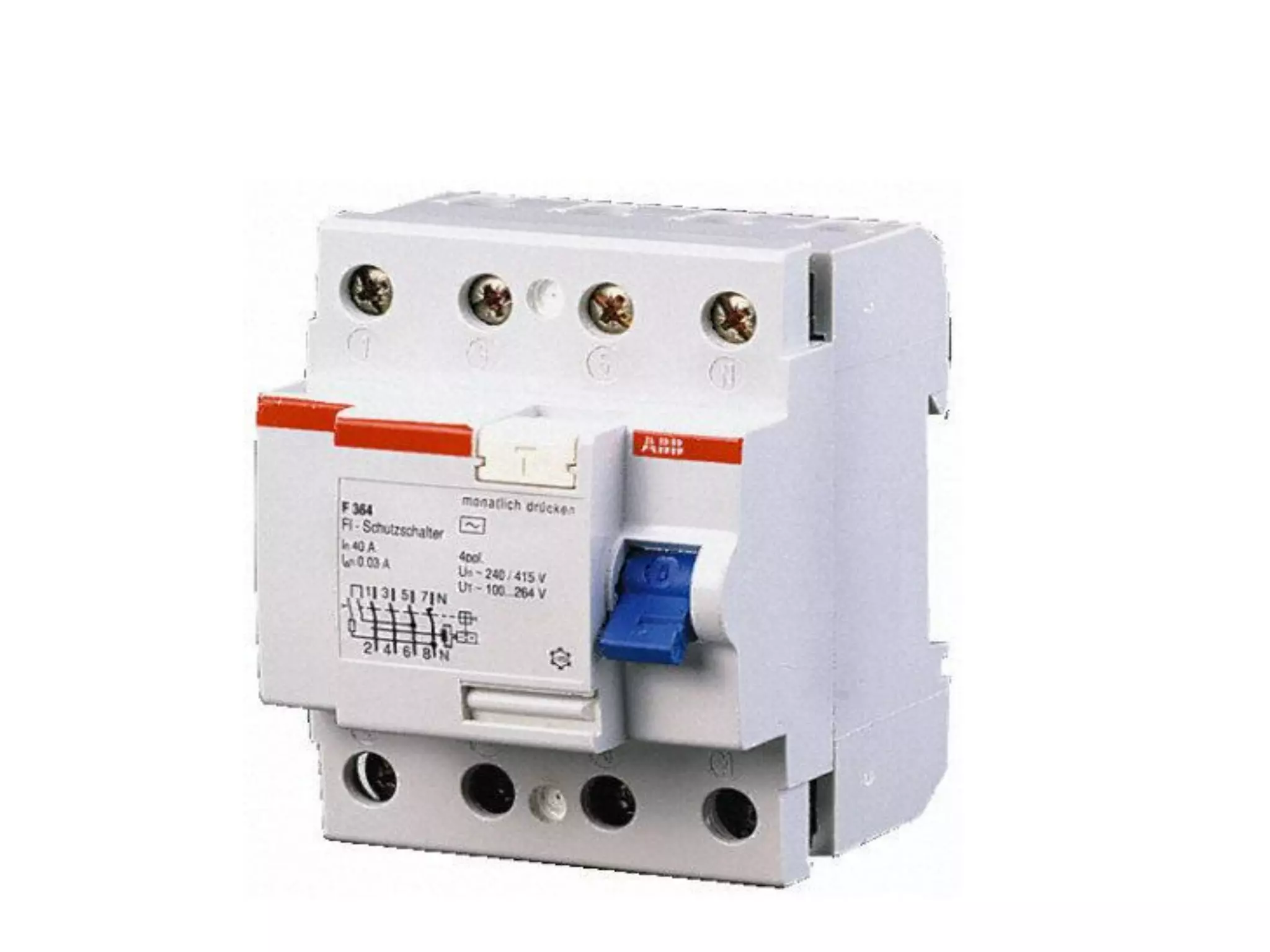
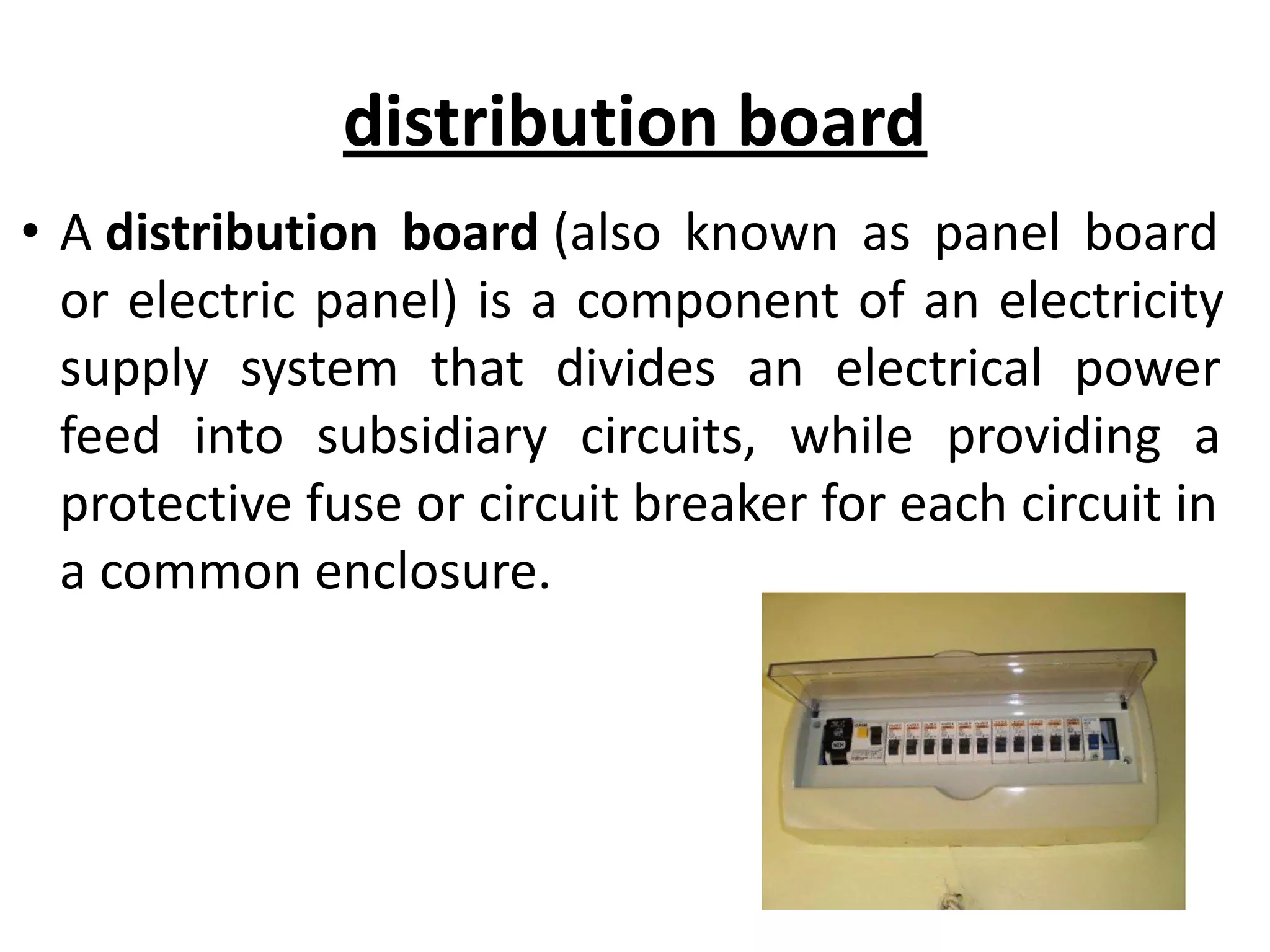
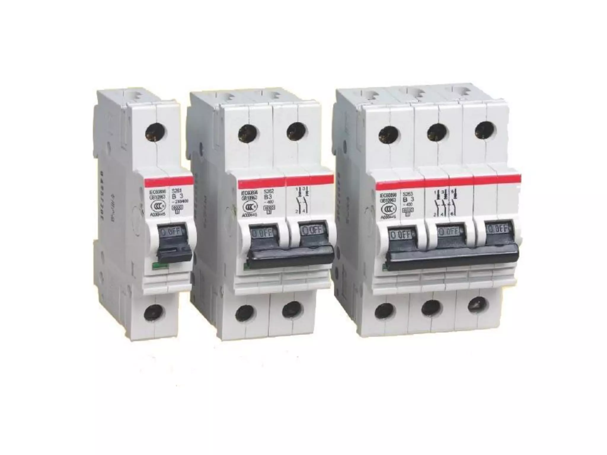
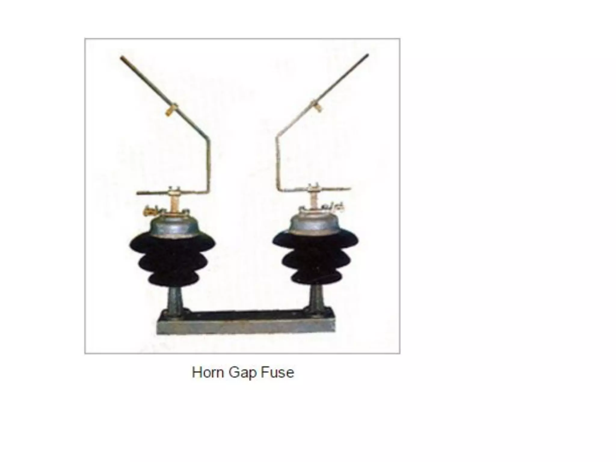
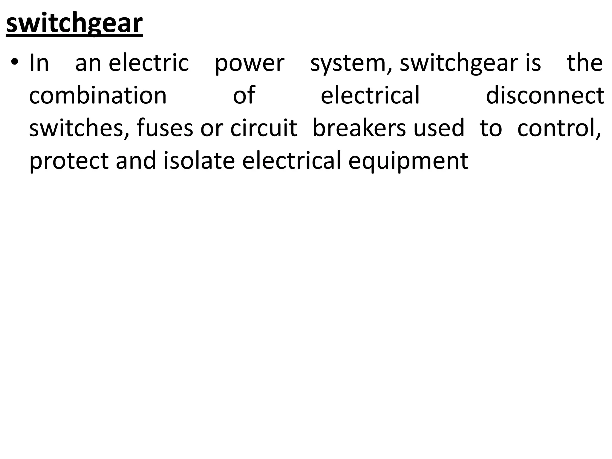
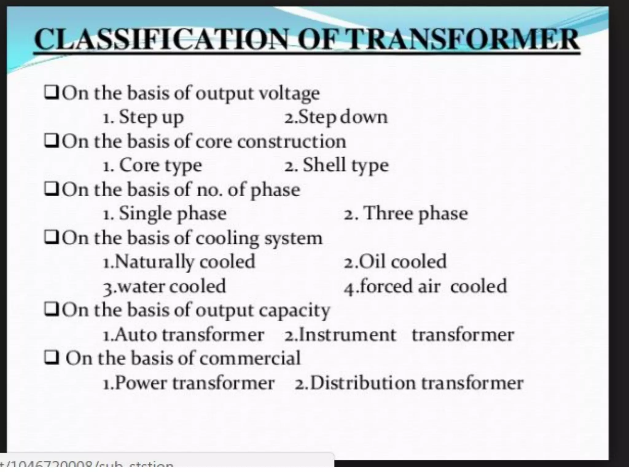
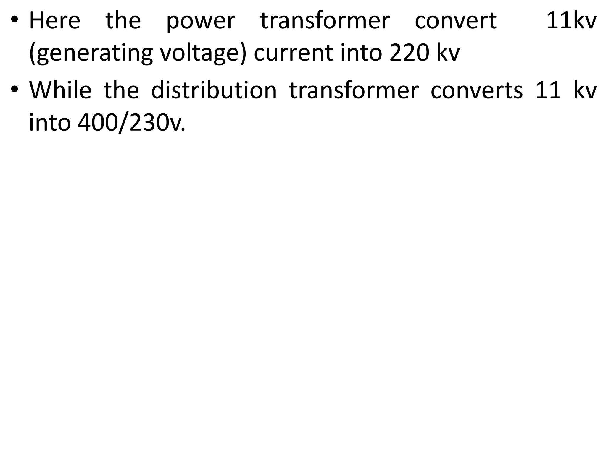
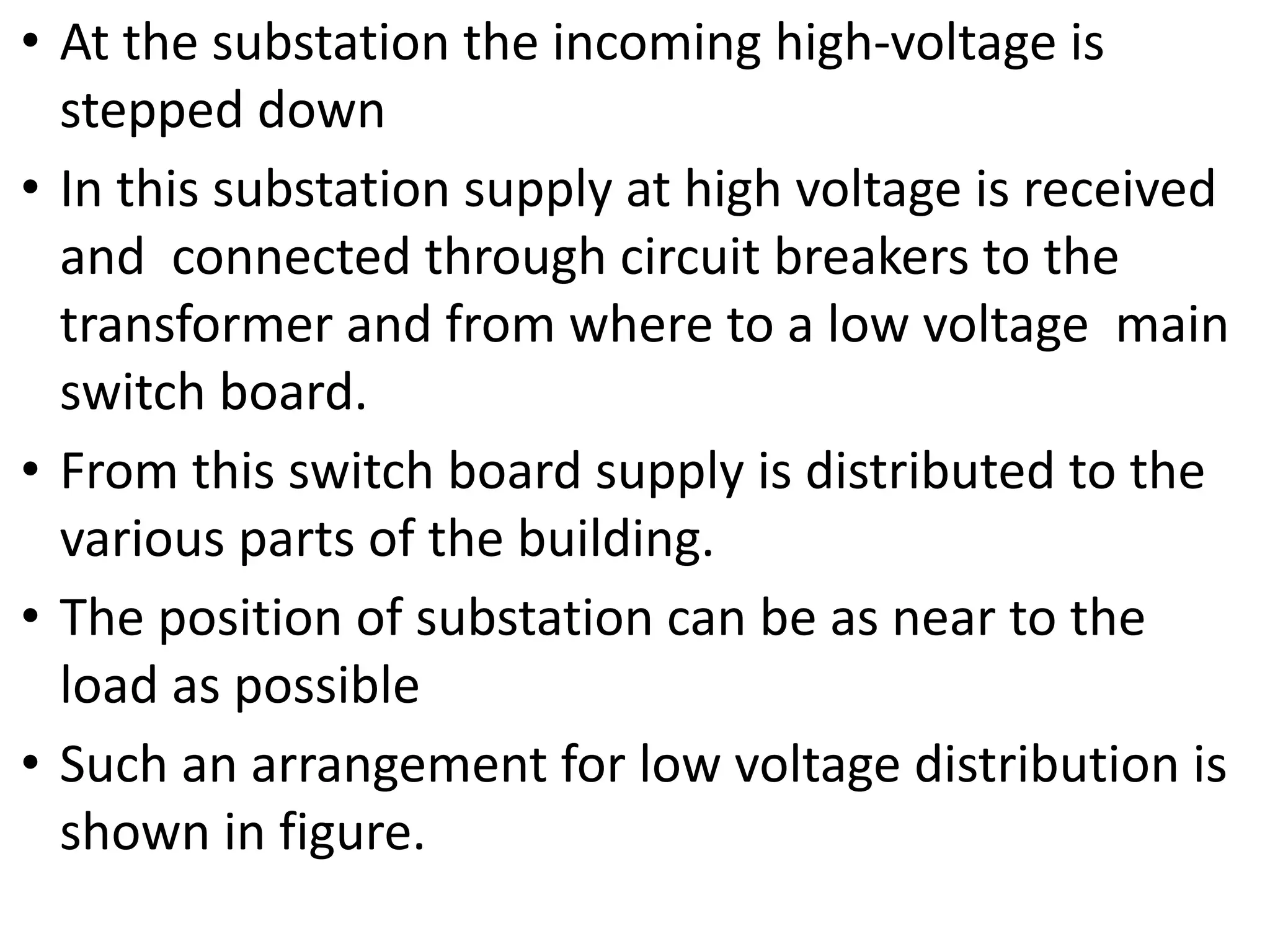
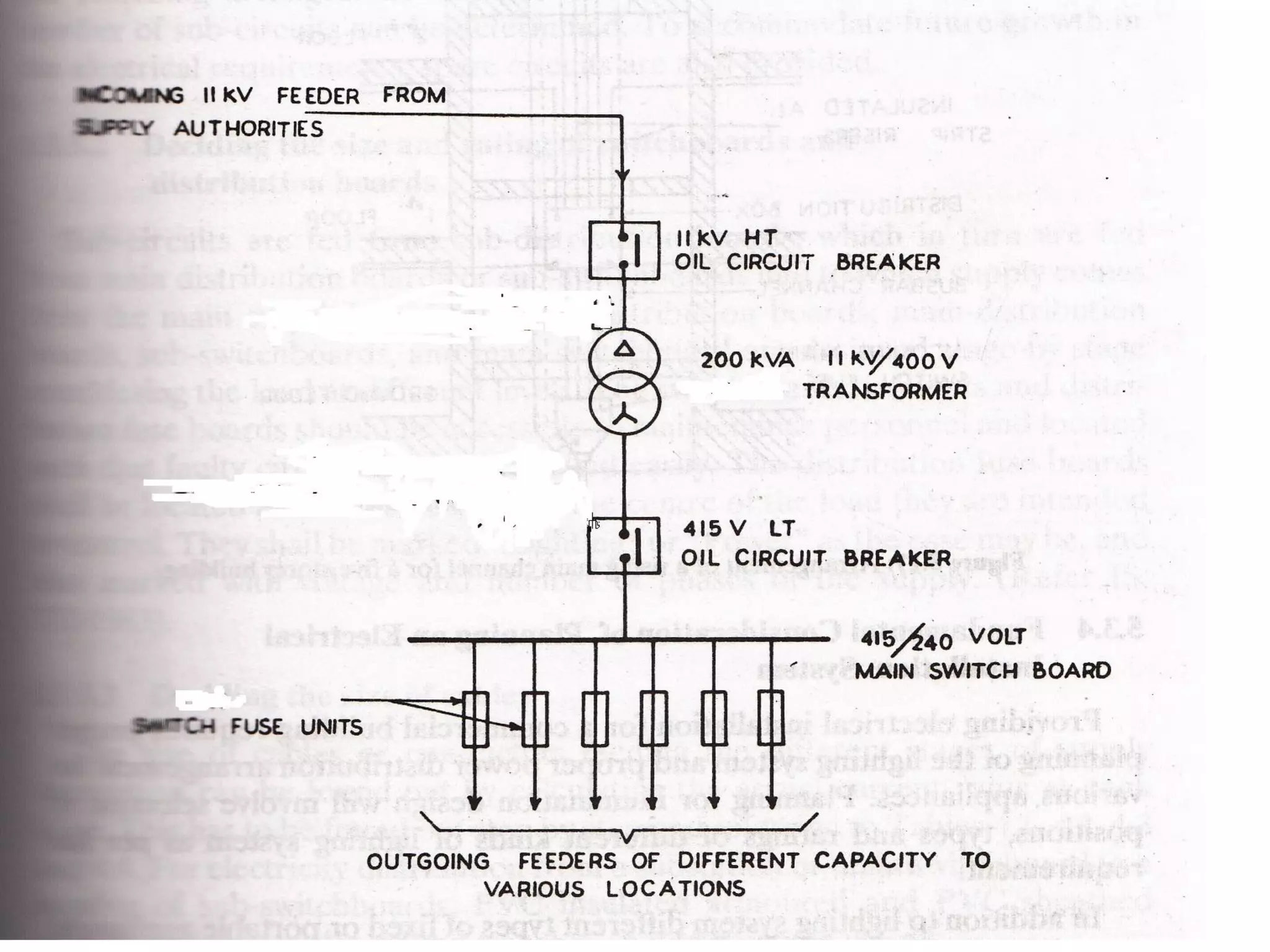
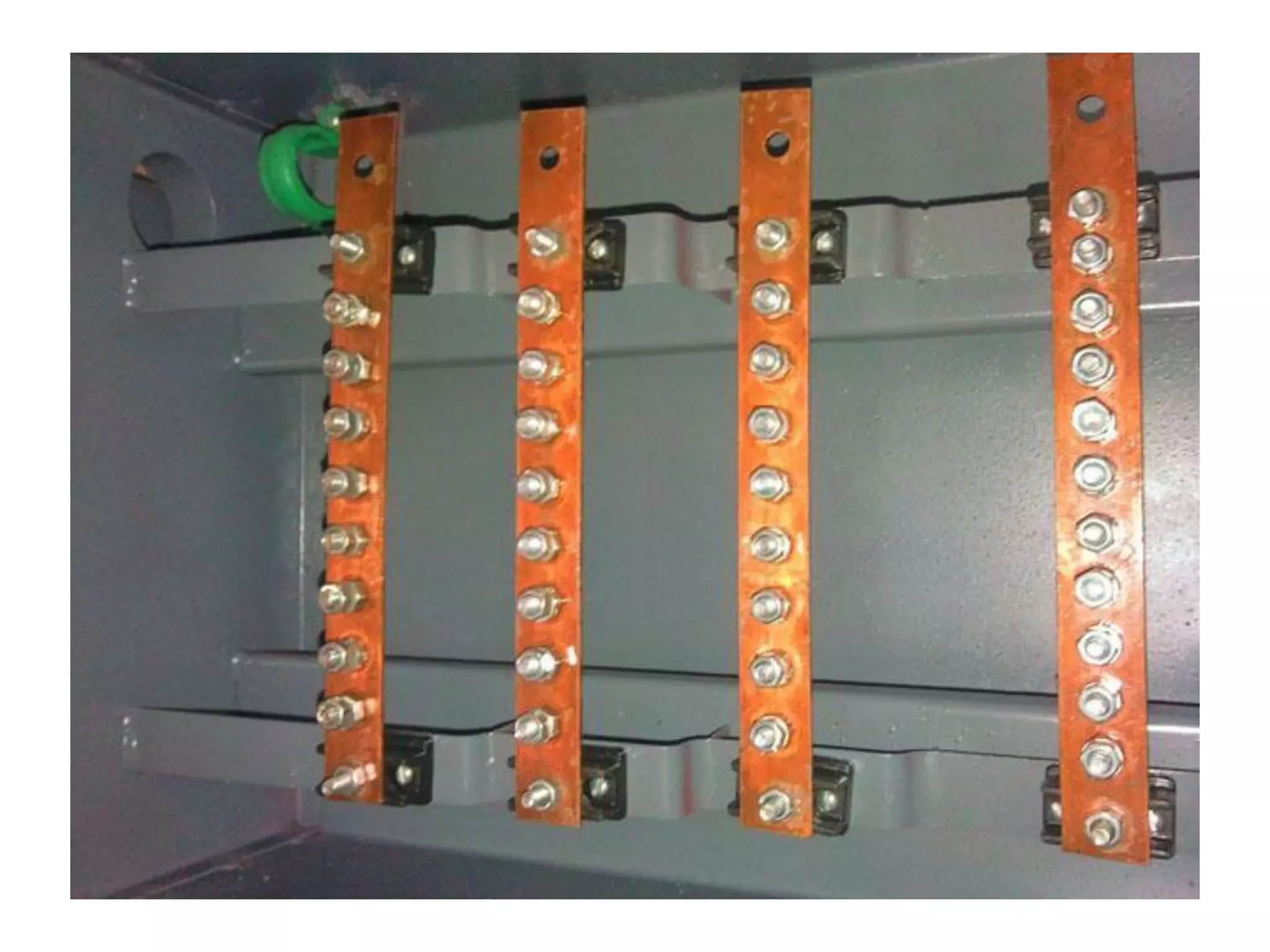
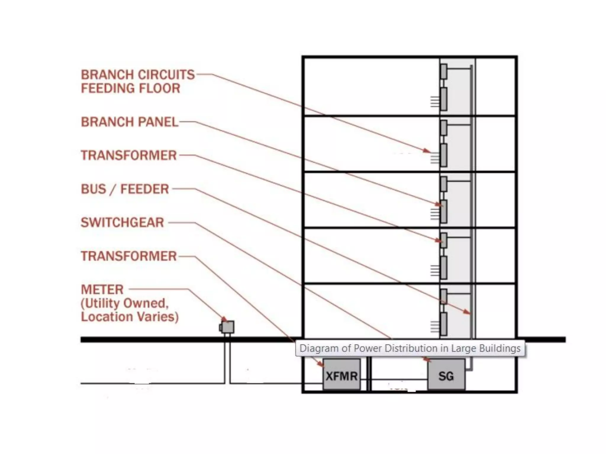
4. Components of electrical distribution systems like transformers, switchgear, distribution boards, and circuit breakers.
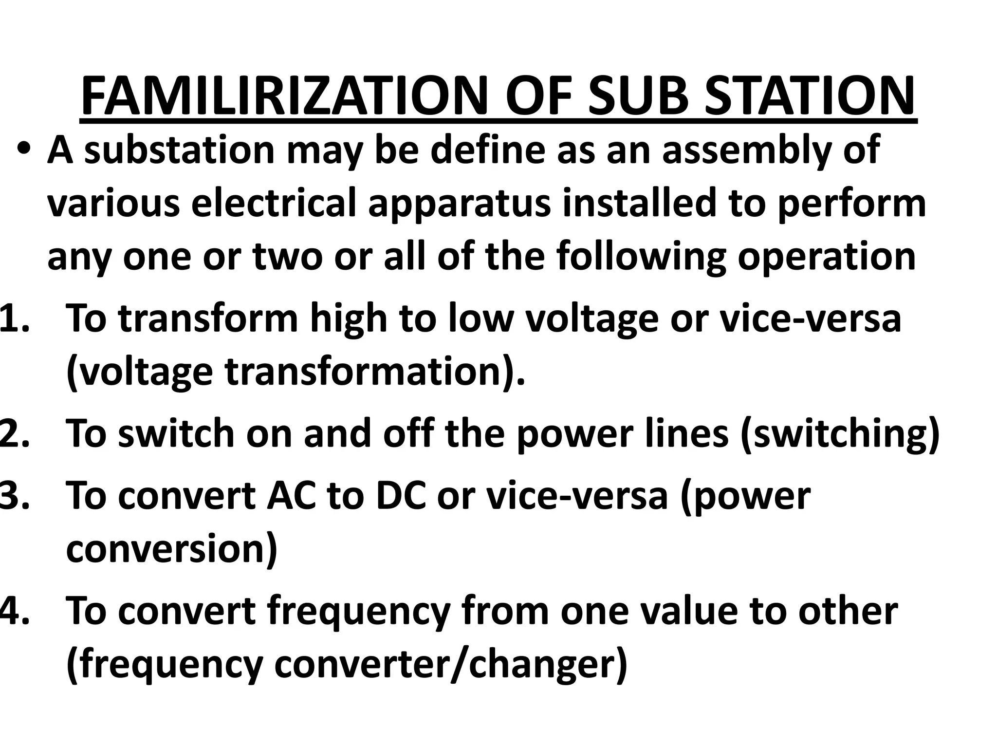
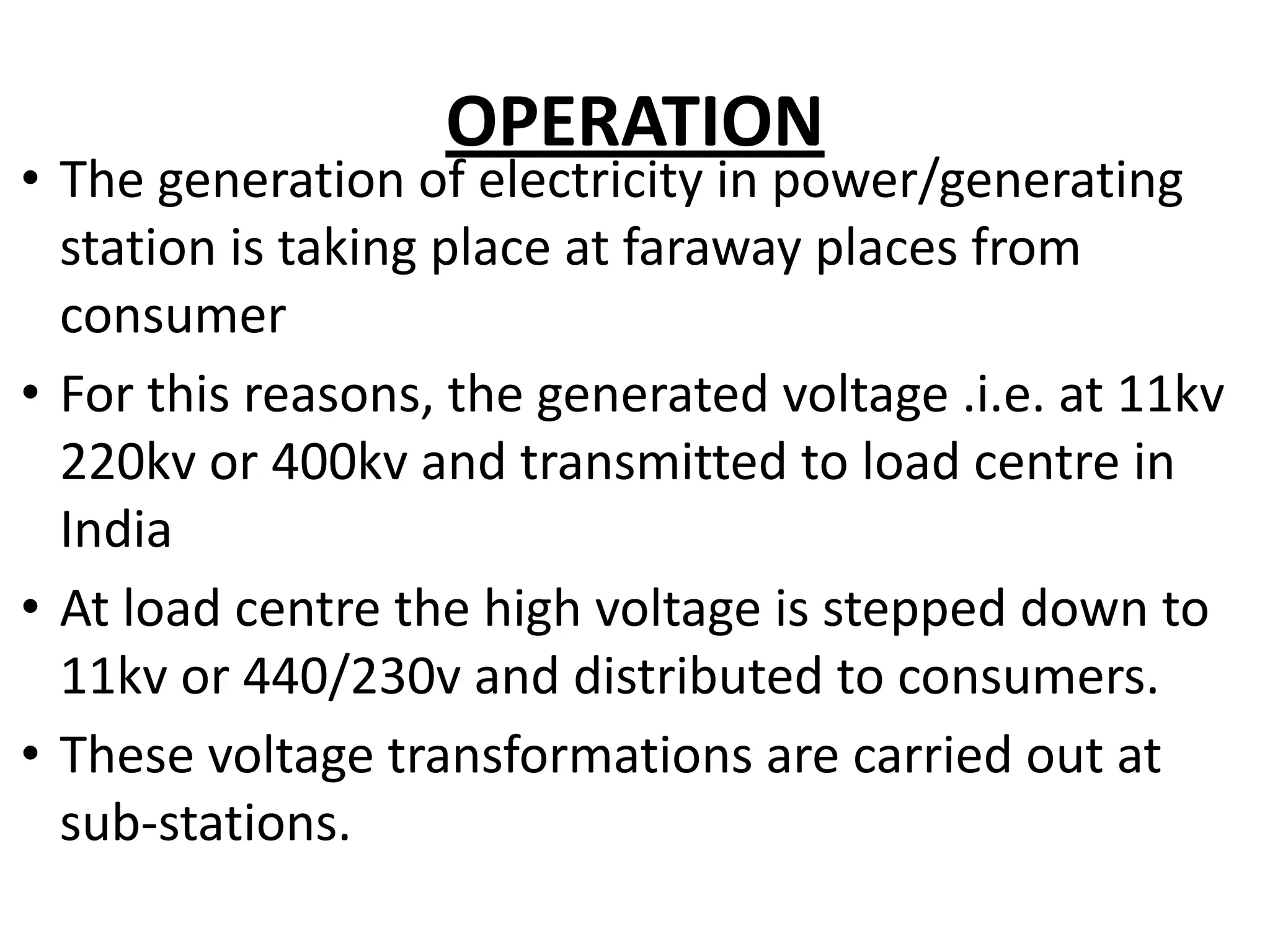
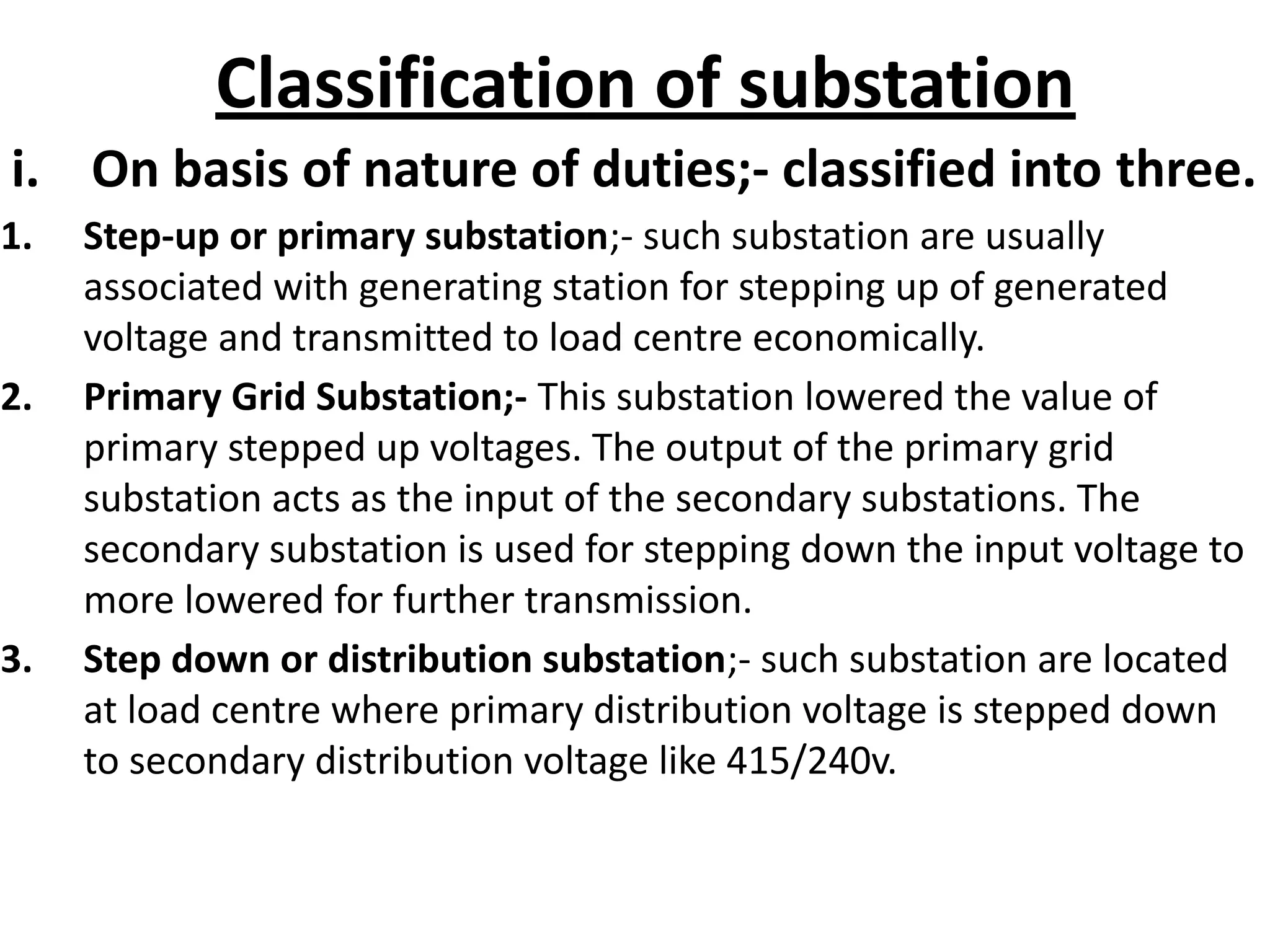
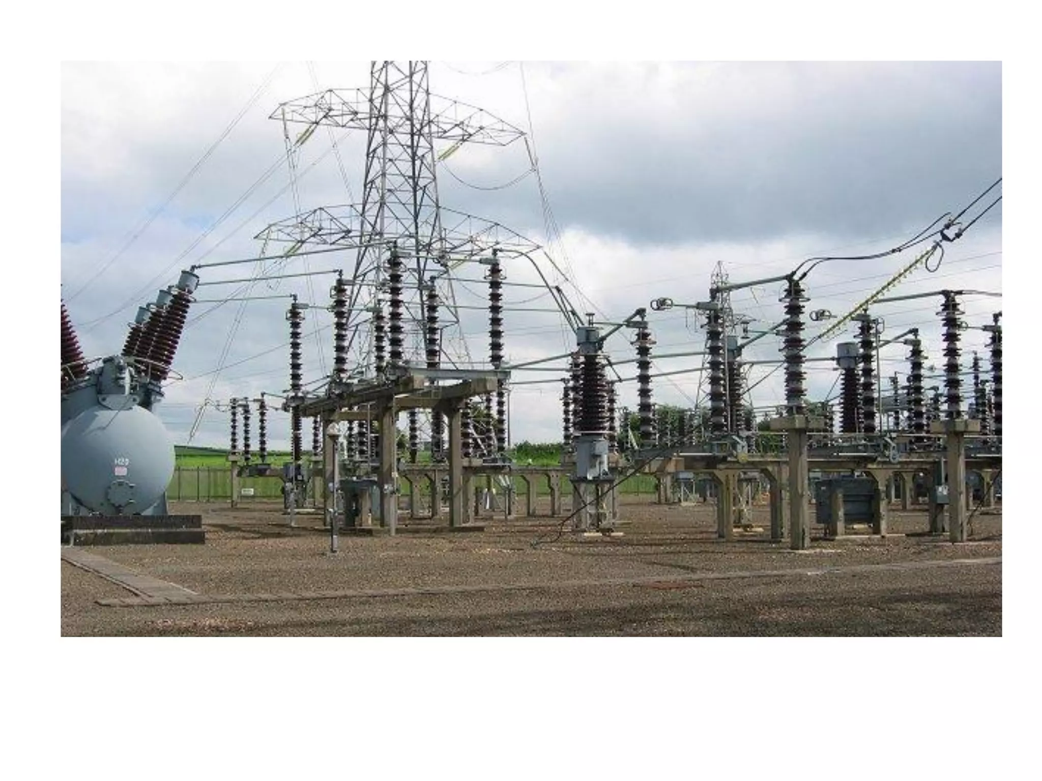
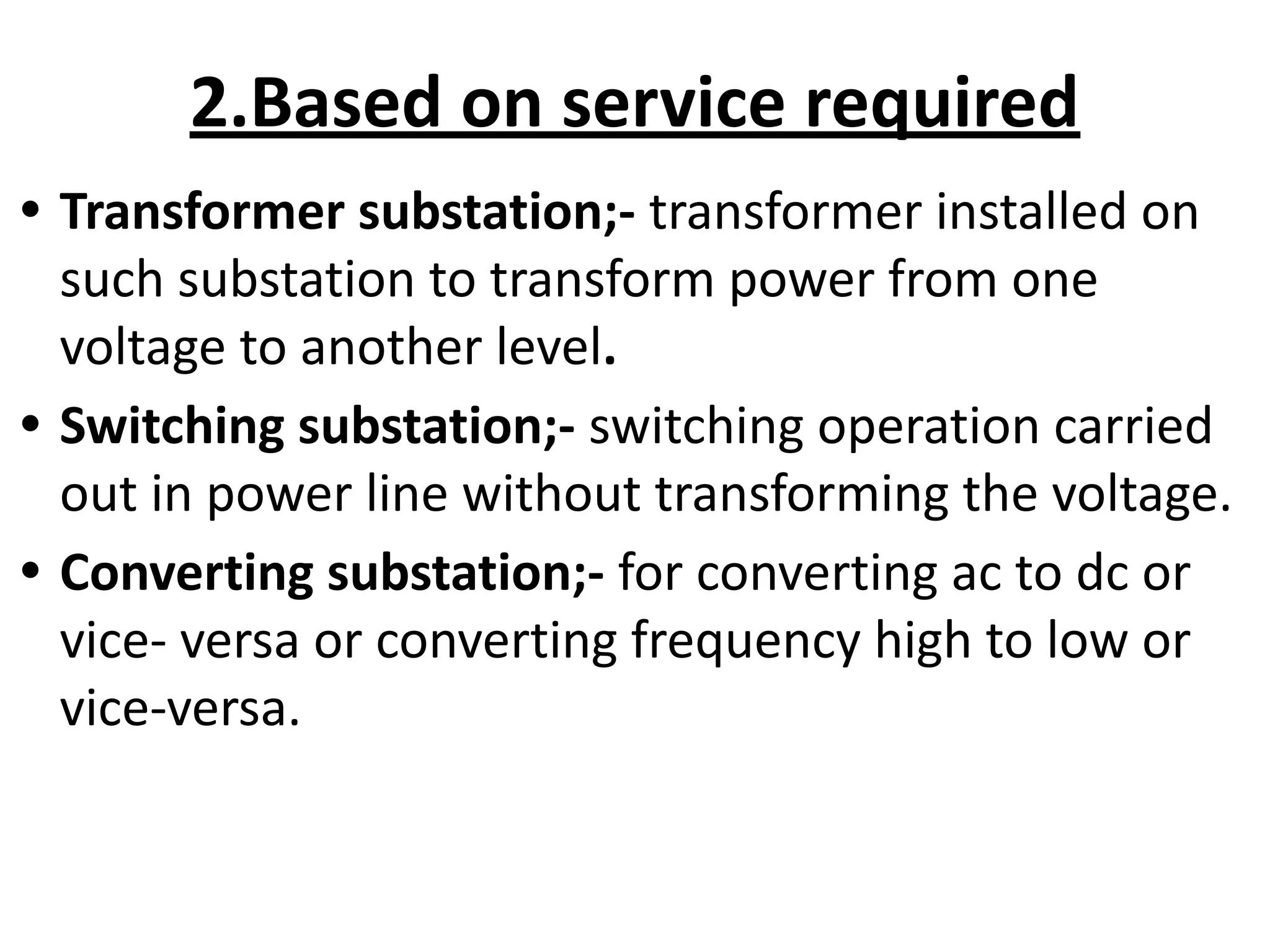
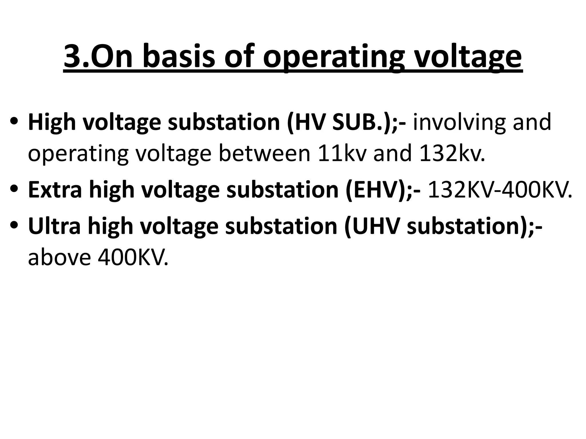
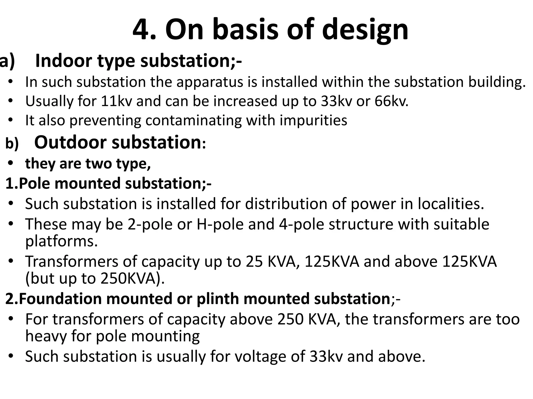
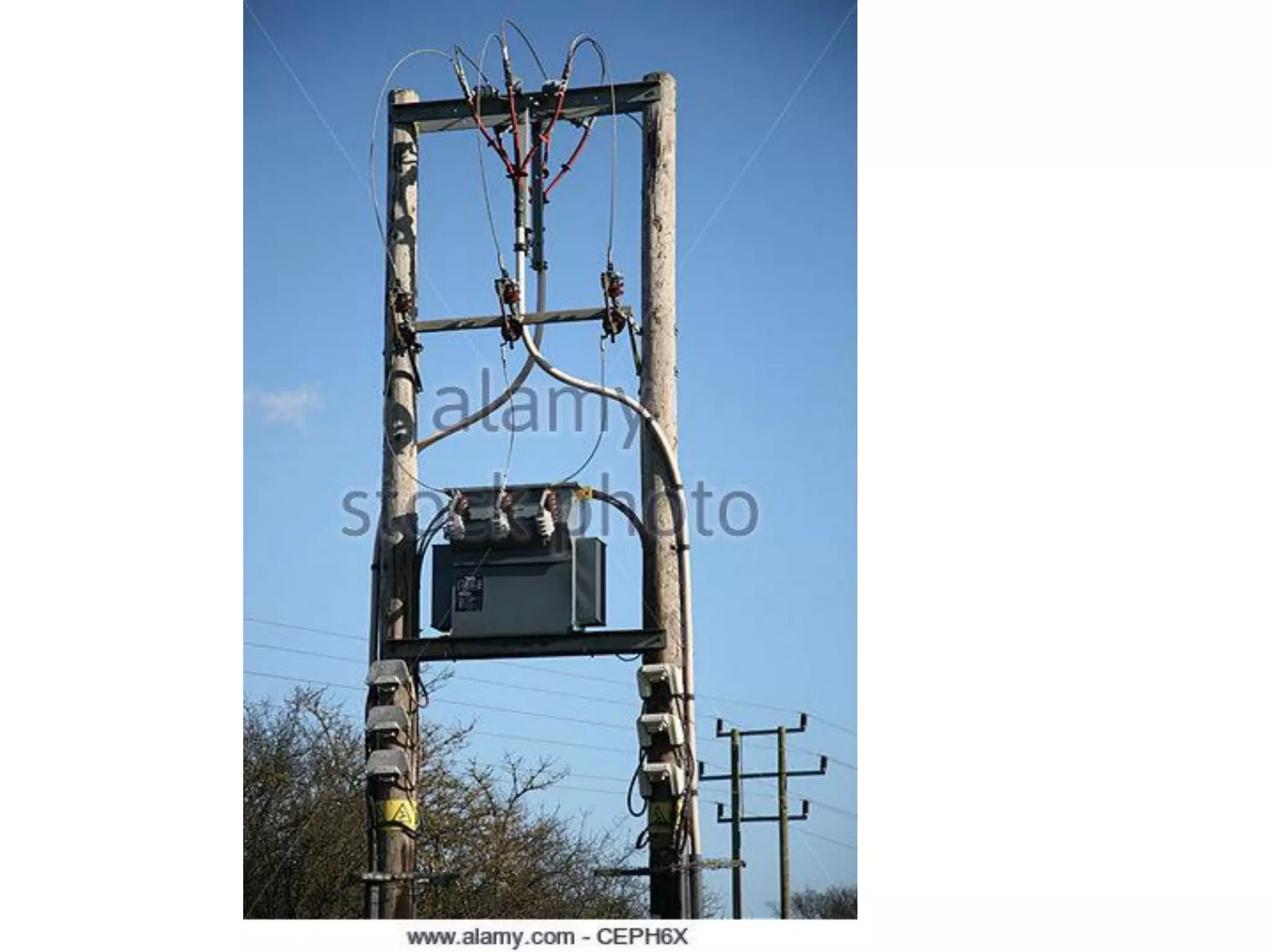
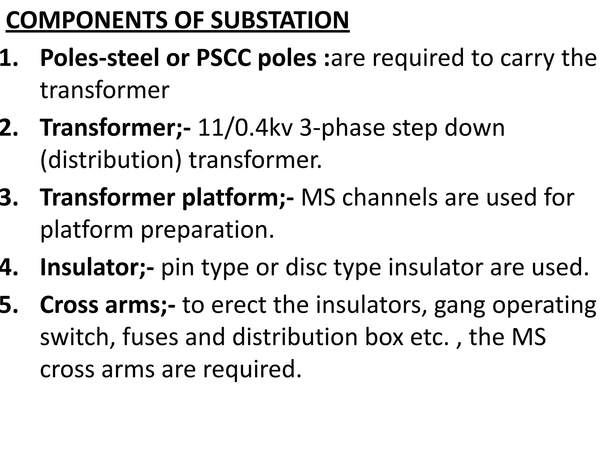
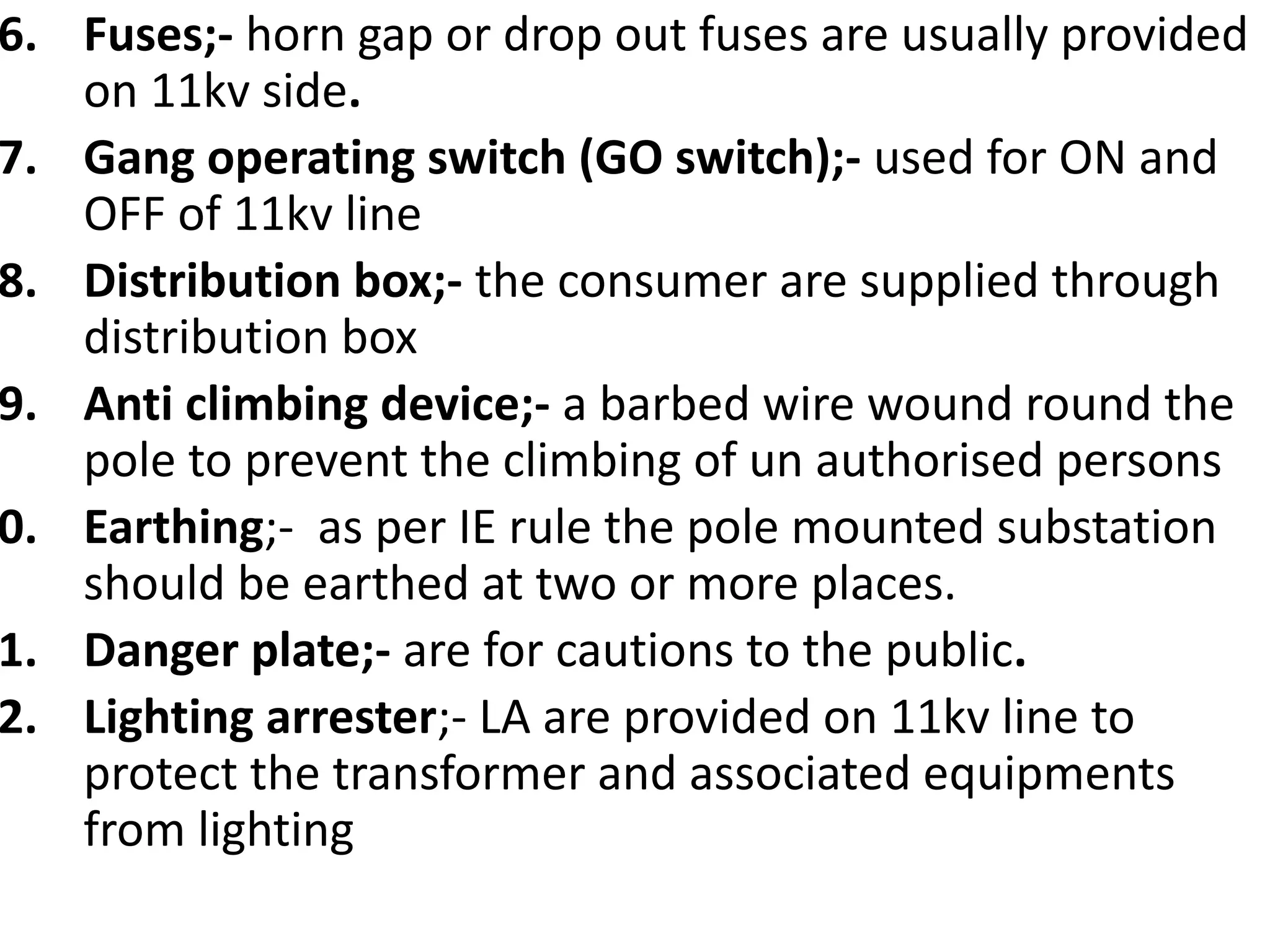
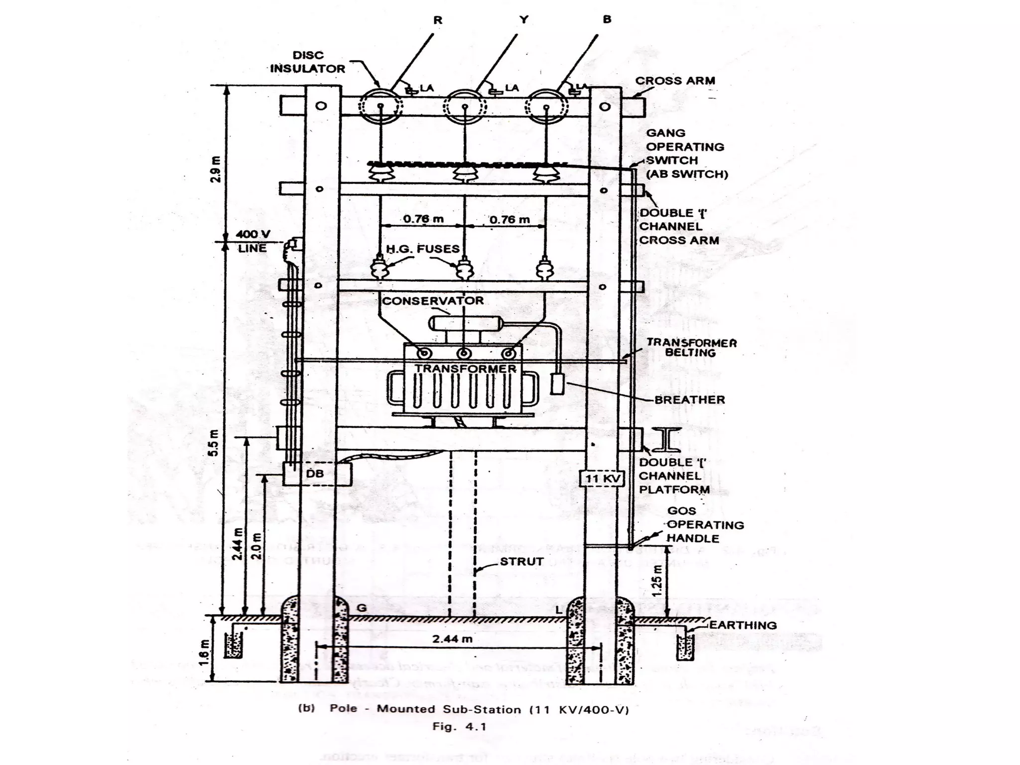
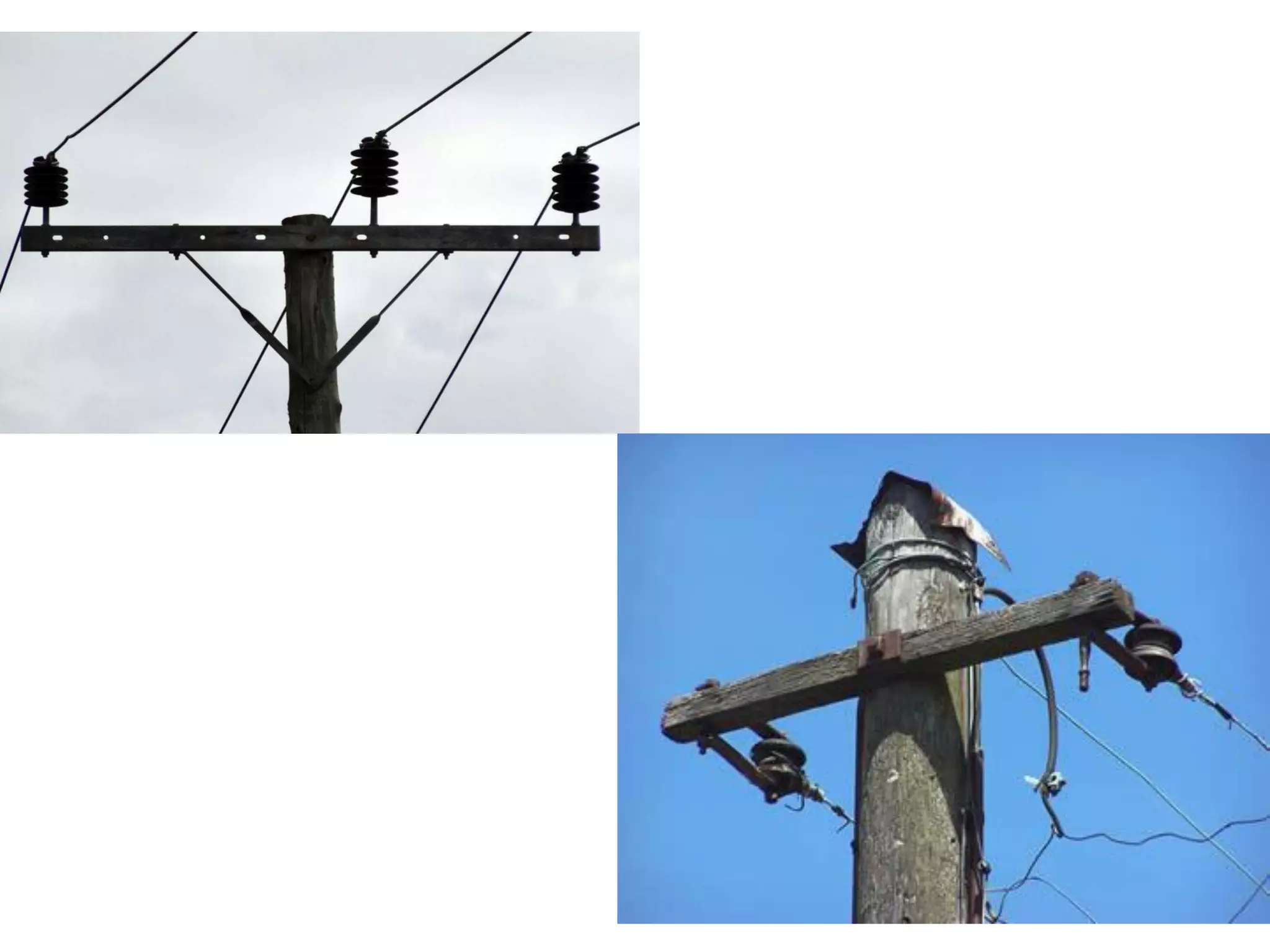
5. Classification and components of electrical substations that transform voltage for distribution to buildings.


![[BROCHURE] Italy Tour Project | @SlideON](https://cdn.slidesharecdn.com/ss_thumbnails/brochure8-251215152319-2805af68-thumbnail.jpg?width=640&height=640&fit=bounds)


