
Recommended
More Related Content
What's hot
What's hot (20)
Similar to Magneto coil unit 2 sathyabama
Similar to Magneto coil unit 2 sathyabama (20)
More from AninVincelyD
Recently uploaded
Recently uploaded (20)
Magneto coil unit 2 sathyabama
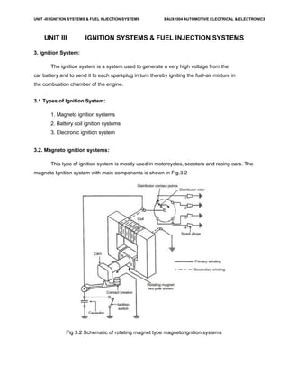
- 1. UNIT -III IGNITION SYSTEMS & FUEL INJECTION SYSTEMS SAUX1004 AUTOMOTIVE ELECTRICAL & ELECTRONICS UNIT III IGNITION SYSTEMS & FUEL INJECTION SYSTEMS 3. Ignition System: The ignition system is a system used to generate a very high voltage from the car battery and to send it to each sparkplug in turn thereby igniting the fuel-air mixture in the combustion chamber of the engine. 3.1 Types of Ignition System: 1. Magneto ignition systems 2. Battery coil ignition systems 3. Electronic ignition system 3.2. Magneto ignition systems: This type of ignition system is mostly used in motorcycles, scooters and racing cars. The magneto Ignition system with main components is shown in Fig.3.2 Fig 3.2 Schematic of rotating magnet type magneto ignition systems
- 2. UNIT -III IGNITION SYSTEMS & FUEL INJECTION SYSTEMS SAUX1004 AUTOMOTIVE ELECTRICAL & ELECTRONICS Magneto ignition system is a special type of ignition system with its own electric generator to provide the required necessary energy for the vehicle system. It is mounted on the engine and replaces all components of the coil ignition system except the spark plug. A magneto when rotated by the engine is capable of producing a very high voltage and doesn’t need a battery as source of external energy. The main components of an ignition coil are Distributor, Condenser, Contact Breaker (CB) points, Ignition Coil. There are two important types of magneto ignition system. They are 1) Rotating armature type and 2) Rotating Magnet type. In the first type, the armature consisting of the primary and secondary windings rotate in between the poles of a stationary magnet. In the second type the magnet revolves and windings are kept stationary is shown in the above figure. A third type of magneto called the polar inductor type magneto, where both the magnet and the windings remain stationary but the voltage is generated by reversing the flux field with the help of soft iron polar projections called inductors. Condensor: The function of the capacitor is to reduce arcing at the contact breaker (CB) points. Also when the CB opens the magnetic field in the primary winding begins to collapse. When the magnetic field is collapsing capacitor gets fully charged and then it starts discharging and helps in building up of voltage in secondary winding. Contact Breaker: It is to be noted that the Contact breaker cam and distributor rotor are mounted on the same shaft. Distributor: Ignition Coil: The main advantage of the high tension magneto ignition system is the production of a very high voltage.Because of the poor starting characteristics of the magneto system invariably
- 3. UNIT -III IGNITION SYSTEMS & FUEL INJECTION SYSTEMS SAUX1004 AUTOMOTIVE ELECTRICAL & ELECTRONICS the battery ignition system is preferred to the magneto system in automobile engines. However, in two wheelers magneto ignition system is preferred due to light weight and less maintenance. 3.3. Battery coil ignition systems: It is used in passenger cars and light trucks. A Battery Ignition system for four cylinder engine where the battery supplies the electrical energy. An ignition switch is used to control the battery current for starting or stopping the engine. The ignition coil transforms the battery low tension current to high tension current required to produce a spark by jumping in a spark plug. The distributor delivers the spark to the proper cylinder and incorporates the mechanical breaker, which opens and closes the primary circuit at exact times. The various units are connected by electrical wiring. The spark plugs provide the spark in engine cylinder. The figure shows battery ignition system for a 4-cylinder petrol engine. It mainly consists of a 6 or 12 volt battery, ammeter, ignition switch, auto-transformer (step up transformer), contact breaker, capacitor, distributor rotor, distributor contact points, spark plugs, etc. The ignition system is divided into 2-circuits namely the Primary Circuit and Secondary Circuit. (i) Primary Circuit : It consists of 6 or 12 V battery, ammeter, ignition switch, primary winding it has 200-300 turns of 20 SWG (Sharps Wire Gauge) gauge wire, contact breaker, capacitor. 53 (ii) Secondary Circuit: It consists of secondary winding. Secondary Ignition Systems winding consists of about 21000 turns of 40 (S WG) gauge wire. Bottom end of which is connected to bottom end of primary and top end of secondary winding is connected to centre of distributor rotor. Distributor rotors rotate and make contacts with contact points and are connected to spark plugs which are fitted in cylinder heads. Working: When the ignition switch is closed and engine in cranked, as soon as the contact breaker closes, a low voltage current will flow through the primary winding. When the contact breaker opens the contact, the magnetic field begins to collapse. Because of this collapsing magnetic field, current will be induced in the secondary winding. And because of more turns of secondary, the voltage goes upto 20000-35000 volts.
- 4. UNIT -III IGNITION SYSTEMS & FUEL INJECTION SYSTEMS SAUX1004 AUTOMOTIVE ELECTRICAL & ELECTRONICS This high voltage current is brought to centre of the distributor rotor. Distributor rotor rotates and supplies this high voltage current to proper stark plug depending upon the engine firing order. When the high voltage current jumps the spark plug gap, it produces the spark and the charge is ignited-combustion starts-products of combustion expand and produce power. When compared to the magneto ignition system, the battery ignition system is more expensive but at the same time it is very highly reliable as it aids in reliable sparking.. Fig 3.3 Schematic of battery ignition systems 3.4. Electronic ignition system: The requirement for higher mileage, reduced emissions and greater reliability has paved the way for development of the electronic ignition systems. Fig 3.4 Schematic of electronic ignition systems 3.5 Relative merits The main advantages of the electronic ignition system are
- 5. UNIT -III IGNITION SYSTEMS & FUEL INJECTION SYSTEMS SAUX1004 AUTOMOTIVE ELECTRICAL & ELECTRONICS It provides better emission control. It provides a reasonable fuel economy. It provides better engine performance. 3.6 Distributorless Ignition System: 3.7 Centrifugal advance mechanisms: Centrifugal advance makes the ignition coil and spark plugs fire sooner as engine speed increases, using spring-loaded weights, centrifugal force, and lever action to rotate the distributor cam. Spark timing is advanced by rotating the distributor cam against distributor shaft rotation. This action helps correct ignition timing for maximum engine power. Basically the centrifugal advance mechanism consists of two advance weights, two springs, and a advance lever. Fig 3.7 Centrifugal advance mechanisms During periods of low engine speed, the springs hold the advance weights inward towards the distributor cam or trigger wheel. At this time there is not enough centrifugal force to push the weights outward. Timing stays at its normal initial setting. As speed increases, centrifugal force on the weights moves them outwards against spring tension. This movement causes the distributor cam or trigger wheel to move ahead. With this design, the higher the engine speed, the faster the distributor shaft turns, the farther out the advance weights move, and the farther ahead the cam is moved forward or advanced. At a preset engine speed, the lever strikes a stop and centrifugal advance reaches maximum.
- 6. UNIT -III IGNITION SYSTEMS & FUEL INJECTION SYSTEMS SAUX1004 AUTOMOTIVE ELECTRICAL & ELECTRONICS The action of the centrifugal advance causes the contact points to open sooner, or the trigger wheel and pickup coil turn off the ECU sooner. This causes the ignition coil to fire with the engine pistons not as far up in the cylinders. 3.8 Vacuum Advance mechanisms: The vacuum advance provides additional spark advance when engine load is low at part throttle position. It is a method of matching ignition timing with engine load. The vacuum advance increases fuel economy because it helps maintain idle fuel spark advance at all times. A vacuum advance consists of a vacuum diaphragm, link, movable distributor plate, and a vacuum supply hose. At idle, the vacuum port from the carburetor or throttle body to the distributor advance is covered, thereby NO vacuum is applied to the vacuum diaphragm, and spark timing is NOT advanced. At part throttle, the throttle valve uncovers the vacuum port and the port is exposed to engine vacuum. The vacuum pulls the diaphragm outward against spring force. The diaphragm is linked to a movable distributor plate, which is rotated against distributor shaft rotation and spark timing is advanced. Fig 3.8 Vacuum advance mechanism The vacuum advance does not produce any advance at full throttle. When the throttle
- 7. UNIT -III IGNITION SYSTEMS & FUEL INJECTION SYSTEMS SAUX1004 AUTOMOTIVE ELECTRICAL & ELECTRONICS valve is wide open, vacuum is almost zero. Thus vacuum is not applied to the distributor diaphragm and the vacuum advance does not operate. 3.9 Spark plug: The spark plug consists of a porcelain insulator in which there is an insulated electrode supported by a metal shell with a grounded electrode. They have a simple purpose of supplying a fixed gap in the cylinder across which the high voltage surges from the coil must jump after passing through the distributor. The spark plugs use ignition coil high voltage to ignite the fuel mixture. Somewhere between 4,000 and 10,000 volts are required to make current jump the gap at the plug electrodes. This is much lower than the output potential of the coil. Spark plug gap is the distance between the center and side electrodes. Normal gap specifications range between .030 to .060 inch. Smaller spark plugs gaps are used on older vehicles equipped with contact point ignition systems. Spark plugs are either resistor or non-resistor types (fig. 2-46). A resistor spark plug has internal resistance (approximately 10,000 ohms) designed to reduce the static in radios. Most new vehicles require resistortype plugs. Non-resistor spark plug has a solid metal rod forming the center electrode. This type of spark plugs is NOT commonly used except for racing and off-road vehicles.
- 8. UNIT -III IGNITION SYSTEMS & FUEL INJECTION SYSTEMS SAUX1004 AUTOMOTIVE ELECTRICAL & ELECTRONICS 3.10 Spark Plug Heat Range and Reach The heat range of the spark plug determines how hot the plug will get. The length and diameter of the insulator tip and the ability of the spark plug to transfer heat into the cooling system determine spark plug heat range. A hot spark plug has a long insulator tip that prevents heat transfer into the waterjackets. It will also bum off any oil deposits. This provides a self-cleaning action. AUTOMOTIVE ELECTRICAL CIRCUITS AND WIRING 58/ 101 A cold spark plug has a shorter insulator tip and operates at a cooler temperature. The cooler tip helps prevent overheating and preignition. A cold spark plug is used in engines operated at high speeds. Vehicle manufacturers recommend a specific spark plug heat range for their engines. The heat range is coded and given as a number on the spark plug insulator. The larger the number on the plug, the hotter the spark plug tip will operate. For example, a 54 plug would be hotter than a 44 or 34 plug. The only time you should change from spark plug heat range specifications is when abnormal engine or operating conditions are encountered. For instance, if the plug runs
- 9. UNIT -III IGNITION SYSTEMS & FUEL INJECTION SYSTEMS SAUX1004 AUTOMOTIVE ELECTRICAL & ELECTRONICS too cool, sooty carbon will deposit on the insulator around the center electrode. This deposit could soon build up enough to short out the plug. Then high voltage surges would leak across the carbon instead of producing a spark across the spark plug gap. Using a hotter plug will bum this carbon deposit away or prevent it from forming. Spark plug reach is the distance between the end of the spark plug threads and the seat or sealing surface of the plug. Plug reach determines how far the plug reaches through the cylinder head. If spark plug reach is too long, the spark plug will protrude too far into the combustion chamber and the piston at TDC may strike the electrode. However, if the reach is too short, the plug electrode may not extend far enough into the cylinder head and combustion efficiency will be reduced. A spark plug must reach into the combustion chamber far enough so that the spark gap will be properly positioned in the combustion chamber without interfering with the turbulence of the air-fuel mixture or reducing combustion action. Figure 2-46.- Sectional view of a (A) non-resistor and (B) resistor spark plug. 3.11 Construction of Spark Plug: 3.12 Types of spark plugs:
- 10. UNIT -III IGNITION SYSTEMS & FUEL INJECTION SYSTEMS SAUX1004 AUTOMOTIVE ELECTRICAL & ELECTRONICS Introduction to feed back carburetor systems: Carburetor is a device used for providing proper air/fuel mixture ratio. The carburetor works on Bernoulli's principle i.e. The faster the air moves, the lower is its static pressure, and the higher is its dynamic pressure. The throttle or accelerator linkage indirectly controls the flow of fuel by actuating the carburetor mechanisms which meters the flow of air being pulled into the engine. The speed of this flow, and therefore its pressure, determines the amount of fuel drawn into the airstream. The latest type of carburetor system is the electronic feedback design, which provides better combustion by improved control of the air/fuel mixture. A three-way converter not only oxidizes HC and CO but also chemically reduces oxides of nitrogen (NOX).If the air/fuel mixture is too lean, NOX is not converted efficiently. If the mixture is too rich, HC and CO does not oxidize efficiently. Monitoring the air/fuel ratio is the job of the exhaust gas oxygen sensor. An oxygen sensor senses the amount of oxygen present in the exhaust stream. A lean mixture produces a high level of oxygen in the exhaust. The oxygen sensor, placed in the exhaust before the catalytic converter, produces a voltage signal that varies with the amount of oxygen the sensor detects in the exhaust. If the oxygen level is high (a lean mixture), the voltage output is low. If the oxygen level is low (a rich mixture), the voltage output is high.The electrical output of the oxygen sensor is monitored by an electronic control unit (ECU). This microprocessor is programmed to interpret the input signals from the sensor and in turn generate output signals to a mixture control device that meters more or less fuel into the air charge as it is needed to maintain the 14.7 to 1 ratio. Whenever these components are working to control the air/fuel ratio, the carburetor is said to be operating in closed loop. The oxygen sensor is constantly monitoring the oxygen in the exhaust, and the control module is constantly making adjustments to the air/fuel mixture based on the fluctuations in the sensor's voltage output. However, there are certain conditions
- 11. UNIT -III IGNITION SYSTEMS & FUEL INJECTION SYSTEMS SAUX1004 AUTOMOTIVE ELECTRICAL & ELECTRONICS under which the control module ignores the signals from the oxygen sensor and does not regulate the ratio of fuel to air. During these times, the carburetor is functioning in conventional manner and is said to be operating in open loop. (The control cycle has been broken.) The carburetor operates in open loop until the oxygen sensor reaches a certain temperature (approximately 600F). The carburetor also goes into open loop when a richer-than- normal air/fuel mixture is required, such as during warm-up and heavy throttle application. Several other sensors are needed to alert the electronic sensor provides input relating to engine temperature. A vacuum sensor and a throttle position sensor indicate wide open throttle. Early feedback systems used a vacuum switch to control metering devices on the carburetor. Closed loop signals from the electronic control module are sent to a vacuum solenoid regulator, which in turn controls vacuum to a piston and diaphragm assembly in the carburetor. The vacuum diaphragm and a spring above the diaphragm work together to lift and lower a tapered fuel metering rod that moves in and out of an auxiliary fuel jet in the bottom of the fuel bowl. The position of the metering rod in the jet controls the amount of fuel allowed to flow into the main fuel well. A less common method to control the air/fuel mixture is with a back suction system feedback. The back suction system consists of an electric stepper motor, a metering pintle valve, an internal vent restrictor, and a metering orifice. The stepper motor regulates the pintle movement in the metering orifice, thereby varying the area of the opening communicating control vacuum to the fuel bowl. The larger this area, the leaner the air/fuel mixture. Some of the control vacuum is bled off through the internal vent restrictor. The internal vent restrictor also serves to vent the fuel bowl when the back suction control pintle is in the closed position. Throttle Body Injection(TBI): TBI fuel injection system is a type of system where the fuel is injected into the throttle body. The throttle body fuel injection system operates by using a single or pair of injectors. The throttle looks like a carburetor without the fuel bowl, the metering jets or the float. This type of fuel injection system consists of only two major castings the fuel body and the throttle body. The fuel body supplies the fuel while the throttle body has a valve that controls the
- 12. UNIT -III IGNITION SYSTEMS & FUEL INJECTION SYSTEMS SAUX1004 AUTOMOTIVE ELECTRICAL & ELECTRONICS flow of air. On the throttle, there are ports that gather signals to relay to the manifold absolute pressure sensor and to the emission control system. TBI Fuel Injection Advantages: It is less expensive than using other types of fuel injection systems. It is easier to clean, maintain and service because there are fewer parts. It is cheaper to manufacture than a port injection system and simpler to diagnose. It also does not have the same level of injector balance problems that a port injection system might have when the injectors are clogged. It greatly improves the fuel metering compared to a carburetor. TBI Fuel Injection Disadvantages: It is almost the same as a TBI carburetor wherein the fuel is not equally distributed to all the cylinders. This means that the air/fuel mixture injected differs for each cylinder. It can cool the manifold much faster causing the fuel to puddle and condense in the manifold. The possibility of condensation is much higher since the fuel travels longer from the throttle body to the combustion chamber. Since the system needs to be mounted on top of the combustion chamber, you're prevented from modifying the manifold design to improve your car's performance. It is a wet system and the mixture of fuel is still based per cylinder. Ref: http://www.carsdirect.com/carmaintenance/ tbifuelinjectionthrottlebodyfuelinjectionsystems10advantagesanddisadvantages Multi port or point fuel injection, Fuel injection systems,
- 13. UNIT -III IGNITION SYSTEMS & FUEL INJECTION SYSTEMS SAUX1004 AUTOMOTIVE ELECTRICAL & ELECTRONICS Injection system controls. Advantages of electronic ignition systems: Types of solid-state ignition systems and their principle of operation, Contact less electronic ignition system, Electronic spark timing control: It is a closed-loop type electronic control device that continuously corrects the ignition timing and in effect it re-tunes the engine some few times every second. By providing the correct spark timing all the time, the fuel consumption is reduced considerably. Setting of Ignition System Disconnect the drive to the contact breaker cover. Loosen the clamp of CB casing and distributor unit. Set the piston of cylinder NO.2 on TDC against a fixed mark on engine casing. Secure the CB camshaft in this position. The ignition timing will be set. Firing Order Setting Rotate the crankshaft in correct direction. Note the order in which inlet valves(or exhaust valve) open. This the firing order of the engine Gap Adjustment of Contact Breaker Turn the engine shaft manually until the contacts are freely open. Move the fixed contact plate with the help of adjustor screw till required gap is achived If gap is not correct, loosen the screws of fixed contact plate. Tighten the screw of distributor securing clamp. References: 1.http://www.seminarsonly.com/mech%20&%20auto/electronicfuelinjectionseminarreportppt.Ph p – for electronic injection