Test Rig for Measurement of Spark Advance Angle and Ignition System Using AT89C51 Microcontroller

An electronic ignition control system for internal combustion engine, notably for motor vehicles, which comprises a rotary member revolving at engine speed and provided with two reference marks Which the position correspond to the maximum ignition advance angle and to the minimum ignition advance angle, respectively , said reference marks defining at least one area on said rotary member, a sensor disposed in close vicinity of said rotary member so as to detect the moments of passage of said references marks and at least one up and down counter for counting pulse, said rotary member further comprising a third references marks separate from the first two reference marks aforesaid so as to define two successive areas scanned in succession by said sensor, while a first up and down counter positively counts the pulse from a first area and negatively counts, during passage of second area the pulse from second clock system adapted to emit pluses at a frequency programmable according to the desired ignition advance law, the resetting of said up and down counter being utilized for producing ignition spark. Finally up and down counter calculates the final value of the advance angle. After calculating the final value of advance angle signal send to the ignition box to ignition coil, and ignition coil operate the spark as per advance angle.

Recommended
More Related Content
What's hot
What's hot (19)
Similar to Test Rig for Measurement of Spark Advance Angle and Ignition System Using AT89C51 Microcontroller
Similar to Test Rig for Measurement of Spark Advance Angle and Ignition System Using AT89C51 Microcontroller (20)
More from IJSRD
More from IJSRD (20)
Recently uploaded
Recently uploaded (20)
Test Rig for Measurement of Spark Advance Angle and Ignition System Using AT89C51 Microcontroller
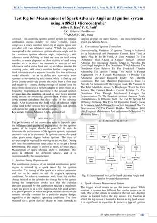
- 1. IJSRD - International Journal for Scientific Research & Development| Vol. 3, Issue 10, 2015 | ISSN (online): 2321-0613 All rights reserved by www.ijsrd.com 282 Test Rig for Measurement of Spark Advance Angle and Ignition System using At89c51 Microcontroller Aditya B. Kale1 Y. R. Patil2 1 P.G. Scholar 2 Proffessor 1,2 AISSMS COE, Pune Abstract— An electronic ignition control system for internal combustion engine, notably for motor vehicles, which comprises a rotary member revolving at engine speed and provided with two reference marks Which the position correspond to the maximum ignition advance angle and to the minimum ignition advance angle, respectively , said reference marks defining at least one area on said rotary member, a sensor disposed in close vicinity of said rotary member so as to detect the moments of passage of said references marks and at least one up and down counter for counting pulse, said rotary member further comprising a third references marks separate from the first two reference marks aforesaid so as to define two successive areas scanned in succession by said sensor, while a first up and down counter positively counts the pulse from a first area and negatively counts, during passage of second area the pulse from second clock system adapted to emit pluses at a frequency programmable according to the desired ignition advance law, the resetting of said up and down counter being utilized for producing ignition spark. Finally up and down counter calculates the final value of the advance angle. After calculating the final value of advance angle signal send to the ignition box to ignition coil, and ignition coil operate the spark as per advance angle. Key words: Ignition Advance Angle, Ignition Coil I. INTRODUCTION The performance of the automotive vehicle depends upon the efficiency and quality of engine used. So the ignition system of the engine should be powerful. In order to determine the performance of the ignition system, important parameters are to be measured. In ignition system, the spark takes place some degree before ignition. The time of advance angle is required for mixing the air and fuel. During this time the combination takes place so as to get a better performance. The angle is known as spark advance angle. Measurement of spark advance angle is important. This angle is different for different vehicles and it is recommended by the manufacturer. A. Ignition Timing Requirements The combustion process of an internal combustion petrol engine is initiated by a spark issued by the ignition controller. The timing of this spark is a critical parameter and has to be varied to suit the engine's operating conditions. To achieve maximum work from the air-fuel charge induced in the cylinder this charge has to be ignited during the compression stroke such that the cylinder pressure generated by the combustion reaches a maximum when the piston is at a few degrees after top dead centre. The piston position at which the peak pressure should occur remains virtually constant for a particular engine design, regardless of the engine's operating conditions. The time required for a given fuel-air charge to burn depends to varying degrees on many factors - the most important of which are detailed below. B. Conventional Ignition Controllers Conventionally, Variation Of Ignition Timing Is Achieved By A Mechanical And Pneumatic Control. Each Time A Spark Plug Is To Be Fired, A Cam Attached To The Distributor Shaft Opens A Contact Breaker. Ignition Advance For Increasing Engine Speed Is Provided By Centrifugal Weights In The Distributor Which Advance The Distributor Cam Relative To The Crankshaft Thereby Advancing The Ignition Timing. This Action Is Further Augmented By A Vacuum Mechanism To Provide The Additional Advance Required Under Part Throttle Conditions. The Inlet Manifold Depression Is Used To Provide An Indication Of The Engine Load. The Vacuum In The Inlet Manifold Moves A Diaphragm Which In Turn Rotates The Contact Breaker Carrier Relative To The Distributor Cam Through Mechanical Linkages. An Approximation To The Required Ignition Advance Angle Characteristics Is Obtained With The Use Of Springs Of Differing Stiffness. This Type Of Controller Usually Lacks In Accuracy And Additional Errors Are Introduced Due To Deterioration Of The Contact Breaker Mechanism With Use. Frequent Maintenance And Adjustment Is Required To Minimize Errors. II. EXPERIMENTAL SET-UP Fig. 1: Experimental Set-Up for Spark Advance Angle and Ignition System Measurement A. Spark Advance Measurement System The trigger wheel rotates as per the motor speed. While rotating, it crosses two different but similar sensors on its path. One of the sensors is located at the top side. Another sensor is located before the top sensor. The location at which the top sensor is located is known as top dead sensor. It is significant in capacitive & inductive type of ignition
- 2. Test Rig for Measurement of Spark Advance Angle and Ignition System using At89c51 Microcontroller (IJSRD/Vol. 3/Issue 10/2015/068) All rights reserved by www.ijsrd.com 283 systems. While starting there is spark before TDC, so that while reaching at TDC, the fuel & air mixture is totally mixed & at TDC the spark voltage is observed. The time difference between the TDC & the before the TDC is known as advance time. It is then converted into angle as the entire between TDC sensor & Before TDC sensor is known as advance angle. Two inductive pickups are used. The sensors senses the metal object the in its vicinity and accordingly, the pulses are generated at the output. Then this pluses are operated the ignition system for spark generation. B. Spark Efficiency System In all type of automobile, engines the sparking of a spark plug is very important in order to start the engine. The ignition systems in use now a days consists of capacitive ignition systems are quite advantages over the inductive because it provides four stroke operation whereas, inductive type ignition provides only two stroke operation. Only one power stroke is there in two stroke engine during two cycles of the crank shaft. Where as in four stroke systems, there is one power stroke, during one cycle. Two strokes are there simultaneously. In two stroke ignition systems suction stroke & exhaust stroke take place simultaneously hence breathing losses are there. Whereas no breathing losses are there in CDI system. In capacitive ignition system the entire fuel in suction stroke is burnt totally hence consumption of fuel is less. In two stroke system fuel consumption is more. Thus CDI systems are more advantageous, because the mechanical efficiency is also better. We measure the spark efficiency of the ignition system, for this we used CDI as we as inductive system. Depending upon the spark efficiency the performance of the ignition system is qualified. In spark ignition engine, the compressed mixture at the end of compression stroke is ignited. But in order to ignite this mixture, there is a spark from the plug. For this purpose spark plug requires high voltage. To achieve the above process ignition system is required. There are three different types’ ignition systems – Battery operated Ignition System (CDI) – Magneto Ignition system – Transistorized Ignition System. The main purpose of battery ignition system is to convert the low voltage current to high voltage current and to supply the high current voltage to spark plug. The following are the main parts of battery ignition system. – Battery – Battery Cable – Ignition Switch – Ignition Coil – Distributor Assembly – High Tension Lead – Spare Plug In battery ignition system (CDI), the supply is taken from battery. The battery supply is first connected to ignition switch. Another terminal of the ignition switch is connected to the side terminal of ignition switch. A wire from another terminal of the ignition coil is connected to the C.B. Point in the distributor assembly. At the same terminal a condenser is conned. H.T. (High tension) wire from the centre of ignition coil is connected to the SKT. In the distributor cap. The HT-Wires from the distributor coil are connected to the spark plug in the combustion chamber. This spark plug is used for better spark. III. ALGORITHM 1) The algorithm for computer program for ignition procedure is shown as follows 2) Detect the positon of the piston. 3) Count the engine speed (Motor Speed) of the first revolution. 4) Display the speed. 5) Fetch the time byte of the map from the microcontroller. 6) Fire the spark plug. (The timing of firing is specified by the time byte for the corresponding speed.) IV. MICROCONTROLLER FEATURES 1) Compatible with MCS-51™ Products 2) 4K Bytes of In-System Reprogrammable Flash Memory – Endurance: 1,000 Write/Erase Cycles 3) Fully Static Operation: 0 Hz to 24 MHz 4) Three-level Program Memory Lock 5) 128 x 8-bit Internal RAM 6) 32 Programmable I/O Lines 7) Two 16-bit Timer/Counters 8) Six Interrupt Sources 9) Programmable Serial Channel 10) Low-power Idle and Power-down Modes V. CONCLUSION Increased fuel mileage, power, performance and reduction in emissions are just some of the benefits as the ignition timing can be advanced or retarded to prevent engine detonation. The aim of this paper was to study effects of ignition timing of a spark- ignition engine and spark efficiency using microcontroller. From In conclusion, a DC motor is used in place of the automobile engine, and a photo sensor is used to detect the revolution of motor. The speed values of the first turn are used to control the timing of the spark ignition. Consequently, by using these simulations the mechanical constructions of vacuum advance, centrifugal advance, the distributor, and the breaker points were replaced. Sensor and microcontroller that makes automobiles monitor and control more effective automobile functions. It shows ability to perform automotive system functions electrically with high degree of accuracy and reliability. ACKNOWLEDGEMENT I am thankful to our respected guide Prof. V. R. Patil, PG Co-coordinator Prof. D. Y. Dhande AISSMS, COE PUNE, for his valuable guidance. I am also thankful to Prof.,A. V. Waghmare HoD, AISSMS,COE, PUNE for continuous support and encouragement throughout project.
- 3. Test Rig for Measurement of Spark Advance Angle and Ignition System using At89c51 Microcontroller (IJSRD/Vol. 3/Issue 10/2015/068) All rights reserved by www.ijsrd.com 284 REFERENCES [1] Nader Raeie et al, “Effects of injection timing, before and after top dead center on the propulsion and power in a diesel engine”, Propulsion andPowerResearch2014;3(2):59–67, 8 July 2014. [2] Santai Hwang et al, “Simulation of Advance Ignition System for A Four Stroke and Single Cylinder Engine Using Photo Sensor And 8751H Microcontroller”, Dept. of electrical engineering technology, CH3000- 7/92/0000-09071992 IEEE. [3] Vijay N. Supe et al, “Survey of Two Wheeler’s Ignition System and Fuel Economy with Embedded Systeml”, International Journal of Electronics Communication and Computer Engineering Volume 5, Issue (4) July, Technovision-2014. [4] Sushant R. Burje et al, “Design and Development of Microcontroller Based Electronic Speed Governor for Genset/Automotive Engine”, International Journal of Engineering and Science ISSN: 2278-4721, Vol. 1, Issue 5 (October 2012), PP 26-33. [5] V. Ganeshan, “Internal Combustion Engines”, Tata McGraw-Hill Education, 2002. [6] Tadashi Hattori et al, “Electronic Ignition Control Apparatus”, United States Patent, 902,966, Jun. 17, 1980. [7] Mamoru Kobashi et al, “Method of Controlling Ignition Timing of an Internal Combustion Engine”, United States Patent, 81,795, Mar. 17, 1981