HARDNESS, FRACTURE TOUGHNESS AND STRENGTH OF CERAMICS
132kV PIPAR CITY GSS - RTU Accessories Pre-SAT Procedure (1).docx
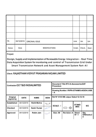
1. FA 04/12/2019 ORIGINAL ISSUE RHM SRK RJN
Status Date MODIFICATIONS Estab. Check. Appr.
Project:
Design, Supply and Implementation of Renewable Energy Integration – Real Time
Data Acquisition System for monitoring and control of Transmission Grid Under
Smart Transmission Network and Asset Management System Part-A1
Client: RAJASTHAN VIDYUT PRASARAN NIGAM LIMITED
Contractor:GE T&D INDIALIMITED
Document Title:RTU & AccessoriesSAT
Procedure
Drawing Number: RVPN-STNAMS-A/GEN-2-008
– A
Original
signed by
DATE NAME SIGN Ref N°:51/D 996 Jaipur Dated 12-12-18
Established 04/12/2019 Rohit Mehra
SCALE: /
STAND
ARD: IEC
Checked 04/12/2019 Samir Kumar
Approved 04/12/2019 Robin Jain Size: A4 Revision: A Sheet
N°: 1
Qty.
OfSheets:3
4
2. STNAMS Part A1-RVPN
RTU & ACCESSORIESSAT Procedure
GE T&D Pages 2 of 33
Rev. A
Table of Contents
1. Introduction................................................................................................................................. 3
1.1. Document Reference...............................................................................................................3
1.2. Prerequisite for SAT ................................................................................................................3
1.3. Glossary..................................................................................................................................5
2. Substation Details...................................................................................................................... 6
3. Site Acceptance Test ................................................................................................................. 7
3.1. Check for BOQ, Technical details, Construction & Wiring as per RTU/SIC drawings..............8
3.2. Check for RTU database & configuration settings ..................................................................9
3.3. Check IP Setting of the RTU ..................................................................................................12
3.4. Check the operation of Analog inputs, Status input & Control output points of RTU ............13
3.5. Check operation of all communication ports of RTU.............................................................14
3.6. Check for communication with master stations or master station simulator ........................15
3.7. Test for downloading of RTU database from Master station .................................................16
3.8. Test for RTU Time synchronization from Master Station or Local GPS .................................17
3.9. Check for auto restoration of RTU on DC power recovery after its failure ............................19
3.10. Test for RTU diagnostics features.........................................................................................20
3.11. Test for RTU SOE feature ......................................................................................................21
3.12. Test for IEC 60870-5 -101/104 & Modbus protocol implemented ...........................................22
3.13. Test for RTU Redundancy .....................................................................................................24
3.14. End to end Testing (between RTU & Scada Master / Master Station Simulator) for all I/O
points..............................................................................................................................................25
3. STNAMS Part A1-RVPN
RTU & ACCESSORIESSAT Procedure
GE T&D Pages 3 of 33
Rev. A
1.Introduction
This document describes the Integrated Site acceptance procedure of the Remote Terminal
Unit (RTU) &RTU/SIC Panels (Including Relays, Transducers& MFT’s) for STNAMS project
for RAJASTHAN VIDYUT PRASARAN NIGAM LIMITED
Site Acceptance Test: Site Acceptance Test (SAT) is the final check of Installed equipment
at Individual site. It is a test performed by end user to determine if the system commissioned
according to the approved engineering drawings & documents.
1.1. Document Reference
Following documents may be referred for SAT.
Approved DRS & Technical Specification for RTU& RTU Panels
Approved BOQ
Approved GA & Wiring Diagram for RTU
Substation Data-list (based on Approved Typical Data-list)
1.2. Prerequisite for SAT
1.2.1. Communication with Scada Master Control Centres
Communication with Scada Master Control Centres i.e. STNAMS CC – JAIPUR,
JODHPUR & AJMER with RTU over IEC-104 protocol where ever applicable. If
communication link is not available at Substation, then Master Station Simulator
software’s can be considered for the testing. This Master Station Simulator software
shall be configured on a Laptop/Desktop.
1.2.2. RTU
Remote Terminal Unit with various cards like PSU, CPU, DIU, DOU, AIU, IOS and ESW
for automation of various signals of the substation like Indications, Alarms, Protection
and station Auxiliary. Should be installed and functional before commencement of SAT.
1.2.3. Relays (CMR, IPR & Dummy CB)
Relays are required for adaptation of various signals i.e. Indications, Alarms, Protection
and station Auxiliary. Should be installed and functional before commencement of SAT.
1.2.4. Transducers (Current, Voltage, Temperature and Tap)
Transducers are required for adaptation of Station DC & Transformers Auxiliaries i.e.
Battery Voltage, Battery Current, WTI, OTI & TPI. Should be installed and functional
before commencement of SAT.
4. STNAMS Part A1-RVPN
RTU & ACCESSORIESSAT Procedure
GE T&D Pages 4 of 33
Rev. A
1.2.5. MFT
MFT’s are used to collect Bay Analog Data i.e. Current, Voltage, Power, PF. Should be
installed and functional before commencement of SAT.
1.2.6. Mechanical Key Interlock
MKI are used to collect Isolator Status. Should be installed and Isolator Data shall report
to RTU.
5. STNAMS Part A1-RVPN
RTU & ACCESSORIESSAT Procedure
GE T&D Pages 5 of 33
Rev. A
1.3. Glossary
Scada Master Front-End Software (e-terracontrol)
Master Station Simulator Third Party Test Analyzer (Vinci / IEC Tester / RPA / ASE)
IEC104 IEC 60870-5-104 Protocol
IEC103 IEC 60870-5-103 Protocol
IEC 61850 IEC 61850 Protocol
IOA Information Object Address
RTU Remote Terminal Unit
MODBUS MODBUS Protocol
IEC 101 IEC 60870-5-101
SIC System Interface Cabinet
IED Intelligent Electronics Device
MFT Multi-function Meter
PSU Power Supply Unit
CPU Central Processing Unit
IOS IO Scanner
DIU Digital Input Unit
DOU Digital Output Unit
AIU Analog Input Unit
RTU Software HUSKY Studio
ESW Ethernet Switch Card
CMR Contact Multiplier Relay
IPR Interposing Relays
MKI Mechanical Key Interlock
6. STNAMS Part A1-RVPN
RTU & ACCESSORIESSAT Procedure
GE T&D Pages 6 of 33
Rev. A
2. Substation Details
Name of the Substation PIPAR CITY Name of Region JODHPUR
Store ID Station Category Type-III
Date:
RVPN Representative
7. STNAMS Part A1-RVPN
RTU & ACCESSORIESSAT Procedure
GE T&D Pages 7 of 33
Rev. A
3. Site Acceptance Test
This section describes the list of the tests that will be performed after Installation & commissioning of
RTU system. Following Tests are required to be performed in SAT.
1. Check for BOQ, Technical details, Construction & Wiring as per RTU/SIC drawings.
2. Check the RTU database & configuration settings.
3. Check IP Settings of the RTU.
4. Check the operation of Analog inputs, Status input & Control output points of RTU.
5. Check operation of all communication ports of RTU.
6. Check for communication with master stations or master station simulator.
7. Test for downloading of RTU database from Master station.
8. Test for RTU Time synchronization from Master Station or Local GPS.
9. Check for auto restoration of RTU on DC power recovery after its failure.
10. Test for RTU diagnostics features.
11. Test for RTU SOE feature.
12. Test for IEC 60870-5 -101/104 & Modbus protocol implemented.
13. Test for RTU Redundancy.
14. End to end Testing (between RTU & Scada Master / Master Station Simulator) for all I/O points.
Annexure - A
Annexure – B
Annexure – C
Annexure - D
8. STNAMS Part A1-RVPN
RTU & ACCESSORIESSAT Procedure
GE T&D Pages 8 of 33
Rev. A
3.1. Check for BOQ, Technical details, Construction & Wiring as per RTU/SIC
drawings
Objective Verify BOQ as per approved drawing and documents.
Procedure
1. Validation of model and make of all the hardware as per approved
BOQ &DRS.
2. Number of equipment’s as per approved BOQ.
3. Validation of the Technical details and Construction & wiring as per
RTU/SIC GA & Wiring Drawing.
4. Visual inspection of all the equipment’s.
Verification 1. All equipment’s are available as per approved BOQ, DRS & GA & Wiring
Drawing (Refer Annexure-A).
Comment Tested & Found OK
Decision
□ Passed
□ Not Complete
□ Failed
GE T&D. Responsible
Signature
Customer Responsible (RVPN)
Signature
Date-
9. STNAMS Part A1-RVPN
RTU & ACCESSORIESSAT Procedure
GE T&D Pages 9 of 33
Rev. A
3.2. Check for RTU database & configuration settings
Objective Check for RTU database & configuration settings.
Procedure
Check RTU Database and configuration setting as follows.
PROTOCOL SUMMARY
SL.No. Description Value Remark
1 ASDU Common Address 1
2 Address Structure (Information) 3 Byte
3 Frame Max Length 253
4 MV Periodic Cycle 5 Sec.
5 Binary Time Size 7 Byte CP56 Time 2a
6 T0: Connection Time Out 30 Sec. N/A
7 T1: APDU Time Out 15 Sec.
8 T2: Acknowledge Time Out 10 Sec.
9 T3: Test Frame Time Out 20 Sec.
10
K: Send Acknowledgement
Frames (APDU)
12
11
W: Acknowledgement Received
Frame (APDU)
8
12 Common Address Size of ASDU 2 Byte
For IEC-
101only N/A
13 Time Synchronisation NA
Locally through
SNTP or IEC
14 Cause of Transmission 2 Byte
For IEC-
101only N/A
10. STNAMS Part A1-RVPN
RTU & ACCESSORIESSAT Procedure
GE T&D Pages 10 of 33
Rev. A
COMMAND PROFILE
SL.No. Description
PULSE
WIDTH
DURATI
ON
CONTROL
TYPE
TIME OUT
DURATION
1 Circuit Breaker 500 ms SBO 3 Sec
2 Isolator 500 ms SBO 20 Sec
3 Tap Changer 500 ms DIRECT 10 Sec
4 Relay Reset 500 ms DIRECT 10 Sec
6 Auxiliaries 500 ms DIRECT 10 Sec
IEC 104 ASDU TYPE
SL.No. Description
ASDU TYPE
ID
Remark
1
Measured Values, Short Floating-
Point Value
13 All Analogs
2
Single Point Information with
Time Tag
30 All SPS
3
Double Point Information with
Time Tag
31 All DPS
4 Single Command 45 All SPC
5 Double Command 46 All DPC
11. STNAMS Part A1-RVPN
RTU & ACCESSORIESSAT Procedure
GE T&D Pages 11 of 33
Rev. A
IEC 104 ADDRESS STRUCTURE
SL.No. Description
Starting
Address
Remark
1 Single Point Status (SPS) 1
2 Double Point Status (DPS) 5000
3
Measurement Value (MV) or
Analog Value (AI)
10000
4 Double Point Control (DPC) 15000
5 Single Point Control (SPC) 17000
Verification All details are configured in the database.
Comment
Tested & Found OK
Decision
□ Passed
□ Not Complete
□ Failed
GE T&D. Responsible
Signature
Date -
Customer Responsible (RVPN)
Signature
Date
12. STNAMS Part A1-RVPN
RTU & ACCESSORIESSAT Procedure
GE T&D Pages 12 of 33
Rev. A
3.3. Check IP Setting of the RTU
Objective Check IP Settings of RTU
Procedure
1. Open Husky Studio Software.
2. Check IP Configuration like IP address, subnet mask, default gateway
configured in database as per IP Scheme.
3. Update final IP details in the attached Annexure – B.
Verification All IP’s configured as per IP Scheme.
Comment
Tested & Found OK
Decision
□Passed
□ Not Complete
□ Failed
GE T&D. Responsible
Signature
Date -
Customer Responsible (RVPN)
Signature
Date-
13. STNAMS Part A1-RVPN
RTU & ACCESSORIESSAT Procedure
GE T&D Pages 13 of 33
Rev. A
3.4. Check the operation of Analog inputs, Status input & Control output points of
RTU
Objective Check the operation of Analog inputs, Status input &Control output points of
RTU/SIC.
Procedure
1. RTU & SIC cubicles and other system shall be energized.
2. Connect Scada Master / Master Station Simulator to RTU over IEC-104
protocol and verify data is reporting.
3. Simulate all digital input at field terminal blocks.
4. Execute commands (DO) from Scada Master / Master Station simulator.
5. Verify analogue in the analogue card of configured RTU with respect to 4
to 20ma the error should be within the limit of 0.5% of the range.Verify
and update the data in Annexure – C.
6. Verify analogue values in between MFT, RTUand Scada master should
be within the permissible error limit of 0.5% of the range. Verify and
update the data in Annexure –D.
Verification RespectiveDigital Inputs, Analog Inputs are reported correctly in the Scada
Master / Master Station Simulator and Respective output Contacts are operated
in SIC panel / Field.
Comment
Tested & Found OK
Decision
□Passed
□ Not Complete
□ Failed
GE T&D. Responsible
Signature
Date -
Customer Responsible (RVPN)
Signature
Date
14. STNAMS Part A1-RVPN
RTU & ACCESSORIESSAT Procedure
GE T&D Pages 14 of 33
Rev. A
3.5. Check operation of all communication ports of RTU
Objective RTU will be configured as per approved DRS, Drawing and All digital input or
digital output or analog inputs shall be simulated. The following check /
validation will be performed for the test under this category.
Procedure
1. Check the communication with MFT on MODBUS protocol on all
the ports that are configured for MODBUS communication.
2. Check the RTU is connected to the SCADA Master / Master station
simulator laptop and communicating over IEC-104protocol.
3. Check the RJ45 port in CPU by connecting laptop for database
downloading.
4. Check and verify
Verification Tested and found OK as per approved DRS & Drawings.
Comment
Tested & Found OK
Decision
□Passed
□ Not Complete
□ Failed
GE T&D. Responsible
Signature
Date -
Customer Responsible (RVPN)
Signature
Date
15. STNAMS Part A1-RVPN
RTU & ACCESSORIESSAT Procedure
GE T&D Pages 15 of 33
Rev. A
3.6. Check for communication with master stations or master station simulator
Objective Check for communication with master stations or master station simulator
Procedure
1. Power On RTU
2. Connect all Scada Master / Master Station Simulator to configured
ports in RTU.
3. Send polling from all Configured Scada master’s or master station
simulator
4. Simulate sample DI and AI from RTU.
5. Execute different type (SPC/DPC) of commands from Master
simulator
6. Check and verify.
Verification Simulated DI and AI must report correctly on all configured masters
simultaneously and Commands should be executed on right contact from
Scada master / Master station simulator
Comment
Tested & Found OK
Decision
□Passed
□ Not Complete
□ Failed
GE T&D. Responsible
Signature
Date:
Customer Responsible (RVPN)
Signature
Date:
16. STNAMS Part A1-RVPN
RTU & ACCESSORIESSAT Procedure
GE T&D Pages 16 of 33
Rev. A
3.7. Test for downloading of RTU database from Master station
Objective Validation of Management of RTU database from remote location.
Procedure
1. Check the Connectivity between Master station / Master Station
Simulator and RTU.
2. Check Scada Master / Master Station simulator and RTU are
communicating over IEC 60870-5-104 Protocol.
3. Open RTU Software at Scada Master / Master Station Simulator
PC.
4. Modify and download the database at RTU from Scada Master /
Master Station simulator PC.
5. Check and verify the new version in RTU properties using RTU
Tools software
Verification Downloading of RTU database from the master station is successful
Comment
Tested & Found OK
Decision
□Passed
□ Not Complete
□ Failed
GE T&D. Responsible
Signature
Date -
Customer Responsible (RVPN)
Signature
Date
17. STNAMS Part A1-RVPN
RTU & ACCESSORIESSAT Procedure
GE T&D Pages 17 of 33
Rev. A
3.8. Test for RTU Time synchronization from Master Station or Local GPS
Objective Check RTU time synchronization either locally or from master station.
Procedure
1. Check the time in RTU by using RTU Software.
2. Check whether time sync pulse will be send using GPS Master
Clock over SNTP. Verify the time in RTU.
3. Disconnect GPS from RTU Change the Time in RTU &
Simulate the events with present time.
4. Check the Time of Event reporting with changed time (Wrong
Time).
5. Now connect GPS to RTU and check the RTU is again
synchronized & check time now.
6. Simulate the event again & check the event time again.
7. Now disconnect GPS & verify that time sync pulse will be send
by Scada Master over IEC-104 Protocol.
8. Disconnect Scada Master from RTU Change the Time in RTU
& Simulate the events with present time.
9. Check the Time of Event reporting with changed time (Wrong
Time).
10. Now connect Scada Master to RTU and check the RTU is
again synchronized & check time now.
11. Simulate the event again & check the event time again.
Verification The Events after Synchronization shall report with correct time in GPS
18. STNAMS Part A1-RVPN
RTU & ACCESSORIESSAT Procedure
GE T&D Pages 18 of 33
Rev. A
Comment
Tested & Found OK
Decision
□Passed
□ Not Complete
□ Failed
GE T&D. Responsible
Signature
Date -
Customer Responsible (RVPN)
Signature
Date
19. STNAMS Part A1-RVPN
RTU & ACCESSORIESSAT Procedure
GE T&D Pages 19 of 33
Rev. A
3.9. Check for auto restoration of RTU on DC power recovery after its failure
Objective
Check for auto restoration of RTU on DC power recoveryafter its failure
Procedure 1. Verify that all RTUs available for SAT are Boot up successfully.
2. Restart the RTU’s by powering OFF & ON main MCB / Switch
Verification 1. Verify that Power LED is up and present in green color.
2. No error log is recorded in the system log.
3. All interface related to the RTU are operational.
4. Check the data starts reporting to connected Scada Masters/
Simulators without any manual intervention at RTU end.
Comment Tested & Found OK
Decision
□ Passed
□ Not Complete
□ Failed
GE T&D. Responsible
Signature
Date -
Customer Responsible (RVPN)
Signature
Date
20. STNAMS Part A1-RVPN
RTU & ACCESSORIESSAT Procedure
GE T&D Pages 20 of 33
Rev. A
3.10.Test for RTU diagnostics features
Objective
Check for RTU diagnostics features
Procedure 1. Husky Studio software with RTU
2. Verify that all the modules are shown in healthy condition (green
Colour) in the software
3. Remove one module from RTU rack
4. Observe that the module is indicated as faulty (Red Colour) in the
software
5. Observe that the values reported by that card (in case of DIU or AIU)
are marked not-topical in the master station.
6. Check the fault-table in software and observe that the module loss is
reported along with time.
7. Observe that the master CPU reports the fault via its LED.
8. Reinsert the module into its slot.
9. Observe that the module is indicated as healthy (green colour) in the
software.
10. Observe that the values reported by that card (in case of DIU or AIU)
are marked topical in the master station.
11. Check the fault-table in software and observe that the module
insertion is reported along with time.
12. Observe that the master CPU clears its LED.
13. Remove both CPUs from the RTU rack.
14. Observe that after a while all the I/O modules report error indications
on their respective facia.
15. Reinsert one CPUin the rack, and observe that the are cleared from all
the modules
21. STNAMS Part A1-RVPN
RTU & ACCESSORIESSAT Procedure
GE T&D Pages 21 of 33
Rev. A
Verification Verify above Diagnostrics features are available.
Comment Tested & Found OK
Decision
□Passed
□ Not Complete
□ Failed
GE T&D. Responsible
Signature
Date
Customer Responsible (RVPN)
Signature
Date
3.11.Test for RTU SOE feature
22. STNAMS Part A1-RVPN
RTU & ACCESSORIESSAT Procedure
GE T&D Pages 22 of 33
Rev. A
Objective Check the sequence of events in the RTU log
Procedure 1. Simulate some of the digital inputs and check the sequence of reporting in
the RTU event log and in the master station
2. Check that time stamping accuracy is 1 ms
3. Check event buffer should be more than 5000 events.
Verification Verify that all events are reporting sequentially in the RTU event log.
Comment Tested & Found OK
Decision
□ Passed
□ Not Complete
□ Failed
GE T&D. Responsible
Signature
Date
Customer Responsible (RVPN)
Signature
Date
3.12.Test for IEC 60870-5 -101/104 & Modbus protocol implemented
23. STNAMS Part A1-RVPN
RTU & ACCESSORIESSAT Procedure
GE T&D Pages 23 of 33
Rev. A
Objective Check IEC 60870-5 -101/104, 61850 & Modbus protocol implemented
Procedure 1. Modbus:
a. Communication with Multiple meters in multi drop configuration
b. Failure of any MFT in the loop should report to RTU
immediately.
c. Different communication speed testing from 300 to 9600kbps
2. IEC 60870-5 -101/104
a. Check configuration of the RTU as protocol convertor.
b. Analog data acquisition: Acquisition of data on ASDU 13
c. Digital data acquisition: Acquisition of data on ASDU 30 for
Single Point & ASDU 31 for Double Point Status
d. Control Command: Check ASDU 45 for Single Point Command
& ASDU 46 for Double Point command Check various
conditions such as
Verification Verify all protocol are configured as per the interoperability table.
Comment Tested & Found OK.
Decision
□ Passed
□ Not Complete
□ Failed
GE T&D. Responsible
Signature
Date -
Customer Responsible (RVPN)
Signature
Date
24. STNAMS Part A1-RVPN
RTU & ACCESSORIESSAT Procedure
GE T&D Pages 24 of 33
Rev. A
3.13.est for RTU Redundancy
Objective RTU will be configured by sample data having Digital Inputs, Digital Outputs &
Analog Inputs. The following check / validation will be performed for the test
under this category.
Procedure
1. Power on RTU system available at the platform.
2. Check RTU’s are configured in Main-Standby Mode
3. Remove the Main CPU and check the communication at master
station / Simulator with Stand-by CPU.
4. Insert Main CPU and Remove the Stand-by CPU and check the
communication at master station / Simulator with Main CPU.
5. Verify that both the CPUs can communicate with a master station
without any manual Intervention at RTU end.
6. Verify that only active CPU receives control command.
7. Verify that the failover time is less than 30 Seconds.
Verification Redundancy function is working fine in RTU
Comment
Tested & Found OK
Decision
□Passed
□ Not Complete
□ Failed
GE T&D. Responsible
Signature
Date -
Customer Responsible (RVPN)
Signature
Date
25. STNAMS Part A1-RVPN
RTU & ACCESSORIESSAT Procedure
GE T&D Pages 25 of 33
Rev. A
3.14.End to end Testing (between RTU & Scada Master / Master Station Simulator)for
all I/O points
Objective RTU will be configured by sample data having Digital Inputs, Digital Outputs &
Analog Inputs. The following check / validation will be performed for the test
under this category.
Procedure
1. Simulate all Input and Outputs from fields as per available RTU
drawings.
2. Check and verify the same at RTU event log as well at Scada
Master / Master Station Simulator.
Verification Verify that all available IO’s are tested and reporting to Scada Master / Master
Station Simulator.
Comment
Tested & Found OK
Decision
□Passed
□ Not Complete
□ Failed
GE T&D. Responsible
Signature
Date
Customer Responsible (RVPN)
Signature
Date
26. STNAMS Part A1-RVPN
RTU & ACCESSORIESSAT Procedure
GE T&D Pages 26 of 33
Rev. A
Annexure – A
System Hardware and Validation & Visual check
RTU CARD Details
Sl.No Device Name Make/Model Device
Serial No.
Qty as per
BOQ
Installed
Qty.
Checked Remarks
1. RTU Synergy/Husky 1 1 checked
2. Extn. Rack Synergy/Husky 1 1 checked
3. GPS As per
Approved DRS
GPS-
B/20/08-66
1 1 checked
RTU CARD Details
Sl.No Card Type Make Channels
Per Card
Qty. as per
BOQ
Installed
Qty.
Checked Remarks
1. Digital I/p Card Synergy 32 Channels 6 6 Checked
2. Digital O/p
Card
Synergy 16 Channels 3 3 Checked
3. Analog I/p
Card
Synergy 12 Channels 1 1 Checked
Panel Details
Sl.No
.
Panel Make Qty. as per
BOQ
Installed Qty. Checked Remarks
1. RTU Panel PYROTECH 1 1 Checked
2. SIC Panel PYROTECH 1 1 Checked
Transducers / MFM Details
Sl.No
.
Device Name Make/Model Device Serial
No.
Qty as per
BOQ
Installed
Qty.
Checked Remarks
1. MFT Rishab
Instruments
1910020163 13 11 checked ACDB LT PANEL
2. 1910064448 T/F-1 BUST PT
132KV
3. 1910020159 CAP BANK-1
33KV
28. STNAMS Part A1-RVPN
RTU & ACCESSORIESSAT Procedure
GE T&D Pages 28 of 33
Rev. A
30.
31.
32.
33.
34.
35.
36.
37.
38.
39.
40.
Sl.No
.
Device Name Make/Model Device Serial
No.
Qty as per
BOQ
Installed
Qty.
Checked Remarks
1. DC Current
Transducer
110V
DC CURRENT
48V
TRANSDUCE
R
Rishab
Instruments
Rishab
Instruments
1910104792
2
2
2
2
Checked
Checked
2. 1910104778
3.
4. 1910104290
5. 1908066591
6.
Sl.No
.
Device Name Make/Model Device Serial
No.
Qty as per
BOQ
Installed
Qty.
Checked Remarks
1. DC Voltage
Transducer
110V
DC Voltage
Transducer
48v
Rishab
Instruments
Rishab
Instruments
1
1
1
1
Checked
Checked
2. 1909069279
3.
4.
5. 1909021161
6.
29. STNAMS Part A1-RVPN
RTU & ACCESSORIESSAT Procedure
GE T&D Pages 29 of 33
Rev. A
Sl.No
.
Device Name Make/Model Device Serial
No.
Qty as per
BOQ
Installed
Qty.
Checked Remarks
1. WTI
Transducer
Rishab
Instruments
1908082410 2 1 checked
2.
3.
4.
5.
6.
Sl.No
.
Device Name Make/Model Device Serial
No.
Qty as per
BOQ
Installed
Qty.
Checked Remarks
1. OTI
Transducer
Rishab
Instruments
1908082452 2 1 Checked
2.
3.
4.
5.
6.
Sl.No
.
Device Name Make/Model Device Serial
No.
Qty as per
BOQ
Installed
Qty.
Checked Remarks
1. TPI
Transducer
Rishab
Instruments
1910062305 2 1 Checked
2.
3.
4.
5.
6.
Weather Sensor
Sl.No Device Name Make/Model Device
Serial No.
Qty as per
BOQ
Installed
Qty.
Checked Remarks
1. Ambient
Temperature
Outdoor
As per
Approved DRS
NIL NIL
30. STNAMS Part A1-RVPN
RTU & ACCESSORIESSAT Procedure
GE T&D Pages 30 of 33
Rev. A
2. Wind Speed NIL
3. Wind Direction NIL
4. Air Humidity NIL
5. Solar
Radiation
NIL
Mech. Key Interlock Box (1 NO, 1 NC Contact)
Sl.No Device Name Make/Model Qty as per
BOQ
Installed
Qty.
Checked Remarks
1. Mechanical
Key Interlock
Box
As Per Approved DRS 3 3 checked
Contact Multiplier Relay
Sl.No Relay Voltage
Level
Make/Model Qty as per
BOQ
Installed
Qty.
Checked Remarks
1. 220VDC As Per Approved DRS Nil
2. 110VDC As Per Approved DRS 158 183 checked
3. 48VDC As Per Approved DRS 2 2 checked
4. 24VDC As Per Approved DRS NIL
5. 230VAC As Per Approved DRS NIL
6. Dummy
Breaker Relay
As Per Approved DRS 1 1 checked
7. Heavy Duty
IPR
As Per Approved DRS 32 30 checked
Signature Signature
(GE T&D India LTD.) (RRVPNL)
31. STNAMS Part A1-RVPN
RTU & ACCESSORIESSAT Procedure
GE T&D Pages 31 of 33
Rev. A
Annexure – B
Station IP Address Device List Implemented
Sl.No. Device Description IP Configured Checked Remarks
1. Main RTU Port -1 10.226.23.114 checked
2. Main RTU Port -2 10.226.23.114 checked
3. Main RTU Port -3 172.27.92.1 checked
4. Main RTU Port -4 172.27.92.3 checked
5. Standby RTU Port – 1 10.226.23.115 checked
6. Standby RTU Port – 2 10.226.23.115 checked
7. Standby RTU Port – 3 172.27.92.2 checked
8. Standby RTU Port – 4 172.27.92.4 checked
9. ESW
10. GPS 172.27.92.5 & 172.27.92.6 checked
Signature Signature
(GE T&D India LTD.) (RRVPNL)
Annexure – C
Hard Analog Validation Format (for WTI, OTI, TPI, DC Current Trd., DC Voltage Trd.,)
Sl.No. Bay Name Actual Injected
Value (mV, mA,
resistance,
Volts)
Value at
RTU
Value at
Master
Station
Verification / Remarks
1. 110V BATTERY VOLTAGE
2. 110V BATTERY CURRENT
3. 110V CHARGER
CURRENT
32. STNAMS Part A1-RVPN
RTU & ACCESSORIESSAT Procedure
GE T&D Pages 32 of 33
Rev. A
4. 48V BATTERY VOLTAGE
5. 48V BATTERY CURRENT
6. 48V CHARGER CURRENT
7. TRANSFORMRMR-1 WTI
8. TRANSFORMRMR-1 OTI
9. TRANSFORMRMR-1 TPI
10. TRANSFORMRMR-1 WTI
11. TRANSFORMRMR-1 OTI
12. TRANSFORMRMR-1 TPI
13.
Signature Signature
(GE T&D India LTD.) (RRVPNL)
Annexure – D
Soft Analog Validation Format (for New Installed MFT’s only, existing MFT’s may have error
more than 0.5% as it is not a part of delivery)
Sl.No. Bay Name Value at
MFT
Value at
RTU
Value at Master
Station
Verification / Remarks
33. STNAMS Part A1-RVPN
RTU & ACCESSORIESSAT Procedure
GE T&D Pages 33 of 33
Rev. A
1. 132/33 k V 20/25MVA TR-1 OK (Existing MFT)
2. 132/33 k V 20/25MVA TR-2 OK (Existing MFT)
3. 132 k V BUS BAR OK (NEW GE MFT)
4. 33kV BUSCOUPLER OK (NEW GE MFT)
5. 33KV ACDB LT PANEL OK (NEW GE MFT)
6. 33KV CAPACITOR-1 OK (NEW GE MFT)
7. 33KV CAPACITOR OK (NEW GE MFT)
8. INCOMER-I (LV) OK (NEW GE MFT)
9. INCOMER-II (LV) OK (Existing MFT)
10. 33KV DANTIWARA OK (Existing MFT RS485
PORT FAULTY)
11. 33KV BINAWAS OK (Existing MFT RS 485
FAULTY)
12. 33KV PHED OK (Existing MFT)
13. 33KV BUCHKALAN OK (NEW GE MFT)
14. 33KV PIPAR CITY OK (NEW GE MFT)
15. 33KV SATIN OK (NEW GE MFT)
16 33kv bus pt OK (NEW GE MFT)
Signature Signature
(GE T&D India LTD.) (RRVPNL)