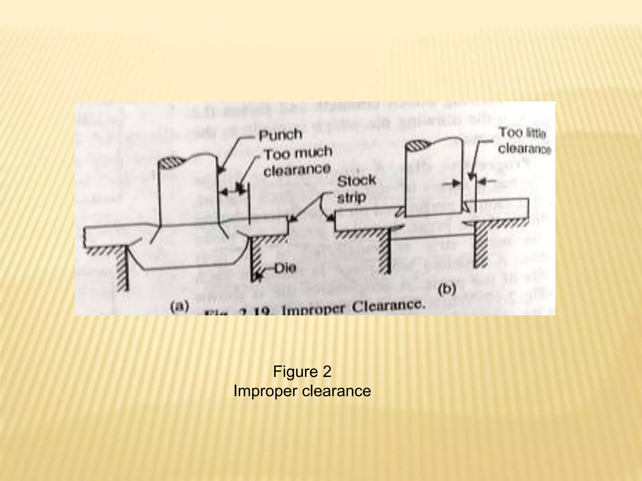
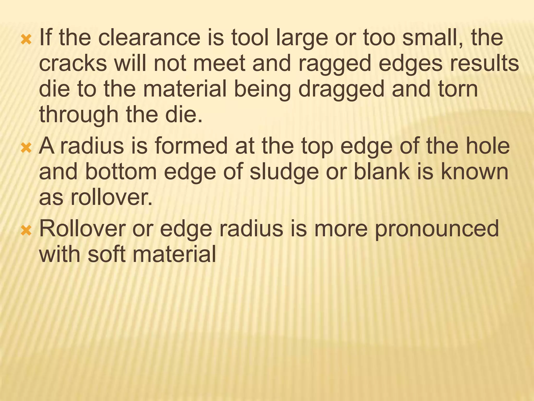
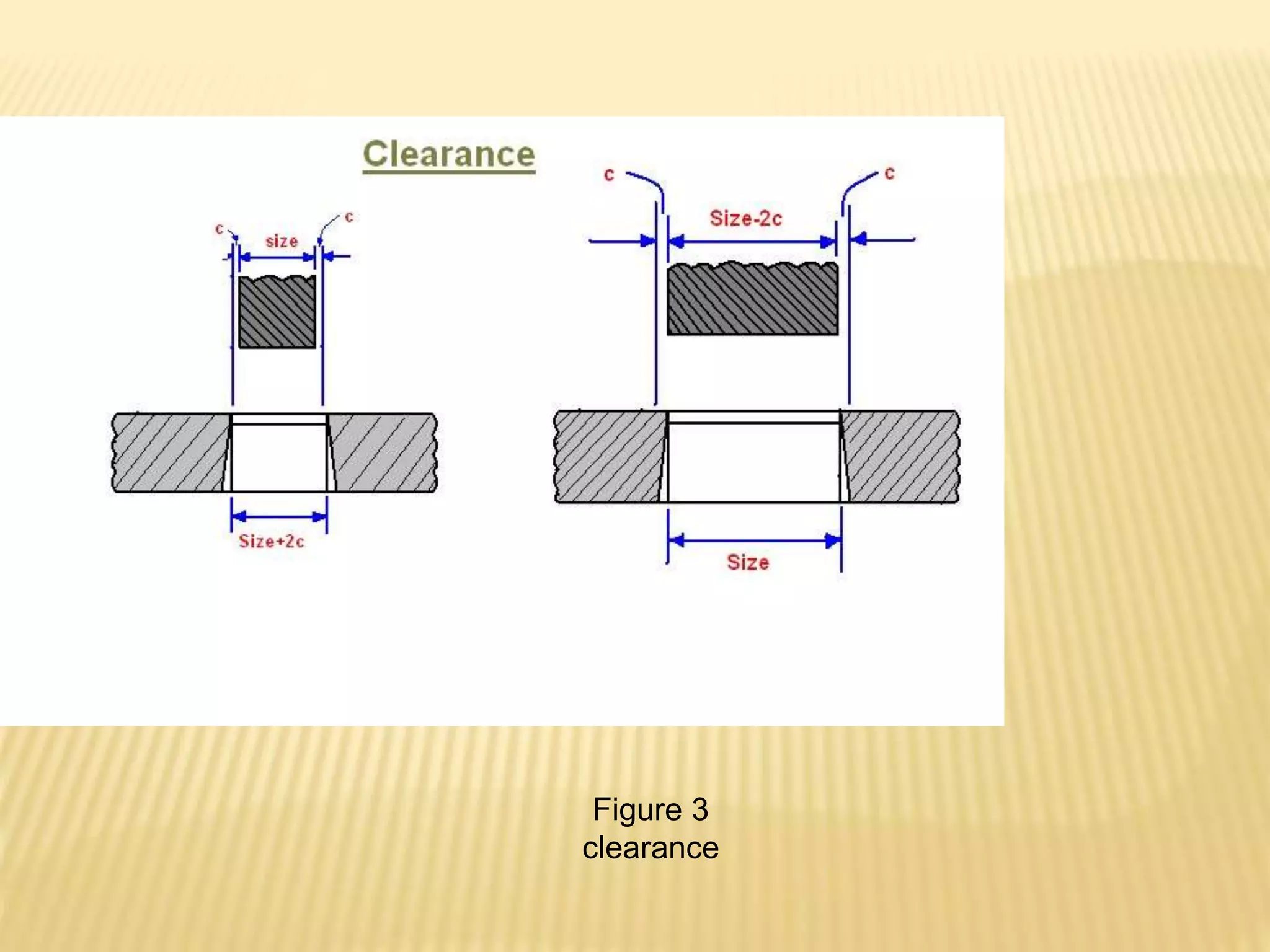
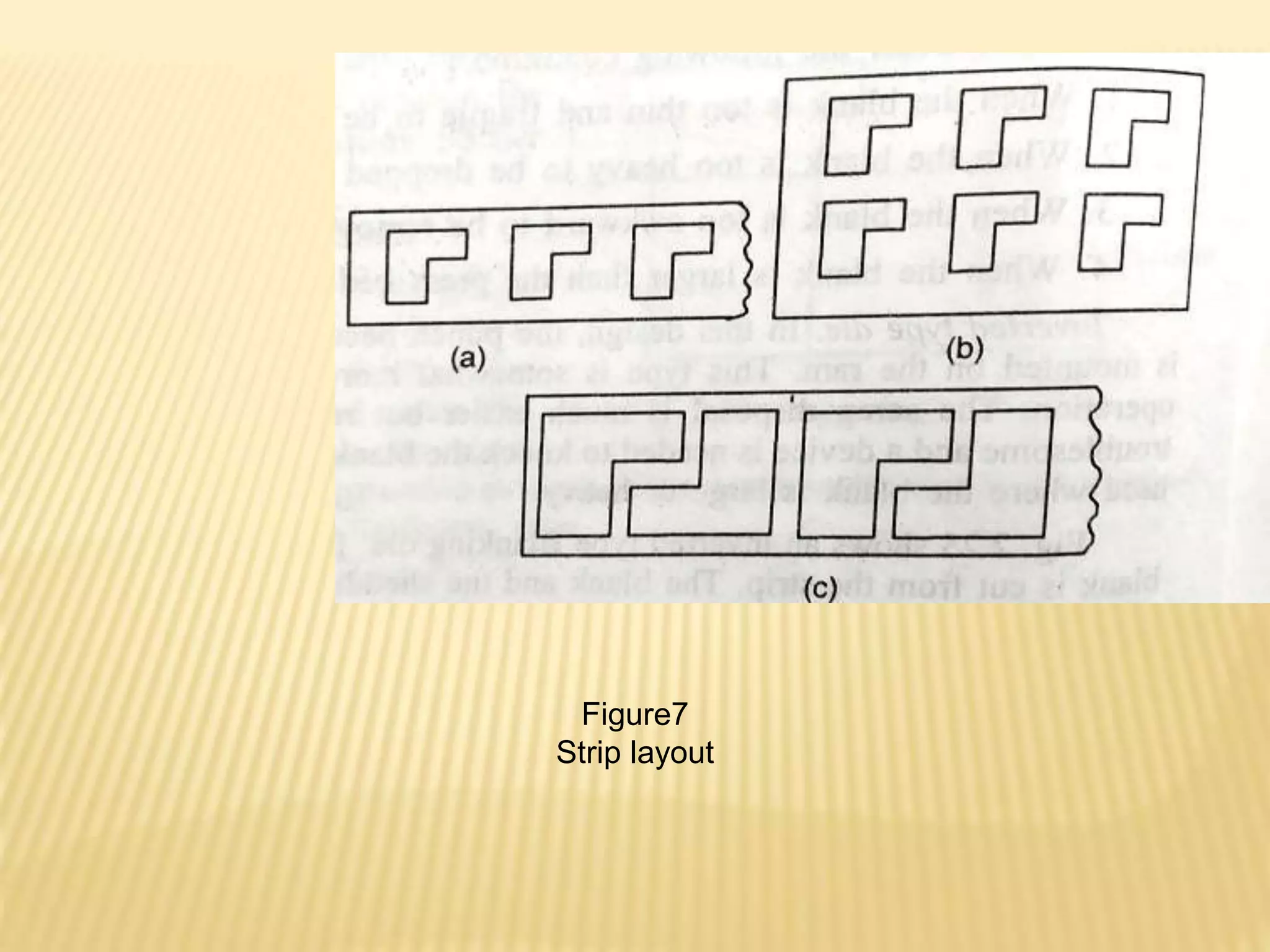
B.TECH 7TH SEMESTER, MECHANICAL
ENGINEERING
TOOL DESIGN
punch and die design
CUTTING ACTION IN A DIE
 The cutting action of sheet metal in press work
is a shearing process.
 Blanking and piercing operations are performed
to prepare stock for further processing.
 The punch is of same shape as of die opening
except that it is smaller on each side by an
amount known as clearance.
 as the punch touches the material and travels
downwards, it pushes the material into the die
opening, the material is subjected to both tensile
and compressive stresses.
FIGURE 1
STRESSES IN DIE CUTTING
 Stresses will be highest at edges at of both
punch and die and material starts crack from
there.
 At this point elastic limit of work material
exceeded, and plastic deformation takes place.
 Reduction in area and fracturing starts takes
place in the reduced area and becomes
complete.
 If the clearance between punch and die is
correct, cracks starts from the punch and die
edge will meet.
Figure 2
Improper clearance
 If the clearance is tool large or too small, the
cracks will not meet and ragged edges results
die to the material being dragged and torn
through the die.
 A radius is formed at the top edge of the hole
and bottom edge of sludge or blank is known
as rollover.
 Rollover or edge radius is more pronounced
with soft material
CLEARANCE
 The difference in dimensions between the mating
members of a die set is called clearance. This
clearance is applied in following manner:
 1: when the hole has to be held to size i.e. the hole in
the sheet metal is to be accurate (punching
operation) , and slug is to be discarded. The punch is
made to the size of the hole and the die opening size
is obtained by adding clearance to the punch size.
 2: In blanking operation , where the slug or blank is
the desired part and has to be held to size, the die
opening size equals the blank size and the punch
size is obtained by subtract.
Figure 3
clearance
 In figure 3, c is the amount of clearance per
side of the side opening
 Physical properties and thickness of stock
material are the factors that determine the
amount of cutting clearance.
 Clearance is generally 5 to 12% of the stock
material thickness.
 Soft material requires more clearance than
hard material
REASON FOR CLEARANCE
 The diameter of the blank or punched hole is
determined by the burnished area.
 On the blank burnished area is produced by
die. Therefore the blank size will be equal to the
size of the die opening.
 Similarly in punching operation the burnished
area in the hole is produced by punch.
Therefore the diameter of hole is same as
punch size.
 Therefore application of clearance on punch or
die will depend on whether the punched hole or
cut blank is the desired product.
 Hence in punching operation(hole in the strip
is desired product) the punched is made to
the correct hole size.
 And die opening is made oversize an amount
equal to the die clearance.
 Similarly if the blank is desired product, the
die opening size is made correct the blank
size and punched is made is smaller size and
punch is made is smaller size an amount
equal to the die clearance.
 Hence punch controls the hole size and die
controls the blank size.
ANGULAR CLEARANCE
 Angular clearance is a draft or taper applied
to the side walls of the die opening.
 It is provided to enable the slug to clear the
die
 It is usually ¼ degree to 1.5 degree per side.
it is sometimes as high as 2 degree,
depending mainly on the stock thickness.
CUTTING FORCES
 In cutting operation as the punch in its down
ward movement enters the materials, it
needs not to penetrates the thickness of the
stock in order to affect complete rupture of
the part.
 The distance which the punch enters into the
work material to cause rupture to take place
is called penetration.
 It is usually given by percentage of the stock
thickness.
 Percentage penetration depends on the material
being cut and also on the stock thickness.
 When a hard and strong material is being cut ,
very little penetration of punch required for
fracture.
 for a softer material, penetration will be grater.
 For soft aluminium it is 60% of t.
 For 0.15% carbon steel annealed it is 38% of t.
 percentage penetration also depends on stock
thickness. Being smaller for thicker sheets and
grater of thinner sheets
 Pressure required to shear the material in
blanking and shearing operation is given by
 Fmax. =πD t 𝝉s for circular blank diameter D
and thickness t, 𝝉s in N/mm2 is the shearing
strength of the material.
 Fmax =P t 𝝉s for others, Where P is the
perimeter of the blank
 Shear strength is taken from tables
ENERGY IN PRESS WORK
 Energy in press work or the work done to make a cut
is give ideally as
 E= Fmax × punch travel
E = Fmax × k × t
Where k is the percentage penetration required to
cause penetration.
To allow for energy lost in machine friction and pushing
slug through the die etc, the above equation get
modified
E = Fmax × k × t × C where C accounts for extra energy
required.
METHODS OF REDUCING THE CUTTING FORCE
 In cutting operation ,if bottom of the punch
and top of the die block lie in parallel plane,
the blank cut the sheet metal by shearing it
simultaneously along the whole perimeter.
 This produces a very high punch force
exerted over for a very short duration. Result
in shock.
 To reduce this impact force, gradual cut is
provided instead of sudden cut.
 This is done by two methods
Figure 4
Effect of shear on cutting force
 The working face of the punch or die are
ground off so that it does not remain parallel to
horizontal plane but inclined to it.
 This angle of inclination is called shear.
 This reduces the area in shear at any one time
and maximum force is much less.
 It may be reduces as much as 50%.
 In figure 4a shear is zero i.e. cutting edges are
parallel. the force diagram shows steep rise at
maximum load and then sudden release load.
Figure 4 Application of shear on punch and die
 In figure 4b the face of the punch is ground off
so that shear=t/3, the cutting action starts at the
leading edge of the punch and gradually spread
to the rest of the punch.
 In this maximum force is reduced and the
energy needed to complete the cut is same. In
this the travel of punch is more than previous
case.
 in figure 4c shear=t/1 in this when leading edge
travelled the stock through a distance t, the
trailing edge will starts making the contact.
 Maximum force will be half when shear is zero.
 The provision of shear distorts the material
being cut.
 When shear is on the face of the punch, punch
can not be flat.
 When shear is on the die, piercing can not be
flat.
 hence for blanking operations shear is
provided on the die face and for piercing
operations shear provided on the punch.
 Where ever possible double shear should be
used on punch and die face, so that two shear
face neutralizes the side thrust.
 Effect of shear on cutting force can be
determined by comparing the work done with
the shear and without shear.
 Work done=area under the curve
= maximum punch force × punch travel
If the shear on cutting tool is zero, then
Punch travel= (%age penetration) × material
thickness
Work done= Fmax× k × t
Where k is the percentage penetration required to
cause rupture.
 If shear is provided on the punch or die then
 Punch travel=k × t + I
 Where I is the total inclination on the die or
punch in cm.
 therefore work done= F× ( k × t + I )
 Where F is the actual cutting force and it will be
less than Fmax
 Since the work done remains the same,
therefore comparing both work done
 F× ( k × t + I ) =Fmax× k × t
 F= (Fmax× k × t)/ ( k × t + I )
MINIMUM DIAMETER OF PIERCING
 To punch a hole without failure of punch, the
compressive strength of punch should at
least equals to the force necessary to
fracture the material.
 If 𝝉s is the shear strength of the material, σc
 Is the compressive strength of the punch
material and d is the smallest diameter hole
to be pierced and t is the thickness, then
 Piercing pressure= πd t 𝝉s
 Strength of punch σc =π/4 × d2
 πd t 𝝉s = π/4 × d2
d= 4 × 𝝉s × t/ σc
If it is assumed that If σc =2𝝉s , then d= 2t.
i. e minimum diameter of can be punched is
twice the stock thickness.
MINIMUM SIZE OF PUNCHED HOLES DEPENDING
ON THEIR SHAPE
 Minimum size of punched hole depending upon their shape , given
below
 = 0.7 to 1.2 for soft steel
 = 0.9 to 1.5t for steel
 = 1.75 to 2t for Ti alloy
 =0.6 to 0.9t for brass and copper
 = 0.5 to 0.8t for zinc
 = 0.4 to 0.7t for Bakelite and textolite
 = 0.3 to 0.6t card board and paper
 Punching force for holes which are smaller than stock thickness are
given by

where d and t are in mm,σt is the tensile strength in N/mm2
BLANKING DIE DESIGN
 Types of blanking die
1. The drop through die
2. The inverted die
 Drop through die: in this die, the die block assembly mounted on the
bolster plate or press bed and punch in press slide.
 The blank drops through the die opening and clearance hole provided
in the bolster plate and press bed.
 Design is easy and economical to build and maintain and fast in
working.
 Not suitable in following condition
a. When the blank is too thin or fragile to be dropped very far
b. When the blank is too heavy to be dropped to be dropped very far.
c. when the blank is larger than pres bed opening.
Figure 5
Figure 6
INVERTED DIE DESIGN
 In this punch becomes the lower stationary
part and die is mounted on the ram.
 This type of die is more complicated, more
costly and slower in operation.
 Scrap disposal is easy but removal of blank
from die opening is troublesome and device
needed to knock out the blank out of die
opening.
STRIP LAYOUT
 In design first step is prepare the blanking layout i.e.
to layout the position strip of work piece in and their
orientation of with respect to each other. This is called
strip layout. Factor affect the strip layout are
a) Economy of material
b) Direction of material grain
c) Strip or coiled stock
d) Direction of burr
e) Press used
f) Production required
g) Die cost
ECONOMY OF MATERIAL
 Figure 7 shows the different ways of
arranging the blank.
 Figure 7a shows the arrangement of single
row and single pass.
 Figure 7b shows the strip either feed twice,
once for each row or double blanking have to
applied.
 % age material utilization may be some what
increased
Figure7
Strip layout
 figure 7c shows a single row double pass strip,
called stock nesting.
 In this strip passed through die once, turned
over passed through die second time.
 Nesting considerably reduces the scrap.
 Another important consideration in strip layout is
distance between nearest point of blank and the
edges of the strip.
 To prevent the scrap from twisting and wedging
between the punch and die, this distance must
be increased with material thickness.
 General rule is that to keep this distance
called web at least 1.5 times the material
thickness.
 Various terms related strip layout are shown
below
 Distance between blank and edge of strip as
back scrap and find by equation
 a= t+ 0.015 h
 Distance between successive blank and
edge of strip as scarp bridge is b give by
table
Material thickness in mm b in mm
0.8
0.8 to 3.2
Over 3.2
0.8
t
3.2
Figure 8 strip layout
Table 1
 Feed or advance or the length of one piece
needed to produce in one blank is
s= w +b
 The number of blank can be produced in one
length can be found as
 N = (L – b)/s
 Scarp remaining at the end of one length of
strip may be calculated as
 Y= L – (N s+b)
MATERIAL UTILIZATION
 It is defined as
 η= area of the blank cut/ area of material
available
 η=B/A × 100
 %age scrap= (A – B)/A
 Area available per blank = feed × stock width
 %age utilization η= w× h/(w +b)(d+2a)
 Η should not less than 70% for economic
working
DIE BLOCK
 Die block is the female half of the two mated
tools which carry the cutting edge.
 It is subjected to extreme pressures and die
wear. Hence die should be made of superior
quality of steel tools.
 A simple layout is as shown figure 9. The die
block may be of solid or sectional
constructional depending on the size of and
contour of die block.
Figure 9
Figure 10
 If dies opening is small and contour is simple
a solid die block is choice.
 Sectional dies are made if contours are
complicated and can be broken in to section
of simple geometric shape which can be
easily assembled.
 Maintenance of die is simple and less costly
because if one section is happens to crack or
chip only particular section to be replaced.
 Die block thickness :
 The minimum thickness of the die block
depends upon the strength required to resist the
cutting forces and depend upon the type and
thickness of the material.
 Die thickness may be obtained below
a) Die thickness= 19 mm for blank perimeter ≤ 75
mm
b) Die thickness= 25 mm for blank perimeter = 75
mm to 250 mm.
c) Die thickness= 31 mm for blank perimeter
>250 mm
 Die thickness may be obtained from table.
 When parts are extremely hard and tough
material, die thickness may be increased by
3mm.
 For Bakelite, brass or other soft material
thickness of die can be reduced by 3mm.
 Fastening of the die block: die block is
secured either to the die shoe or bolster plate.
Size of usually not calculated. These may be
chosen
 By formula screw diameter= 0.5 t for t ≤ 19 mm
 screw diameter= 0.4 t for t>19 mm.
 Along the screw dowel pins are also used for
alignment purposes. They are usually located
near the diagonally opposite corner of the die
block, for maximum locating effect.
 Diameter of dowel pins is taken equal to be
equal to the outside diameter of fastening
screw.
 Two and only two dowel pins should be provided
in the die block for permanent positioning.
PUNCH DESIGN
 Punch must be perfect mate to the die block
opening, the size of the working surface of the
punch is obtained by subtracting the total
clearance from the desired size of the blank.
 punch is usually provide the with a wide flange
or shoulder to facilitate mounting and prevent its
deflection under each load.
 The minimum length of punch should be such
that it extends far enough to die block opening
to ensure complete shearing of the blank.
 Maximum length of the punch can be
calculated as
 Where E is the modulus of elasticity.
 Punched are made up of good grade steel,
hardened and ground. Hardness is
recommended is Rockwell C 100
BACK UP PLATE
 For small punches the back up plates is
provided between the punch plate and punch
holder. Pinch plate fits closely over the body of
the body of the punch and it holds it in proper it
in proper position.
 it is provided to take the back pressure of the
punch head.
 When punch does not have flange or shoulder It
prevents the pushing of punch into the softer
punch holder, thus becoming loose.
Figure 11
 Criteria for providing the back up plate is depends on
the compressive stress on punch given as p= F/A
 Where A is the cress-section area of punch.
 A back up plate is provided if p exceeds the 245
N/mm2 .
 Back up plate is used if punch diameter is less than
four time the stock thickness.
 Thickness of back plate depend upon stock
thickness.
 For thickness of stock material up to 2 mm , thickness
of should be about 3mm.
 and for thicker stock it should be 6 mm.
METHOD OF HOLDING THE PUNCH
 Mounting of punch does not create any
problem. Being relatively bigger they are
made with flanges, that are doweled into
position and directly fastened to the punch
holder by screw without the use of punch
plate and sometimes the back up plates.
 When used, the thickness of punch plate
should be 1.5 times the punch diameter
CENTRE OF PRESSURE
 In case of irregular shaped punch the
summation of irregular shearing forces on one
side of ram may greatly exceed the force on the
other side. This result in the bending moment in
the press ram and undesirable deflection and
misalignment
 Therefore it is necessary in case of irregular
shaped punches to find out exact centre of
pressure and layout the position on punch
holder in such a way that the centre line of
press ram exactly pass through centre of
pressure of blank.
 This centre of pressure is the centroid of the
line perimeter of the blank.
 It should be noted it not the centroid of the
area of the blank. Centre of pressure can be
found by following procedure
STRIPPER DESIGN
 After the blank has been cut by punch on its
down word stroke, the scrap has a tendency to
expand.
 On the return stroke of the punch scrap strip
has a tendency to adhere to the punch and be
lifted by it.
 This action interfere the feeding of the stock
through the die.
 Device which remove the strip from the blank or
die is called stripper.
TYPES OF STRIPPER
 1 fixed stripper
 2. spring loaded stripper
 Fixed stripper attached to a fixed height over
the die block. Height should be sufficient to
permit the sheet metal to be fed freely.
 Length and width of stripper plate should
same as the die block.
 in simple die it fastened with this same
screw and dowel pins which are used for die
block.
Figure 12
 Thickness of the stripper plate usually is 9.5
mm to 16 mm.
 Formula used for finding stripper plate
thickness
 Where are w and t thickness of stock strip
SPRING LOADED STRIPPER
 This type is used on large very thin and highly ductile
materials.
 In this the stripper plate is mounted over compression
spring and suspended by bolts from punch holder.
 The stripping force may vary from 2.5 to20% of
cutting force. However mostly used values are
 5 to 10%.
 Stripping force may also be calculated with formula
FS= S Pt kN
 Where P and t are in mm and S is stripping constant
S= 0.0105 for low C-steel
STOCK STOP
After each blanking operation, strip has to
advance a correct distance. The device used for
this purpose is called stock stop.
Types of stock stop
i. Stop pin
ii. Finger stop
iii. Pawl type automatic stop
iv. Automatic stop
Figure 13
Figure 14
STOCK GUIDE
 Stock guide is the space provided in the die
block, through which stock strip is guided as it
fed into the die.
 Design of stock stop depends upon the type of
stripper
 In the state of Fig. 1, it is very difficult for the
material to enter the guide. As a
countermeasure for this, a material guiding
section is provided at the entrance to the guide
as shown in Fig. 2.

Figure 15
 The form shown in Fig. 16(a) is an extremely obvious
shape of an escape. Although there is no problem
when the material width and plate thickness are of an
easy-to-handle size, if the material becomes wider or
the plate becomes thicker, which is a state referred to
commonly that the material is oversized, working
becomes difficult with the shape of (a). If a step is
provided in the guide as shown in Fig. 16(b), it is
possible to place the material first on the bottom plate
of the guide and then to insert it in the width of the
guide, and hence the work becomes easier.
 In Fig. 17, using a side pusher ,the material is pushed
to one side, thereby restricting the material from
moving due to the variations within the tolerance of
the material width.
Figure 16
Figure 17
STRIP FEEDING
 Strip feeding is either done manually or
mechanically(automatic feeding). Manual
feeding is suitable only for low production or
with press operating at low values of strokes.
 Modern press operates at 200 to 300 strokes
per minutes. For such cases manual feeding is
not possible. For this strip is to prepared in coil
and first step is unwinding of coil for this two
method are used
 a) reel b) coil cradle
 Reel is considered better as it does not damage
the strip, reel may or may not power driven.
 In case of cradle the strip is supported on the
outside diameter of cradle. The coil locates
against the rollers and due to this scratches
may from the coil.
 Second step in stock feeding is straightening of
the uncoiled strip. This is done to remove the
wrinkle and curvature from the strip. For
straightening of this it is passes through the
series of roller.
KNOCKOUTS
 A knockout is used to eject the work piece
from the die cavity as the work-piece may get
jammed in the die cavity due to friction.
Knockout may be actuated by spring or by
positive acting knockout pin and bar
arrangement.
 The knockout pin usually leads through
shank. It may be a pin or double pin fastened
to a pad or collar above the shank.
Figure 18
DIE SET
 Die shoe, punch holder together with two or
more guide post constitutes a die set.
 The die shoe and the punch holder are made
of C.I , cast steel and rolled steel. For smaller
dies cast iron is used and for larger or
special die set Cast steel and rolled steel
are used.
 For average range of die set the diameter of
guide post varies from 2.5 cm to 7.5 cm.
BOLSTER PLATE
 When many dies are run in the same press
at different time, wear occurring on the bed is
high
 Bolster plate is incorporated to take this
wear. It is a flat steel, 50- 100 mm thick. It is
provided with T slots running from front to
back.
DESIGN PROCEDURE OF BLANKING DIE
 Step 1
 In design of press tool first too first step is the
preparation of sketch incorporated all
elements of drawing.
 Step 2
 Determine the punch and die opening
diameters considering whether the operation
is blanking or piercing.
 Step 3
 Design the die block as regards its overall
dimensions and surface area and select a die
set available for the particular die block
dimensions and decide the number size location
of the dowel pins and allen screw.
 Step 4
 Provide arrangement for fixing the punch in the
retainer. Choose one considering wether it is
blanking or piercing punch
 Step 5
 Provide stock stop ,stock guide and suitable
design stripper and provide dimension to
each and also its exact location on the die
block or the die shoe.
 Step 6
 Next step prepare the dimensioned assembly
drawing which should show the following
views.
Figure 19

punch and die design-1.pptx

  • 1.
    B.TECH 7TH SEMESTER,MECHANICAL ENGINEERING TOOL DESIGN punch and die design
  • 2.
    CUTTING ACTION INA DIE  The cutting action of sheet metal in press work is a shearing process.  Blanking and piercing operations are performed to prepare stock for further processing.  The punch is of same shape as of die opening except that it is smaller on each side by an amount known as clearance.  as the punch touches the material and travels downwards, it pushes the material into the die opening, the material is subjected to both tensile and compressive stresses.
  • 3.
  • 4.
     Stresses willbe highest at edges at of both punch and die and material starts crack from there.  At this point elastic limit of work material exceeded, and plastic deformation takes place.  Reduction in area and fracturing starts takes place in the reduced area and becomes complete.  If the clearance between punch and die is correct, cracks starts from the punch and die edge will meet.
  • 5.
  • 6.
     If theclearance is tool large or too small, the cracks will not meet and ragged edges results die to the material being dragged and torn through the die.  A radius is formed at the top edge of the hole and bottom edge of sludge or blank is known as rollover.  Rollover or edge radius is more pronounced with soft material
  • 7.
    CLEARANCE  The differencein dimensions between the mating members of a die set is called clearance. This clearance is applied in following manner:  1: when the hole has to be held to size i.e. the hole in the sheet metal is to be accurate (punching operation) , and slug is to be discarded. The punch is made to the size of the hole and the die opening size is obtained by adding clearance to the punch size.  2: In blanking operation , where the slug or blank is the desired part and has to be held to size, the die opening size equals the blank size and the punch size is obtained by subtract.
  • 8.
  • 9.
     In figure3, c is the amount of clearance per side of the side opening  Physical properties and thickness of stock material are the factors that determine the amount of cutting clearance.  Clearance is generally 5 to 12% of the stock material thickness.  Soft material requires more clearance than hard material
  • 10.
    REASON FOR CLEARANCE The diameter of the blank or punched hole is determined by the burnished area.  On the blank burnished area is produced by die. Therefore the blank size will be equal to the size of the die opening.  Similarly in punching operation the burnished area in the hole is produced by punch. Therefore the diameter of hole is same as punch size.  Therefore application of clearance on punch or die will depend on whether the punched hole or cut blank is the desired product.
  • 11.
     Hence inpunching operation(hole in the strip is desired product) the punched is made to the correct hole size.  And die opening is made oversize an amount equal to the die clearance.  Similarly if the blank is desired product, the die opening size is made correct the blank size and punched is made is smaller size and punch is made is smaller size an amount equal to the die clearance.  Hence punch controls the hole size and die controls the blank size.
  • 12.
    ANGULAR CLEARANCE  Angularclearance is a draft or taper applied to the side walls of the die opening.  It is provided to enable the slug to clear the die  It is usually ¼ degree to 1.5 degree per side. it is sometimes as high as 2 degree, depending mainly on the stock thickness.
  • 13.
    CUTTING FORCES  Incutting operation as the punch in its down ward movement enters the materials, it needs not to penetrates the thickness of the stock in order to affect complete rupture of the part.  The distance which the punch enters into the work material to cause rupture to take place is called penetration.  It is usually given by percentage of the stock thickness.
  • 14.
     Percentage penetrationdepends on the material being cut and also on the stock thickness.  When a hard and strong material is being cut , very little penetration of punch required for fracture.  for a softer material, penetration will be grater.  For soft aluminium it is 60% of t.  For 0.15% carbon steel annealed it is 38% of t.  percentage penetration also depends on stock thickness. Being smaller for thicker sheets and grater of thinner sheets
  • 15.
     Pressure requiredto shear the material in blanking and shearing operation is given by  Fmax. =πD t 𝝉s for circular blank diameter D and thickness t, 𝝉s in N/mm2 is the shearing strength of the material.  Fmax =P t 𝝉s for others, Where P is the perimeter of the blank  Shear strength is taken from tables
  • 16.
    ENERGY IN PRESSWORK  Energy in press work or the work done to make a cut is give ideally as  E= Fmax × punch travel E = Fmax × k × t Where k is the percentage penetration required to cause penetration. To allow for energy lost in machine friction and pushing slug through the die etc, the above equation get modified E = Fmax × k × t × C where C accounts for extra energy required.
  • 17.
    METHODS OF REDUCINGTHE CUTTING FORCE  In cutting operation ,if bottom of the punch and top of the die block lie in parallel plane, the blank cut the sheet metal by shearing it simultaneously along the whole perimeter.  This produces a very high punch force exerted over for a very short duration. Result in shock.  To reduce this impact force, gradual cut is provided instead of sudden cut.  This is done by two methods
  • 18.
    Figure 4 Effect ofshear on cutting force
  • 19.
     The workingface of the punch or die are ground off so that it does not remain parallel to horizontal plane but inclined to it.  This angle of inclination is called shear.  This reduces the area in shear at any one time and maximum force is much less.  It may be reduces as much as 50%.  In figure 4a shear is zero i.e. cutting edges are parallel. the force diagram shows steep rise at maximum load and then sudden release load.
  • 20.
    Figure 4 Applicationof shear on punch and die
  • 21.
     In figure4b the face of the punch is ground off so that shear=t/3, the cutting action starts at the leading edge of the punch and gradually spread to the rest of the punch.  In this maximum force is reduced and the energy needed to complete the cut is same. In this the travel of punch is more than previous case.  in figure 4c shear=t/1 in this when leading edge travelled the stock through a distance t, the trailing edge will starts making the contact.  Maximum force will be half when shear is zero.
  • 22.
     The provisionof shear distorts the material being cut.  When shear is on the face of the punch, punch can not be flat.  When shear is on the die, piercing can not be flat.  hence for blanking operations shear is provided on the die face and for piercing operations shear provided on the punch.  Where ever possible double shear should be used on punch and die face, so that two shear face neutralizes the side thrust.
  • 23.
     Effect ofshear on cutting force can be determined by comparing the work done with the shear and without shear.  Work done=area under the curve = maximum punch force × punch travel If the shear on cutting tool is zero, then Punch travel= (%age penetration) × material thickness Work done= Fmax× k × t Where k is the percentage penetration required to cause rupture.
  • 24.
     If shearis provided on the punch or die then  Punch travel=k × t + I  Where I is the total inclination on the die or punch in cm.  therefore work done= F× ( k × t + I )  Where F is the actual cutting force and it will be less than Fmax  Since the work done remains the same, therefore comparing both work done  F× ( k × t + I ) =Fmax× k × t  F= (Fmax× k × t)/ ( k × t + I )
  • 25.
    MINIMUM DIAMETER OFPIERCING  To punch a hole without failure of punch, the compressive strength of punch should at least equals to the force necessary to fracture the material.  If 𝝉s is the shear strength of the material, σc  Is the compressive strength of the punch material and d is the smallest diameter hole to be pierced and t is the thickness, then
  • 26.
     Piercing pressure=πd t 𝝉s  Strength of punch σc =π/4 × d2  πd t 𝝉s = π/4 × d2 d= 4 × 𝝉s × t/ σc If it is assumed that If σc =2𝝉s , then d= 2t. i. e minimum diameter of can be punched is twice the stock thickness.
  • 27.
    MINIMUM SIZE OFPUNCHED HOLES DEPENDING ON THEIR SHAPE  Minimum size of punched hole depending upon their shape , given below  = 0.7 to 1.2 for soft steel  = 0.9 to 1.5t for steel  = 1.75 to 2t for Ti alloy  =0.6 to 0.9t for brass and copper  = 0.5 to 0.8t for zinc  = 0.4 to 0.7t for Bakelite and textolite  = 0.3 to 0.6t card board and paper  Punching force for holes which are smaller than stock thickness are given by  where d and t are in mm,σt is the tensile strength in N/mm2
  • 28.
    BLANKING DIE DESIGN Types of blanking die 1. The drop through die 2. The inverted die  Drop through die: in this die, the die block assembly mounted on the bolster plate or press bed and punch in press slide.  The blank drops through the die opening and clearance hole provided in the bolster plate and press bed.  Design is easy and economical to build and maintain and fast in working.  Not suitable in following condition a. When the blank is too thin or fragile to be dropped very far b. When the blank is too heavy to be dropped to be dropped very far. c. when the blank is larger than pres bed opening.
  • 29.
  • 30.
    INVERTED DIE DESIGN In this punch becomes the lower stationary part and die is mounted on the ram.  This type of die is more complicated, more costly and slower in operation.  Scrap disposal is easy but removal of blank from die opening is troublesome and device needed to knock out the blank out of die opening.
  • 31.
    STRIP LAYOUT  Indesign first step is prepare the blanking layout i.e. to layout the position strip of work piece in and their orientation of with respect to each other. This is called strip layout. Factor affect the strip layout are a) Economy of material b) Direction of material grain c) Strip or coiled stock d) Direction of burr e) Press used f) Production required g) Die cost
  • 32.
    ECONOMY OF MATERIAL Figure 7 shows the different ways of arranging the blank.  Figure 7a shows the arrangement of single row and single pass.  Figure 7b shows the strip either feed twice, once for each row or double blanking have to applied.  % age material utilization may be some what increased
  • 33.
  • 34.
     figure 7cshows a single row double pass strip, called stock nesting.  In this strip passed through die once, turned over passed through die second time.  Nesting considerably reduces the scrap.  Another important consideration in strip layout is distance between nearest point of blank and the edges of the strip.  To prevent the scrap from twisting and wedging between the punch and die, this distance must be increased with material thickness.
  • 35.
     General ruleis that to keep this distance called web at least 1.5 times the material thickness.  Various terms related strip layout are shown below  Distance between blank and edge of strip as back scrap and find by equation  a= t+ 0.015 h  Distance between successive blank and edge of strip as scarp bridge is b give by table
  • 36.
    Material thickness inmm b in mm 0.8 0.8 to 3.2 Over 3.2 0.8 t 3.2 Figure 8 strip layout Table 1
  • 37.
     Feed oradvance or the length of one piece needed to produce in one blank is s= w +b  The number of blank can be produced in one length can be found as  N = (L – b)/s  Scarp remaining at the end of one length of strip may be calculated as  Y= L – (N s+b)
  • 38.
    MATERIAL UTILIZATION  Itis defined as  η= area of the blank cut/ area of material available  η=B/A × 100  %age scrap= (A – B)/A  Area available per blank = feed × stock width  %age utilization η= w× h/(w +b)(d+2a)  Η should not less than 70% for economic working
  • 39.
    DIE BLOCK  Dieblock is the female half of the two mated tools which carry the cutting edge.  It is subjected to extreme pressures and die wear. Hence die should be made of superior quality of steel tools.  A simple layout is as shown figure 9. The die block may be of solid or sectional constructional depending on the size of and contour of die block.
  • 40.
  • 41.
  • 42.
     If diesopening is small and contour is simple a solid die block is choice.  Sectional dies are made if contours are complicated and can be broken in to section of simple geometric shape which can be easily assembled.  Maintenance of die is simple and less costly because if one section is happens to crack or chip only particular section to be replaced.
  • 43.
     Die blockthickness :  The minimum thickness of the die block depends upon the strength required to resist the cutting forces and depend upon the type and thickness of the material.  Die thickness may be obtained below a) Die thickness= 19 mm for blank perimeter ≤ 75 mm b) Die thickness= 25 mm for blank perimeter = 75 mm to 250 mm. c) Die thickness= 31 mm for blank perimeter >250 mm
  • 44.
     Die thicknessmay be obtained from table.  When parts are extremely hard and tough material, die thickness may be increased by 3mm.  For Bakelite, brass or other soft material thickness of die can be reduced by 3mm.  Fastening of the die block: die block is secured either to the die shoe or bolster plate. Size of usually not calculated. These may be chosen  By formula screw diameter= 0.5 t for t ≤ 19 mm  screw diameter= 0.4 t for t>19 mm.
  • 45.
     Along thescrew dowel pins are also used for alignment purposes. They are usually located near the diagonally opposite corner of the die block, for maximum locating effect.  Diameter of dowel pins is taken equal to be equal to the outside diameter of fastening screw.  Two and only two dowel pins should be provided in the die block for permanent positioning.
  • 46.
    PUNCH DESIGN  Punchmust be perfect mate to the die block opening, the size of the working surface of the punch is obtained by subtracting the total clearance from the desired size of the blank.  punch is usually provide the with a wide flange or shoulder to facilitate mounting and prevent its deflection under each load.  The minimum length of punch should be such that it extends far enough to die block opening to ensure complete shearing of the blank.
  • 47.
     Maximum lengthof the punch can be calculated as  Where E is the modulus of elasticity.  Punched are made up of good grade steel, hardened and ground. Hardness is recommended is Rockwell C 100
  • 48.
    BACK UP PLATE For small punches the back up plates is provided between the punch plate and punch holder. Pinch plate fits closely over the body of the body of the punch and it holds it in proper it in proper position.  it is provided to take the back pressure of the punch head.  When punch does not have flange or shoulder It prevents the pushing of punch into the softer punch holder, thus becoming loose.
  • 49.
  • 50.
     Criteria forproviding the back up plate is depends on the compressive stress on punch given as p= F/A  Where A is the cress-section area of punch.  A back up plate is provided if p exceeds the 245 N/mm2 .  Back up plate is used if punch diameter is less than four time the stock thickness.  Thickness of back plate depend upon stock thickness.  For thickness of stock material up to 2 mm , thickness of should be about 3mm.  and for thicker stock it should be 6 mm.
  • 51.
    METHOD OF HOLDINGTHE PUNCH  Mounting of punch does not create any problem. Being relatively bigger they are made with flanges, that are doweled into position and directly fastened to the punch holder by screw without the use of punch plate and sometimes the back up plates.  When used, the thickness of punch plate should be 1.5 times the punch diameter
  • 52.
    CENTRE OF PRESSURE In case of irregular shaped punch the summation of irregular shearing forces on one side of ram may greatly exceed the force on the other side. This result in the bending moment in the press ram and undesirable deflection and misalignment  Therefore it is necessary in case of irregular shaped punches to find out exact centre of pressure and layout the position on punch holder in such a way that the centre line of press ram exactly pass through centre of pressure of blank.
  • 53.
     This centreof pressure is the centroid of the line perimeter of the blank.  It should be noted it not the centroid of the area of the blank. Centre of pressure can be found by following procedure
  • 57.
    STRIPPER DESIGN  Afterthe blank has been cut by punch on its down word stroke, the scrap has a tendency to expand.  On the return stroke of the punch scrap strip has a tendency to adhere to the punch and be lifted by it.  This action interfere the feeding of the stock through the die.  Device which remove the strip from the blank or die is called stripper.
  • 58.
    TYPES OF STRIPPER 1 fixed stripper  2. spring loaded stripper  Fixed stripper attached to a fixed height over the die block. Height should be sufficient to permit the sheet metal to be fed freely.  Length and width of stripper plate should same as the die block.  in simple die it fastened with this same screw and dowel pins which are used for die block.
  • 59.
  • 60.
     Thickness ofthe stripper plate usually is 9.5 mm to 16 mm.  Formula used for finding stripper plate thickness  Where are w and t thickness of stock strip
  • 61.
    SPRING LOADED STRIPPER This type is used on large very thin and highly ductile materials.  In this the stripper plate is mounted over compression spring and suspended by bolts from punch holder.  The stripping force may vary from 2.5 to20% of cutting force. However mostly used values are  5 to 10%.  Stripping force may also be calculated with formula FS= S Pt kN  Where P and t are in mm and S is stripping constant S= 0.0105 for low C-steel
  • 62.
    STOCK STOP After eachblanking operation, strip has to advance a correct distance. The device used for this purpose is called stock stop. Types of stock stop i. Stop pin ii. Finger stop iii. Pawl type automatic stop iv. Automatic stop
  • 63.
  • 64.
  • 65.
    STOCK GUIDE  Stockguide is the space provided in the die block, through which stock strip is guided as it fed into the die.  Design of stock stop depends upon the type of stripper  In the state of Fig. 1, it is very difficult for the material to enter the guide. As a countermeasure for this, a material guiding section is provided at the entrance to the guide as shown in Fig. 2. 
  • 66.
  • 67.
     The formshown in Fig. 16(a) is an extremely obvious shape of an escape. Although there is no problem when the material width and plate thickness are of an easy-to-handle size, if the material becomes wider or the plate becomes thicker, which is a state referred to commonly that the material is oversized, working becomes difficult with the shape of (a). If a step is provided in the guide as shown in Fig. 16(b), it is possible to place the material first on the bottom plate of the guide and then to insert it in the width of the guide, and hence the work becomes easier.  In Fig. 17, using a side pusher ,the material is pushed to one side, thereby restricting the material from moving due to the variations within the tolerance of the material width.
  • 68.
  • 69.
    STRIP FEEDING  Stripfeeding is either done manually or mechanically(automatic feeding). Manual feeding is suitable only for low production or with press operating at low values of strokes.  Modern press operates at 200 to 300 strokes per minutes. For such cases manual feeding is not possible. For this strip is to prepared in coil and first step is unwinding of coil for this two method are used  a) reel b) coil cradle
  • 70.
     Reel isconsidered better as it does not damage the strip, reel may or may not power driven.  In case of cradle the strip is supported on the outside diameter of cradle. The coil locates against the rollers and due to this scratches may from the coil.  Second step in stock feeding is straightening of the uncoiled strip. This is done to remove the wrinkle and curvature from the strip. For straightening of this it is passes through the series of roller.
  • 71.
    KNOCKOUTS  A knockoutis used to eject the work piece from the die cavity as the work-piece may get jammed in the die cavity due to friction. Knockout may be actuated by spring or by positive acting knockout pin and bar arrangement.  The knockout pin usually leads through shank. It may be a pin or double pin fastened to a pad or collar above the shank.
  • 72.
  • 73.
    DIE SET  Dieshoe, punch holder together with two or more guide post constitutes a die set.  The die shoe and the punch holder are made of C.I , cast steel and rolled steel. For smaller dies cast iron is used and for larger or special die set Cast steel and rolled steel are used.  For average range of die set the diameter of guide post varies from 2.5 cm to 7.5 cm.
  • 74.
    BOLSTER PLATE  Whenmany dies are run in the same press at different time, wear occurring on the bed is high  Bolster plate is incorporated to take this wear. It is a flat steel, 50- 100 mm thick. It is provided with T slots running from front to back.
  • 75.
    DESIGN PROCEDURE OFBLANKING DIE  Step 1  In design of press tool first too first step is the preparation of sketch incorporated all elements of drawing.  Step 2  Determine the punch and die opening diameters considering whether the operation is blanking or piercing.
  • 76.
     Step 3 Design the die block as regards its overall dimensions and surface area and select a die set available for the particular die block dimensions and decide the number size location of the dowel pins and allen screw.  Step 4  Provide arrangement for fixing the punch in the retainer. Choose one considering wether it is blanking or piercing punch
  • 77.
     Step 5 Provide stock stop ,stock guide and suitable design stripper and provide dimension to each and also its exact location on the die block or the die shoe.  Step 6  Next step prepare the dimensioned assembly drawing which should show the following views.
  • 78.