R 2
- 1. 827
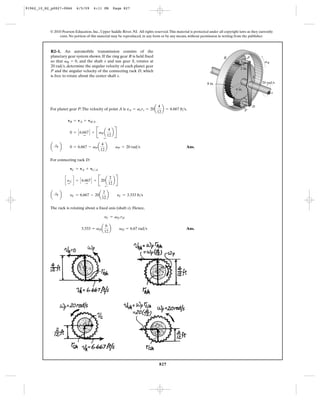
R2–1. An automobile transmission consists of the
planetary gear system shown. If the ring gear is held fixed
so that , and the shaft and sun gear , rotates at
, determine the angular velocity of each planet gear
and the angular velocity of the connecting rack , which
is free to rotate about the center shaft .s
DP
20 rad>s
SsvR = 0
R
© 2010 Pearson Education, Inc., Upper Saddle River, NJ. All rights reserved.This material is protected under all copyright laws as they currently
exist. No portion of this material may be reproduced, in any form or by any means, without permission in writing from the publisher.
P
PR
4 in.
8 in.
D
2 in.
S
20 rad/s
R
s
v
For planet gear P:The velocity of point A is .
Ans.
For connecting rack D:
The rack is rotating about a fixed axis (shaft s). Hence,
Ans.3.333 = vDa
6
12
b vD = 6.67 rad>s
yC = vD rD
a :+ b yC = 6.667 - 20a
2
12
b yC = 3.333 ft>s
c y
:
C d = C6.6
:
67D + B20 a
;
2
12
b R
vC = vA + vC>A
a :+ b 0 = 6.667 - vPa
4
12
b vP = 20 rad>s
0 = C6.6
:
67D + BvP a
;
4
12
b R
vB = vA + vB>A
yA = vsrs = 20a
4
12
b = 6.667 ft>s
91962_10_R2_p0827-0866 6/5/09 4:11 PM Page 827
- 2. 828
For planet gear P: The velocity of points A and B are
and .
Ans.
For connecting rack D:
The rack is rotating about a fixed axis (shaft s). Hence,
Ans.2.667 = vDa
6
12
b vD = 5.33 rad>s
yC = vD rD
a :+ b yC = 6.667 - 24a
2
12
b yC = 2.667 ft>s
c y
:
C d = c6.6
:
67d + B24 a
;
2
12
b R
vC = vA + vC>A
a :+ b -1.333 = 6.667 - vPa
4
12
b vP = 24 rad>s
c1.3
;
33d = c6.6
:
67d + BvP a
;
4
12
b R
vB = vA + vB>A
yB = vB rB = 2a
8
12
b = 1.333 ft>s=6.667 ft>s
yA = vS rS = 20a
4
12
b
R2–2. An automobile transmission consists of the
planetary gear system shown. If the ring gear rotates at
, and the shaft and sun gear , rotates at
, determine the angular velocity of each planet gear
and the angular velocity of the connecting rack , which
is free to rotate about the center shaft .s
DP
20 rad>s
SsvR = 2 rad>s
R
© 2010 Pearson Education, Inc., Upper Saddle River, NJ. All rights reserved.This material is protected under all copyright laws as they currently
exist. No portion of this material may be reproduced, in any form or by any means, without permission in writing from the publisher.
P
PR
4 in.
8 in.
D
2 in.
S
20 rad/s
R
s
v
91962_10_R2_p0827-0866 6/5/09 4:11 PM Page 828
- 3. 829
Datum at A:
a
Solving,
Ans.
vC = 7.61 ft>s
vBL = -35.3 ft>s
v2 = 3.81 rad>s
vC = 2v2
e = 0.7 =
vC - vBL
50 - [-5.675(2)]
1
32.2
(50)(2) - c
1
3
a
6
32.2
b(3)2
d(5.675) = c
1
3
a
6
32.2
b(3)2
dv2 +
1
32.2
(vBL)(2)
+ (HA)1 = (HA)2
v = 5.675 rad>s
0 + 0 =
1
2
c
1
3
a
6
32.2
b(3)2
dv2
- 6(1.5)
T1 + V1 = T2 + V2
R2–3. The 6-lb slender rod is released from rest when
it is in the horizontal position so that it begins to rotate
clockwise. A 1-lb ball is thrown at the rod with a velocity
. The ball strikes the rod at at the instant the
rod is in the vertical position as shown. Determine the
angular velocity of the rod just after the impact. Take
and .d = 2 fte = 0.7
Cv = 50 ft>s
AB
© 2010 Pearson Education, Inc., Upper Saddle River, NJ. All rights reserved.This material is protected under all copyright laws as they currently
exist. No portion of this material may be reproduced, in any form or by any means, without permission in writing from the publisher.
A
B
C
d
ϭ 50 ft/sv
3 ft
91962_10_R2_p0827-0866 6/5/09 4:11 PM Page 829
- 4. 830
© 2010 Pearson Education, Inc., Upper Saddle River, NJ. All rights reserved.This material is protected under all copyright laws as they currently
exist. No portion of this material may be reproduced, in any form or by any means, without permission in writing from the publisher.
A
B
C
d
ϭ 50 ft/sv
3 fta
Thus,
Ans.
vBL = -19.5 ft>s
v2 = 7.73 rad>s
vC = 2v2
e = 0.7 =
vC - vBL
50 - 0
a
1
32.2
b(50)(2) = c
1
3
a
6
32.2
b(3)2
dv2 +
1
32.2
(vBL)(2)
+ (HA)1 = (HA)2
*R2–4. The 6-lb slender rod is originally at rest,
suspended in the vertical position. A 1-lb ball is thrown at
the rod with a velocity and strikes the rod at .
Determine the angular velocity of the rod just after the
impact.Take and .d = 2 fte = 0.7
Cv = 50 ft>s
AB
91962_10_R2_p0827-0866 6/5/09 4:11 PM Page 830
- 5. 831
© 2010 Pearson Education, Inc., Upper Saddle River, NJ. All rights reserved.This material is protected under all copyright laws as they currently
exist. No portion of this material may be reproduced, in any form or by any means, without permission in writing from the publisher.
R2–5. The 6-lb slender rod is originally at rest, suspended
in the vertical position. Determine the distance where the
1-lb ball, traveling at , should strike the rod so
that it does not create a horizontal impulse at .What is the
rod’s angular velocity just after the impact? Take .e = 0.5
A
v = 50 ft>s
d A
B
C
d
ϭ 50 ft/sv
3 ftRod:
a
Thus,
Ans.
This is called the center of percussion. See Example 19–5.
a
Thus,
Ans.
vBL = -11.4 ft>s
v2 = 6.82 rad>s
vC = 2v2
e = 0.5 =
vC - vBL
50 - 0
1
32.2
(50)(2) = c
1
3
a
6
32.2
b(3)2
dv2 +
1
32.2
(vBL)(2)
+ (HA)1 = (HA)2
d = 2 ft
m(1.5v)(d - 1.5) =
1
12
(m)(3)2
v
0 +
L
F dt = m(1.5v)
m(vG)1 + ©
L
F dt = m(vG)2
0 +
L
F dt (d - 1.5) = a
1
12
(m)(3)2
bv
+ (HG)1 + ©
L
MG dt = (HG)2
91962_10_R2_p0827-0866 6/5/09 4:12 PM Page 831
- 6. 832
© 2010 Pearson Education, Inc., Upper Saddle River, NJ. All rights reserved.This material is protected under all copyright laws as they currently
exist. No portion of this material may be reproduced, in any form or by any means, without permission in writing from the publisher.
Using instantaneous center method:
Equating the i and j components yields:
Ans.
d-9.6 = -0.5a + (12.5)sin 60° a = 40.8 rad>s2
2.4 = -aA cos 60° + 8.64 aA = 12.5 m>s2
;
2.4i - 9.6j = (-aA cos 60° + 8.64)i + (-0.5a + aA sin 60°)j
2.4i - 9.6j = (-aA cos 60°i + aA sin 60°j) + (ak) * (-0.5i) - (4.157)2
(-0.5i)
aB = aA + a * rB>A - v2
rB>A
aA = -aA cos 60°i + aA sin 60°j a = ak rB>A = {-0.5i} m
aB = 16(0.15)i - 82
(0.15)j = {2.4i - 9.6j} m>s2
vAB =
yB
rB>IC
=
8(0.15)
0.5 tan 30°
= 4.157 rad>s
R2–6. At a given instant, the wheel rotates with the
angular motions shown. Determine the acceleration of the
collar at at this instant.A
A
60Њ
500 mm
B 150 mm
30Њ
ϭ 8 rad/s
ϭ 16 rad/s2a
v
91962_10_R2_p0827-0866 6/5/09 4:12 PM Page 832
- 7. 833
© 2010 Pearson Education, Inc., Upper Saddle River, NJ. All rights reserved.This material is protected under all copyright laws as they currently
exist. No portion of this material may be reproduced, in any form or by any means, without permission in writing from the publisher.
Potential Energy: Datum is set at point A. When the gear is at its final position
, its center of gravity is located ( ) below the datum. Its gravitational
potential energy at this position is . Thus, the initial and final potential
energies are
Kinetic Energy: When gear B is at its final position , the velocity of its
mass center is or since the gear rolls without slipping on the
fixed circular gear track. The mass moment of inertia of the gear about its mass
center is . Since the gear is at rest initially, the initial kinetic energy is
.The final kinetic energy is given by
Conservation of Energy: Applying Eq. 18–18, we have
Thus, the angular velocity of the radical line AB is given by
Ans.vAB =
yB
R - r
=
A
4g
3(R - r)
yB =
B
4g(R - r)
3
0 + 0 =
3
4
my2
B + [-mg(R - r)]
T1 + V1 = T2 + V2
T2 =
1
2
my2
B +
1
2
IB v2
g =
1
2
myB
2
+
1
2
a
1
2
mr2
b a
yB
r
b
2
=
3
4
my2
B
T1 = 0
IB =
1
2
mr2
vg =
yB
r
yB = vg r
(u = 90°)
V1 = 0 V2 = -mg(R - r)
-mg(R - r)
R - r(u = 90°)
R2–7. The small gear which has a mass can be treated as
a uniform disk. If it is released from rest at , and rolls
along the fixed circular gear rack, determine the angular
velocity of the radial line at the instant .u = 90°AB
u = 0°
m A
B
r
R
u
91962_10_R2_p0827-0866 6/5/09 4:12 PM Page 833
- 8. 834
© 2010 Pearson Education, Inc., Upper Saddle River, NJ. All rights reserved.This material is protected under all copyright laws as they currently
exist. No portion of this material may be reproduced, in any form or by any means, without permission in writing from the publisher.
Ans.
(a
Ans.t = 1.53 s
- c
1
2
(50)(0.2)2
d(30) + 0.2(490.5)(0.2)(t) = 0
+) IB v1 + ©
L
t2
t1
MB dt = IB v2
0 + 0.2(490.5)(t)—2FAB (t) = 0 FAB = 49.0 N
a :+ b m(yAx)1 + ©
L
t2
t1
Fx dt = m(yAx)2
0 + NC (t) - 50(9.81)(t) = 0 NC = 490.5 N
(+ c) m(yAy)1 + ©
L
t2
t1
Fy dt = m(yAy)2
*R2–8. The 50-kg cylinder has an angular velocity of
when it is brought into contact with the surface at
. If the coefficient of kinetic friction is , determine
how long it will take for the cylinder to stop spinning.What
force is developed in link during this time? The axis of
the cylinder is connected to two symmetrical links. (Only
is shown.) For the computation, neglect the weight of
the links.
AB
AB
mk = 0.2C
30 rad>s
BA
200 mm
500 mm
C
ϭ 30 rad/sv
Originally, both gears rotate with an angular velocity of .After
the rack has traveled , both gears rotate with an angular velocity of
, where is the speed of the rack at that moment.
Put datum through points A and B.
T1 + V1 = T2 + V2
y2v2 =
y2
0.05
s = 600 mm
vt =
2
0.05
= 40 rad>s
R2–9. The gear rack has a mass of 6 kg, and the gears each
have a mass of 4 kg and a radius of gyration of
about their center. If the rack is originally moving
downward at , when , determine the speed of the
rack when . The gears are free to rotate about
their centers, and .BA
s = 600 mm
s = 02 m>s
k = 30 mm
Ans.y2 = 3.46 m>s
1
2
(6)(2)2
+ b
1
2
C4(0.03)2
D(40)2
r + 0 =
1
2
(6)y2
2 + 2b
1
2
C4(0.03)2
D a
y2
0.05
b r -6(9.81)(0.6)
s
A B
50 mm50 mm
91962_10_R2_p0827-0866 6/5/09 4:12 PM Page 834
- 9. 835
© 2010 Pearson Education, Inc., Upper Saddle River, NJ. All rights reserved.This material is protected under all copyright laws as they currently
exist. No portion of this material may be reproduced, in any form or by any means, without permission in writing from the publisher.
R2–10. The gear has a mass of 2 kg and a radius of
gyration . The connecting link (slender
rod) and slider block at have a mass of 4 kg and 1 kg,
respectively. If the gear has an angular velocity
at the instant , determine the gear’s angular velocity
when .u = 0°
u = 45°
v = 8 rad>s
B
ABkA = 0.15 m
ϭ 8 rad/s
0.6 m
45Њ
B
A
0.2 m
v
u
At position 1:
At position 2:
Put datum through bar in position 2.
Ans.v2 = 13.3 rad>s
5.7067 + 16.6481 = 0.1258v2
2 + 0
T1 + V1 = T2 + V2
V1 = 2(9.81)(0.6 sin 45°) + 4(9.81)(0.3 sin 45°) = 16.6481 J V2 = 0
T2 = 0.1258 v2
2
+
1
2
c
1
12
(4)(0.6)2
d(0.2357v2)2
+
1
2
(1)(0.1414v2)2
T2 =
1
2
C(2)(0.15)2
D(v2)2
+
1
2
(2)(0.2 v2)2
+
1
2
(4)(0.1581v2)2
= 5.7067 J
T1 =
1
2
C(2)(0.15)2
D(8)2
+
1
2
(2)(1.6)2
+
1
2
(4)(0.8)2
+
1
2
c
1
12
(4)(0.6)2
d(2.6667)2
(yAB)2 = (vAB)2 rG>IC = 0.2357 v2(0.6708) = 0.1581v2
(yB)2 = (vAB)2 rB>IC = 0.2357 v2(0.6) = 0.1414v2
(vAB)2 =
(yA)2
rA>IC
=
v2 (0.2)
0.6
cos 45°
= 0.2357v2
(yAB)1 = (vAB)1 rG>IC = 2.6667(0.3) = 0.8 m>s
(vAB)1 =
(yA)1
rA>IC
=
1.6
0.6
= 2.6667 rad>s (yB)1 = 0
91962_10_R2_p0827-0866 6/5/09 4:13 PM Page 835
- 10. 836
© 2010 Pearson Education, Inc., Upper Saddle River, NJ. All rights reserved.This material is protected under all copyright laws as they currently
exist. No portion of this material may be reproduced, in any form or by any means, without permission in writing from the publisher.
Equation of Motion: The spring force is given by . The
mass moment of inertia for the clapper AB is
. Applying
Eq. 17–12, we have
Ans.a = 12.6 rad>s2
+©MA = IA a; 0.4(0.05) - 0.5(0.09) = -1.9816A10-3
B a
0.2A0.0672
B +
2
5
(0.04)A0.0062
B + 0.04A0.142
B = 1.9816A10-3
B kg # m2
(IAB)A =
1
12
(0.2)A0.1342
B +
Fsp = kx = 20(0.02) = 0.4 N
*R2–11. The operation of a doorbell requires the use of
an electromagnet, that attracts the iron clapper that is
pinned at end and consists of a 0.2-kg slender rod to
which is attached a 0.04-kg steel ball having a radius of
If the attractive force of the magnet at is 0.5 N
when the switch is on, determine the initial angular
acceleration of the clapper. The spring is originally
stretched 20 mm.
C6 mm.
A
AB
44 mm
50 mm
40 mm
A
B
C
k ϭ 20 N/m
Moment of inertia of the door about axle AB:
Ans.v = 2.45 rad>s
0 + b15(2.5)a
p
2
b - 2a
p
2
b r =
1
2
(18.6335) v2
T1 + © U1-2 = T2
IAB = 2c
1
12
a
100
32.2
b(6)2
d = 18.6335 slug # ft2
*R2–12. The revolving door consists of four doors which
are attached to an axle . Each door can be assumed to be
a 50-lb thin plate. Friction at the axle contributes a moment
of which resists the rotation of the doors. If a woman
passes through one door by always pushing with a force
perpendicular to the plane of the door as shown,
determine the door’s angular velocity after it has rotated
90°.The doors are originally at rest.
P = 15 lb
2 lb # ft
AB
A
7 ft
B
2.5 ft
3 ft
P ϭ 15 lb
u
91962_10_R2_p0827-0866 6/5/09 4:13 PM Page 836
- 11. 837
© 2010 Pearson Education, Inc., Upper Saddle River, NJ. All rights reserved.This material is protected under all copyright laws as they currently
exist. No portion of this material may be reproduced, in any form or by any means, without permission in writing from the publisher.
For the cylinder,
(1)
(c
(2)
For the dolly,
(3)
(4)
Solving Eqs. (1) to (4) yields:
Ans.
vC = 32.2 ft>s vD = 32.2 ft>s F = 0
v = 0
vD = vC - 0.5v
(+R) vD = vC + vD>C
0 + F(2) + 20 sin 30°(2) = a
20
32.2
byD
(+R) m(yDx¿)1 + ©
L
t2
t1
Fx¿ dt = m(yDx¿)2
0 + F(0.5)(2) = c
1
2
a
10
32.2
b(0.5)2
dv
+) IC v1 + ©
L
t2
t1
MC dt = IC v2
0 + 10 sin 30°(2) - F(2) = a
10
32.2
byC
(+R) m(yCx¿)1 + ©
L
t2
t1
Fx¿ dt = m(yCx¿)2
R2–13. The 10-lb cylinder rests on the 20-lb dolly. If the
system is released from rest, determine the angular velocity
of the cylinder in 2 s.The cylinder does not slip on the dolly.
Neglect the mass of the wheels on the dolly.
0.5 ft
30Њ
91962_10_R2_p0827-0866 6/5/09 4:13 PM Page 837
- 12. 838
© 2010 Pearson Education, Inc., Upper Saddle River, NJ. All rights reserved.This material is protected under all copyright laws as they currently
exist. No portion of this material may be reproduced, in any form or by any means, without permission in writing from the publisher.
R2–14. Solve Prob. R2–13 if the coefficients of static and
kinetic friction between the cylinder and the dolly are
and , respectively.m = 0.2ms = 0.3 0.5 ft
30Њ
For the cylinder,
(1)
(c
(2)
For the dolly,
(3)
(4)
Solving Eqs. (1) to (4) yields:
Ans.
Note: No friction force develops.
vC = 32.2 ft>s vD = 32.2 ft>s F = 0
v = 0
vD = vC - 0.5v
(+R) vD = vC + vD>C
0 + F(2) + 20 sin 30°(2) = a
20
32.2
byD
(+R) m(yDx¿)1 + ©
L
t2
t1
Fx¿ dt = m(yDx¿)2
0 + F(0.5)(2) = c
1
2
a
10
32.2
b(0.5)2
dv
+) IC v1 + ©
L
t2
t1
MC dt = IC v2
0 + 10 sin 30°(2) - F(2) = a
10
32.2
byC
(+R) m(yCx¿)1 + ©
L
t2
t1
Fx¿ dt = m(yCx¿)2
91962_10_R2_p0827-0866 6/5/09 4:13 PM Page 838
- 13. 839
© 2010 Pearson Education, Inc., Upper Saddle River, NJ. All rights reserved.This material is protected under all copyright laws as they currently
exist. No portion of this material may be reproduced, in any form or by any means, without permission in writing from the publisher.
For link AB,
For gear H,
Principle of Work and Energy: For the system,
Ans.vDE = 132 rad>s
+
1
2
a
0.4
32.2
b(0.25vDE)2
+
1
2
c a
0.15
32.2
b a
4.5
12
b
2
dv2
DE +
1
2
a
0.15
32.2
b(0.25vDE)2
0 + 3(2p) =
1
2
c a
0.2
32.2
b a
3
12
b
2
d a
1
2
vDEb
2
+
1
2
c a
0.4
32.2
b a
2
12
b
2
dv2
DE
T1 + ©U1-2 = T2
yB = a
1
2
vDEb
6
12
= 0.25vDE
vAB =
1
2
vDE
vDE =
yB
rB>IC
=
0.5vAB
3>12
= 2vAB
yB = vAB rAB = vAB a
6
12
b = 0.5vAB
R2–15. Gears and each have a weight of 0.4 lb and a
radius of gyration about their mass center of
Link has a weight of 0.2 lb and a radius of
gyration of ( , whereas link has a weight of
0.15 lb and a radius of gyration of ( If a
couple moment of is applied to link and
the assembly is originally at rest, determine the angular
velocity of link when link has rotated 360°. Gear
is prevented from rotating, and motion occurs in the
horizontal plane. Also, gear and link rotate together
about the same axle at .B
DEH
CABDE
ABM = 3 lb # ft
kDE)B = 4.5 in.
DEkAB)A = 3 in.
AB(kC)A = 2 in.
(kH)B =
CH E
C
D
H B AM
3 in. 3 in.
91962_10_R2_p0827-0866 6/5/09 4:14 PM Page 839
- 14. 840
© 2010 Pearson Education, Inc., Upper Saddle River, NJ. All rights reserved.This material is protected under all copyright laws as they currently
exist. No portion of this material may be reproduced, in any form or by any means, without permission in writing from the publisher.
*R2–16. The inner hub of the roller bearing rotates with
an angular velocity of , while the outer hub
rotates in the opposite direction at . Determine
the angular velocity of each of the rollers if they roll on the
hubs without slipping.
vo = 4 rad>s
vi = 6 rad>s
o
ϭ 4 rad/s
25 mm
50 mm
i
ϭ 6 rad/sv
v
Since the hub does not slip, and
.
b Ans.(+ T) 0.4 = -0.3 + 0.05v v = 14 rad>s
c0.
T
4d = c0.
c
3d + Bv(0.
T
05)R
vB = vA + vB>A
4(0.1) = 0.4 m>s
yB = vO rO =yA = vi ri = 6(0.05) = 0.3 m>s
91962_10_R2_p0827-0866 6/5/09 4:14 PM Page 840
- 15. 841
© 2010 Pearson Education, Inc., Upper Saddle River, NJ. All rights reserved.This material is protected under all copyright laws as they currently
exist. No portion of this material may be reproduced, in any form or by any means, without permission in writing from the publisher.
(a
Solving,
Ans.t = 1.32 s
vG = 2.75 m>s
-5(0.5)2
(8) + 25.487(0.5)(t) = 5(0.5)2
a
vG
0.5
b
+) (HG)1 + ©
L
MG dt = (HG)2
5(3) + 5(9.181) sin 30°(t) - 25.487t = 5vG
(b+) mvx1 + ©
L
Fx dt = mvx2
Fh = 0.6Nh = 0.6(42.479 N) = 25.487 N
Nh = 42.479 N
0 + Nh (1) - 5(9.81)t cos 30° = 0
(+a) mvy1 + ©
L
Fy dt = mvy2
R2–17. The hoop (thin ring) has a mass of 5 kg and is
released down the inclined plane such that it has a backspin
and its center has a velocity as
shown. If the coefficient of kinetic friction between the
hoop and the plane is , determine how long the
hoop rolls before it stops slipping.
mk = 0.6
vG = 3 m>sv = 8 rad>s
See solution to Prob. R2–17. Since backspin will not stop in , then
a
d Ans.v = 2.19 rad>s
-5(0.5)2
(8) + 25.487(0.5)(1) = -5(0.5)2
v
+ (HG)1 + ©
L
M dt = (HG)2
Fh = 0.6Nh = 0.6(42.479 N) = 25.487 N
Nh = 42.479 N
0 + Nh (t) - 5(9.81)t cos 30° = 0
(+a) mvy1 + ©
L
Fy dt = mvy2
t = 1 s 6 1.32 s
R2–18. The hoop (thin ring) has a mass of 5 kg and is
released down the inclined plane such that it has a backspin
and its center has a velocity as
shown. If the coefficient of kinetic friction between the
hoop and the plane is , determine the hoop’s
angular velocity 1 s after it is released.
mk = 0.6
vG = 3 m>sv = 8 rad>s
G
0.5 m
30Њ
ϭ 8 rad/s
ϭ 3 m/svG
v
G
0.5 m
30Њ
ϭ 8 rad/s
ϭ 3 m/svG
v
91962_10_R2_p0827-0866 6/5/09 4:14 PM Page 841
- 16. 842
© 2010 Pearson Education, Inc., Upper Saddle River, NJ. All rights reserved.This material is protected under all copyright laws as they currently
exist. No portion of this material may be reproduced, in any form or by any means, without permission in writing from the publisher.
Here , and .
Ans.-5 = -0.03 csc2
30°(vCD) vCD = 4.17 rad>s
u = 30°yAB = -5 m>su
#
= vCD
x
#
= yAB = -0.3 csc2
uu
#
x =
0.3
tan u
= 0.3 cot u
R2–19. Determine the angular velocity of rod at the
instant . Rod moves to the left at a constant
speed of .vAB = 5 m>s
ABu = 30°
CD
A
C
vAB
B
D
0.3 m
CD
u
v
91962_10_R2_p0827-0866 6/5/09 4:14 PM Page 842
- 17. 843
© 2010 Pearson Education, Inc., Upper Saddle River, NJ. All rights reserved.This material is protected under all copyright laws as they currently
exist. No portion of this material may be reproduced, in any form or by any means, without permission in writing from the publisher.
A
C
vAB
B
D
0.3 m
CD
u
v
Here , , , , and .
Ans.2 = 0.3 csc2
30°C2 cot 30°(0)2
- aCDD aCD = -1.67 rad>s2
0 = -0.3 csc2
30°(vCD) vCD = 0
u = 30°u
$
= aCDaAB = 2 m>s2
yAB = 0u
#
= vCD
x
$
= aAB = -0.3ccsc2
uu
$
- 2 csc2
u cot uu
# 2
d = 0.3 csc2
ua2 cot uu
# 2
- u
$
b
x
#
= yAB = -0.3 csc2
uu
#
x =
0.3
tan u
= 0.3 cot u
*R2–20. Determine the angular acceleration of rod at
the instant . Rod has zero velocity, i.e., ,
and an acceleration of to the right when
.u = 30°
aAB = 2 m>s2
vAB = 0ABu = 30°
CD
91962_10_R2_p0827-0866 6/5/09 4:15 PM Page 843
- 18. 844
R2–21. If the angular velocity of the drum is increased
uniformly from when to when
determine the magnitudes of the velocity and acceleration
of points and on the belt when . At this instant
the points are located as shown.
t = 1 sBA
t = 5 s,12 rad>st = 06 rad>s
© 2010 Pearson Education, Inc., Upper Saddle River, NJ. All rights reserved.This material is protected under all copyright laws as they currently
exist. No portion of this material may be reproduced, in any form or by any means, without permission in writing from the publisher.
45Њ
4 in.
A
B
Angular Motion: The angular acceleration of drum must be determined first.
Applying Eq. 16–5, we have
The angular velocity of the drum at is given by
Motion of P: The magnitude of the velocity of points A and B can be determined
using Eq. 16–8.
Ans.
Also,
Ans.
The tangential and normal components of the acceleration of points B can be
determined using Eqs. 16–11 and 16–12, respectively.
The magnitude of the acceleration of points B is
Ans.aB = 2(at)B
2
+ (an)B
2
= 20.4002
+ 17.282
= 17.3 ft>s2
(an)B = v2
r = A7.202
B a
4
12
b = 17.28 ft>s2
(at)B = ac r = 1.20a
4
12
b = 0.400 ft>s2
aA = (at)A = ac r = 1.20a
4
12
b = 0.400 ft>s2
yA = yB = vr = 7.20a
4
12
b = 2.40 ft>s
v = v0 + ac t = 6 + 1.20(1) = 7.20 rad>s
t = 1 s
ac = 1.20 rad>s2
12 = 6 + ac (5)
v = v0 + ac t
91962_10_R2_p0827-0866 6/5/09 4:15 PM Page 844
- 19. 845
Kinematics: Since pulley A is rotating about a fixed point B and pulley P rolls down
without slipping, the velocity of points D and E on the pulley P are given by
and where is the angular velocity of pulley A. Thus, the
instantaneous center of zero velocity can be located using similar triangles.
Thus, the velocity of block C is given by
Potential Energy: Datumn is set at point B. When block C is at its initial and final
position, its locations are 5 ft and 10 ft below the datum. Its initial and final
gravitational potential energies are and ,
respectively.Thus, the initial and final potential energy are
Kinetic Energy: The mass moment of inertia of pulley A about point B is
. Since the system is initially at rest, the
initial kinetic energy is .The final kinetic energy is given by
Conservation of Energy: Applying Eq. 18–19, we have
Thus, the speed of block C at the instant is
Ans.yC = 0.6vA = 0.6(21.15) = 12.7 ft>s
s = 10 ft
vA = 21.15 rad>s
0 + -100 = 0.2236v2
A + (-200)
T1 + V1 = T2 + V2
= 0.2236v2
A
=
1
2
a
20
32.2
b(0.6vA)2
+
1
2
(0.2236) vA
2
T2 =
1
2
mC y2
C +
1
2
IB v2
A
T1 = 0
IB = mkB
2
=
20
32.2
A0.62
B = 0.2236 slug # ft2
V1 = -100 ft # lb V2 = -200 ft # lb
20(-10) = -200 ft # lb20(-5) = -100 ft # lb
yC
0.6
=
0.4vA
0.4
yC = 0.6vA
x
0.4vA
=
x + 0.4
0.8vA
x = 0.4 ft
vAyE = 0.8vAyD = 0.4vA
R2–22. Pulley and the attached drum have a weight
of 20 lb and a radius of gyration of If pulley
“rolls” downward on the cord without slipping, determine
the speed of the 20-lb crate at the instant .
Initially, the crate is released from rest when For
the calculation, neglect the mass of pulley and the cord.P
s = 5 ft.
s = 10 ftC
PkB = 0.6 ft.
BA
© 2010 Pearson Education, Inc., Upper Saddle River, NJ. All rights reserved.This material is protected under all copyright laws as they currently
exist. No portion of this material may be reproduced, in any form or by any means, without permission in writing from the publisher.
0.8 ft
0.4 ft
0.2 ft
A
B
C
P
s
91962_10_R2_p0827-0866 6/5/09 4:15 PM Page 845
- 20. 846
Equations of Motion: The mass moment of inertia of the ring about its mass center
is given by .Applying Eq. 17–16, we have
a
Kinematics: The time required for the ring to stop back spinning can be determined
by applying Eq. 16–5.
(c
The distance traveled by the ring just before back spinning stops can be determine
by applying Eq. 12–5.
Ans.=
v1 r
2mg
(2y1 - v1r)
= 0 + y1 a
v1 r
mg
b +
1
2
(-mg)a
v1r
mg
b
2
A ;+ B s = s0 + y0 t +
1
2
ac t2
t =
v1 r
mg
0 = v1 + a -
mg
r
bt+)
v = v0 + ac t
+©MG = IG a; mmgr = mr2
a a =
mg
r
:+ ©Fx = m(aG)x ; mmg = maG aG = mg
+ c©Fy = m(aG)y ; N - mg = 0 N = mg
IG = mr2
R2–23. By pressing down with the finger at , a thin ring
having a mass is given an initial velocity and a
backspin when the finger is released. If the coefficient of
kinetic friction between the table and the ring is ,
determine the distance the ring travels forward before the
backspin stops.
m
v1
v1m
B
© 2010 Pearson Education, Inc., Upper Saddle River, NJ. All rights reserved.This material is protected under all copyright laws as they currently
exist. No portion of this material may be reproduced, in any form or by any means, without permission in writing from the publisher.
B
1
1
v
r
A
v
91962_10_R2_p0827-0866 6/5/09 4:15 PM Page 846
- 21. 847
The wheels roll without slipping, hence .v =
yG
r
*R2–24. The pavement roller is traveling down the incline
at when the motor is disengaged. Determine the
speed of the roller when it has traveled 20 ft down the
plane. The body of the roller, excluding the rollers, has a
weight of 8000 lb and a center of gravity at . Each of the
two rear rollers weighs 400 lb and has a radius of gyration of
The front roller has a weight of 800 lb and a
radius of gyration of The rollers do not slip as
they turn.
kB = 1.8 ft.
kA = 3.3 ft.
G
v1 = 5 ft>s
© 2010 Pearson Education, Inc., Upper Saddle River, NJ. All rights reserved.This material is protected under all copyright laws as they currently
exist. No portion of this material may be reproduced, in any form or by any means, without permission in writing from the publisher.
= 166.753 y2
T2 =
1
2
a
8000 + 800 + 800
32.2
by2
+
1
2
c a
800
32.2
b(3.3)2
d a
y
3.8
b
2
+
1
2
c a
800
32.2
b(1.8)2
d a
y
2.2
b
2
= 4168.81 ft # lb
T1 =
1
2
a
8000 + 800 + 800
32.2
b(5)2
+
1
2
c a
800
32.2
b(3.3)2
d a
5
3.8
b
2
+
1
2
c a
800
32.2
b(1.8)2
d a
5
2.2
b
2
Put datum through the mass center of the wheels and body of the roller when it is in
the initial position.
Ans.y = 24.5 ft>s
4168.81 + 0 = 166.753y2
- 96000
T1 + V1 = T2 + V2
= -96000 ft # lb
V2 = -800(20 sin 30°) - 8000(20 sin 30°) - 800(20 sin 30°)
V1 = 0
Ans.vB =
2
0.3
= 6.67 rad>s
vD = 5(0.4) = 2 m>s
R2–25. The cylinder rolls on the fixed cylinder without
slipping. If bar rotates with an angular velocity
, determine the angular velocity of cylinder .
Point is a fixed point.C
BvCD = 5 rad>s
CD
AB
B
G
4.5 ft
2.2 ft
5 ft
10 ft
30Њ
A
3.8 ft
A
B
C
D
0.1 m 0.3 m
CD ϭ 5 rad/sv
91962_10_R2_p0827-0866 6/5/09 4:16 PM Page 847
- 22. 848
c
Ans.
The displacement , hence
Ans.h =
mg
M + 2m
t2
h
R
= 0 + 0 +
1
2
a
2mg
R(M + 2m)
bt2
u - u0 + v0 t +
1
2
ac t2
u =
h
R
h = Ru
a =
2mg
R(M + 2m)
+©MO = ©tMk)0; mgR =
1
2
MR2
(a) + m(aR)R
I0 =
1
2
MR2
R2–26. The disk has a mass and a radius . If a block of
mass is attached to the cord, determine the angular
acceleration of the disk when the block is released from
rest. Also, what is the distance the block falls from rest in
the time ?t
m
RM
© 2010 Pearson Education, Inc., Upper Saddle River, NJ. All rights reserved.This material is protected under all copyright laws as they currently
exist. No portion of this material may be reproduced, in any form or by any means, without permission in writing from the publisher.
R
91962_10_R2_p0827-0866 6/5/09 4:16 PM Page 848
- 23. 849
© 2010 Pearson Education, Inc., Upper Saddle River, NJ. All rights reserved.This material is protected under all copyright laws as they currently
exist. No portion of this material may be reproduced, in any form or by any means, without permission in writing from the publisher.
G
0.8 ft
M
u
G
0.8 ft
M
u
Ans.v = 3.89 rad>s
0 + 60a
p
2
b - 70(0.8) =
1
2
c a
70
32.2
b(1.3)2
d(v)2
+
1
2
c
70
32.2
d(0.8v)2
T1 + ©U1-2 = T2
R2–27. The tub of the mixer has a weight of 70 lb and a
radius of gyration about its center of gravity .
If a constant torque is applied to the dumping
wheel, determine the angular velocity of the tub when it has
rotated . Originally the tub is at rest when .
Neglect the mass of the wheel.
u = 0°u = 90°
M = 60 lb # ft
GkG = 1.3 ft
Ans.v = 1.50 rad>s
0 +
L
p>2
0
50u du - 70(0.8) =
1
2
c a
70
32.2
b(1.3)2
dv2
+
1
2
c
70
32.2
d(0.8v)2
T1 + ©U1-2 = T2
*R2–28. Solve Prob. R2–27 if the applied torque is
, where is in radians.uM = (50u) lb # ft
91962_10_R2_p0827-0866 6/5/09 4:16 PM Page 849
- 24. 850
© 2010 Pearson Education, Inc., Upper Saddle River, NJ. All rights reserved.This material is protected under all copyright laws as they currently
exist. No portion of this material may be reproduced, in any form or by any means, without permission in writing from the publisher.
R2–29. The spool has a weight of 30 lb and a radius of
gyration A cord is wrapped around the spool’s
inner hub and its end subjected to a horizontal force
. Determine the spool’s angular velocity in 4 s
starting from rest.Assume the spool rolls without slipping.
P = 5 lb
kO = 0.45 ft.
a
[1]
Since the seesaw is rotating about point A, then
[2]
Solving Eqs. (1) and (2) yields:
Ans.am = 1.45 m>s2
ab = 1.94 m>s2
a =
ab
2
=
am
1.5
or am = 0.75ab
= -40ab (2) - 75am (1.5)
+©MA = ©(Mk)A ; 40(9.81)(2) - 75(9.81)(1.5)
R2–30. The 75-kg man and 40-kg boy sit on the horizontal
seesaw, which has negligible mass. At the instant the man
lifts his feet from the ground, determine their accelerations
if each sits upright, i.e., they do not rotate. The centers of
mass of the man and boy are at and , respectively.GbGm
P ϭ 5 lb
0.9 ft
0.3 ft
A
O
2 m 1.5 m
A
Gb Gm
b)
Ans.v2 = 12.7 rad>s
0 + 5(0.6)(4) = c a
30
32.2
b(0.45)2
+ a
30
32.2
b(0.9)2
dv2
IA v1 + ©
L
t2
t1
MA dt = IAv2(+
91962_10_R2_p0827-0866 6/5/09 4:16 PM Page 850
- 25. 851
© 2010 Pearson Education, Inc., Upper Saddle River, NJ. All rights reserved.This material is protected under all copyright laws as they currently
exist. No portion of this material may be reproduced, in any form or by any means, without permission in writing from the publisher.
Principle of Impulse and Momentum: For the sphere,
a)
Ans.
Principle of Impulse and Momentum: For the cyclinder,
a)
Ans.(vC)2 =
2g sin u
3r
t
0 + mg sin u(r)(t) = c
1
2
mr2
+ mr2
d(vC)2
IA v1 + ©
L
t2
t1
MA dt = IAv2(+
(vS)2 =
5g sin u
7r
t
0 + mg sin u(r)(t) = c
2
5
mr2
+ mr2
d(vS)2
IA v1 + ©
L
t2
t1
MA dt = IAv2(+
R2–31. A sphere and cylinder are released from rest on
the ramp at . If each has a mass and a radius ,
determine their angular velocities at time . Assume no
slipping occurs.
t
rmt = 0
u
91962_10_R2_p0827-0866 6/5/09 4:17 PM Page 851
- 26. 852
© 2010 Pearson Education, Inc., Upper Saddle River, NJ. All rights reserved.This material is protected under all copyright laws as they currently
exist. No portion of this material may be reproduced, in any form or by any means, without permission in writing from the publisher.
*R2–32. At a given instant, link has an angular
acceleration and an angular velocity
. Determine the angular velocity and angular
acceleration of link at this instant.CD
vAB = 4 rad>s
aAB = 12 rad>s2
AB
Ans.
d Ans.aCD =
155
1.5
= 103 rad>s2
(aC)t = 155 ft>s2
aBC = 54.4 rad>s2
(+ T) 44.44 sin 60° + (aC)t sin 30° = -30 sin 45° + 40 sin 45° + 2aBC
( ;+ ) -44.44 cos 60° + (aC)t cos 30° = 30 cos 45° + 40 cos 45° + 62.21
C
44.44
c60°
S + C
(aC)t
30°d
S = C
30
45°b
S + C
40
45°d
S + c2(5.5
;
8)2
d + B
2aBC
T
R
aC = aB + aC>B
vCD =
8.16
1.5
= 5.44 rad>s
vC = 8.16 ft>s
vBC = 5.58 rad>s
(+ T) vC sin 30° = - 10 sin 45° + 2vBC
( ;+ ) vC cos 30° = 10 cos 45° + 0
C
nC
30°d
S = C
10
45°b
S + B
2vBC
T
R
vC = vB + vC>B
B 2 ft
45Њ
60Њ2.5 ft
1.5 ft
C
D
A
CD
AB
AB
CDa
a
v
v
91962_10_R2_p0827-0866 6/5/09 4:17 PM Page 852
- 27. 853
R2–33. At a given instant, link has an angular
acceleration and an angular velocity
. Determine the angular velocity and angular
acceleration of link at this instant.AB
vCD = 2 rad>s
aCD = 5 rad>s2
CD
© 2010 Pearson Education, Inc., Upper Saddle River, NJ. All rights reserved.This material is protected under all copyright laws as they currently
exist. No portion of this material may be reproduced, in any form or by any means, without permission in writing from the publisher.
d Ans.
b Ans.aAB =
12.332
2.5
= 4.93 rad>s2
a = 1.80 rad>s2
(aB)t = -12.332 ft>s2
-3.818 + (aB)t(0.7071) = -5.1962 - 3.75 - 2a
-3.818 - (aB)t(0.7071) = 3 - 6.495 + 8.3971
-7.5 cos 30°i - 7.5 sin 30°j + (ak) * (-2i) - (2.0490)2
(-2i)
-5.400 cos 45°i - 5.400 sin 45°j - (aB)t cos 45°i + (aB)t sin 45°j = 6 sin 30°i - 6 cos 30°j
aB = aC + a * rB>C - v2
rB>C
(aC)t = aCD(rCD) = 5(1.5) = 7.5 ft>s2
(aC)n =
vC
2
rCD
=
(3)2
1.5
= 6 ft>s2
(aB)n =
v2
B
rBA
=
(3.6742)2
2.5
= 5.4000 ft>s2
vAB =
3.6742
2.5
= 1.47 rad>s
vB = 2.0490(1.793) = 3.6742 ft>s
vBC =
3
1.464
= 2.0490 rad>s
rIC-B
sin 60°
=
2
sin 75°
rIC-B = 1.793 ft
rIC-C
sin 45°
=
2
sin 75°
rIC-C = 1.464 ft
B 2 ft
45Њ
60Њ2.5 ft
1.5 ft
C
D
A
CD
AB
AB
CDa
a
v
v
91962_10_R2_p0827-0866 6/5/09 4:18 PM Page 853
- 28. 854
© 2010 Pearson Education, Inc., Upper Saddle River, NJ. All rights reserved.This material is protected under all copyright laws as they currently
exist. No portion of this material may be reproduced, in any form or by any means, without permission in writing from the publisher.
(1)
(2)
c (3)
The spool does not slip at point A, therefore
(4)
Solving Eqs. (1) to (4) yields:
b Ans.a = 2.66 rad>s2
NB = 346.8 N T = 281.5 N aG = 0.2659 m>s2
aG = 0.1a
+©MG = IG a; T(0.1) - 0.15NB(0.4) = 2.76125a
+ a©Fy¿ = m(aG)y¿ ; NB - 50(9.81) cos 45° = 0
+b©Fx¿ = m(aG)x¿ ; 50(9.81) sin 45° - T - 0.15NB = 50aG
IG = mk2
G = 500(0.235)2
= 2.76125 kg # m2
R2–34. The spool and the wire wrapped around its core
have a mass of 50 kg and a centroidal radius of gyration of
. If the coefficient of kinetic friction at the
surface is , determine the angular acceleration of
the spool after it is released from rest.
mk = 0.15
kG = 235 mm
0.1 m
B
0.4 m
45Њ
G
91962_10_R2_p0827-0866 6/5/09 4:18 PM Page 854
- 29. 855
© 2010 Pearson Education, Inc., Upper Saddle River, NJ. All rights reserved.This material is protected under all copyright laws as they currently
exist. No portion of this material may be reproduced, in any form or by any means, without permission in writing from the publisher.
(1)
(2)
Combine Eqs. (1) and (2):
Ans.
From Eq. (1),
Ans.vB = sB = 5.774 cos 45°(1.076) = 4.39 ft>s
v = u = 1.08 rad>s
-3.536u
#
= -6 + 2.041u
#
-5 sin u u
#
= -6 + 5.774 cos u(u
#
)(sin 30°)
-5 sin u u
$
= s
#
A + s
#
B sin 30°
5 cos u = sA + sB sin 30°
s
$
B = 5.774 cos uu
#
s
#
B = 5.774 sin u
sB cos 30° = 5 sin u
R2–35. The bar is confined to move along the vertical and
inclined planes. If the velocity of the roller at is
when , determine the bar’s angular
velocity and the velocity of at this instant.B
u = 45°vA = 6 ft>s
A
See solution to Prob. R2–35.
Taking the time derivatives of Eqs. (1) and (2) yields:
Substitute the data:
Solving:
Ans.
Ans.aB = -5.99 ft>s2
u
#
= -0.310 rad>s2
aB = -8.185 - 7.071 u
$
aB = -4.726 + 4.083 u
$
-5 cos 45°(1.076)2
- 5 sin 45°(u
$
) = 0 + aB sin 30°
aB = -5.774 sin 45°(1.076)2
+ 5.774 cos 45°(u
$
)
-5 cos u u
# 2
- 5 sin u(u
$
) = s
$
A + s
$
B sin 30°
aB = s
$
B = -5.774 sin u(u
#
)2
+ 5.774 cos u(u
$
)
*R2–36. The bar is confined to move along the vertical
and inclined planes. If the roller at has a constant velocity
of , determine the bar’s angular acceleration and
the acceleration of when .u = 45°B
vA = 6 ft>s
A
A
B
5 ft
30Њ
vB
vA
u
A
B
5 ft
30Њ
vB
vA
u
91962_10_R2_p0827-0866 6/5/09 4:18 PM Page 855
- 30. 856
© 2010 Pearson Education, Inc., Upper Saddle River, NJ. All rights reserved.This material is protected under all copyright laws as they currently
exist. No portion of this material may be reproduced, in any form or by any means, without permission in writing from the publisher.
Equations of Motion: By considering the entire beam [FBD(a)], we have
From the FBD(b) (beam segment),
a
Ans.
Ans.
Ans.V = 0
+ c©Fy = m(aG)y ; 59166.86 sin 60° - 4000(9.81) - V = 4000(3)
N = -29583.43 N = -29.6 kN
:+ ©Fx = m(aG)x ; 59166.86 cos 60° + N = 0
M = 51240 N # m = 51.2 kN # m
-59166.86 sin 60°(2) = -4000(3)(1)
+©MO = ©(Mk)O ; M + 4000(9.81)(1)
T = 59166.86 N
+ c©Fy = may ; 2T sin 60° - 8000(9.81) = 8000(3)
R2–37. The uniform girder has a mass of 8 Mg.
Determine the internal axial force, shear, and bending
moment at the center of the girder if a crane gives it an
upward acceleration of .3 m>s2
AB
C
A B
3 m/s2
4 m60Њ 60Њ
91962_10_R2_p0827-0866 6/5/09 4:19 PM Page 856
- 31. 857
© 2010 Pearson Education, Inc., Upper Saddle River, NJ. All rights reserved.This material is protected under all copyright laws as they currently
exist. No portion of this material may be reproduced, in any form or by any means, without permission in writing from the publisher.
Conservation of Momentum:
c
Ans.v = 0.0708 rad>s
+ c
1
2
a
3
32.2
b(0.5)2
dv + a
3
32.2
b(3v)(3)
c
1
2
a
3
32.2
b(0.5)2
d(8) + 0 = c
1
3
a
5
32.2
b(3)2
dv
+©(HB)1 = ©(HB)2
R2–39. The 5-lb rod supports the 3-lb disk at its end .
If the disk is given an angular velocity while
the rod is held stationary and then released, determine the
angular velocity of the rod after the disk has stopped
spinning relative to the rod due to frictional resistance at the
bearing . Motion is in the horizontal plane. Neglect friction
at the fixed bearing .B
A
vD = 8 rad>s
AAB
A
B
3 ft
0.5 ft
D
v
Consider the system of both gears and the links.
The spring stretches .
Ans.
Note that work is done by the tangential force between the gears since each move.
For the system, though, this force is equal but opposite and the work cancels.
v = 30.7 rad>s
0 + b20a
p
4
b -
1
2
(200)(0.2828)2
r = 2b
1
2
C(2)(0.05)2
+ (2)(0.04)2
Dv2
r
T1 + ©U1-2 = T2
s = 2(0.2 sin 45°) = 0.2828 m
R2–38. Each gear has a mass of 2 kg and a radius of gyration
about its pinned mass centers and of .
Each link has a mass of 2 kg and a radius of gyration about
its pinned ends and of . If originally the
spring is unstretched when the couple moment
is applied to link , determine the angular
velocities of the links at the instant link rotates
Each gear and link is connected together and rotates in the
horizontal plane about the fixed pins and .BA
u = 45°.AC
ACM = 20 N # m
kl = 50 mmBA
kg = 40 mmBA
200 mm
k ϭ 200 N/m
50 mm
50 mm
A
M
C
DB
91962_10_R2_p0827-0866 6/5/09 4:19 PM Page 857
- 32. 858
© 2010 Pearson Education, Inc., Upper Saddle River, NJ. All rights reserved.This material is protected under all copyright laws as they currently
exist. No portion of this material may be reproduced, in any form or by any means, without permission in writing from the publisher.
*R2–40. A cord is wrapped around the rim of each 10-lb
disk. If disk is released from rest, determine the angular
velocity of disk in 2 s. Neglect the mass of the cord.A
B
B
0.5 ft
0.5 ft
A O
Principle of Impulse and Momentum: The mass moment inertia of disk A about
point O is . Applying Eq. 19–14 to disk A
[FBD(a)], we have
(1)
The mass moment inertia of disk B about its mass center is
.Applying Eq. 19–14 to disk B [FBD(b)], we have
(2)
(a (3)
Kinematics: The speed of point C on disk B is . Here,
which is directed vertically upward. Applying Eq. 16–15,
we have
(4)
Solving Eqs. (1), (2), (3), and (4) yields:
Ans.
vB = 51.52 rad>s yG = 51.52 ft>s T = 2.00 lb
vA = 51.5 rad>s
(+ c) -0.5vA = -yG + 0.5vB
C0.5v
T
A S = By
T
GR + C0.5v
c
B S
vC = vG + vC>G
yC>G = vB rC>G = 0.5vB
yC = vA rA = 0.5vA
+) 0 - [T(2)](0.5) = -0.03882vB
IG v1 + ©
L
t2
t1
MG dt = IG v2
(+ c) 0 + T(2) - 10(2) = - a
10
32.2
byG
mAyGy
B1 + ©
L
t2
t1
Fy dt = mAyGy
B1
0.03882 slug # ft2
IG =
1
2
a
10
32.2
b A0.52
B =
( +) 0 - [T(2)](0.5) = -0.03882vA
IO v1 + ©
L
t2
t1
MO dt = IO v2
IO =
1
2
a
10
32.2
b A0.52
B = 0.03882 slug # ft2
91962_10_R2_p0827-0866 6/5/09 4:19 PM Page 858
- 33. 859
© 2010 Pearson Education, Inc., Upper Saddle River, NJ. All rights reserved.This material is protected under all copyright laws as they currently
exist. No portion of this material may be reproduced, in any form or by any means, without permission in writing from the publisher.
R2–41. A cord is wrapped around the rim of each 10-lb
disk. If disk is released from rest, determine how much
time is required before attains an angular velocity
.vA = 5 rad>s
At
B
B
0.5 ft
0.5 ft
A O
Principle of Impulse and Momentum: The mass moment inertia of disk A about
point O is . Applying Eq. 19–14 to disk A
[FBD(a)], we have
(1)
The mass moment inertia of disk B about its mass center is
. Applying Eq. 19–14 to disk B [FBD(b)],
we have
(2)
(a (3)
Kinematics: The speed of point C on disk B is .
Here, which is directed vertically upward. Applying Eq.
16–15, we have
[4]
Solving Eqs. (1), (2), (3), and (4) yields:
Ans.
vB = 5.00 rad>s yG = 5.00 ft>s T = 2.00 lb
t = 0.194 s
(+ c) -2.50 = -yG + 0.5vB
B2.5
T
0R = By
T
GR + C0.5v
c
B S
vC = vG + vC>G
yC>G = vB rC>G = 0.5vB
yC = vA rA = 0.5(5) = 2.50 ft>s
+) 0 - [T(t)](0.5) = -0.03882vB
IG v1 + ©
L
t2
t1
MG dt = IG v2
(+ c) 0 + T(t) - 10(t) = - a
10
32.2
byG
mAyGy
B1 + ©
L
t2
t1
Fy dt = mAyGy
B1
A0.52
B = 0.03882 slug # ft2
IG =
1
2
a
10
32.2
b
( +) 0 - [T(t)](0.5) = -0.03882(5)
IO v1 + ©
L
t2
t1
MO dt = IO v2
IO =
1
2
a
10
32.2
b A0.52
B = 0.03882 slug # ft2
91962_10_R2_p0827-0866 6/5/09 4:20 PM Page 859
- 34. 860
© 2010 Pearson Education, Inc., Upper Saddle River, NJ. All rights reserved.This material is protected under all copyright laws as they currently
exist. No portion of this material may be reproduced, in any form or by any means, without permission in writing from the publisher.
a
Ans.
Note that the calculation neglects the small mass of the bullet after it becomes
embedded in the plate, since its position in the plate is not specified.
u = 4.45°
1
2
c
1
2
(15)(0.15)2
+ 15(0.15)2
d (0.5132)2
+ 0 = 0 + 15(9.81)(0.15)(1 - cos u)
T1 + V1 = T2 + V2
v = 0.5132 rad>s
0.01(200 cos 30°)(0.15) = c C
1
2
(15)(0.15)2
+ 15(0.15)2
d v
+(HO)1 = (HO)2
R2–42. The 15-kg disk is pinned at and is initially at rest.
If a 10-g bullet is fired into the disk with a velocity of
, as shown, determine the maximum angle to which
the disk swings.The bullet becomes embedded in the disk.
u200 m>s
O
0.15 m
30Њ
200 m/s
O
u
91962_10_R2_p0827-0866 6/5/09 4:20 PM Page 860
- 35. 861
© 2010 Pearson Education, Inc., Upper Saddle River, NJ. All rights reserved.This material is protected under all copyright laws as they currently
exist. No portion of this material may be reproduced, in any form or by any means, without permission in writing from the publisher.
Ans.
Ans.
d Ans.u = tan-1
¢
(aB)y
(aB)x
≤ = tan-1
a
32.2
24
b = 53.3°
aB = 2(aB)2
x + (aB)2
y = 2242
+ 32.22
= 40.2 ft>s2
A + c B (aB)y = -32.2 ft>s2
= 32.2 ft>s2
T
a :+ b (aB)x = -(4)2
(1.5) = -24 ft>s2
= 24 ft>s2
;
c( a
:
B)x d + B(a
c
B)yR = c32
T
.2d + 0 + c(4)2
(
;
1.5)d
aB = aG + (aB>G)t + (aB>G)n
aA = (aA)y = 56.2 ft>s2
T
(+ c) (aA)y = -32.2 - (4)2
(1.5) = -56.2 ft>s2
= 56.2 ft>s2
T
a :+ b (aA)x = 0
B( a
:
A)xR + C (a
c
A)y S = c32
T
.2d + 0 + B(4)2
(
T
1.5)R
aA = aG + (aA>G)t + (aA>G)n
R2–43. The disk rotates at a constant rate of as it
falls freely so that its center has an acceleration of
.Determine the accelerations of points and on
the rim of the disk at the instant shown.
BA32.2 ft>s2
G
4 rad>s
B
A
1.5 ft
ϭ 4 rad/s
G
v
91962_10_R2_p0827-0866 6/5/09 4:21 PM Page 861
- 36. 862
© 2010 Pearson Education, Inc., Upper Saddle River, NJ. All rights reserved.This material is protected under all copyright laws as they currently
exist. No portion of this material may be reproduced, in any form or by any means, without permission in writing from the publisher.
Ans.vH =
rE
rF
vE =
70
60
(108) = 126 rad>s
vE = vD =
rC
rD
vC =
30
50
(180) = 108 rad>s
vC = vB =
rA
rB
vG =
90
30
(60) = 180 rad>s
*R2–44. The operation of “reverse” for a three-speed
automotive transmission is illustrated schematically in the
figure. If the shaft is turning with an angular velocity of
, determine the angular velocity of the drive
shaft . Each of the gears rotates about a fixed axis. Note
that gears and , and , and are in mesh. The
radius of each of these gears is reported in the figure.
FEDCBA
H
vG = 60 rad>s
G
E
H
F C
D
B
A
G
G
ϭ 60 rad/s
H
rA
ϭ 90 mm
rB
ϭ rC
ϭ 30 mm
rD
ϭ 50 mm
rE
ϭ 70 mm
rF
ϭ 60 mm
v
v
For shaft S,
For connection D,
Ans.
Ans.uD =
rS
rD
uS =
60
150
(10.472) = 4.19 rad = 0.667 rev
aD =
rS
rD
aS =
60
150
(5.236) = 2.09 rad>s2
uS = 0 + 0 +
1
2
(5.236)(2)2
= 10.472 rad
u = u0 + v0 t+
1
2
ac t2
100(2p)
60
= 0 + aS (2) aS = 5.236 rad>s2
v = v0 + ac t
R2–45. Shown is the internal gearing of a “spinner” used
for drilling wells. With constant angular acceleration, the
motor rotates the shaft to in
starting from rest. Determine the angular acceleration of
the drill-pipe connection and the number of revolutions
it makes during the 2-s startup.
D
t = 2 s100 rev>minSM
60 mm
150 mm
D
M
S
91962_10_R2_p0827-0866 6/5/09 4:21 PM Page 862
- 37. 863
© 2010 Pearson Education, Inc., Upper Saddle River, NJ. All rights reserved.This material is protected under all copyright laws as they currently
exist. No portion of this material may be reproduced, in any form or by any means, without permission in writing from the publisher.
Kinematics: The velocity of the mass center of gear A is , and since is
rolls without slipping on the fixed circular gear track, the location of the
instantaneous center of zero velocity is as shown.Thus,
The velocity of the mass center of gear B is . The location of the
instantaneous center of zero velocity is as shown.Thus,
Potential Energy: Datum is set at point C.When gears A, B and link AC are at their
initial position , their centers of gravity are located 0.25 m, 0.125 m, and
0.125 m above the datum, respectively.The total gravitational potential energy when
they are at these positions is
.Thus, the initial and final potential energy is
Kinetic Energy: The mass moment of inertia of gears A and B about their mass center
is and .
The mass moment of inertia of link CD about point C is
. Since the system is at rest initially, the initial kinetic
energy is .The final kinetic energy is given by
Conservation of Energy: Applying Eq. 18–19, we have
Ans.vCD = 6.33 rad>s
0 + 2.636 = 0.06577 v2
CD
T1 + V1 = T2 + V2
= 0.06577 vCD
2
+
1
2
C2.42A10-3
B D(5 vCD)2
+
1
2
C7.292A10-3
B D AvCD
2
B
=
1
2
(0.5)(0.25 vCD)2
+
1
2
C0.8A10-3
B D(5vCD)2
+
1
2
(0.8)(0.125 vCD)2
T2 =
1
2
mA yD
2
+
1
2
ID vA
2
+
1
2
mB yF
2
+
1
2
IFvB
2
+
1
2
(ICD)C vCD
2
T1 = 0
0.35A0.1252
B = 7.292A10-3
B kg # m2
(ICD)C =
1
12
(0.35)A0.252
B +
IF = 0.8A0.0552
B = 2.42A10-3
B kg # m2
ID = 0.5A0.042
B = 0.8A10-3
B kg # m2
V1 = 2.636 N # m V2 = 0
= 2.636 N # m
0.5(9.81)(0.25) + 0.8(9.81)(0.125) + 0.35(9.81)(0.125)
(u = 0°)
vB =
yE
rE>(IC)1
=
0.5 vCD
0.1
= 5vCD
yF = 0.125vCD
vA =
yD
rD>IC
=
0.25 vCD
0.05
= 5vCD yE = vA rE>IC = 5vCD (0.1) = 0.5 vCD
yD = 0.25 vCD
R2–46. Gear has a mass of 0.5 kg and a radius of
gyration of , and gear has a mass of 0.8 kg
and a radius of gyration of . The link is pinned
at and has a mass of 0.35 kg. If the link can be treated as a
slender rod, determine the angular velocity of the link after
the assembly is released from rest when and falls to
.u = 90°
u = 0°
C
kB = 55 mm
BkA = 40 mm
A
C
125 mm
50 mm
75 mm
A
B
125 mm
u
91962_10_R2_p0827-0866 6/5/09 4:22 PM Page 863
- 38. 864
© 2010 Pearson Education, Inc., Upper Saddle River, NJ. All rights reserved.This material is protected under all copyright laws as they currently
exist. No portion of this material may be reproduced, in any form or by any means, without permission in writing from the publisher.
R2–47. The 15-kg cylinder rotates with an angular
velocity of . If a force is applied to
bar , as shown, determine the time needed to stop the
rotation.The coefficient of kinetic friction between and
the cylinder is . Neglect the thickness of the bar.mk = 0.4
AB
AB
F = 6 Nv = 40 rad>s
400 mm 500 mm
A B
F ϭ 6 N
C
150 mm
v
For link AB,
a
a
a
Ans.t = 10.4 s
0 = 40 + (-3.84) t
+v = v0 + at
+©MC = IC a; -0.4(10.8)(0.15) = 0.16875(a) a = -3.84 rad>s2
IC =
1
2
mr2
=
1
2
(15)(0.15)2
= 0.16875 kg # m2
+©MB = 0; 6(0.9) - NE(0.5) = 0 NE = 10.8 N
Link AB rotates about the fixed point A. Hence,
For link BC,
Ans.
Link CD rotates about the fixed point D. Hence,
Ans.0.8660 = vCD (0.4) vCD = 2.17 rad>s
yC = vCD rCD
yC = vBC rC>IC = 5.77(0.15) = 0.8660 m>s
vBC =
yB
rB>IC
=
1.5
0.2598
= 5.77 rad>s
rB>IC = 0.3 cos 30° = 0.2598 m rC>IC = 0.3 cos 60° = 0.15 m
yB = vAB rAB = 6(0.25) = 1.5 m>s
*R2–48. If link rotates at , determine
the angular velocities of links and at the instant
shown.
CDBC
vAB = 6 rad>sAB
AB ϭ 6 rad/s
A
B C
D
60Њ
30Њ
400 mm
300 mm
250 mm
v
91962_10_R2_p0827-0866 6/5/09 4:22 PM Page 864
- 39. 865
© 2010 Pearson Education, Inc., Upper Saddle River, NJ. All rights reserved.This material is protected under all copyright laws as they currently
exist. No portion of this material may be reproduced, in any form or by any means, without permission in writing from the publisher.
Equations of Motion: The mass moment of inertia of the hoop about its mass center
is given by .Applying Eq. 17–16, we have
c
Kinematics: The time required for the hoop to stop back spinning can be
determined by applying Eq. 16–5.
(c
The time required for the hoop to stop can be determined by applying Eq. 12–4.
It is required that .Thus,
Ans.v =
yG
r
vr
mg
=
yG
mg
t1 = t2
t2 =
yG
mg
0 = yG + (-mg) t2
A ;+ B y = y0 + at2
t1 =
vr
mg
+) 0 = v + a -
mg
r
b t1
v = v0 + a t1
+©MG = IG a; mWr =
W
g
r2
a a =
mg
r
:+ ©Fx = m (aG)x ; mW =
W
g
aG aG = mg
+ c©Fy = m(aG)y ; N - W = 0 N = W
IG = mr2
=
W
g
r2
R2–49. If the thin hoop has a weight and radius and is
thrown onto a rough surface with a velocity parallel to
the surface, determine the backspin, , it must be given so
that it stops spinning at the same instant that its forward
velocity is zero. It is not necessary to know the coefficient of
kinetic friction at for the calculation.A
V
vG
rW
G
Gv
r
A
v
91962_10_R2_p0827-0866 6/5/09 4:23 PM Page 865
- 40. 866
Equations of Motion: Since the tire rolls down the plane without slipping, then
.The mass moment of inertia of the tire about its mass center is given
by .Applying Eq. 17–16 to [FBD(a)], we have
(1)
a (2)
Solving Eqs. [1] and [2] yields
Equations of Equilibrium: From FBD(b).
a
Ans.
Ans.
Ans.Ax = 1.63 N
:+ ©Fx = 0; Ax + 424.79 sin 30° - 75.46 cos 30° - 297.35 sin 30° = 0
Ay = 344 N
- 424.79 cos 30° - 75.46 sin 30° = 0
+ c©Fy = 0; Ay + 297.35 cos 30° - 20(9.81)
NB = 297.35 N = 297 N
+©MA = 0; NB (4) - 20(9.81) cos 30°(2) - 424.79(2) = 0
Ff = 75.46 N a = 5.660 rad>s2
+©MG = IG a; Ff(0.6) = 8.00a
b+©Fx¿ = m(aG)x¿ ; 50(9.81) sin 30° - Ff = 50(0.6a)
a+©Fy¿ = m(aG)y¿ ; N - 50(9.81) cos 30° = 0 N = 424.79 N
IG = mkG
2
= 50A0.42
B = 8.00 kg # m2
aG = ar = 0.6a
R2–50. The wheel has a mass of 50 kg and a radius of
gyration . If it rolls without slipping down the
inclined plank, determine the horizontal and vertical
components of reaction at , and the normal reaction at the
smooth support at the instant the wheel is located at the
midpoint of the plank. The plank has negligible thickness
and has a mass of 20 kg.
B
A
kG = 0.4 m
© 2010 Pearson Education, Inc., Upper Saddle River, NJ. All rights reserved.This material is protected under all copyright laws as they currently
exist. No portion of this material may be reproduced, in any form or by any means, without permission in writing from the publisher.
30Њ
2 m
2 m
A
B
0.6 m
G
91962_10_R2_p0827-0866 6/5/09 4:23 PM Page 866