More Related Content
Similar to Chapter16 140816162809-phpapp01
Similar to Chapter16 140816162809-phpapp01 (20)
Chapter16 140816162809-phpapp01
- 1. 513
Ans.
Ans.a = 282
+ (0.5)2
= 8.02 ft>s2
an = v2
r; an = (4)2
(0.5) = 8 ft>s2
at = ra ; at = 0.5(1) = 0.5 ft>s2
v = rv; v = 0.5(4) = 2 ft>s
v = 2 + 1(2) = 4 rad>s
v = v0 + ac t;
•16–1. A disk having a radius of 0.5 ft rotates with an
initial angular velocity of 2 and has a constant angular
acceleration of . Determine the magnitudes of the
velocity and acceleration of a point on the rim of the disk
when .t = 2 s
1 rad>s2
rad>s
© 2010 Pearson Education, Inc., Upper Saddle River, NJ. All rights reserved.This material is protected under all copyright laws as they currently
exist. No portion of this material may be reproduced, in any form or by any means, without permission in writing from the publisher.
when
Ans.
Ans.u = 53.63 rad = 8.54 rev
u = 33.3at + a
1
0.6
be-0.6t
b 2
3
0
= 33.3c3 + a
1
0.6
b Ae-0.6(3)
- 1B d
L
u
0
du =
L
t
0
33.3A1 - e-0.6t
B dt
du = v dt
vp = vr = 27.82(1.75) = 48.7 ft>s
t = 3sv = 27.82 rad>s
v = -
20
0.6
e-0.6t 2
t
0
= 33.3A1 - e-0.6t
B
L
v
0
dv =
L
t
0
20e-0.6t
dt
dv = a dt
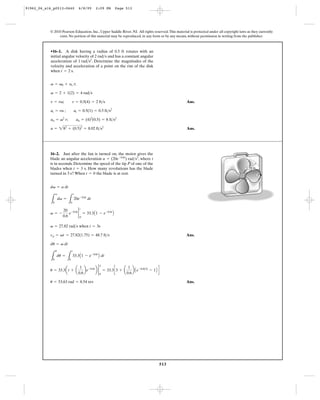
16–2. Just after the fan is turned on, the motor gives the
blade an angular acceleration , where t
is in seconds. Determine the speed of the tip P of one of the
blades when . How many revolutions has the blade
turned in 3 s? When the blade is at rest.t = 0
t = 3 s
a = (20e-0.6t
) rad>s2
P
1.75 ft
91962_06_s16_p0513-0640 6/8/09 2:09 PM Page 513
- 2. 514
Angular Motion: The angular acceleration of the drum can be determine by
applying Eq. 16–11.
Ans.
Applying Eq. 16–7 with and
, we have
Ans.
The angular displacement of the drum 4 s after it has completed 10 revolutions can
be determined by applying Eq. 16–6 with .
Ans.= (221.79 rad) * a
1 rev
2p rad
b = 35.3rev
= 0 + 35.45(4) +
1
2
(10.0)A42
B
u = u0 + v0 t +
1
2
ac t2
v0 = 35.45 rad>s
v = 35.45 rad>s = 35.4 rad>s
v2
= 0 + 2(10.0)(20p - 0)
v2
= v2
0 + 2ac (u - u0)
= 20p rad
u = (10 rev) * a
2p rad
1 rev
bac = a = 10.0 rad>s2
at = ar; 20 = a(2) a = 10.0 rad>s2
16–3. The hook is attached to a cord which is wound
around the drum. If it moves from rest with an
acceleration of , determine the angular acceleration
of the drum and its angular velocity after the drum has
completed 10 rev. How many more revolutions will the
drum turn after it has first completed 10 rev and the hook
continues to move downward for 4 s?
20 ft>s2
© 2010 Pearson Education, Inc., Upper Saddle River, NJ. All rights reserved.This material is protected under all copyright laws as they currently
exist. No portion of this material may be reproduced, in any form or by any means, without permission in writing from the publisher.
a ϭ 20 ft/s2
2 ft
91962_06_s16_p0513-0640 6/8/09 2:09 PM Page 514
- 3. 515
Angular Velocity: Here, .Applying Eq. 16–1, we have
By observing the above equation, the angular velocity is maximum if .
Thus, the maximum angular velocity is . The maximum speed of
point A can be obtained by applying Eq. 16–8.
Ans.
Angular Acceleration: Applying Eq. 16–2, we have
The tangential and normal components of the acceleration of point A can be
determined using Eqs. 16–11 and 16–12, respectively.
Thus,
Ans.aA = A -9 sin 3tut + 4.5 cos2
3tunB ft>s2
an = v2
r = (1.5 cos 3t)2
(2) = A4.5 cos2
3tB ft>s2
at = ar = (-4.5 sin 3t)(2) = (-9 sin 3t) ft>s2
a =
dv
dt
= (-4.5 sin 3t) rad>s2
(yA)max = vmax r = 1.50(2) = 3.00 ft>s
vmax = 1.50 rad>s
cos 3t = 1
v =
du
dt
= (1.5 cos 3t) rad>s
u = (0.5 sin 3t) rad>s
*16–4. The torsional pendulum (wheel) undergoes
oscillations in the horizontal plane, such that the angle of
rotation, measured from the equilibrium position, is given
by rad, where t is in seconds. Determine the
maximum velocity of point A located at the periphery of
the wheel while the pendulum is oscillating. What is the
acceleration of point A in terms of t?
u = (0.5 sin 3t)
© 2010 Pearson Education, Inc., Upper Saddle River, NJ. All rights reserved.This material is protected under all copyright laws as they currently
exist. No portion of this material may be reproduced, in any form or by any means, without permission in writing from the publisher.
A
u
2 ft
•16–5. The operation of reverse gear in an automotive
transmission is shown. If the engine turns shaft A at
, determine the angular velocity of the drive
shaft, .The radius of each gear is listed in the figure.vB
vA = 40 rad>s
B
vA ϭ 40 rad/sv
C
D
G
H
EF
rG ϭ 80 mm
rC ϭ rD ϭ 40 mm
rF ϭ 70 mm
rE ϭ rH ϭ 50 mm
B
A
Ans.vB = 89.6 rad>s
vF rF = vB rB : 64(70) = vB (50) vB = 89.6 rad>s
vE rE = vD rD : vE(50) = 80(40) vE = vF = 64 rad>s
rA vA = rC vC : 80(40) = 40vC vC = vD = 80 rad>s
91962_06_s16_p0513-0640 6/8/09 2:10 PM Page 515
- 4. 516
16–6. The mechanism for a car window winder is shown in
the figure. Here the handle turns the small cog C, which
rotates the spur gear S, thereby rotating the fixed-connected
lever AB which raises track D in which the window rests.
The window is free to slide on the track. If the handle is
wound at , determine the speed of points A and E
and the speed of the window at the instant .u = 30°vw
0.5 rad>s
© 2010 Pearson Education, Inc., Upper Saddle River, NJ. All rights reserved.This material is protected under all copyright laws as they currently
exist. No portion of this material may be reproduced, in any form or by any means, without permission in writing from the publisher.
20 mm
C
B
A
E
uF
D
S
0.5 rad/s
vw
50 mm
200 mm
200 mm
Ans.
Points A and E move along circular paths. The vertical component closes the
window.
Ans.vw = 40 cos 30° = 34.6 mm>s
vA = vE = vS rA = 0.2(0.2) = 0.04 m>s = 40 mm>s
vS =
vC
rS
=
0.01
0.05
= 0.2 rad>s
vC = vC rC = 0.5(0.02) = 0.01 m>s
16–7. The gear A on the drive shaft of the outboard motor
has a radius .and the meshed pinion gear B on the
propeller shaft has a radius . Determine the
angular velocity of the propeller in ,if the drive shaft
rotates with an angular acceleration ,
where t is in seconds. The propeller is originally at rest and
the motor frame does not move.
a = (400t3
) rad>s2
t = 1.5 s
rB = 1.2 in
rA = 0.5 in
2.20 in.
P
B
A
Angular Motion: The angular velocity of gear A at must be determined
first.Applying Eq. 16–2, we have
However, where is the angular velocity of propeller.Then,
Ans.vB =
rA
rB
vA = a
0.5
1.2
b(506.25) = 211 rad>s
vBvA rA = vB rB
vA = 100t4
|1.5 s
0 = 506.25 rad>s
L
vA
0
dv =
L
1.5 s
0
400t3
dt
dv = adt
t = 1.5 s
91962_06_s16_p0513-0640 6/8/09 2:10 PM Page 516
- 5. 517
*16–8. For the outboard motor in Prob. 16–7, determine
the magnitude of the velocity and acceleration of point P
located on the tip of the propeller at the instant .t = 0.75 s
© 2010 Pearson Education, Inc., Upper Saddle River, NJ. All rights reserved.This material is protected under all copyright laws as they currently
exist. No portion of this material may be reproduced, in any form or by any means, without permission in writing from the publisher.
2.20 in.
P
B
A
Angular Motion: The angular velocity of gear A at must be determined
first.Applying Eq. 16–2, we have
The angular acceleration of gear A at is given by
However, and where and are the angular
velocity and acceleration of propeller.Then,
Motion of P: The magnitude of the velocity of point P can be determined using
Eq. 16–8.
Ans.
The tangential and normal components of the acceleration of point P can be
determined using Eqs. 16–11 and 16–12, respectively.
The magnitude of the acceleration of point P is
Ans.aP = 2a2
r + a2
n = 212.892
+ 31.862
= 34.4 ft>s2
an = v2
B rP = A13.182
B a
2.20
12
b = 31.86 ft>s2
ar = aB rP = 70.31a
2.20
12
b = 12.89 ft>s2
yP = vB rP = 13.18a
2.20
12
b = 2.42 ft>s
aB =
rA
rB
aA = a
0.5
1.2
b(168.75) = 70.31 rad>s2
vB =
rA
rB
vA = a
0.5
1.2
b(31.64) = 13.18 rad>s
aBvBaA rA = aB rBvA rA = vB rB
aA = 400A0.753
B = 168.75 rad>s2
t = 0.75 s
vA = 100t4
|0.75 s
0
= 31.64 rad>s
L
vA
0
dv =
L
0.75 s
0
400t3
dt
dv = adt
t = 0.75 s
91962_06_s16_p0513-0640 6/8/09 2:10 PM Page 517
- 6. 518
•16–9. When only two gears are in mesh, the driving gear
A and the driven gear B will always turn in opposite
directions. In order to get them to turn in the same
direction an idler gear C is used. In the case shown,
determine the angular velocity of gear B when , if
gear A starts from rest and has an angular acceleration of
, where t is in seconds.aA = (3t + 2) rad>s2
t = 5 s
© 2010 Pearson Education, Inc., Upper Saddle River, NJ. All rights reserved.This material is protected under all copyright laws as they currently
exist. No portion of this material may be reproduced, in any form or by any means, without permission in writing from the publisher.
B
C75 mm
50 mm
Driving gearIdler gear
A
a50 mm
A
Ans.vB = 31.7 rad>s
vB (75) = 47.5(50)
vC = 47.5 rad>s
(47.5)(50) = vC (50)
vA = 1.5t2
+ 2t|t=5 = 47.5 rad>s
L
vA
0
dvA =
L
t
0
(3t + 2) dt
dv = a dt
Angular Motion: The angular velocity of the blade can be obtained by applying
Eq. 16–4.
Motion of P: The speed of point P can be determined using Eq. 16–8.
Ans.yP = vrP = 7.522(2.5) = 18.8 ft>s
v = 7.522 rad>s
L
v
5 rad>s
vdv =
L
4p
0
0.2udu
vdv = adu
16–10. During a gust of wind, the blades of the windmill
are given an angular acceleration of ,
where is in radians. If initially the blades have an angular
velocity of 5 , determine the speed of point P, located
at the tip of one of the blades, just after the blade has turned
two revolutions.
rad>s
u
a = (0.2u) rad>s2
2.5 ft
ϭ (0.2u) rad/s2
P
a
91962_06_s16_p0513-0640 6/8/09 2:10 PM Page 518
- 7. 519
Gears A and B will have the same angular velocity since they are mounted on the
same axle.Thus,
Wheel D is mounted on the same axle as gear C, which in turn is in mesh with
gear B.
Finally, the rim of can P is in mesh with wheel D.
Ans.vP = ¢
rD
rP
≤vD = a
7.5
40
b(4) = 0.75 rad>s
vP rP = vD rD
vD = vC = ¢
rB
rC
≤vB = a
10
25
b(10) = 4 rads>s
vC rC = vB rB
vB = vA = ¢
rs
rA
≤vs = a
5
20
b(40) = 10 rad>s
vA rA = vs rs
16–11. The can opener operates such that the can is driven
by the drive wheel D. If the armature shaft S on the motor
turns with a constant angular velocity of ,
determine the angular velocity of the can.The radii of S, can
P, drive wheel D, gears A, B, and C, are ,
, , , , and
, respectively.rC = 25 mm
rB = 10 mmrA = 20 mmrD = 7.5 mmrP = 40 mm
rS = 5 mm
40 rad>s
© 2010 Pearson Education, Inc., Upper Saddle River, NJ. All rights reserved.This material is protected under all copyright laws as they currently
exist. No portion of this material may be reproduced, in any form or by any means, without permission in writing from the publisher.
Motion of Pulley A: Here, . Since the angular
acceleration of shaft s is constant, its angular velocity can be determined from
Ans.vs = 274.6 rad>s
vs
2
= 02
+ 2(30)(400p - 0)
vs
2
= (vs)0
2
+ 2aC Cus - (us)0D
us = (200 rev)a
2p rad
1 rev
b = 400p rad
*16–12. If the motor of the electric drill turns the
armature shaft S with a constant angular acceleration of
, determine the angular velocity of the shaft
after it has turned 200 rev, starting from rest.
aS = 30 rad>s2
P
B
A
C
D
S
S
91962_06_s16_p0513-0640 6/8/09 2:11 PM Page 519
- 8. 520
Motion of Armature Shaft S: Here, . The angular
velocity of A can be determined from
When ,
Thus, the angular velocity of the shaft after it turns is
Ans.
The angular acceleration of the shaft is
When ,
Ans.as =
50
7.0831>2
= 18.8 rad>s2
t = 7.083 s
as =
dvs
dt
= 100a
1
2
t-1>2
b = a
50
t1>2
b rad>s2
vs = 100(7.083)1>2
= 266 rad>s
200 rev (t = 7.083 s)
t = 7.083 s
400p = 66.67t3>2
us = 400p rad
us = A66.67t3>2
Brad
us|us
0
= 66.67t3>22
t
0
L
us
0
us =
L
t
0
100t1>2
dt
L
dus =
L
vsdt
us = (200 rev)a
2prad
1 rev
b = 400p
•16–13. If the motor of the electric drill turns the armature
shaft S with an angular velocity of ,
determine the angular velocity and angular acceleration of
the shaft at the instant it has turned 200 rev,starting from rest.
vS = (100t1>2
) rad>s
© 2010 Pearson Education, Inc., Upper Saddle River, NJ. All rights reserved.This material is protected under all copyright laws as they currently
exist. No portion of this material may be reproduced, in any form or by any means, without permission in writing from the publisher.
S
91962_06_s16_p0513-0640 6/8/09 2:11 PM Page 520
- 9. 521
Motion of the Disk:We have
When ,
Solving for the positive root,
Also,
When ,
Motion of Point P: Using the result for and , the tangential and normal
components of the acceleration of point P are
Ans.
Ans.an = v2
rp = (13)2
a
6
12
b = 84.5 ft>s2
at = arp = 2a
6
12
b = 1 ft>s2
av
v = 2(5) + 3 = 13 rad>s
t = 5 s(u = 40 rad)
a =
dv
dt
= 2 rad>s2
t = 5 s
t2
+ 3t - 40 = 0
40 = t2
+ 3t
u = 40 rad
u = At2
+ 3tB rad
u ƒ
u
0 = At2
+ 3tB 2
t
0
L
u
0
du =
L
t
0
(2t + 3)dt
L
du =
L
vdt
16–14. A disk having a radius of 6 in. rotates about a fixed
axis with an angular velocity of ,where t is
in seconds. Determine the tangential and normal components
of acceleration of a point located on the rim of the disk at the
instant the angular displacement is .u = 40 rad
v = (2t + 3) rad>s
© 2010 Pearson Education, Inc., Upper Saddle River, NJ. All rights reserved.This material is protected under all copyright laws as they currently
exist. No portion of this material may be reproduced, in any form or by any means, without permission in writing from the publisher.
91962_06_s16_p0513-0640 6/8/09 2:11 PM Page 521
- 10. 522
Motion of Pulley A:The angular velocity of pulley A can be determined from
Using this result, the angular displacement of A as a function of t can be
determined from
When
Thus, when , is
Ans.aA = 27A5.06251>2
B = 60.8 rad>s2
aAt = 1 s
uA = c
3
2
(1)d
4
= 5.0625 rad
t = 1 s
uA = a
3
2
tb
4
rad
t = a
2
3
uA
1>4
b s
t|t
0
=
2
3
uA
1>4 2
uA
0
L
t
0
dt =
L
uA
0
duA
6uA
3>4
L
dt =
L
duA
vA
vA = A6uA
3>4
B rad>s
vA
2
2
2
v
0
A
= 18uA
3>2
ΗuA
0
L
vA
0
vAdvA =
L
uA
0
27uA
1>2
duA
L
vA dvA =
L
aA duA
16–15. The 50-mm-radius pulley A of the clothes
dryer rotates with an angular acceleration of
where is in radians. Determine its
angular acceleration when , starting from rest.t = 1 s
uAaA = (27u1>2
A ) rad>s2
,
© 2010 Pearson Education, Inc., Upper Saddle River, NJ. All rights reserved.This material is protected under all copyright laws as they currently
exist. No portion of this material may be reproduced, in any form or by any means, without permission in writing from the publisher.
50 mm
A
91962_06_s16_p0513-0640 6/8/09 2:12 PM Page 522
- 11. 523
Motion of Pulley A:The angular velocity of pulley A can be determined from
When
Ans.vA = 10(3) + 25A32
B = 225 rad>s
t = 3 s
vA = A10t + 25t2
Brad>s
vA|vA
0
= A10t + 25t2
B
2
t
0
L
vA
0
dvA =
L
t
0
(10 + 50t)dt
L
dvA =
L
aAdt
*16–16. If the 50-mm-radius motor pulley A of the clothes
dryer rotates with an angular acceleration of
, where t is in seconds, determine its
angular velocity when ,starting from rest.t = 3 s
aA = (10 + 50t) rad>s2
© 2010 Pearson Education, Inc., Upper Saddle River, NJ. All rights reserved.This material is protected under all copyright laws as they currently
exist. No portion of this material may be reproduced, in any form or by any means, without permission in writing from the publisher.
50 mm
A
Motion of the Shaft:The angular velocity of the shaft can be determined from
When
Motion of the Beater Brush: Since the brush is connected to the shaft by a non-slip
belt, then
Ans.vB = ¢
rs
rB
≤vs = a
0.25
1
b(256) = 64 rad>s
vB rB = vs rs
vs = 44
= 256 rad>s
t = 4 s
vS = At4
B rad>s
t = vS
1>4
t
2
t
0 = vS
1>42
vs
0
L
t
0
dt =
L
vs
0
dvS
4vS
3>4
L
dt =
L
dvS
aS
•16–17. The vacuum cleaner’s armature shaft S rotates
with an angular acceleration of , where is
in . Determine the brush’s angular velocity when
,starting from rest.The radii of the shaft and the brush
are 0.25 in. and 1 in., respectively. Neglect the thickness of the
drive belt.
t = 4 s
rad>s
va = 4v3>4
rad>s2
A S A S
91962_06_s16_p0513-0640 6/8/09 2:12 PM Page 523
- 12. 524
Angular Motion: The angular acceleration of gear B must be determined first. Here,
.Then,
The time for gear B to attain an angular velocity of can be obtained
by applying Eq. 16–5.
Ans.t = 100 s
50 = 0 + 0.5t
vB = (v0)B + aB t
vB = 50 rad>s
aB =
rA
rB
aA = a
25
100
b(2) = 0.5 rad>s2
aA rA = aB rB
16–18. Gear A is in mesh with gear B as shown. If A starts
from rest and has a constant angular acceleration of
, determine the time needed for B to attain an
angular velocity of .vB = 50 rad>s
aA = 2 rad>s2
© 2010 Pearson Education, Inc., Upper Saddle River, NJ. All rights reserved.This material is protected under all copyright laws as they currently
exist. No portion of this material may be reproduced, in any form or by any means, without permission in writing from the publisher.
rA ϭ 25 mm
rB ϭ 100 mm
A
a
B
91962_06_s16_p0513-0640 6/8/09 2:12 PM Page 524
- 13. 525
Angular Motion: The angular velocity of the blade after the blade has rotated
can be obtained by applying Eq. 16–7.
Motion of A and B: The magnitude of the velocity of point A and B on the blade can
be determined using Eq. 16–8.
Ans.
Ans.
The tangential and normal components of the acceleration of point A and B can be
determined using Eqs. 16–11 and 16–12 respectively.
The magnitude of the acceleration of points A and B are
Ans.
Ans.(a)B = = 2(at)2
B + (an)2
B = 25.002
+ 125.662
= 126 ft>s2
(a)A = 2(at)2
A + (an)2
A = 210.02
+ 251.332
= 252 ft>s2
(an)B = v2
rB = A3.5452
B(10) = 125.66 ft>s2
(at)B = arB = 0.5(10) = 5.00 ft>s2
(an)A = v2
rA = A3.5452
B(20) = 251.33 ft>s2
(at)A = arA = 0.5(20) = 10.0 ft>s2
vB = vrB = 3.545(10) = 35.4 ft>s
yA = vrA = 3.545(20) = 70.9 ft>s
v = 3.545 rad>s
v2
= 02
+ 2(0.5)(4p - 0)
v2
= v2
0 + 2ac (u - u0)
2(2p) = 4p rad
16–19. The vertical-axis windmill consists of two blades
that have a parabolic shape. If the blades are originally at
rest and begin to turn with a constant angular acceleration
of , determine the magnitude of the velocity
and acceleration of points A and B on the blade after the
blade has rotated through two revolutions.
ac = 0.5 rad>s2
© 2010 Pearson Education, Inc., Upper Saddle River, NJ. All rights reserved.This material is protected under all copyright laws as they currently
exist. No portion of this material may be reproduced, in any form or by any means, without permission in writing from the publisher.
20 ft
B
A
ac ϭ 0.5 rad/s2
10 ft
91962_06_s16_p0513-0640 6/8/09 2:12 PM Page 525
- 14. 526
Angular Motion: The angular velocity of the blade at can be obtained by
applying Eq. 16–5.
Motion of A and B: The magnitude of the velocity of points A and B on the blade
can be determined using Eq. 16–8.
Ans.
Ans.
The tangential and normal components of the acceleration of points A and B can be
determined using Eqs. 16–11 and 16–12 respectively.
The magnitude of the acceleration of points A and B are
Ans.
Ans.(a)B = 2(at)2
B + (an)2
B = 25.002
+ 40.02
= 40.3 ft>s2
(a)A = 2(at)2
A + (an)2
A = 210.02
+ 80.02
= 80.6 ft>s2
(an)B = v2
rB = A2.002
B(10) = 40.0 ft>s2
(at)B = arB = 0.5(10) = 5.00 ft>s2
(an)A = v2
rA = A2.002
B(20) = 80.0 ft>s2
(at)A = arA = 0.5(20) = 10.0 ft>s2
yB = vrB = 2.00(10) = 20.0 ft>s
yA = vrA = 2.00(20) = 40.0 ft>s
v = v0 + ac t = 0 + 0.5(4) = 2.00 rad>s
t = 4 s
*16–20. The vertical-axis windmill consists of two blades
that have a parabolic shape. If the blades are originally at rest
and begin to turn with a constant angular acceleration of
, determine the magnitude of the velocity and
acceleration of points A and B on the blade when .t = 4 s
ac = 0.5 rad>s2
© 2010 Pearson Education, Inc., Upper Saddle River, NJ. All rights reserved.This material is protected under all copyright laws as they currently
exist. No portion of this material may be reproduced, in any form or by any means, without permission in writing from the publisher.
20 ft
B
A
ac ϭ 0.5 rad/s2
10 ft
Ans.
Ans.
Ans.an = v2
r; (aA)n = (11)2
(2) = 242 ft>s2
at = ra; (aA)t = 2(6) = 12.0 ft>s2
v = rv; vA = 2(11) = 22 ft>s
v = 8 + 6(0.5) = 11 rad>s
v = v0 + ac t
16.21. The disk is originally rotating at If it is
subjected to a constant angular acceleration of
determine the magnitudes of the velocity and the n and t
components of acceleration of point A at the instant
t = 0.5 s.
a = 6 rad>s2
,
v0 = 8 rad>s.
2 ft
1.5 ft
B
A
V0 ϭ 8 rad/s
91962_06_s16_p0513-0640 6/8/09 2:13 PM Page 526
- 15. 527
Ans.
Ans.
Ans.(aB)n = v2
r = (14.66)2
(1.5) = 322 ft>s2
(aB)t = ar = 6(1.5) = 9.00 ft>s2
vB = vr = 14.66(1.5) = 22.0 ft>s
v = 14.66 rad>s
v2
= (8)2
+ 2(6)[2(2p) - 0]
v2
= v2
0 + 2ac (u - u0)
16–22. The disk is originally rotating at If it
is subjected to a constant angular acceleration of
determine the magnitudes of the velocity and
the n and t components of acceleration of point B just after
the wheel undergoes 2 revolutions.
a = 6 rad>s2
,
v0 = 8 rad>s.
© 2010 Pearson Education, Inc., Upper Saddle River, NJ. All rights reserved.This material is protected under all copyright laws as they currently
exist. No portion of this material may be reproduced, in any form or by any means, without permission in writing from the publisher.
16–23. The blade C of the power plane is driven by pulley
A mounted on the armature shaft of the motor. If the
constant angular acceleration of pulley A is ,
determine the angular velocity of the blade at the instant A
has turned 400 rev, starting from rest.
aA = 40 rad>s2
2 ft
1.5 ft
B
A
V0 ϭ 8 rad/s
A
B
C
25 mm
50 mm
75 mm
Motion of Pulley A: Here, . Since the angular
velocity can be determined from
Motion of Pulley B: Since blade C and pulley B are on the same axle, both will have
the same angular velocity. Pulley B is connected to pulley A by a nonslip belt.Thus,
Ans.vC = vB = ¢
rA
rB
≤vA = a
25
50
b(448.39) = 224 rad>s
vB rB = vA rA
vA = 448.39 rad>s
vA
2
= 02
+ 2(40)(800p - 0)
vA
2
= (vA)0
2
+ 2aC CuA - (uA)0D
uA = (400 rev)a
2p rad
1 rev
b = 800p rad
91962_06_s16_p0513-0640 6/8/09 2:13 PM Page 527
- 16. 528
Motion of the Gear A:The angular velocity of gear A can be determined from
When
Motion of Gears B, C, and D: Gears B and C which are mounted on the same axle
will have the same angular velocity. Since gear B is in mesh with gear A, then
Also, gear D is in mesh with gear C.Then
Ans.vD = ¢
rC
rD
≤vC = a
40
100
b(55.90) = 22.4 rad>s
vD rD = vC rC
vC = vB = ¢
rA
rB
≤vA = a
25
100
b(223.61) = 55.90 rad>s
vB rB = vA rA
vA = 20A53>2
B = 223.61 rad>s
t = 5 s
vA = A20t3>2
B rad>s
vA Η
vA
0
= 20t3>2 2
t
0
L
vA
0
dvA =
L
t
0
30t1>2
dt
L
dvA =
L
adt
*16–24. For a short time the motor turns gear A with an
angular acceleration of , where t is in
seconds. Determine the angular velocity of gear D when
, starting from rest. Gear A is initially at rest.The radii
of gears A, B, C, and D are , ,
, and , respectively.rD = 100 mmrC = 40 mm
rB = 100 mmrA = 25 mm
t = 5 s
aA = (30t1>2
) rad>s2
© 2010 Pearson Education, Inc., Upper Saddle River, NJ. All rights reserved.This material is protected under all copyright laws as they currently
exist. No portion of this material may be reproduced, in any form or by any means, without permission in writing from the publisher.
A
B
C
D
91962_06_s16_p0513-0640 6/8/09 2:14 PM Page 528
- 17. 529
Motion of Wheel A: Here,
when . Since the angular acceleration of gear
A is constant, it can be determined from
Thus, the angular velocity of gear A when is
Motion of Gears B, C, and D: Gears B and C which are mounted on the same axle
will have the same angular velocity. Since gear B is in mesh with gear A, then
Also, gear D is in mesh with gear C.Then
Ans.vD = ¢
rC
rD
≤vC = a
40
100
b(29.45) = 11.8 rad>s
vD rD = vC rC
vC = vB = ¢
rA
rB
≤vA = a
25
100
b(117.81) = 29.45 rad>s
vB rB = vB rA
= 117.81 rad>s
= 0 + 39.27(3)
vA = AvAB0 + aA t
t = 3 s
aA = 39.27 rad>s2
(100p)2
= 02
+ 2aA (400p - 0)
vA
2
= (vA)0
2
+ 2aA CuA - (uA)0D
uA = (200 rev)a
2p rad
1 rev
b = 400p rad
vA = a3000
rev
min
b a
1 min
60 s
b a
2p rad
1rev
b = 100p rad>s
•16–25. The motor turns gear A so that its angular velocity
increases uniformly from zero to after the shaft
turns 200 rev. Determine the angular velocity of gear D when
. The radii of gears A, B, C, and D are ,
, , and , respectively.rD = 100 mmrC = 40 mmrB = 100 mm
rA = 25 mmt = 3 s
3000 rev>min
© 2010 Pearson Education, Inc., Upper Saddle River, NJ. All rights reserved.This material is protected under all copyright laws as they currently
exist. No portion of this material may be reproduced, in any form or by any means, without permission in writing from the publisher.
A
B
C
D
91962_06_s16_p0513-0640 6/8/09 2:14 PM Page 529
- 18. 530
Motion of Part C: Since the shaft that turns the robot’s arm is attached to gear D,
then the angular velocity of the robot’s arm . The distance of
part C from the rotating shaft is . The
magnitude of the velocity of part C can be determined using Eq. 16–8.
Ans.
The tangential and normal components of the acceleration of part C can be
determined using Eqs. 16–11 and 16–12 respectively.
The magnitude of the acceleration of point C is
Ans.aC = 2a2
t + a2
n = 202
+ 106.072
= 106 ft>s2
an = v2
R rC = A5.002
B(4.243) = 106.07 ft>s2
at = arC = 0
yC = vR rC = 5.00(4.243) = 21.2 ft>s
rC = 4 cos 45° + 2 sin 45° = 4.243 ft
vR = vD = 5.00 rad>s
16–26. Rotation of the robotic arm occurs due to linear
movement of the hydraulic cylinders A and B. If this motion
causes the gear at D to rotate clockwise at 5 , determine
the magnitude of velocity and acceleration of the part C
held by the grips of the arm.
rad>s
© 2010 Pearson Education, Inc., Upper Saddle River, NJ. All rights reserved.This material is protected under all copyright laws as they currently
exist. No portion of this material may be reproduced, in any form or by any means, without permission in writing from the publisher.
4 ft
2 ft
A
D
C
B 3 ft
45Њ
91962_06_s16_p0513-0640 6/8/09 2:14 PM Page 530
- 19. 531
16–27. For a short time, gear A of the automobile
starter rotates with an angular acceleration of
, where t is in seconds. Determine
the angular velocity and angular displacement of gear B
when , starting from rest.The radii of gears A and B
are 10 mm and 25 mm, respectively.
t = 2 s
aA = (450t2
+ 60) rad>s2
© 2010 Pearson Education, Inc., Upper Saddle River, NJ. All rights reserved.This material is protected under all copyright laws as they currently
exist. No portion of this material may be reproduced, in any form or by any means, without permission in writing from the publisher.
A
B
Motion of Gear A: Applying the kinematic equation of variable angular
acceleration,
When ,
When
Motion of Gear B: Since gear B is meshed with gear A, Fig. a, then
Ans.
Ans.= 288 rad
= 720¢
0.01
0.025
≤
uB = uA¢
rA
rB
≤
= 528 rad>s
= (1320)¢
0.01
0.025
≤
vB = vA¢
rA
rB
≤
vp = vA rA = vB rB
uA = 37.5(2)4
+ 30(2)2
= 720 rad
t = 2 s
uA = A37.5t4
+ 30t2
B rad
uAΗ
uA
0
= 37.5t4
+ 30t2 2
t
0
L
uA
0
duA =
L
t
0
A150t3
+ 60tBdt
L
duA =
L
vA dt
vA = 150(2)3
+ 60(2) = 1320 rad>s
t = 2 s
vA = A150t3
+ 60tB rad>s
vAΗ
vA
0 = 150t3
+ 60t 2
t
0
L
vA
0
dvA =
L
t
0
A450t2
+ 60Bdt
L
dvA
L
aAdt
91962_06_s16_p0513-0640 6/8/09 2:15 PM Page 531
- 20. 532
*16–28. For a short time, gear A of the automobile starter
rotates with an angular acceleration of ,
where is in . Determine the angular velocity of gear B
after gear A has rotated 50 rev, starting from rest.The radii of
gears A and B are 10 mm and 25 mm, respectively.
rad>sv
aA = (50v1>2
) rad>s2
© 2010 Pearson Education, Inc., Upper Saddle River, NJ. All rights reserved.This material is protected under all copyright laws as they currently
exist. No portion of this material may be reproduced, in any form or by any means, without permission in writing from the publisher.
A
B
Motion of Gear A:We have
The angular displacement of gear A can be determined using this result.
When ,
Thus, the angular velocity of gear A at is
Motion of Gear B: Since gear B is meshed with gear A, Fig. a, then
Ans.= 329 rad>s
= 821.88a
0.01
0.025
b
vB = vA¢
rA
rB
≤
vp = vA rA = vB rB
vA = 625(1.1472
) = 821.88 rad>s
t = 1.147 s(uA = 100p rad)
t = 1.147 s
100p = 208.33t3
uA = 50 reva
2p rad
1 rev
b = 100p rad
uA = A208.33t3
B rad
uAΗ
uA
0 = 208.33t3 2
t
0
L
uA
0
duA =
L
t
0
A625t2
Bdt
L
duA =
L
vA dt
vA = A625t2
B rad>s
tΗ
t
0
=
1
25
vA
1>2 2
vA
0
L
t
0
dt =
L
vA
0
dvA
50vA
1>2
L
dt =
L
dvA
aA
91962_06_s16_p0513-0640 6/8/09 2:15 PM Page 532
- 21. 533
•16–29. Gear A rotates with a constant angular velocity of
. Determine the largest angular velocity of
gear B and the speed of point C.
vA = 6 rad>s
© 2010 Pearson Education, Inc., Upper Saddle River, NJ. All rights reserved.This material is protected under all copyright laws as they currently
exist. No portion of this material may be reproduced, in any form or by any means, without permission in writing from the publisher.
100 mm
B
C
A
100 mm
100 mm
100 mm
vB
vAϭ 6 rad/s
16–30. If the operator initially drives the pedals at
and then begins an angular acceleration of
, determine the angular velocity of the flywheel
when . Note that the pedal arm is fixed connected
to the chain wheel A, which in turn drives the sheave B
using the fixed connected clutch gear D. The belt wraps
around the sheave then drives the pulley E and fixed-
connected flywheel.
t = 3 sF
30 rev>min2
20 rev>min,
When rA is max., rB is min.
Ans.
Ans.vC = 0.6 m>s
vC = (vB)max rC = 8.49A0.0522B
(vB)max = 8.49 rad>s
(vB)max = 6a
rA
rB
b = 6¢
5022
50
≤
vB (rB) = vA rA
(rB)min = (rA)min = 50 mm
(rB)max = (rA)max = 5022 mm
D
B
A
rA ϭ 125 mm
rD ϭ 20 mm
rB ϭ 175 mm
rE ϭ 30 mm
F
E
Ans.vF = 784 rev>min
vE = 783.9 rev>min
134.375(175) = vE(30)
vB rB = vE rE
vD = vB = 134.375
21.5(125) = vD (20)
vA rA = vD rD
vA = 20 + 30a
3
60
b = 21.5 rev>min
v = v0 + ac t
91962_06_s16_p0513-0640 6/8/09 2:15 PM Page 533
- 22. 534
16–31. If the operator initially drives the pedals at
and then begins an angular acceleration of
, determine the angular velocity of the flywheel
after the pedal arm has rotated 2 revolutions. Note that
the pedal arm is fixed connected to the chain wheel A,
which in turn drives the sheave B using the fixed-
connected clutch gear D.The belt wraps around the sheave
then drives the pulley E and fixed-connected flywheel.
F
8 rev>min2
12 rev>min,
© 2010 Pearson Education, Inc., Upper Saddle River, NJ. All rights reserved.This material is protected under all copyright laws as they currently
exist. No portion of this material may be reproduced, in any form or by any means, without permission in writing from the publisher.
D
B
A
rA ϭ 125 mm
rD ϭ 20 mm
rB ϭ 175 mm
rE ϭ 30 mm
F
E
Ans.vF = 484 rev>min
vE = 483.67
82.916(175) = vE(30)
vB rB = vE rE
vD = vD = 82.916
13 266(125) = vD (20)
vA rA = vD rD
v = 13 266 rev>min
v2
= (12)2
+ 2(8)(2 - 0)
v2
= v2
0 + 2ac (u - u0)
91962_06_s16_p0513-0640 6/8/09 2:16 PM Page 534
- 23. 535
Angular Motion: The angular velocity between wheels A and B can be related by
During time dt, the volume of the tape exchange between the wheel is
[1]
Applying Eq. 16–2 with , we have
[2]
Substituting Eq.[1] into [2] yields
[3]
The volume of tape coming out from wheel A in time dt is
[4]
Substitute Eq.[4] into [3] gives
Ans.aB =
v2
A T
2pr3
B
Ar2
A + r2
BB
drA
dt
=
vA T
2p
2prA drA = (vA rA dt) T
aB = vA a
r2
A + r2
B
r3
B
b
drA
dt
aB =
dvB
dt
=
d
dt
c
rA
rB
vA d = vA a
1
rB
drA
dt
-
rA
r2
B
drB
dt
b
vB =
rA
rB
vA
drB = - ¢
rA
rB
≤drA
-2prB drB = 2prA drA
vA rA = vB rB or vB =
rA
rB
vA
*16–32. The drive wheel A has a constant angular velocity
of . At a particular instant, the radius of rope wound on
each wheel is as shown. If the rope has a thickness T,
determine the angular acceleration of wheel B.
vA
© 2010 Pearson Education, Inc., Upper Saddle River, NJ. All rights reserved.This material is protected under all copyright laws as they currently
exist. No portion of this material may be reproduced, in any form or by any means, without permission in writing from the publisher.
B
A
A v
rB rA
91962_06_s16_p0513-0640 6/8/09 2:16 PM Page 535
- 24. 536
When
Ans.
Ans.
The point having the greatest velocity and acceleration is located furthest from the
axis of rotation.This is at , where .
Hence,
Ans.
Ans.aP = 205 m>s2
aP = 2(at)2
P + (an)2
P = 2(7.532)2
+ (204.89)2
(an)P = v2
(z) = (28.63)2
(0.25) = 204.89 m>s2
(at)P = a(z) = A1.5e3
B(0.25) = 7.532 m>s2
vP = v(z) = 28.63(0.25) = 7.16 m>s
z = 0.25 sin (p0.5) = 0.25 my = 0.5 m
u = 1.5Ce3
- 3 - 1D = 24.1 rad
v = 1.5Ce3
- 1D = 28.63 = 28.6 rad>s
t = 3 s
u = 1.5Cet
- tDt
0 = 1.5Cet
- t - 1D
L
u
0
du = 1.5
L
t
0
Cet
- 1D dt
du = v dt
v = 1.5et
Ηt
0 = 1.5Cet
- 1D
L
v
0
dv =
L
t
0
1.5et
dt
dv = a dt
•16–33. If the rod starts from rest in the position shown
and a motor drives it for a short time with an angular
acceleration of , where t is in seconds,
determine the magnitude of the angular velocity and the
angular displacement of the rod when . Locate the
point on the rod which has the greatest velocity and
acceleration, and compute the magnitudes of the velocity
and acceleration of this point when . The rod is
defined by where the argument for the
sine is given in radians and y is in meters.
z = 0.25 sin(py) m,
t = 3 s
t = 3 s
a = (1.5et
) rad>s2
© 2010 Pearson Education, Inc., Upper Saddle River, NJ. All rights reserved.This material is protected under all copyright laws as they currently
exist. No portion of this material may be reproduced, in any form or by any means, without permission in writing from the publisher.
z
x y
1 m
z = 0.25 sin ( y)π
91962_06_s16_p0513-0640 6/8/09 2:16 PM Page 536
- 25. 537
We will first express the angular velocity of the plate in Cartesian vector form.The
unit vector that defines the direction of is
Thus,
Since is constant
For convenience, is chosen. The velocity and acceleration of
point C can be determined from
Ans.
and
Ans.= [38.4i - 64.8j + 40.8k]m>s2
= 0 + (-6i + 4j + 12k) * [(-6i + 4j + 12k) * (-0.3i + 0.4j)]
aC = a * rC
= [-4.8i - 3.6j - 1.2k] m>s
= (-6i + 4j + 12k) * (-0.3i + 0.4j)
vC = v * rC
rC = [-0.3i + 0.4j] m
a = 0
v
v = vuOA = 14a -
3
7
i +
2
7
j +
6
7
kb = [-6i + 4j + 12k] rad>s
uOA =
-0.3i + 0.2j + 0.6k
2(-0.3)2
+ 0.22
+ 0.62
= -
3
7
i +
2
7
j +
6
7
k
v
v
16–34. If the shaft and plate rotate with a constant
angular velocity of , determine the velocity
and acceleration of point C located on the corner of the
plate at the instant shown. Express the result in Cartesian
vector form.
v = 14 rad>s
© 2010 Pearson Education, Inc., Upper Saddle River, NJ. All rights reserved.This material is protected under all copyright laws as they currently
exist. No portion of this material may be reproduced, in any form or by any means, without permission in writing from the publisher.
x y
C
O
D
B
z
0.2 m
0.3 m
0.3 m
0.4 m
0.4 m
0.6 m
A
v
a
91962_06_s16_p0513-0640 6/8/09 2:17 PM Page 537
- 26. 538
We will first express the angular velocity of the plate in Cartesian vector form.The
unit vector that defines the direction of and is
Thus,
For convenience, is chosen. The velocity and acceleration of
point D can be determined from
Ans.
and
= [4.8i + 3.6j + 1.2k]m>s
= (-6i + 4j + 12k) * (-0.3i + 0.4j)
vD = v * rD
rD = [-0.3i + 0.4j] m
a = auOA = 7a -
3
7
i +
2
7
j +
6
7
kb = [-3i + 2j + 6k] rad>s
v = vuOA = 14a -
3
7
i +
2
7
j +
6
7
kb = [-6i + 4j + 12k] rad>s
uOA =
-0.3i + 0.2j + 0.6k
2(-0.3)2
+ 0.22
+ 0.62
= -
3
7
i +
2
7
j +
6
7
k
av
v
16–35. At the instant shown, the shaft and plate rotates
with an angular velocity of and angular
acceleration of . Determine the velocity and
acceleration of point D located on the corner of the plate at
this instant. Express the result in Cartesian vector form.
a = 7 rad>s2
v = 14 rad>s
© 2010 Pearson Education, Inc., Upper Saddle River, NJ. All rights reserved.This material is protected under all copyright laws as they currently
exist. No portion of this material may be reproduced, in any form or by any means, without permission in writing from the publisher.
x y
C
O
D
B
z
0.2 m
0.3 m
0.3 m
0.4 m
0.4 m
0.6 m
A
v
a
= (-3i + 2j + 6k) * (-0.3i + 0.4j) + (-6i + 4j + 12k) * [(-6i + 4j + 12k) * (-0.3i + 0.4j)]
aD = a * rD - v2
rD
Ans.= [-36.0i + 66.6j + 40.2k]m>s2
91962_06_s16_p0513-0640 6/8/09 2:17 PM Page 538
- 27. 539
Position Coordinate Equation: From the geometry,
[1]
Time Derivatives: Taking the time derivative of Eq. [1], we have
[2]
However, and , then from Eq. [2]
Ans.
Note: Negative sign indicates that is directed in the opposite direction to that of
positive x.
y
y = -2 csc2
u(5) = A -10 csc2
uB
du
dt
= v = 5 rad>s
dx
dt
= y
dx
dt
= -2 csc2
u
du
dt
x =
2
tan u
= 2 cot u
*16–36. Rod CD presses against AB, giving it an angular
velocity. If the angular velocity of AB is maintained at
, determine the required magnitude of the
velocity v of CD as a function of the angle of rod AB.u
v = 5 rad>s
© 2010 Pearson Education, Inc., Upper Saddle River, NJ. All rights reserved.This material is protected under all copyright laws as they currently
exist. No portion of this material may be reproduced, in any form or by any means, without permission in writing from the publisher.
B
D
C
Au
v
v
x
2 ft
Position Coordinate Equation:
Time Derivatives:
Ans.y
#
= yy = 4 cos uu
#
= 4 cos ua
0.375
sin u
b = 1.5 cot u
-1.5 = -4 sin uu
#
u
#
=
0.375
sin u
x
#
= -4 sin uu
#
However, x
#
= -yA = -1.5 ft>s
x = 4 cos u y = 4 sin u
•16–37. The scaffold S is raised by moving the roller at A
toward the pin at B. If A is approaching B with a speed of
1.5 , determine the speed at which the platform rises as a
function of . The 4-ft links are pin connected at their
midpoint.
u
ft>s
D E
B
uA1.5 ft/s
S
C
4 ft
91962_06_s16_p0513-0640 6/8/09 2:17 PM Page 539
- 28. 540
Position Coordinate Equation: From the geometry,
[1]
Time Derivatives: Taking the time derivative of Eq. [1], we have
[2]
Since is directed toward negative x, then .Also, .
From Eq.[2],
Ans.
Here, .Then from the above expression
[3]
However, and . Substitute these values into
Eq.[3] yields
Ans.a =
y0
a
sin 2ua
y0
a
sin2
ub = a
y0
a
b
2
sin 2u sin2
u
v =
du
dt
=
y0
a
sin2
u2 sin u cos u = sin 2u
a =
y0
a
(2 sin u cos u)
du
dt
a =
dv
dt
v =
y0
a csc2
u
=
y0
a
sin2
u
-y0 = -a csc2
u(v)
du
dt
= v
dx
dt
= -y0y0
dx
dt
= -a csc2
u
du
dt
x =
a
tan u
= a cot u
16–38. The block moves to the left with a constant
velocity . Determine the angular velocity and angular
acceleration of the bar as a function of .u
v0
© 2010 Pearson Education, Inc., Upper Saddle River, NJ. All rights reserved.This material is protected under all copyright laws as they currently
exist. No portion of this material may be reproduced, in any form or by any means, without permission in writing from the publisher.
a
u
x v0
91962_06_s16_p0513-0640 6/8/09 2:18 PM Page 540
- 29. 541
16–39. Determine the velocity and acceleration of platform
P as a function of the angle of cam C if the cam rotates with
a constant angular velocity . The pin connection does not
cause interference with the motion of P on C.The platform is
constrained to move vertically by the smooth vertical guides.
V
u
© 2010 Pearson Education, Inc., Upper Saddle River, NJ. All rights reserved.This material is protected under all copyright laws as they currently
exist. No portion of this material may be reproduced, in any form or by any means, without permission in writing from the publisher.
r
P
C
u
y
Position Coordinate Equation: From the geometry.
[1]
Time Derivatives: Taking the time derivative of Eq. [1], we have
[2]
However and . From Eq.[2],
Ans.
Taking the time derivative of the above expression, we have
[4]
However and . From Eq.[4],
Ans.
Note: Negative sign indicates that a is directed in the opposite direction to that of
positive y.
a = -v2
r sin u
a =
dv
dt
= 0a =
dy
dt
= racos u
dv
dt
- v2
sin ub
dy
dt
= rcv(-sin u)
du
dt
+ cos u
dv
dt
d
y = vr cos u
v =
du
dt
y =
dy
dt
dy
dt
= r cos u
du
dt
y = r sin u + r
91962_06_s16_p0513-0640 6/8/09 2:36 PM Page 541
- 30. 542
As shown by the construction, as A rolls through the arc , the center of the
disk moves through the same distance . Hence,
Ans.
Link
Thus, A makes 2 revolutions for each revolution of CD. Ans.
2uCD = uA
s¿ = 2ruCD = s = uA r
vA = 33.3 rad>s
5 = vA (0.15)
s
#
= u
#
A r
s = uA r
s¿ = s
s = uA r
*16–40. Disk A rolls without slipping over the surface of
the fixed cylinder B. Determine the angular velocity of A if
its center C has a speed . How many revolutions
will A rotate about its center just after link DC completes
one revolution?
vC = 5 m>s
© 2010 Pearson Education, Inc., Upper Saddle River, NJ. All rights reserved.This material is protected under all copyright laws as they currently
exist. No portion of this material may be reproduced, in any form or by any means, without permission in writing from the publisher.
C
D
B
A
vC ϭ 5 m/s
150 mm
150 mm
vA
91962_06_s16_p0513-0640 6/8/09 2:36 PM Page 542
- 31. 543
•16–41. Crank AB rotates with a constant angular
velocity of 5 . Determine the velocity of block C and
the angular velocity of link BC at the instant .u = 30°
rad>s
© 2010 Pearson Education, Inc., Upper Saddle River, NJ. All rights reserved.This material is protected under all copyright laws as they currently
exist. No portion of this material may be reproduced, in any form or by any means, without permission in writing from the publisher.
A
u
B
C
5 rad/s
600 mm 300 mm
150 mm
Position Coordinate Equation: From the geometry,
[1]
[2]
Eliminate from Eqs. [1] and [2] yields
[3]
Time Derivatives: Taking the time derivative of Eq. [3], we have
[4]
However, and , then from Eq.[4]
[5]
At the instant , . Substitute into Eq.[5] yields
Ans.
Taking the time derivative of Eq. [2], we have
[6]
However, and , then from Eq.[6]
[7]
At the instant , from Eq.[2], . From Eq.[7]
Ans.
Note: Negative sign indicates that is directed in the opposite direction to that of
positive x.
yC
vBC = a
2 cos 30°
cos 30.0°
b(5) = 10.0 rad>s
f = 30.0°u = 30°
vBC = a
2 cos u
cos f
bvAB
du
dt
= vAB
df
dt
= vBC
0.6 cos u
du
dt
= 0.3 cos f
df
dt
yC = B -0.6 sin 30° +
0.15(2 cos 30° - 4 sin 60°)
22 sin 30° - 4 sin2
30° + 0.75
R(5) = -3.00 m>s
vAB = 5 rad>su = 30°
yC = B -0.6 sin u +
0.15(2 cos u - 4 sin 2u)
22 sin u - 4 sin2
u + 0.75
RvAB
du
dt
= vAB
dx
dt
= yC
dx
dt
= B -0.6 sin u +
0.15(2 cos u - 4 sin 2u)
22 sin u - 4 sin2
u + 0.75
R
du
dt
x = 0.6 cos u + 0.322 sin u - 4 sin2
u + 0.75
f
0.6 sin u = 0.15 + 0.3 sin f
x = 0.6 cos u + 0.3 cos f
91962_06_s16_p0513-0640 6/8/09 2:36 PM Page 543
- 32. 544
Position Coordinate Equation:
Time Derivatives:
Ans.yB = a
h
d
byA
x
#
= a
h
d
by
#
x = a
h
d
by
tan u =
h
x
=
d
y
16–42. The pins at A and B are constrained to move in the
vertical and horizontal tracks. If the slotted arm is causing A
to move downward at , determine the velocity of B as a
function of u.
vA
© 2010 Pearson Education, Inc., Upper Saddle River, NJ. All rights reserved.This material is protected under all copyright laws as they currently
exist. No portion of this material may be reproduced, in any form or by any means, without permission in writing from the publisher.
90Њ
vA
y
d
h
x
B
u
A
91962_06_s16_p0513-0640 6/8/09 2:36 PM Page 544
- 33. 545
Position Coordinate Equation: From the geometry.
[1]
Time Derivatives: Taking the time derivative of Eq.[1], we have
[2]
Since is directed toward positive x, then . Also, . From the
geometry, and . Substitute these values into Eq.[2], we
have
Ans.
Taking the time derivative of Eq. [2], we have
[3]
Here, and . Substitute into Eq.[3], we have
[4]
However, , and . Substitute
these values into Eq.[4] yields
Ans.a = B
r(2x2
- r2
)
x2
(x2
- r2
)3>2
Ry2
A
v = - ¢
r
x2x2
- r2
≤yAcos u =
2x2
- r2
x
sin u =
r
x
a = ¢
1 + cos2
u
sin u cos u
≤v2
0 =
r
sin2
u
B ¢
1 + cos2
u
sin u
≤v2
- a cos uR
d2
u
dt2
= a
d2
x
dt2
= a = 0
d2
x
dt2
=
r
sin2
u
= B ¢
1 + cos2
u
sin u
≤ a
du
dt
b
2
- cos u
d2
u
dt2 R
v = - ¢
r
x2x2
- r2
≤yA
yA = - ¢
rA 2x2
- r2
>xB
(r>x)2 ≤v
cos u =
2x2
- r2
x
sin u =
r
x
du
dt
= v
dx
dt
= yAy0
dx
dt
= -
r cos u
r sin2
u
du
dt
x =
r
sin u
16–43. End A of the bar moves to the left with a constant
velocity . Determine the angular velocity and angular
acceleration of the bar as a function of its position x.A
VvA
© 2010 Pearson Education, Inc., Upper Saddle River, NJ. All rights reserved.This material is protected under all copyright laws as they currently
exist. No portion of this material may be reproduced, in any form or by any means, without permission in writing from the publisher.
A
,
x
vA
r
u
91962_06_s16_p0513-0640 6/8/09 2:36 PM Page 545
- 34. 546
Position Coordinate Equation: From the geometry,
[1]
Time Derivatives: Taking the time derivative of Eq. [1], we have
[2]
However and . From Eq.[2],
[3]
At the instant , , then substitute these values into Eq.[3] yields
Ans.
Taking the time derivative of Eq. [3], we have
[4]
However and . From Eq.[4],
[5]
At the instant , and , then substitute these values
into Eq.[5] yields
Ans.
Note: Negative sign indicates that a is directed in the opposite direction to that of
positive x.
a = 0.12A2 cos 30° - 42
sin 30°B = -0.752 m>s2
a = 2 rad>s2
v = 4 rad>su = 30°
a = 0.12Aa cos u - v2
sin uB
a =
dv
dt
a =
dy
dt
= 0.12acos u
dv
dt
- v2
sin ub
dy
dt
= 0.12cv(-sin u)
du
dt
+ cos u
dv
dt
d
y = 0.12(4) cos 30° = 0.416 m>s
v = 4 rad>su = 30°
y = 0.12v cos u
v =
du
dt
y =
dx
dt
dx
dt
= 0.12 cos u
du
dt
x = 0.12 sin u + 0.15
*16–44. Determine the velocity and acceleration of the
plate at the instant , if at this instant the circular cam
is rotating about the fixed point O with an angular velocity
and an angular acceleration .a = 2 rad>s2
v = 4 rad>s
u = 30°
© 2010 Pearson Education, Inc., Upper Saddle River, NJ. All rights reserved.This material is protected under all copyright laws as they currently
exist. No portion of this material may be reproduced, in any form or by any means, without permission in writing from the publisher.
O
120 mm
150 mm
C
u
,
91962_06_s16_p0513-0640 6/8/09 2:36 PM Page 546
- 35. 547
Position Coordinates: Due to symmetry, . Thus, from the geometry shown in
Fig. a,
Time Derivative:Taking the time derivative,
(1)
When , Thus,
Ans.
The time derivative of Eq. (1) gives
When , , and .Thus,
Ans.
The negative sign indicates that vC and aC are in the negative sense of xC.
= -52.6 m>s2
= 52.6 m>s2
;
aC = -0.6Csin 30°(2) + cos 30°(102
)D
u
#
= 10 rad>su
$
= a = 2 rad>s2
u = 30°
aC = x
$
C = -0.6Asin uu
$
+ cos uu
# 2
B m>s2
vC = -0.6 sin 30°(10) = -3 m>s = 3 m>s ;
u
#
= v = 10 rad>su = 30°
vC = x
#
C = A -0.6 sin uu
#
Bm>s
xC = 2[0.3 cos u]m = 0.6 cos u m
f = u
•16–45. At the instant crank AB rotates with an
angular velocity and angular acceleration of
and , respectively. Determine the velocity and
acceleration of the slider block at this instant. Take
.a = b = 0.3 m
C
a = 2 rad>s2
v = 10 rad>s
u = 30°,
© 2010 Pearson Education, Inc., Upper Saddle River, NJ. All rights reserved.This material is protected under all copyright laws as they currently
exist. No portion of this material may be reproduced, in any form or by any means, without permission in writing from the publisher.
A C
B
b
a
aa
vv
u
91962_06_s16_p0513-0640 6/8/09 2:36 PM Page 547
- 36. 548
Position Coordinates: The angles and can be related using the law of sines and
referring to the geometry shown in Fig. a.
(1)
When ,
Time Derivative:Taking the time derivative of Eq. (1),
(2)
When , and ,
Ans.
The time derivative of Eq. (2) gives
When , , , and ,
Ans.
The negative sign indicates that acts counterclockwise.aBC
= -21.01 rad>s2
aBC =
0.6Ccos 30°(2) - sin 30°(102
)D + sin 17.46°(5.4472
)
cos 17.46°
u
$
= a = 2 rad>s2
f
#
= 5.447 rad>su
#
= 10 rad>sf = 17.46°u = 30°
aBC = f
$
=
0.6Acos uu
$
- sin uu
# 2
B + sin ff
#2
cos f
cos ff
##
- sin ff
#2
= 0.6Acos uu
$
- sin uu
# 2
B
vBC = f
#
=
0.6 cos 30°
cos 17.46°
(10) = 5.447 rad>s = 5.45 rad>s
u
#
= 10 rad>sf = 17.46°u = 30°
vBC = f
#
=
0.6 cos u
cos f
u
#
cos ff
#
= 0.6 cos uu
#
f = sin-1
(0.6 sin 30°) = 17.46°
u = 30°
sin f = 0.6 sin u
sin f
0.3
=
sin u
0.5
fu
16–46. At the instant , crank rotates with an
angular velocity and angular acceleration of
and , respectively. Determine the angular
velocity and angular acceleration of the connecting rod BC
at this instant.Take and .b = 0.5ma = 0.3m
a = 2 rad>s2
v = 10 rad>s
ABu = 30°
© 2010 Pearson Education, Inc., Upper Saddle River, NJ. All rights reserved.This material is protected under all copyright laws as they currently
exist. No portion of this material may be reproduced, in any form or by any means, without permission in writing from the publisher.
A C
B
b
a
aa
vv
u
91962_06_s16_p0513-0640 6/8/09 2:36 PM Page 548
- 37. 549
Position Coordinates:Applying the law of cosines to the geometry shown in Fig. a,
However, .Thus,
Time Derivatives:Taking the time derivative,
(1)
When , .Also, since is directed
towards the negative sense of s.Thus, Eq. (1) gives
Ans.v = u
#
= 0.0808 rad>s
7A -0.15B = -15sin 60°u
#
s
#
s
#
= -0.15 m>ss = 234 + 30cos 60° = 7 mu = 60°
ss
#
= - 15sin uu
#
2ss
#
= 0 + 30A - sin uu
#
B
s2
= 34 + 30 cos u
cos A180°-uB = - cos u
s2
= 34 - 30cos A180°-uB
s2
= 32
+ 52
- 2(3)(5)cos A180°-uB
16–47. The bridge girder G of a bascule bridge is raised
and lowered using the drive mechanism shown. If the
hydraulic cylinder AB shortens at a constant rate of
, determine the angular velocity of the bridge girder
at the instant .u = 60°
0.15m>s
© 2010 Pearson Education, Inc., Upper Saddle River, NJ. All rights reserved.This material is protected under all copyright laws as they currently
exist. No portion of this material may be reproduced, in any form or by any means, without permission in writing from the publisher.
A
5 m
3 m
B G
C u
91962_06_s16_p0513-0640 6/8/09 2:36 PM Page 549
- 38. 550
*16–48. The man pulls on the rope at a constant rate of
. Determine the angular velocity and angular
acceleration of beam AB when . The beam rotates
about A. Neglect the thickness of the beam and the size of
the pulley.
u = 60°
0.5m>s
© 2010 Pearson Education, Inc., Upper Saddle River, NJ. All rights reserved.This material is protected under all copyright laws as they currently
exist. No portion of this material may be reproduced, in any form or by any means, without permission in writing from the publisher.
B
C
6 m
6 m
A
u
Position Coordinates: Applying the law of cosines to the geometry,
Time Derivatives: Taking the time derivative,
(1)
Here, since acts in the negative sense of s. When ,
.Thus, Eq. (1) gives
Ans.
The negative sign indicates that acts in the negative rotational sense of .The time
derivative of Eq.(1) gives
(2)
Since is constant, .When .
Ans.a = u
$
= 0.00267 rad>s2
6(0) + (-0.5)2
= 36csin 60° u
$
+ cos 60° A -0.09623)2
d
u = 60°s
$
= 0s
#
ss
$
+ s
# 2
= 36asin uu
$
+ cos uu2
#
b
uv
v = u
#
= -0.09623rad>s - 0.0962 rad>s
6A -0.5B = 36 sin 60°u
#
s = 272 - 72cos 60° = 6 m
u = 60°s
#
s
#
= -0.5 m>s
ss
#
= 36 sin uu
#
2ss
#
= 0- 72A - sin uu
#
B
s2
= A72- 72cos uB m2
s2
= 62
+ 62
- 2(6)(6)cos u
91962_06_s16_p0513-0640 6/8/09 2:36 PM Page 550
- 39. 551
Position Coordinates: From the geometry shown in Fig.a,
Time Derivative: Taking the time derivative,
(1)
Here, since acts in the positive rotational sense of . When
,
Ans.
Taking the time derivative of Eq.(1) gives
Since is constant, .When ,
Ans.
The negative signs indicates that vCD and aCD act towards the negative sense of xB.
= -259.80 ft>s = 260 ft>s2
;
aCD = -3csin 30°(0) + cos 30°(102
)d
u = 30°u
##
= a = 0v
aCD = x
$
B = -3asin uu
$
+ cosuu
# 2
b
vCD = -3 sin 30° A10B = -15 ft> s = 15 ft> s ;
u = 30°
uvu
#
= v = 10 rad> s
vCD = x
#
B = -3 sin uu
#
ft>s
xB = 3 cos u ft
•16–49. Peg B attached to the crank AB slides in the slots
mounted on follower rods, which move along the vertical
and horizontal guides. If the crank rotates with a constant
angular velocity of , determine the velocity
and acceleration of rod CD at the instant .u = 30°
v = 10 rad>s
© 2010 Pearson Education, Inc., Upper Saddle River, NJ. All rights reserved.This material is protected under all copyright laws as they currently
exist. No portion of this material may be reproduced, in any form or by any means, without permission in writing from the publisher.
F
E
v ϭ 10 rad/s
B
DC
A
3 ft
u
91962_06_s16_p0513-0640 6/8/09 2:36 PM Page 551
- 40. 552
Position Coordinates: From the geometry shown in Fig.a,
Time Derivatives: Taking the time derivative,
(1)
Here, since acts in the positive rotational sense of . When
,
Ans.
The time derivative of Eq.(1) gives
Since is constant, .When ,
Ans.
The negative signs indicates that aEF acts towards the negative sense of yB.
= -150 ft>s2
= 150 ft>s2
T
aEF = 3ccos 30°(0) - sin 30°(102
)d
u = 30°u
$
= a = 0v
aEF = y
$
B = 3ccos uu
$
- sin uu
# 2
d ft>s2
vEF = 3 cos 30°A10B = 25.98 ft> s = 26 ft> sc
u = 30°
uvu
#
= v = 10 rad> s
vEF = y
#
B = 3 cos uu
#
ft> s
yB = 3 sin uft
16–50. Peg B attached to the crank AB slides in the slots
mounted on follower rods, which move along the vertical
and horizontal guides. If the crank rotates with a constant
angular velocity of , determine the velocity
and acceleration of rod EF at the instant .u = 30°
v = 10 rad>s
© 2010 Pearson Education, Inc., Upper Saddle River, NJ. All rights reserved.This material is protected under all copyright laws as they currently
exist. No portion of this material may be reproduced, in any form or by any means, without permission in writing from the publisher.
F
E
v ϭ 10 rad/s
B
DC
A
3 ft
u
A B
15 ft
12 ft
C
u
Position Coordinates: Applying the law of cosines to the geometry shown in Fig. a,
(1)
Time Derivatives: Taking the time derivative,
(2)
since the hydraulic cylinder is extending towards the positive sense of s.
When , from Eq. (1), .Thus, Eq.(2) gives
Ans.u
#
= 0.0841 rad>s
7.565(1) = 180 sin 30°u
#
s = 2369 - 360 cos 30° = 7.565 ftu = 30°
s
#
= +1 ft>s
ss
#
= 180 sin uu
#
2ss
#
= 360 sin uu
#
s2
= (369 - 360 cos u) ft2
s2
= 152
+ 122
- 2(15)(12)cos u
16–51. If the hydraulic cylinder AB is extending at a
constant rate of , determine the dumpster’s angular
velocity at the instant .u = 30°
1ft>s
91962_06_s16_p0513-0640 6/8/09 2:36 PM Page 552
- 41. 553
Position Coordinates: Applying the law of sines to the geometry shown in Fig. a,
However, .Therefore,
Time Derivative: Taking the time derivative,
(1)
Since point A is on the wedge, its velocity is . The negative sign indicates
that vA is directed towards the negative sense of xA.Thus, Eq. (1) gives
Ans.u
#
=
v sin f
L cos (f - u)
vA = -v
vA = x
#
A = -
L cos (f - u)u
#
sin f
x
#
A =
L cos (f - u)(-u
#
)
sin f
xA =
L sin (f - u)
sin f
sinA180° - fB = sinf
xA =
L sin(f - u)
sinA180° - fB
xA
sin(f - u)
=
L
sinA180° - fB
*16–52. If the wedge moves to the left with a constant
velocity v, determine the angular velocity of the rod as a
function of .u
© 2010 Pearson Education, Inc., Upper Saddle River, NJ. All rights reserved.This material is protected under all copyright laws as they currently
exist. No portion of this material may be reproduced, in any form or by any means, without permission in writing from the publisher.
L
v
fu
Ans.
Ans.=
15 (v2
cos u + a sin u)
(34 - 30 cos u)
1
2
-
225 v2
sin2
u
(34 - 30 cos u)
3
2
aB = s
#
=
15 v cos uu
#
+ 15v
#
sin u
234 - 30 cos u
+
a -
1
2
b(15v sin u)a30 sin uu
#
b
(34 - 30 cos u)
3
2
vB =
15 v sin u
(34 - 30 cos u)
1
2
vB = s
#
=
1
2
(34 - 30 cos u)- 1
2(30 sin u)u
#
s = 232
+ 52
- 2(3)(5)cos u
•16–53. At the instant shown, the disk is rotating with an
angular velocity of and has an angular acceleration of .
Determine the velocity and acceleration of cylinder B at
this instant. Neglect the size of the pulley at C.
AV
3 ft
5 ft
A
V, A C
u
B
91962_06_s16_p0513-0640 6/8/09 2:36 PM Page 553
- 42. 554
16–54. Pinion gear A rolls on the fixed gear rack B with an
angular velocity . Determine the velocity of the
gear rack C.
v = 4 rad>s
© 2010 Pearson Education, Inc., Upper Saddle River, NJ. All rights reserved.This material is protected under all copyright laws as they currently
exist. No portion of this material may be reproduced, in any form or by any means, without permission in writing from the publisher.
Ans.
Also:
Ans.vC = 2.40 ft>s
-vC i = 0 + (4k) * (0.6j)
vC = vB + v * rC>B
vC = 2.40 ft>s
( ;+ ) vC = 0 + 4(0.6)
vC = vB + vC>B
C
B
v 0.3 ft
A
Ans.
Ans.
Also,
Ans.
Ans.vA = 2 ft>s :
vA i = 8i + 20k * (0.3j)
vA = vB + v * rA>B
v = 20 rad>s
-4 = 8 - 0.6v
-4i = 8i + (vk) * (0.6j)
vC = vB + v * rC>B
vA = 2 ft>s :
( :+ ) vA = 8 - 20(0.3)
vA = vB + vA>B
v = 20 rad>s
( :+ ) -4 = 8 - 0.6(v)
vC = vB + vC>B
16–55. Pinion gear rolls on the gear racks and . If B
is moving to the right at 8 and C is moving to the left at
4 , determine the angular velocity of the pinion gear and
the velocity of its center A.
ft>s
ft>s
CBA C
B
v 0.3 ft
A
91962_06_s16_p0513-0640 6/8/09 2:36 PM Page 554
- 43. 555
Ans.a :+ b yC = 1.33 ft>s :
cyC
:
d = 0 + c1.33
:
(1) d
vC = vD + vC>D
a :+ b 2 = 1.5v v = 1.33 rad>s
c 2
:
d = 0 + cv(1
:
.5)d
vA = vD + vA>D
*16–56. The gear rests in a fixed horizontal rack.A cord is
wrapped around the inner core of the gear so that it
remains horizontally tangent to the inner core at A. If the
cord is pulled to the right with a constant speed of 2 ,
determine the velocity of the center of the gear, C.
ft>s
© 2010 Pearson Education, Inc., Upper Saddle River, NJ. All rights reserved.This material is protected under all copyright laws as they currently
exist. No portion of this material may be reproduced, in any form or by any means, without permission in writing from the publisher.
B
C
A
0.5 ft
1 ft v ϭ 2 ft/s
•16–57. Solve Prob. 16–56 assuming that the cord is
wrapped around the gear in the opposite sense, so that the
end of the cord remains horizontally tangent to the inner
core at B and is pulled to the right at 2 .ft>s
B
C
A
0.5 ft
1 ft v ϭ 2 ft/s
Ans.a :+ b yC = 4 ft>s :
cyC
:
d = 0 + c4 (
:
1)d
vC = vD + vC>D
a :+ b 2 = 0.5v v = 4 rad>s
c 2
:
d = 0 + cv(0
:
.5)d
vB = vD + vB>D
91962_06_s16_p0513-0640 6/8/09 2:36 PM Page 555
- 44. 556
Ans.
Also,
Ans.a :+ b vA = 9.20 m>s :
vA i = 8i + (10k) * (-0.12j)
vA = vO + v * rA>O
vA = 9.20 m>s :
a :+ b vA = 8 + 10(0.12)
vA = vO + vA>O
16–58. A bowling ball is cast on the “alley” with a
backspin of while its center O has a forward
velocity of . Determine the velocity of the
contact point A in contact with the alley.
vO = 8 m>s
v = 10 rad>s
© 2010 Pearson Education, Inc., Upper Saddle River, NJ. All rights reserved.This material is protected under all copyright laws as they currently
exist. No portion of this material may be reproduced, in any form or by any means, without permission in writing from the publisher.
ϭ 10 rad/s
O
A
v
vO ϭ 8 m/s
120 mm
General Plane Motion: Applying the relative velocity equation to points B and C
and referring to the kinematic diagram of the gear shown in Fig. a,
Equating the i components yields
(1)
Ans. (2)
For points O and C,
Thus,
Ans.vO = 0.667 ft>s :
= [0.6667i] ft>s
= -4i + A -3.111kB * A1.5jB
vO = vC + v * rO>C
v = 3.111 rad>s
3 = 2.25v - 4
3i = A2.25v - 4Bi
3i = -4i + A -vkB * A2.25jB
vB = vC + v * rB>C
16–59. Determine the angular velocity of the gear and the
velocity of its center O at the instant shown.
3 ft/s
4 ft/s
A
O
0.75 ft
1.50 ft
91962_06_s16_p0513-0640 6/8/09 2:36 PM Page 556
- 45. 557
General Plane Motion: Applying the relative velocity equation to points B and C
and referring to the kinematic diagram of the gear shown in Fig. a,
Equating the i components yields
(1)
(2)
For points A and C,
Equating the i and j components yields
Thus, the magnitude of vA is
Ans.
and its direction is
Ans.u = tan-1
C
AvABy
AvABx
S = tan-1
¢
3.2998
3.9665
≤ = 39.8°
vA = 2AvABx
2
+ AvABy
2
= 23.96652
+ 3.29982
= 5.16 ft>s
AvABx = 3.9665 ft>s AvABy = 3.2998 ft>s
AvABx i + AvABy j = 3.9665i + 3.2998j
AvABx i + AvABy j = -4i + A -3.111kB * A -1.061i + 2.561jB
vA = vC + v * rA>C
v = 3.111 rad>s
3 = 2.25v - 4
3i = A2.25v - 4Bi
3i = -4i + A -vkB * A2.25jB
vB = vC + v * rB>C
*16–60. Determine the velocity of point on the rim of
the gear at the instant shown.
A
© 2010 Pearson Education, Inc., Upper Saddle River, NJ. All rights reserved.This material is protected under all copyright laws as they currently
exist. No portion of this material may be reproduced, in any form or by any means, without permission in writing from the publisher.
3 ft/s
4 ft/s
A
O
0.75 ft
1.50 ft
45Њ
91962_06_s16_p0513-0640 6/8/09 2:36 PM Page 557
- 46. 558
•16–61. The rotation of link AB creates an oscillating
movement of gear F. If AB has an angular velocity of
, determine the angular velocity of gear F at
the instant shown. Gear E is rigidly attached to arm CD and
pinned at D to a fixed point.
vAB = 6 rad>s
© 2010 Pearson Education, Inc., Upper Saddle River, NJ. All rights reserved.This material is protected under all copyright laws as they currently
exist. No portion of this material may be reproduced, in any form or by any means, without permission in writing from the publisher.
25 mm
C
A
B
D
E
v
F
150 mm
75 mm
100 mm
100 mm
AB ϭ
6 rad/s
30Њ
Kinematic Diagram: Since link AB and arm CD are rotating about the fixed points
A and D respectively, then vB and vC are always directed perpendicular their their
respective arms with the magnitude of and
. At the instant shown, vB and vC are directed toward
negative x axis.
Velocity Equation: Here,
.Applying Eq. 16–16, we have
Equating i and j components gives
Angular Motion About a Fixed Point: The angular velocity of gear E is the same
with arm CD since they are attached together. Then, . Here,
where is the angular velocity of gear F.
Ans.vF =
rE
rF
vE = a
100
25
b(3.00) = 12.0 rad>s
vFvE rE = vF rF
vE = vCD = 3.00 rad>s
-0.450 = -[0.05(0) + 0.15vCD] vCD = 3.00 rad>s
0 = 0.08660vBC vBC = 0
-0.450i = -(0.05vBC + 0.15vCD)i + 0.08660vBCj
-0.450i = -0.15vCD i + (vBCk) * (0.08660i + 0.05j)
vC = vB + vBC * rC>B
+ 0.05j} m
rB>C = {-0.1 cos 30°i + 0.1 sin 30°j} m = {-0.08660i
yC = vCD rCD = 0.15vCD
yB = vAB rAB = 6(0.075) = 0.450 m>s
91962_06_s16_p0513-0640 6/8/09 2:36 PM Page 558
- 47. 559
From the geometry:
For link BP
Equating the i and j components yields:
(1)
(2)
Solving Eqs. (1) and (2) yields:
For crankshaft AB: Crankshaft AB rotates about the fixed point A. Hence
d Ans.478.53 = vAB(1.45) vAB = 330 rad>s
yB = vAB rAB
vBP = 83.77 rad>s yB = 478.53 in.>s
300 = yB sin 30° + 5 cos 81.66° vBP
0 = -yB cos 30° + 5 sin 81.66° vBP
300j = (-yB cos 30°i + 5 sin 81.66°vBP)i + (yB sin 30° + 5 cos 81.66° vBP)j
300j = (-yB cos 30°i + yB sin 30°j) + (-vBPk) * (-5cos 81.66°i + 5 sin 81.66°j)
vP = vB + v * rP>B
rP>B = {-5 cos 81.66°i + 5 sin 81.66°j} in.
vP = {300j} in>s vB = -yB cos 30°i + yB sin 30°j v = -vBPk
cos u =
1.45 sin 30°
5
u = 81.66°
16–62. Piston P moves upward with a velocity of 300
at the instant shown. Determine the angular velocity of the
crankshaft AB at this instant.
in.>s
© 2010 Pearson Education, Inc., Upper Saddle River, NJ. All rights reserved.This material is protected under all copyright laws as they currently
exist. No portion of this material may be reproduced, in any form or by any means, without permission in writing from the publisher.
2.75 in.
vP ϭ 300 in./s
P
5 in.
G
B
A
1.45 in.
30Њ
91962_06_s16_p0513-0640 6/8/09 2:37 PM Page 559
- 48. 560
From the geometry:
For link BP
Equating the i and j components yields:
(1)
(2)
Solving Eqs. (1) and (2) yields:
Ans.
Ans.u = tan-1
a
272.67
186.49
b = 55.6° b
yG = 2(-186.49)2
+ 272.672
= 330 in.>s
= {-186.49i + 272.67j} in.>s
= 300j + (-83.77k) * (2.25 cos 81.66°i - 2.25 sin 81.66°j)
vG = vP + v * rG>P
rG>P = {2.25 cos 81.66°i - 2.25 sin 81.66°j} in.
vP = {300j} in>s v = {-83.77k} rad>s
vBP = 83.77 rad>s yB = 478.53 in.>s
300 = yB sin 30° + 5 cos 81.66° vBP
0 = -yB cos 30° + 5 sin 81.66° vBP
300j = (-yB cos 30° + 5 sin 81.66° vBP)i + (yB sin 30° + 5 cos 81.66° vBP)j
300j = (-yB cos 30°i + yB sin 30°j) + (-vBPk) * (-5 cos 81.66°i + 5 sin 81.66°j)
vP = vB + v * rP>B
rP>B = {-5 cos 81.66°i + 5 sin 81.66°j} in.
vP = {300j} in>s vB = -yB cos 30°i + yB sin 30°j v = -vBPk
cos u =
1.45 sin 30°
5
u = 81.66°
16–63. Determine the velocity of the center of gravity G
of the connecting rod at the instant shown. Piston is
moving upward with a velocity of 300 .in.>s
P
© 2010 Pearson Education, Inc., Upper Saddle River, NJ. All rights reserved.This material is protected under all copyright laws as they currently
exist. No portion of this material may be reproduced, in any form or by any means, without permission in writing from the publisher.
2.75 in.
vP ϭ 300 in./s
P
5 in.
G
B
A
1.45 in.
30Њ
91962_06_s16_p0513-0640 6/8/09 2:37 PM Page 560
- 49. 561
Ans.
Ans.vA =
200
120
= 1.67 rad>s
vC = 0 + (-5k) * (-40j) = -200i
vC = vB + v * rC>B
vP = -5 rad>s = 5 rad>s
0 = -400i - 80vp i
0 = -400i + (vp k) * (80j)
vB = vA + v * rB>A
vB = 0
vA = 5(80) = 400 mm>s ;
*16–64. The planetary gear system is used in an automatic
transmission for an automobile. By locking or releasing
certain gears, it has the advantage of operating the car at
different speeds. Consider the case where the ring gear R is
held fixed, , and the sun gear S is rotating at
. Determine the angular velocity of each of the
planet gears P and shaft A.
vS = 5 rad>s
vR = 0
© 2010 Pearson Education, Inc., Upper Saddle River, NJ. All rights reserved.This material is protected under all copyright laws as they currently
exist. No portion of this material may be reproduced, in any form or by any means, without permission in writing from the publisher.
R
S
P
A
vS
vR
80 mm
40 mm
40 mm
Kinematic Diagram: Since the spool rolls without slipping, the velocity of the
contact point P is zero.The kinematic diagram of the spool is shown in Fig. a.
General Plane Motion: Applying the relative velocity equation and referring to Fig. a,
Equating the i components, yields
Using this result,
Ans.vO = ¢
R
R - r
≤v :
= 0 + ¢ -
v
R - r
k≤ * Rj
vO = vP + v * rO>P
v = v(R - r) v =
v
R - r
vi = v(R - r)i
vi = 0 + (-vk) * C(R - r)jD
vB = vP + v * rB>D
•16–65. Determine the velocity of the center O of the spool
when the cable is pulled to the right with a velocity of v.The
spool rolls without slipping.
r
O
A
R
v
91962_06_s16_p0513-0640 6/8/09 2:39 PM Page 561
- 50. 562
Kinematic Diagram: Since the spool rolls without slipping, the velocity of the
contact point P is zero.The kinematic diagram of the spool is shown in Fig. a.
General Plane Motion: Applying the relative velocity equation and referring to Fig. a,
Equating the i components, yields
Using this result,
Thus,
Ans.vA = ¢
2R
R - r
≤v :
= B ¢
2R
R - r
≤vRi
= 0 + ¢ -
v
R - r
k≤ * 2Rj
vA = vP + v * rA>P
v = v(R - r) v =
v
R - r
vi = v(R - r)i
vi = 0 + (-vk) * C(R - r)jD
vB = vP + v * rB>D
16–66. Determine the velocity of point A on the outer rim
of the spool at the instant shown when the cable is pulled to
the right with a velocity of v. The spool rolls without
slipping.
© 2010 Pearson Education, Inc., Upper Saddle River, NJ. All rights reserved.This material is protected under all copyright laws as they currently
exist. No portion of this material may be reproduced, in any form or by any means, without permission in writing from the publisher.
r
O
A
R
v
91962_06_s16_p0513-0640 6/8/09 2:39 PM Page 562
- 51. 563
16–67. The bicycle has a velocity , and at the
same instant the rear wheel has a clockwise angular velocity
, which causes it to slip at its contact point A.
Determine the velocity of point A.
v = 3 rad>s
v = 4 ft>s
© 2010 Pearson Education, Inc., Upper Saddle River, NJ. All rights reserved.This material is protected under all copyright laws as they currently
exist. No portion of this material may be reproduced, in any form or by any means, without permission in writing from the publisher.
ϭ 3 rad/s
4 ft/s
A
v
C
26 in.
Ans.
Also,
Ans.vA = 2.5 ft>s ;
vA = 4i - 6.5i = -2.5i
vA = 4i + (-3k) * a -
26
12
jb
vA = vC + v * rA>C
vA = 2.5 ft>s ;
B v
;
AR = B 4
:
R + C a
26
12
;
b(3)S
vA = vC + vA>C
For link AB: Link AB rotates about a fixed point A. Hence
For link BC
Equating the i and j components yields:
Ans.yC = 0.5196 - 0.1732(-3) = 1.04 m>s :
0 = 0.3 + 0.1vBC vBC = -3 rad>s
yCi = (0.5196 - 0.1732vBC)i - (0.3 + 0.1vBC)j
yC i = (0.6 cos 30°i - 0.6 sin 30°j) + (vBC k) * (-0.2 sin 30°i + 0.2 cos 30°j)
vC = vB + v * rC>B
rC>B = {-0.2 sin 30°i + 0.2 cos 30°j} m
vB = {0.6 cos 30°i - 0.6 sin 30°j}m>s vC = yCi v = vBC k
yB = vAB rAB = 4(0.15) = 0.6 m>s
*16–68. If bar AB has an angular velocity ,
determine the velocity of the slider block C at the instant
shown.
vAB = 4 rad>s
200 mm
150 mm
60Њ
30Њ
A
B
v
C
AB ϭ 4 rad/s
91962_06_s16_p0513-0640 6/8/09 2:39 PM Page 563
- 52. 564
•16–69. The pumping unit consists of the crank pitman
AB, connecting rod BC, walking beam CDE and pull rod F.
If the crank is rotating with an angular velocity of
, determine the angular velocity of the
walking beam and the velocity of the pull rod EFG at the
instant shown.
v = 10 rad>s
© 2010 Pearson Education, Inc., Upper Saddle River, NJ. All rights reserved.This material is protected under all copyright laws as they currently
exist. No portion of this material may be reproduced, in any form or by any means, without permission in writing from the publisher.
C
7.5 ft
0.75 ft
4 ft
u ϭ 75°
A
B
E
D
F
G
v ϭ 10 rad/s
6 ft 6 ft
Rotation About a Fixed Axis: The crank and walking beam rotate about fixed axes,
Figs. a and b.Thus, the velocity of points B, C, and E can be determined from
(1)
General Plane Motion: Applying the relative velocity equation and referring to the
kinematic diagram of link BC shown in Fig. c,
Equating the i and j components
(2)
(3)
Solving Eqs. (1) and (2) yields
Ans.
Substituting the result for into Eq. (1),
Thus,
Ans.vE = 41.4 ft>s c
vE = u(6.898) = [41.39j] ft>s
vCDE
vBC = 0.714 rad>s vCDE = 6.898 rad>s = 6.90 rad>s
-6vCDE = -(1.9411vBC + 40)
-0.75vCDE = -7.244vBC
-0.75vCDE i - 6vCDE j = -7.244vBC i - (1.9411vBC + 40)j
-0.75vCDEi - 6vCDE j = -40j + (vBC k) * (-7.5cos 75° i + 7.5sin 75° j)
vC = vB + vBC * rC>B
vE = vCDE * rDE = AvCDEkB * A6iB = 6vCDEj
vC = vCDE * rDC = AvCDEkB * A -6i + 0.75jB = -0.75vCDEi - 6vCDEj
vB = v * rB = A -10kB * A4iB = C -40jDft>s
91962_06_s16_p0513-0640 6/8/09 2:39 PM Page 564
- 53. 565
General Plane Motion: Applying the relative velocity equation to points B and C
and referring to the kinematic diagram of link ABC shown in Fig. a,
Equating the i and j components yields
Solving,
Ans.
Ans.vB = 1.15ft>s c
v = 0.577 rad>s
vB = 2v
0 = 3.464v - 2
vB j = (3.464v - 2)i + 2vj
vB j = -2i + (-vk) * (-4 cos 60°i + 4 sin 60° j)
vB = vC + v * rB>C
16–70. If the hydraulic cylinder shortens at a constant rate
of , determine the angular velocity of link ACB
and the velocity of block B at the instant shown.
vC = 2 ft>s
© 2010 Pearson Education, Inc., Upper Saddle River, NJ. All rights reserved.This material is protected under all copyright laws as they currently
exist. No portion of this material may be reproduced, in any form or by any means, without permission in writing from the publisher.
A
C
D
4 ft
4 ft
vC ϭ 2 ft/s
u ϭ 60Њ
B
60Њ
General Plane Motion: First, applying the relative velocity equation to points B and
C and referring to the kinematic diagram of link ABC shown in Fig. a,
Equating the i components yields
Then, for points A and C using the result of ,
Equating the i and j components yields
Thus,
Ans.vA = (vA)y = 1.15 ft>sT
(vA)x = 0 (vA)y = -1.1547 ft>s = 1.1547 ft>s T
(vA)x i + (vA)y j = -1.1547j
(vA)x i + (vA)y j = -2i + (-0.5774k) * (4 cos 60° i + 4 sin 60° j)
vA = vC + v * rA>C
v
0 = 3.464v - 2 v = 0.5774 rad>s
vB j = (3.464v - 2)i + 2vj
vB j + -2i + (-vk) * (-4 cos 60° i + 4 sin 60° j)
vB = vC + v * rB>C
16–71. If the hydraulic cylinder shortens at a constant rate
of , determine the velocity of end A of link ACB
at the instant shown.
vC = 2 ft>s
A
C
D
4 ft
4 ft
vC ϭ 2 ft/s
u ϭ 60Њ
B
60Њ
91962_06_s16_p0513-0640 6/8/09 2:39 PM Page 565
- 54. 566
The velocity of the contact point P with the ring is zero.
b Ans.
Let be the contact point between A and B.
d Ans.vA =
vP¿
rA
=
36
0.2
= 180 rad>s
vP¿ = 36 m>s c
vP¿ j = 0 + (-90k) * (-0.4i)
vP¿ = vP + v * rP¿>P
P¿
vB = 90 rad>s
9j = 0 + (-vB k) * (-0.1i)
vD = vP + v * rD>P
vD = rDE vDE = (0.5)(18) = 9 m>s c
*16–72. The epicyclic gear train consists of the sun gear A
which is in mesh with the planet gear B. This gear has an
inner hub C which is fixed to B and in mesh with the fixed
ring gear R. If the connecting link DE pinned to B and C is
rotating at about the pin at determine
the angular velocities of the planet and sun gears.
E,vDE = 18 rad>s
© 2010 Pearson Education, Inc., Upper Saddle River, NJ. All rights reserved.This material is protected under all copyright laws as they currently
exist. No portion of this material may be reproduced, in any form or by any means, without permission in writing from the publisher.
BA
200 mm
100 mm
DE ϭ 18 rad/s
R
v
C
300 mm
E
600 mm
D
91962_06_s16_p0513-0640 6/8/09 2:39 PM Page 566
- 55. 567
•16–73. If link AB has an angular velocity of
at the instant shown, determine the velocity
of the slider block E at this instant.Also, identify the type of
motion of each of the four links.
vAB = 4 rad>s
© 2010 Pearson Education, Inc., Upper Saddle River, NJ. All rights reserved.This material is protected under all copyright laws as they currently
exist. No portion of this material may be reproduced, in any form or by any means, without permission in writing from the publisher.
B
AB ϭ 4 rad/s
D
E
A
C
2 ft
1 ft
2 ft
v
1 ft
30Њ
30Њ
Link AB rotates about the fixed point A. Hence
For link BD
For Link DE
Ans.A + c B -yE = -4 - 2 sin 30°(0) yE = 4ft>s ;
A :+ B 0 = 2 cos 30° vDE vDE = 0
-yEi = (-4 - 2 sin 30° vDE)i + 2 cos 30°vDEj
-yEi = -4i + (vDEk) * (2 cos 30°i + 2 sin 30°j)
vE = vD + vDE * rE>D
rE>D = {2 cos 30°i + 2 sin 30°j} ft
vD = {-4i} ft>s vDE = vDE k vE = -yEi
(+ c) 0 = vBD - 8 sin 60° vBD = 6.928 rad>s
A :+ B -yD = -8 cos 60° yD = 4 ft>s
-yD i = -8 cos 60°i + (vBD - 8 sin 60°)j
-yDi = (-8 cos 60°i - 8 sin 60°j) + (vBDk) * (1i)
vD = vB + vBD * rD>B
rD>B = {1i} ft
vB = {-8 cos 60°i - 8 sin 60° j} ft>s vD = -yDi vBD = vBD k
yB = vAB rAB = 4(2) = 8 ft>s
91962_06_s16_p0513-0640 6/8/09 2:40 PM Page 567
- 56. 568
16–74. At the instant shown, the truck travels to the right at
3 , while the pipe rolls counterclockwise at
without slipping at B. Determine the velocity of the pipe’s
center G.
v = 8 rad>sm>s
© 2010 Pearson Education, Inc., Upper Saddle River, NJ. All rights reserved.This material is protected under all copyright laws as they currently
exist. No portion of this material may be reproduced, in any form or by any means, without permission in writing from the publisher.
B
G
v
1.5 m
Ans.
Also:
Ans.vG = -9 m>s = 9 m>s ;
vG = 3 - 12
vGi = 3i + (8k) * (1.5j)
vG = vB + v * rG>B
vG = 9 m>s ;
B v
:
GR = c 3
:
# d + C1.5
;
(8)D
vG = vB + vG>B
16–75. At the instant shown, the truck travels to the right
at 8 . If the pipe does not slip at B, determine its angular
velocity if its mass center G appears to remain stationary to
an observer on the ground.
m>s
B
G
v
1.5 m
d Ans.
Also:
d Ans.v =
8
1.5
= 5.33 rad>s
0 = 8 - 1.5v
0i = 8i + (vk) * (1.5j)
vG = vB + v * rG>B
v =
8
1.5
= 5.33 rad>s
0 = c 8
:
d + c1.5
;
vd
vG = vB + vG>B
91962_06_s16_p0513-0640 6/8/09 2:40 PM Page 568
- 57. 569
Rotation About a Fixed Axis: Referring to Fig. a,
General Plane Motion: Applying the law of sines to the geometry shown in Fig. b,
Applying the relative velocity equation to the kinematic diagram of link BC shown
in Fig. c,
Equating the i and j components yields,
Solving,
Ans.
Ans.vC = 2.199 m>s
vBC = 3.780 rad>s
3.536 = 0.9354vBC
3.536 = vC + 0.3536vBC
3.536i + 3.536j = (vC + 0.3536vBC)i + 0.9354vBC j
3.536i + 3.536j = vC i + (-vBC k) * (-1 cos 20.70° i + 1 sin 20.70° j)
vB = vC + vBC * rB>C
sin f
0.5
=
sin 135°
1
f = 20.70°
= [3.536i + 3.536j] m
= (-10k) * (-0.5cos 45° i + 0.5sin 45°j)
vB = v * rB
*16–76. The mechanism of a reciprocating printing table
is driven by the crank AB. If the crank rotates with an
angular velocity of , determine the velocity of
point C at the instant shown.
v = 10 rad>s
© 2010 Pearson Education, Inc., Upper Saddle River, NJ. All rights reserved.This material is protected under all copyright laws as they currently
exist. No portion of this material may be reproduced, in any form or by any means, without permission in writing from the publisher.
D
C
A
B
0.5 m
1 m
75 mm
v ϭ 10 rad/s
45Њ
91962_06_s16_p0513-0640 6/8/09 2:40 PM Page 569
- 58. 570
•16–77. The planetary gear set of an automatic
transmission consists of three planet gears A, B, and C,
mounted on carrier D, and meshed with the sun gear E and
ring gear F. By controlling which gear of the planetary set
rotates and which gear receives the engine’s power, the
automatic transmission can alter a car’s speed and
direction. If the carrier is rotating with a counterclockwise
angular velocity of while the ring gear is
rotating with a clockwise angular velocity of ,
determine the angular velocity of the planet gears and the
sun gear. The radii of the planet gears and the sun gear are
45 mm and 75 mm, respectively.
vF = 10 rad>s
vD = 20 rad>s
© 2010 Pearson Education, Inc., Upper Saddle River, NJ. All rights reserved.This material is protected under all copyright laws as they currently
exist. No portion of this material may be reproduced, in any form or by any means, without permission in writing from the publisher.
F
A
BC
D
E
75 mm
45 mm
Rotation About a Fixed Axis: Here, the ring gear, the sun gear, and the carrier
rotate about a fixed axis.Thus, the velocity of the center O of the planet gear and the
contact points and P with the ring and sun gear can be determined from
General Plane Motion: First, applying the relative velocity equation for O and
and referring to the kinematic diagram of planet gear A shown in Fig. a,
Thus,
Ans.
Using this result to apply the relative velocity equation for and P,
Thus,
Ans.-0.075vE = -6.45 vE = 86 rad>s
-0.075vEi = -6.45i
-0.075vEi = 1.65i + (-90j) * (-0.09j)
vP = vP¿ + vA * rP>P¿
P¿
vA = 90 rad>s
-2.4 = 1.65 - 0.045vA
-2.4i = (1.65 - 0.045vA)i
-2.4i = 1.65i + (-vA k) * (-0.045j)
vO = vP¿ + vA * rO>P¿
P¿
vP = vE rE = vE(0.075) = 0.075vE
vP¿ = vF rF = 10(0.045 + 0.045 + 0.075) = 1.65 m>s :
vO = vD rO = 20(0.045 + 0.075) = 2.4 m>s ;
P¿
91962_06_s16_p0513-0640 6/8/09 2:40 PM Page 570
- 59. 571
16–78. The planetary gear set of an automatic transmission
consists of three planet gears A,B,and C,mounted on carrier
D, and meshed with sun gear E and ring gear F. By
controlling which gear of the planetary set rotates and which
gear receives the engine’s power, the automatic transmission
can alter a car’s speed and direction. If the ring gear is held
stationary and the carrier is rotating with a clockwise angular
velocity of , determine the angular velocity of
the planet gears and the sun gear. The radii of the planet
gears and the sun gear are 45 mm and 75 mm, respectively.
vD = 20 rad>s
© 2010 Pearson Education, Inc., Upper Saddle River, NJ. All rights reserved.This material is protected under all copyright laws as they currently
exist. No portion of this material may be reproduced, in any form or by any means, without permission in writing from the publisher.
F
A
BC
D
E
75 mm
45 mm
Rotation About a Fixed Axis: Here, the carrier and the sun gear rotate about a fixed
axis. Thus, the velocity of the center O of the planet gear and the contact point P
with the sun gear can be determined from
General Plane Motion: Since the ring gear is held stationary, the velocity of the
contact point with the planet gear A is zero. Applying the relative velocity
equation for O and and referring to the kinematic diagram of planet gear A
shown in Fig. a,
Thus,
Ans.
Using this result to apply the relative velocity equation for points and P,
Thus,
Ans.
Ans.vE = 64 rad>s
0.075vE = 4.8
0.075vE i = 4.8i
0.075vE i = 0 + (53.33k) * (-0.09j)
vP = vP¿ + vA * rP>P¿
P¿
vA = 53.33 rad>s = 53.3 rad>s
2.4 = 0.045vA
2.4i = 0.045vA i
2.4i = 0 + (vAk) * (-0.045j)
vO = vP¿ + vA * rO>P¿
P¿
P¿
vP = vE rE = vE (0.075) = 0.075vE
vO = vD rD = 20(0.045 + 0.075) = 2.4 m>s
91962_06_s16_p0513-0640 6/8/09 2:40 PM Page 571
- 60. 572
Rotation About a Fixed Axis: Since link AB rotates about a fixed axis, Fig. a, the
velocity of the center B of gear C is
General Plane Motion: Since gear D is fixed, the velocity of the contact point P
between the gears is zero. Applying the relative velocity equation and referring to
the kinematic diagram of gear C shown in Fig. b,
Thus,
Ans.vC = 30 rad>s
-3.75 = -0.125vC
-3.75i = -0.125vCi
-3.75i = 0 + (vC k) * (0.125j)
vB = vP + vC * rB>P
vB = vAB rAB = 10(0.375) = 3.75 m>s
16–79. If the ring gear D is held fixed and link AB rotates
with an angular velocity of , determine the
angular velocity of gear C.
vAB = 10 rad>s
© 2010 Pearson Education, Inc., Upper Saddle River, NJ. All rights reserved.This material is protected under all copyright laws as they currently
exist. No portion of this material may be reproduced, in any form or by any means, without permission in writing from the publisher.
A
C
D
0.5 m
0.375 m
0.125 m
B
vAB ϭ 10 rad/s
Rotation About a Fixed Axis: Since link AB and gear D rotate about a fixed axis,
Fig. a, the velocity of the center B and the contact point of gears D and C is
General Plane Motion: Applying the relative velocity equation and referring to the
kinematic diagram of gear C shown in Fig. b,
Thus,
Ans.vC = 50 rad>s
-3.75 = 2.5 - 0.125vC
-3.75i = (2.5 - 0.125vC)i
-3.75i = 2.5i + (vC k) * (0.125j)
vB = vP + vC * rB>P
vP = vD rP = 5(0.5) = 2.5 m>s
vB = vAB rB = 10(0.375) = 3.75 m>s
*16–80. If the ring gear D rotates counterclockwise with
an angular velocity of while link AB rotates
clockwise with an angular velocity of ,
determine the angular velocity of gear C.
vAB = 10 rad>s
vD = 5 rad>s
A
C
D
0.5 m
0.375 m
0.125 m
B
vAB ϭ 10 rad/s
91962_06_s16_p0513-0640 6/8/09 2:40 PM Page 572
- 61. Kinematic Diagram: Block B and C are moving along the guide and directed
towards the positive y axis and negative y axis, respectively. Then, and
. Since the direction of the velocity of point D is unknown, we can
assume that its x and y components are directed in the positive direction of their
respective axis.
Velocity Equation: Here,
and .Applying Eq. 16–16 to
link ADB, we have
Equating i and j components gives
[1]
[2]
Solving Eqs.[1] and [2] yields
Ans.
The x and y component of velocity of vD are given by
Equating i and j components gives
Here, . Applying Eq. 16–16
to link CD, we have
Equating i and j components gives
[3]
[4]
Solving Eqs. [3] and [4] yields
Ans.yC = 2.93 ft>s T
vCD = 4.00 rad>s
-yC = 4 - 1.732vCD
0 = 4.00 - vCD
-yC j = (4.00 - vCD) i + (4 - 1.732vCD) j
-yC j = 4.00i + 4.00j + (vCDk) * (-1.732i + 1j)
vC = vD + vCD * rC>D
rC>D = {-2 cos 30°i + 2 sin 30°j} ft = {-1.732i + 1j} ft
(yD)x = 4.00 ft>s (yD)y = 4.00 ft>s
(yD)x i + (yD)y j = 4.00i + 4.00j
(yD)x i + (yD)y j = 8i + (2.828k) * (1.414i + 1.414j)
vD = vA + vADB * rD>A
yB = 8.00 ft>s c
vADB = 2.828 rad>s
yB = 2.828vADB
0 = 8 - 2.828vADB
yB j = (8 - 2.828vADB) i + 2.828vADB j
yB j = 8i + (vADB k) * (2.828i + 2.828j)
vB = vA + vADB * rB>A
rD>A = {2 cos 45°i + 2 sin 45°j} ft = {1.414i + 1.414j} ft
rB>A = {4 cos 45°i + 4 sin 45°j} ft = {2.828i + 2.828j} ft
vC = -yC j
vB = yB j
•16–81. If the slider block A is moving to the right at
, determine the velocity of blocks B and C at
the instant shown. Member CD is pin connected to
member ADB.
vA = 8 ft>s
© 2010 Pearson Education, Inc., Upper Saddle River, NJ. All rights reserved.This material is protected under all copyright laws as they currently
exist. No portion of this material may be reproduced, in any form or by any means, without permission in writing from the publisher.
573
vA ϭ 8 ft/s
45Њ
30Њ
2 ft
2 ft2 ft
A
D
B
C
91962_06_s16_p0513-0640 6/8/09 2:41 PM Page 573
- 62. 574
Ans.vC = 4 rad>s(0.6 ft) = 2.40 ft>s
16–82. Solve Prob. 16–54 using the method of
instantaneous center of zero velocity.
© 2010 Pearson Education, Inc., Upper Saddle River, NJ. All rights reserved.This material is protected under all copyright laws as they currently
exist. No portion of this material may be reproduced, in any form or by any means, without permission in writing from the publisher.
C
B
v 0.3 ft
A
16–83. Solve Prob. 16–56 using the method of
instantaneous center of zero velocity.
B
C
A
0.5 ft
1 ft v ϭ 2 ft/s
Ans.vC = 1(1.33) = 1.33 ft>s :
v =
2
1.5
= 1.33 rad>s
91962_06_s16_p0513-0640 6/8/09 2:41 PM Page 574
- 63. 575
b Ans.
d Ans.vA =
200
(80 + 40)
= 1.67 rad>s
vC = (5)(40) = 200 mm>s
vP =
400
80
= 5 rad>s
vP = (80)(5) = 400 mm>s
*16–84. Solve Prob. 16–64 using the method of
instantaneous center of zero velocity.
© 2010 Pearson Education, Inc., Upper Saddle River, NJ. All rights reserved.This material is protected under all copyright laws as they currently
exist. No portion of this material may be reproduced, in any form or by any means, without permission in writing from the publisher.
R
S
P
A
vS
vR
80 mm
40 mm
40 mm
Ans.vA = 10(0.8 + 0.120) = 9.20 m>s
rOI>C =
8
10
= 0.8 m
•16–85. Solve Prob. 16–58 using the method of
instantaneous center of zero velocity.
ϭ 10 rad/s
O
A
v
vO ϭ 8 m/s
120 mm
91962_06_s16_p0513-0640 6/8/09 2:41 PM Page 575
- 64. 576
Ans.vA = 3(0.833) = 2.5 ft>s ;
rA>IC = =
26
12
- 1.33 ft = 0.833 ft
rC>IC = =
4
3
= 1.33 ft
16–86. Solve Prob. 16–67 using the method of
instantaneous center of zero velocity.
© 2010 Pearson Education, Inc., Upper Saddle River, NJ. All rights reserved.This material is protected under all copyright laws as they currently
exist. No portion of this material may be reproduced, in any form or by any means, without permission in writing from the publisher.
ϭ 3 rad/s
4 ft/s
A
v
C
26 in.
Ans.vC = 0.34641(3) = 1.04 m>s :
v =
0.6
0.2
= 3 rad>s
rB>IC = 0.2 m
rB>IC
sin 30°
=
0.2
sin 30°
rC>IC = 0.34641 m
rC>IC
sin 120°
=
0.2
sin 30°
vB = 4(0.150) = 0.6 m>s
16–87. Solve Prob. 16–68 using the method of
instantaneous center of zero velocity.
200 mm
150 mm
60Њ
30Њ
A
B
v
C
AB ϭ 4 rad/s
91962_06_s16_p0513-0640 6/8/09 2:41 PM Page 576
- 65. 577
Ans.
Ans.
Ans.uA = tan-1
a
3
3
b = 45° c
vA = vrA>IC = 8¢
322
12
≤ = 2.83 ft>s
vB = vrB>IC = 8a
11
12
b = 7.33 ft>s :
v = 8 rad>s
2 = va
3
12
b
vC = vrC>IC
*16–88. The wheel rolls on its hub without slipping on the
horizontal surface. If the velocity of the center of the wheel
is to the right, determine the velocities of points
A and B at the instant shown.
vC = 2 ft>s
© 2010 Pearson Education, Inc., Upper Saddle River, NJ. All rights reserved.This material is protected under all copyright laws as they currently
exist. No portion of this material may be reproduced, in any form or by any means, without permission in writing from the publisher.
1 in.
0.5 in.
8 in.
3 in.
B
B
v
A
A
CC ϭ 2 ft/s
•16–89. If link CD has an angular velocity of
, determine the velocity of point E on link BC
and the angular velocity of link AB at the instant shown.
vCD = 6 rad>s
B
E
30Њ
C
DA
0.3 m 0.3 m
0.6 m
vCDϭ 6 rad/s
d Ans.
Ans.
Ans.u = tan-1
a
0.3
0.6 tan 30°
b = 40.9° b
vE = vBC rE>IC = 10.392(0.6 tan 30°)2
+ (0.3)2
= 4.76 m>s
vAB =
vB
rAB
=
7.20
a
0.6
sin 30°
b
= 6 rad>s
vB = vBC rB>IC = (10.39)a
0.6
cos 30°
b = 7.20 m>s
vBC =
vC
rC>IC
=
3.60
0.6 tan 30°
= 10.39 rad>s
vC = vCD (rCD) = (6)(0.6) = 3.60 m>s
91962_06_s16_p0513-0640 6/8/09 2:41 PM Page 577
- 66. 578
16–90. At the instant shown, the truck travels to the right at
while the pipe rolls counterclockwise at
without slipping at B. Determine the velocity of the pipe’s
center G.
v = 6 rad>s3 m>s,
© 2010 Pearson Education, Inc., Upper Saddle River, NJ. All rights reserved.This material is protected under all copyright laws as they currently
exist. No portion of this material may be reproduced, in any form or by any means, without permission in writing from the publisher.
B
G 1.5 m
3 m/s
16–91. If the center O of the gear is given a velocity of
, determine the velocity of the slider block B at
the instant shown.
vO = 10 m>s
0.6 m
0.175 m
0.125 m
B
A
O
vO ϭ 10 m/s
30Њ
30Њ
General Plane Motion: Since the gear rack is stationary, the IC of the gear is located
at the contact point between the gear and the rack, Fig. a. Here, and
. Thus, the velocity of point A can be determined using the similar
triangles shown in Fig. a,
The location of the IC for rod AB is indicated in Fig. b. From the geometry shown in
Fig. b,
Thus, the angular velocity of the gear can be determined from
Then,
Ans.vB = vAB rB>IC = 28.57(1.039) = 29.7 m>s
vAB =
vA
rA>IC
=
17.143
0.6
= 28.57 rad>s
rB>IC = 2(0.6 cos 30°) = 1.039 m
rA>IC = 0.6 m
vA = 17.143 m>s :
vA
0.3
=
10
0.175
vg =
vA
rA>IC
=
vO
rO>IC
rA>IC = 0.6 m
rO>IC = 0.175 m
Kinematic Diagram: Since the pipe rolls without slipping, then the velocity of point
B must be the same as that of the truck, i.e; .
Instantaneous Center: must be determined first in order to locate the the
instantaneous center of zero velocity of the pipe.
Thus, .Then
Ans.yG = vrG>IC = 6(1.00) = 6.00 m>s ;
rG>IC = 1.5 - rB>IC = 1.5 - 0.5 = 1.00 m
rB>IC = 0.5 m
3 = 6(rB>IC)
yB = vrB>IC
rB>IC
yB = 3 m>s
91962_06_s16_p0513-0640 6/8/09 2:41 PM Page 578
- 67. 579
General Plane Motion: Since the contact point B between the rope and the spool is
at rest, the IC is located at point B, Fig. a. From the geometry of Fig. a,
Thus, the angular velocity of the spool can be determined from
Ans.
Then,
Ans.
and its direction is
Ans.u = f = 26.6° b
vC = vrC>IC = 16(0.5590) = 8.94m>s
v =
vA
rA>IC
=
4
0.25
= 16rad>s
f = tan-1
a
0.25
0.5
b = 26.57°
rC>IC = 20.252
+ 0.52
= 0.5590 m
rA>IC = 0.25 m
*16–92. If end A of the cord is pulled down with a velocity
of , determine the angular velocity of the spool
and the velocity of point C located on the outer rim of
the spool.
vA = 4 m>s
© 2010 Pearson Education, Inc., Upper Saddle River, NJ. All rights reserved.This material is protected under all copyright laws as they currently
exist. No portion of this material may be reproduced, in any form or by any means, without permission in writing from the publisher.
vA ϭ 4 m/s
A
B
C
250 mm
O
500 mm
•16–93. If end A of the hydraulic cylinder is moving with a
velocity of , determine the angular velocity of
rod BC at the instant shown.
vA = 3 m>s
A
B
C
vA ϭ 3 m/s
0.4 m 0.4 m
45ЊRotation About a Fixed Axis: Referring to Fig. a,
General Plane Motion: The location of the IC for rod AB is indicated in Fig. b. From
the geometry shown in this figure, we obtain
Thus, the angular velocity of rod AB can be determined from
Then,
Ans.vBC = 5.30 rad>s
vBC (0.4) = 5.303(0.4)
vB = vAB rB>IC
vAB =
vA
rA>IC
=
3
0.5657
= 5.303 rad>s
rB>IC = 0.4 tan 45° = 0.4 m
rA>IC =
0.4
cos 45°
rA>IC = 0.5657 m
vB = vBC rB = vBC (0.4)
91962_06_s16_p0513-0640 6/8/09 2:41 PM Page 579
- 68. 580
General Plane Motion: Since the wheel rolls without slipping on track C, the IC is
located there, Fig. a. Here,
Thus, the angular velocity of the gear can be determined from
Then,
Ans.vE = vrE>IC = 2.667(0.75) = 2ft>s ;
v =
vD
rD>IC
=
6
2.25
= 2.667 rad>s
rD>IC = 2.25 ft rE>IC = 0.75 ft
16–94. The wheel is rigidly attached to gear A, which is in
mesh with gear racks D and E. If D has a velocity of
to the right and wheel rolls on track C without
slipping, determine the velocity of gear rack E.
vD = 6 ft>s
© 2010 Pearson Education, Inc., Upper Saddle River, NJ. All rights reserved.This material is protected under all copyright laws as they currently
exist. No portion of this material may be reproduced, in any form or by any means, without permission in writing from the publisher.
C
1.5 ft
0.75 ft
O
A
vD ϭ 6 ft/s
E
C
D
vE
General Plane Motion: The location of the IC can be found using the similar
triangles shown in Fig. a,
Thus,
Thus, the angular velocity of the gear is
Ans.
The velocity of the contact point F between the wheel and the track is
Since , the wheel slips on the track (Q.E.D.)
The velocity of center O of the gear is
Ans.vO = vrO>IC = 5.333(0.375) = 2ft>s ;
vF Z 0
vF = vrF>IC = 5.333(1.125) = 6 ft>s ;
v =
vD
rD>IC
=
6
1.125
= 5.333 rad>s = 5.33 rad>s
rF>IC = 2.25 - rD>IC = 2.25 - 1.125 = 1.125ft
rO>IC = 1.5 - rD>IC = 1.5 - 1.125 = 0.375ft
rD>IC
6
=
3 - rD>IC
10
rD>IC = 1.125 ft
16–95. The wheel is rigidly attached to gear A, which is in
mesh with gear racks D and E. If the racks have a velocity
of and , show that it is necessary for
the wheel to slip on the fixed track C. Also find the angular
velocity of the gear and the velocity of its center O.
vE = 10 ft>svD = 6 ft>s
C
1.5 ft
0.75 ft
O
A
vD ϭ 6 ft/s
E
C
D
vE
91962_06_s16_p0513-0640 6/8/09 2:42 PM Page 580
- 69. 581
Rotation About a Fixed Axis: Referring to Fig. a,
General Plane Motion: Applying the law of sines to the geometry shown in Fig. b,
The location of the IC for rod BC is indicated in Fig. c. Applying the law of sines to
the geometry of Fig. c,
Thus, the angular velocity of rod BC is
and
Ans.vW = 22.8 rad>s
vW(0.15) = 5.521(0.6185)
vB = vBC rB>IC
vBC =
vC
rC>IC
=
3
0.5434
= 5.521 rad>s
rB>IC
sin 76.37°
=
0.45
sin 45°
rB>IC = 0.6185 m
rC>IC
sin 58.63°
=
0.45
sin 45°
rC>IC = 0.5434 m
sin f
0.15
=
sin 45°
0.45
f = 13.63°
vB = vWrB = vW(0.15)
*16–96. If C has a velocity of , determine the
angular velocity of the wheel at the instant shown.
vC = 3 m>s
© 2010 Pearson Education, Inc., Upper Saddle River, NJ. All rights reserved.This material is protected under all copyright laws as they currently
exist. No portion of this material may be reproduced, in any form or by any means, without permission in writing from the publisher.
C
A
0.15 m
0.45 m
B
vC ϭ 3 m/s
45Њ
91962_06_s16_p0513-0640 6/8/09 2:42 PM Page 581
- 70. 582
•16–97. The oil pumping unit consists of a walking beam
AB, connecting rod BC, and crank CD. If the crank rotates
at a constant rate of 6 , determine the speed of the rod
hanger H at the instant shown. Hint: Point B follows a
circular path about point E and therefore the velocity of B
is not vertical.
rad>s
© 2010 Pearson Education, Inc., Upper Saddle River, NJ. All rights reserved.This material is protected under all copyright laws as they currently
exist. No portion of this material may be reproduced, in any form or by any means, without permission in writing from the publisher.
9 ft
10 ft
3 ft
9 ft
1.5 ft
D
C
B
E
A
H
6 rad/s
9 ft
Kinematic Diagram: From the geometry, and
. Since crank CD and beam BE are rotating about
fixed points D and E, then vC and vB are always directed perpendicular to crank CD
and beam BE, respectively. The magnitude of vC and vB are
and . At the instant
shown, vC is directed vertically while vB is directed with an angle 9.462° with the
vertical.
Instantaneous Center: The instantaneous center of zero velocity of link BC at the
instant shown is located at the intersection point of extended lines drawn
perpendicular from vB and vC. From the geometry
The angular velocity of link BC is given by
Thus, the angular velocity of beam BE is given by
The speed of rod hanger H is given by
Ans.yH = vBErEA = 2.00(9) = 18.0 ft>s
vBE = 2.00 rad>s
9.124vBE = 0.300(60.83)
yB = vBCrB>IC
vBC =
yC
rC>IC
=
18.0
60.0
= 0.300 rad>s
rC>IC =
10
tan 9.462°
= 60.0 ft
rB>IC =
10
sin 9.462°
= 60.83 ft
yB = vBErBE = 9.124vBEyC = vCD rCD = 6(3) = 18.0 ft>s
rBE = 292
+ 1.52
= 9.124 ft
u = tan-1
a
1.5
9
b = 9.462°
91962_06_s16_p0513-0640 6/8/09 2:42 PM Page 582
- 71. 583
d Ans.
d Ans.vOA =
2.125
0.2
= 10.6 rad>s
vA = 57.5(0.05 - 0.01304) = 2.125 m>s
vs =
0.75
0.01304
= 57.5 rad>s
x = 0.01304 m
5
0.1 - x
=
0.75
x
16–98. If the hub gear H and ring gear R have angular
velocities and , respectively,
determine the angular velocity of the spur gear S and the
angular velocity of arm OA.
vS
vR = 20 rad>svH = 5 rad>s
© 2010 Pearson Education, Inc., Upper Saddle River, NJ. All rights reserved.This material is protected under all copyright laws as they currently
exist. No portion of this material may be reproduced, in any form or by any means, without permission in writing from the publisher.
O
150 mm
50 mm
A
SH
R
vH
vS
vR
250 mm
The IC is at A.
Ans.
Ans.vR =
0.75
0.250
= 3.00 rad>s
vS =
0.75
0.05
= 15.0 rad>s
16–99. If the hub gear H has an angular velocity
, determine the angular velocity of the ring
gear R so that the arm OA which is pinned to the spur gear
S remains stationary ( ). What is the angular
velocity of the spur gear?
vOA = 0
vH = 5 rad>s
O
150 mm
50 mm
A
SH
R
vH
vS
vR
250 mm
91962_06_s16_p0513-0640 6/8/09 2:43 PM Page 583
- 72. 584
Kinematic Diagram: From the geometry, .
Since links AB and CD is rotating about fixed points A and D,then vB and vC are always
directed perpendicular to links AB and CD, respectively. The magnitude of vB and vC
are and . At the instant
shown, vB is directed at an angle of 45° while vC is directed at 30°
Instantaneous Center: The instantaneous center of zero velocity of link BC at the
instant shown is located at the intersection point of extended lines drawn
perpendicular from vB and vC. Using law of sines, we have
The angular velocity of link BC is given by
Ans.vBC =
yB
rB>IC
=
6.00
3.025
= 1.983 rad>s = 1.98 rad>s
rC>IC
sin 1.898°
=
3
sin 75°
rC>IC = 0.1029 ft
rB>IC
sin 103.1°
=
3
sin 75°
rB>IC = 3.025 ft
yC = vCDrCD = 4vCDyB = vAB rAB = 3(2) = 6.00 ft>s
u = sin-1
a
4 sin 60° - 2 sin 45°
3
b = 43.10°
*16–100. If rod AB is rotating with an angular velocity
, determine the angular velocity of rod BC at
the instant shown.
vAB = 3 rad>s
© 2010 Pearson Education, Inc., Upper Saddle River, NJ. All rights reserved.This material is protected under all copyright laws as they currently
exist. No portion of this material may be reproduced, in any form or by any means, without permission in writing from the publisher.
AB ϭ 3 rad/s
2 ft
3 ft
4 ft
45Њ 60Њ
A
B
v
C
D
91962_06_s16_p0513-0640 6/8/09 2:43 PM Page 584