Helical Gears Transmit Power
•
2 likes•2,221 views

Those are a few chapters of solution "Design of machine Element" by Virgil M. & Roy M. Faires

Recommended
More Related Content
What's hot
What's hot (20)
Similar to Helical Gears Transmit Power
Similar to Helical Gears Transmit Power (20)
More from Akram Hossain
More from Akram Hossain (17)
Recently uploaded
Recently uploaded (20)
Helical Gears Transmit Power
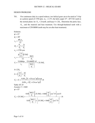
- 1. SECTION 12 – HELICAL GEARS Page 1 of 14 DESIGN PROBLEMS 701. For continuous duty in a speed reducer, two helical gears are to be rated at 7.4 hp at a pinion speed of 1750 rpm; 75.2≈wm ; the helix angle 15o ; 20o F.D. teeth in the normal plane; let 21=pN teeth, and keep pDb 2< . Determine the pitch, face, gN , and the material and heat treatment. Use through-hardened teeth with a maximum of 250 BHM (teeth may be cut after heat treatment). Solution: o 15=ψ o n 20=φ 12 pp m nD v π = dd p p PP N D 21 == rpmnp 1750= ( ) d d m P P v 9621 12 1750 21 = = π ( )( ) d d m t P P v hp F 38.25 9621 4.7000,33000,33 = == pDb 2≤ dd PP b 4221 2 = = ( ) ( ) lb CbFv CbFv FF tm tm td 2 1 2 2 cos05.0 coscos05.0 ψ ψψ ++ + += Table AT 25 Assume 1660=C o 15=ψ lb P P P P P P PF d d d d d d dd 2 1 2 2 15cos 42 166038.25 9621 05.0 15cos15cos 42 166038.25 9621 05.0 38.25 ++ + +=
- 2. SECTION 12 – HELICAL GEARS Page 2 of 14 lb P P P P P P PF d d d d d d dd 2 1 65050 38.25 481 65050 38.25 465 38.25 ++ + += For continuous service: dw FF ≥ ψ2 cos gp w QKbD F = ( ) 467.1 175.2 75.22 1 2 = + = + = g g m m Q Table At 26, Bhn = 250 Sum of BHN = 500, o n 20=φ 131=gK ( )( ) 22 670,181 15cos 131467.12142 ddd w PPP F = = dw FF ≥ By trial and error method dP dF wF 7 3967 3708 6 4758 5046 use 6=dP in P D d p 5.3 6 2121 === in P b d 7 6 4242 === fpm P v d m 1604 6 96219621 === Fig. AF 19, permissible error = 0.0018 in Fig. AF 20 Use carefully cut gears, 6=dP Error = 0.001 in is o.k. For material Strength df s PK sbY F ψcos =
- 3. SECTION 12 – HELICAL GEARS Page 3 of 14 23 15cos 21 cos 33 === ψ p ep N N Table AT 24, Load near middle 23=epN , FDn o 20=φ 565.0=Y assume 0.2=fK dsfs FNF = assume 0.2=sfN ( )( ) ( )( ) ( )( )24758 62 15cos565.07 = s psis 892,29= use 3 u n s s = ( ) psisu 676,89892,293 == Use C1050, OQT 1100 F, ksisu 122= , 250248 <=BHN Ans. 6=dP inb 7= ( )( ) 582175.2 === pwg NmN Material. C1050, OQT 1100 F 703. A pair of helical gears, subjected to heavy shock loading, is to transmit 50 hp at 1750 rpm of the pinion.; 25.4=gm ; o 15=ψ ; minimum . 4 3 4 inDp = ; continuous service, 24 hr/day; 20o F.D. teeth in the normal plane, carefully cut; through- hardened to a maximum BHN = 350. Decide upon the pitch, face width, material and its treatment. Solution: ( )( ) fpmvm 2176 12 175075.4 == π ( )( ) ( ) lb v hp F m t 758 2176 50000,33000,33 === Dynamic load: ( ) ( ) lb CbFv CbFv FF tm tm td 2 1 2 2 cos05.0 coscos05.0 ψ ψψ ++ + += Fig. AF 19, fpmvm 2176= Permissible error = 0.0014 in
- 4. SECTION 12 – HELICAL GEARS Page 4 of 14 Use carefully cut gears, ine 001.0= , 5=dP as standard Table AT 25, Steel and steel, 20o FD 1660=C ( )( ) ( ) ( ) lb b b Fd 2 1 2 2 15cos1660758217605.0 15cos15cos1660758217605.0 758 ++ + += ( ) ( ) lb b b Fd 2 1 8.15487588.108 8.15487581.105 758 ++ + += Wear load: ψ2 cos gp w QKbD F = ( ) 619.1 125.4 25.42 1 2 = + = + = g g m m Q Table At 26, 20o FD, Sum of BHN =2(350)=700 270=gK ( )( )( ) b b Fw 2225 15cos 270619.175.4 2 == dw FF ≥ , .69.4 tan 2 2min in P Pb d a === ψ π By trial and error method b dF wF 5 5203 11125 6 5811 13350 use inb 5= Material: Strength: dfdnf s PK sbY PK sbY F ψcos == ψ3 cos p ep N N = ( )( ) 22375.45 === pdp DPN 25 15cos 22 3 ==epN Table AT 24, Load near middle
- 5. SECTION 12 – HELICAL GEARS Page 5 of 14 25=epN , FDn o 20=φ 580.0=Y assume 7.1=fK ( )( ) ( )( ) s s Fs 32955.0 57.1 15cos580.05 == dsfs FNF = for 24 hr/day service, heavy shock loading 75.1=sfN ( )( )520375.132955.0 =s psis 629,27= use 3 u n s s = ( ) psisu 887,82629,273 == Table AT 9 Use 4150, OQT 1200 F, ksisu 159= , 350331<=BHN Ans. 5=dP inb 5= Material. 4150, OQT 1200 F 705. Design the teeth for two herringbone gears for a single-reduction speed reducer with 80.3=wm . The capacity is 36 hp at 3000 rpm of the pinion; o 30=ψ ; F.D. teeth with o 20=nφ . Since space is at a premium, the initial design is for 15=pN teeth and carburized teeth of AISI 8620; preferably pDb 2< . Solution: dd p p PP N D 15 == pDb 2≈ d p P Db 30 2 == 12 pp m nD v π = ( ) d d m P P v 781,11 12 3000 15 = = π
- 6. SECTION 12 – HELICAL GEARS Page 6 of 14 ( )( ) d d m t P P v hp F 101 781,11 36000,33000,33 = == Dynamic load ( ) ( ) lb CbFv CbFv FF tm tm td 2 1 2 2 cos05.0 coscos05.0 ψ ψψ ++ + += o n 20=φ o 30=ψ Assume 1660=C , Table AT 25, 20o FD lb P P P P P P PF d d d d d d dd 2 1 2 2 30cos 30 1660101 781,11 05.0 30cos30cos 30 1660101 781,11 05.0 101 ++ + += lb P P P P P P PF d d d d d d dd 2 1 350,37 101 589 350,37 101 510 101 ++ + += Wear load ψ2 cos gp w QKbD F = ( ) 583.1 180.3 80.32 1 2 = + = + = g g m m Q For AISI 8620, carburized, 20o FD 750=gK for 1010 cycles ( )( ) 22 350,712 30cos 750583.11530 ddd w PPP F = = By trial and error, dw FF ≥ dP dF wF 5 4433 28,494 4 5454 44,522 6 3817 19,788 8 3173 11,130 9 3008 8794 For carefully cut gears, 001.0=e fpmv 1400max = (Fig. AF 9)
- 7. SECTION 12 – HELICAL GEARS Page 7 of 14 dP d m P v 781,11 = 5 2356.2 4 1963.5 6 1683 8 1473 9 1309 fpm use 9=dP lbFd 3008= dw FlbF >= 5794 in P b d 3.3 9 3030 === use inb 0.3= To check for strength dfdnf s PK sbY PK sbY F ψcos == ψ3 cos p ep N N = 15=pN 23 30cos 15 3 ==epN Table AT 24, Load near middle 23=epN , FDn o 20=φ 565.0=Y assume 7.1=fK 8620, SOQT 450, ksisu 167= 3 u n s s = 5.83 2 167 2 === u n s s ( )( )( ) ( )( ) ( )lbFlbF ds 30088011 97.1 30cos565.00.3500,83 =>== Designed Data: 9=dP inb 0.3= 15=pN ( )( ) 57158.3 === pwg NmN
- 8. SECTION 12 – HELICAL GEARS Page 8 of 14 in P N D d p p 67.1 9 15 === in P N D d g g 33.6 9 57 === CHECK PROBLEMS 707. The data for a pair of carefully cut gears are: 5=dnP , o 20=nφ , o 12=ψ , .5.3 inb = , 18=pN , 108=gN teeth; pinion turns 1750 rpm. Materials: pinion, SAE 4150, OQT to BHN = 350; gear, SAE 3150, OQT to BHN = 300. Operation is with moderate shock for 8 to 10 hr./day. What horsepower may be transmitted continuously? Solution: d p p P N D = ( ) 89.415cos5cos === ψdnd PP inDp 681.3 89.4 18 == Wear load ψ2 cos gp w QKbD F = .5.3 inb = ( ) 7143.1 10818 10822 = + = + = gp g NN N Q Table AT 26, o 20=nφ Sum of BHN = 350 + 300 = 650 233=gK ( )( )( )( ) lbFw 5379 12cos 2337143.1681.35.3 2 == Strength of gear lb PK sbY F dnf s = For gear: SAE 3150, OQT to BHN = 300 ksisu 151= ( ) ksiss un 5.751515.05.0 === 116 12cos 108 cos 33 === ψ g eg N N
- 9. SECTION 12 – HELICAL GEARS Page 9 of 14 Table AT 24, Load near middle, o 20=nφ 763.0=Y ( )( ) 6.57763.05.75 ==Ysn For pinion: SAE 4150, OQT to BHN = 350 ( ) ksiBHNsu 1753505.05.0 === ( ) ksiss un 5.871755.05.0 === 19 12cos 18 cos 33 === ψ p ep N N Table AT 24, Load near middle, o 20=nφ 534.0=Y ( )( ) 7.46534.05.87 ==Ysn Therefore use pinion as weak Assume 7.1=fK ( )( )( ) ( )( ) lbFs 240,19 57.1 534.05.3500,87 == For moderate shock, 8 to 10 hr./day Use 5.1=sfN dsfs FNF ≥ dF5.1240,19 = lbFd 827,12≤ Therefore use lbFF wd 5379== ( ) ( ) lb CbFv CbFv FF tm tm td 2 1 2 2 cos05.0 coscos05.0 ψ ψψ ++ + += Fig. AF 20, carefully cut gears, 5=dnP , ine 001.0= Table AT 25, steel and steel, 20o FD 1660=C ( )( ) fpm nD v pp m 1686 12 1750681.3 12 === ππ ( ) ( )[ ] ( ) ( )[ ] lb F F FF t t td 2 1 2 2 12cos5.31660168605.0 12cos12cos5.31660168605.0 ++ + += [ ] [ ] lb F F FF t t td 5379 55593.84 555946.82 2 1 = ++ + += Trial and error lbFt 1800= ( )( ) hp vF hp mt 92 000,33 16861800 000,33 ===
- 10. SECTION 12 – HELICAL GEARS Page 10 of 14 708. Two helical gears are used in a single reduction speed reducer rated at 27.4 hp at a motor speed of 1750 rpm; continuous duty. The rating allows an occasional 100 % momentary overload. The pinion has 33 teeth. 10=dnP , .2 inb = , o 20=nφ , o 20=ψ , 82.2=wm . For both gears, the teeth are carefully cut from SAE 1045 with BHN = 180. Compute (a) the dynamic load, (b) the endurance strength; estimate 7.1=fK . Also decide whether or not the 100 % overload is damaging. (c) Are these teeth suitable for continuous service? If they are not suitable suggest a cure. (The gears are already cut.) Solution: d p p P N D = ( ) 66.915cos10cos === ψdnd PP inDp 42.3 66.9 33 == ( )( ) fpm nD v pp m 1567 12 175042.3 12 === ππ ( ) lb v hp F m t 577 1567 4.27000,33000,33 === (a) Dynamic load ( ) ( ) lb CbFv CbFv FF tm tm td 2 1 2 2 cos05.0 coscos05.0 ψ ψψ ++ + += Fig. AF 20, carefully cut gears, 10=dnP , ine 001.0= Table AT 25, steel and steel, 20o FD 1660=C inb 2= ( ) ( )[ ] ( ) ( )[ ] lbFd 2578 15cos21660577156705.0 15cos15cos21660577156705.0 577 2 1 2 2 = ++ + += (b) Endurance strength lb PK sbY F dnf s = For SAE 1045, BHN = 180 ( ) ksiBHNsu 901805.05.0 === ( ) ksiss un 45905.05.0 === 37 15cos 33 cos 33 === ψ p ep N N Table AT 24, Load near middle, o 20=nφ
- 11. SECTION 12 – HELICAL GEARS Page 11 of 14 645.0=Y 7.1=fK ( )( )( ) ( )( ) lb PK sbY F dnf s 3415 107.1 645.02000,45 === For 100 % overload ( ) lbFt 11545772 == ( ) ( ) lb CbFv CbFv FF tm tm td 2 1 2 2 cos05.0 coscos05.0 ψ ψψ ++ + += ( ) ( )[ ] ( ) ( )[ ] lbFd 3475 15cos216601154156705.0 15cos15cos216601154156705.0 1154 2 1 2 2 = ++ + += Since ds FF ≈ , 100 % overload is not damaging (c) ψ2 cos gp w QKbD F = .2 inb = ( ) 476.1 182.2 82.22 1 2 = + = + = w w m m Q Table AT 26, o 20=nφ Sum of BHN = 2(180) = 360 5.62=gK ( )( )( )( ) ( )lbFlbF dw 2578676 15cos 5.62476.142.32 2 =<== Therefore not suitable for continuous service. Cure: Through hardened teeth For Bhn ( ) 2385.62 676 2578 ==gK min Bhn = 0.5(650) = 325 709. Two helical gears are used in a speed reducer whose input is 100 hp at 1200 rpm, from an internal combustion engine. Both gears are made of SAE 4140, with the pinion heat treated to a BHN 363 – 415, and the gear to 321 – 363; let the teeth be F.D.; 20o pressure angle in the normal plane; carefully cut; helix angle o 15=ψ ; 22=pN , 68=gN teeth; 5=dP , inb 4= . Calculate the dynamic load, the endurance strength load, and the limiting wear load for the teeth. Should these gears have long life if they operate continuously? (Data courtesy of the Twin Disc Clutch Co.) Solution:
- 12. SECTION 12 – HELICAL GEARS Page 12 of 14 in P N D d p p 4.4 5 22 === ( )( ) fpm nD v pp m 1382 12 12004.4 12 === ππ ( ) lb v hp F m t 2388 1382 100000,33000,33 === Dynamic load ( ) ( ) lb CbFv CbFv FF tm tm td 2 1 2 2 cos05.0 coscos05.0 ψ ψψ ++ + += Fig. AF 20, carefully cut gears, 5=dnP , ine 001.0= Table AT 25, steel and steel, 20o FD 1660=C inb 4= ( ) ( )[ ] ( ) ( )[ ] lbFd 5930 15cos416602388138205.0 15cos15cos416602388138205.0 2388 2 1 2 2 = ++ + += Endurance strength load lb PK sbY F df s ψcos = Assume 7.1=fK Pinion ( ) ksiBHNsn 75.9036325.025.0 === 25 15cos 22 cos 33 === ψ p ep N N Table AT 24, Load near middle, o 20=nφ 580.0=Y ( )( )( ) ( )( ) lb PK sbY F df s 925,23 57.1 15cos580.04750,90cos === ψ Gear ( ) ksiBHNsn 25.8032125.025.0 === 75 15cos 68 cos 33 === ψ p ep N N Table AT 24, Load near middle, o 20=nφ 735.0=Y ( )( )( ) ( )( ) lb PK sbY F df s 811,26 57.1 15cos735.04250,80cos === ψ use lbFs 925,23=
- 13. SECTION 12 – HELICAL GEARS Page 13 of 14 Limiting Wear Load ψ2 cos gp w QKbD F = Table AT 26, o 20=nφ Sum of BHN = 684 to 778 use 700 270=gK ( ) 511.1 6822 6822 = + = + = gp g NN N Q ( )( )( )( ) lbFw 7696 15cos 270511.14.44 2 == Since ( ) ( )lbFlbF dw 59307696 =>= these gears have long life if they operate continuously. CROSSED HELICAL 710. Helical gears are to connect two shafts that are at right angles ( 201 =N , 402 =N , 10=dnP , o 4521 ==ψψ ). Determine the center distance. Solution: 11 11 1 cos cos ψ ψπ DP P D N dn cn == ( )( ) 45cos1020 1D= inD 83.21 = 222 cosψDPN dn= ( )( ) 45cos1040 2D= inD 66.52 = ( ) ( ) inDDC 25.466.583.22 1 212 1 =+=+= 712. Two shafts that are at right angles are to be connected by helical gears. A tentative design is to use 201 =N , 602 =N , 10=dnP , and a center distance of 6 in. What must be the helix angles? Solution: o 9021 =+=Σ ψψ 1 1 1 cosψdnP N D = 2 2 2 cosψdnP N D = ( )212 1 DDC +=
- 14. SECTION 12 – HELICAL GEARS Page 14 of 14 2 2 1 1 coscos 2 ψψ dndn P N P N C += ( ) 21 cos10 60 cos10 20 62 ψψ += 21 cos 6 cos 2 12 ψψ += 21 cos 3 cos 1 6 ψψ += By trial and error method 11 sin 3 cos 1 6 ψψ += o 5.391 =ψ o 5.502 =ψ - end -