Downloaded 11 times
![408 Solutions Manual • Instructor’s Solution Manual to Accompany Mechanical Engineering Design
RH shoe: Fx = 500 sin 30° = 250 lbf, Fy = 500 cos 30° = 433 lbf
Eqs. (16-8): A =
1
2
sin2 θ
120◦
0◦
= 0.375, B =
θ
2
− 1
4
sin 2θ
2π/3 rad
0
= 1.264
Eqs. (16-9): Rx = 111.4(1.5)(6)
1
[0.375 − 0.28(1.264)] − 250 = −229 lbf
Ry = 111.4(1.5)(6)
1
[1.264 + 0.28(0.375)] − 433 = 940 lbf
R = [(−229)2 + (940)2]1/2 = 967 lbf Ans.
LH shoe: Fx = 250 lbf, Fy = 433 lbf
Eqs. (16-10): Rx = 57.9(1.5)(6)
1
[0.375 + 0.28(1.264)] − 250 = 130 lbf
Ry = 57.9(1.5)(6)
1
[1.264 − 0.28(0.375)] − 433 = 171 lbf
R = [(130)2 + (171)2]1/2 = 215 lbf Ans.
16-2 θ1 = 15°, θ2 = 105°, θa = 90°, sin θa = 1, a = 5 in
Eq. (16-2): Mf = 0.28pa(1.5)(6)
1
105°
15°
sin θ(6 − 5 cos θ) dθ = 13.06pa
Eq. (16-3): MN = pa(1.5)(6)(5)
1
105°
15°
sin2 θ dθ = 46.59pa
c = 2(5 cos 30°) = 8.66 in
Eq. (16-4): F = 46.59pa − 13.06pa
8.66
= 3.872pa
RH shoe:
pa = 500/3.872 = 129.1 psi on RH shoe for cw rotation Ans.
Eq. (16-6): TR = 0.28(129.1)(1.5)(62)(cos 15° − cos 105°)
1
= 2391 lbf · in
LH shoe:
500 = 46.59pa + 13.06pa
8.66
⇒ pa = 72.59 psi on LH shoe for ccw rotation Ans.
TL = 0.28(72.59)(1.5)(62)(cos 15° − cos 105°)
1
= 1344 lbf · in
Ttotal = 2391 + 1344 = 3735 lbf · in Ans.
Comparing this result with that of Prob. 16-1, a 2.7% reduction in torque is achieved by
using 25% less braking material.](https://image.slidesharecdn.com/shi20396ch16-140910223321-phpapp02/85/Shi20396-ch16-2-320.jpg)
![Chapter 16 409
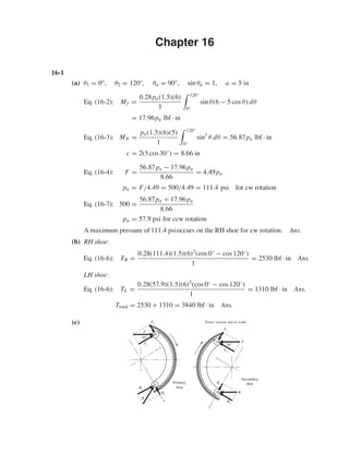
16-3 Given: θ1 = 0°, θ2 = 120°, θa = 90°, sin θa = 1, a = R = 90 mm, f = 0.30,
F = 1000 N = 1 kN, r = 280/2 = 140 mm, counter-clockwise rotation.
LH shoe:
Mf = f pabr
sin θa
r(1 − cos θ2) − a
2
sin2 θ2
= 0.30pa(0.030)(0.140)
1
0.140(1 − cos 120◦) − 0.090
2
sin2 120°
= 0.000 222pa N · m
MN = pabra
sin θa
θ2
2
− 1
4
sin 2θ2
= pa(0.030)(0.140)(0.090)
1
120°
2
π
180
− 1
4
sin 2(120°)
= 4.777(10−4) pa N · m
c = 2r cos
180◦ − θ2
2
= 2(0.090) cos 30◦ = 0.155 88 m
F = 1 = pa
4.777(10−4) − 2.22(10−4)
0.155 88
= 1.64(10−3) pa
pa = 1/1.64(10−3) = 610 kPa
TL = f pabr2(cos θ1 − cos θ2)
sin θa
= 0.30(610)(103)(0.030)(0.1402)
1
[1 − (−0.5)]
= 161.4 N · m Ans.
RH shoe:
Mf = 2.22(10−4) pa N · m
MN = 4.77(10−4) pa N · m
c = 0.155 88 m
F = 1 = pa
4.77(10−4) + 2.22(10−4)
0.155 88
= 4.49(10−3) pa
pa = 1
4.49(10−3)
= 222.8 kPa Ans.
TR = (222.8/610)(161.4) = 59.0 N · m Ans.](https://image.slidesharecdn.com/shi20396ch16-140910223321-phpapp02/85/Shi20396-ch16-3-320.jpg)
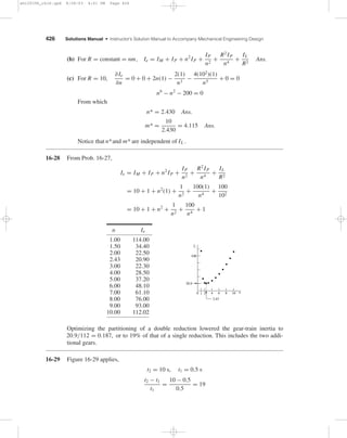
(0.200)
sin 75°
(0.0775) = 289 N · m
From Eq. (16-3),
MN = pabra
sin θa
B = [(10)6](0.075)(0.200)(0.150)
sin 75°
(0.528) = 1230 N · m
Finally, using Eq. (16-4), we have
F = MN − Mf
c
= 1230 − 289
165
= 5.70 kN Ans.
(b) Use Eq. (16-6) for the primary shoe.
T = f pabr2(cos θ1 − cos θ2)
sin θa
= 0.24[(10)6](0.075)(0.200)2(cos 10° − cos 75°)
sin 75°
= 541 N · m
For the secondary shoe, we must first find pa.
Substituting
MN = 1230
106 pa and Mf = 289
106 pa into Eq. (16-7),
5.70 = (1230/106) pa + (289/106) pa
165
, solving gives pa = 619(10)3 Pa
Then
T = 0.24[0.619(10)6](0.075)(0.200)2(cos 10° − cos 75°)
sin 75°
= 335 N · m
so the braking capacity is Ttotal = 2(541) + 2(335) = 1750 N · m Ans.](https://image.slidesharecdn.com/shi20396ch16-140910223321-phpapp02/85/Shi20396-ch16-4-320.jpg)
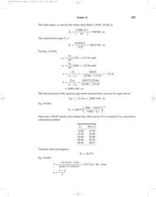
−3 − 5.70 = −0.658 kN
Ry = pabr
sin θa
(B + f C) − Fy
= (106)(0.075)(0.200)
sin 75°
[0.528 + 0.24(0.4514)](10)−3 − 0 = 9.88 kN
Secondary shoes:
Rx = pabr
sin θa
(C + f B) − Fx
= [0.619(10)6](0.075)(0.200)
sin 75°
[0.4514 + 0.24(0.528)](10)−3 − 5.70
= −0.143 kN
Ry = pabr
sin θa
(B − f C) − Fy
= [0.619(10)6](0.075)(0.200)
sin 75°
[0.528 − 0.24(0.4514)](10)−3 − 0
= 4.03 kN
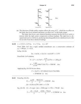
Note from figure that +y for secondary shoe is opposite to
+y for primary shoe.
Combining horizontal and vertical components,
RH = −0.658 − 0.143 = −0.801 kN
RV = 9.88 − 4.03 = 5.85 kN
R =
(0.801)2 + (5.85)2
= 5.90 kN Ans.
16-5 Preliminaries: θ1 = 45° − tan−1(150/200) = 8.13°, θ2 = 98.13°
θa = 90°, a = [(150)2 + (200)2]1/2 = 250 mm
Eq. (16-8): A = 1
2
sin2 θ
98.13°
8.13°
= 0.480
Let C =
θ2
θ1
sin θ dθ = −
cos θ
98.13°
8.13°
= 1.1314
y
y
x
x
R
RV
RH](https://image.slidesharecdn.com/shi20396ch16-140910223321-phpapp02/85/Shi20396-ch16-5-320.jpg)
![412 Solutions Manual • Instructor’s Solution Manual to Accompany Mechanical Engineering Design
Eq. (16-2):
Mf = f pabr
sin θa
(rC − aA) = 0.25pa(0.030)(0.150)
sin 90°
[0.15(1.1314) − 0.25(0.48)]
= 5.59(10−5) pa N · m
Eq. (16-8): B =
θ
2
− 1
4
sin 2θ
98.13π/180 rad
8.13π/180 rad
= 0.925
Eq. (16-3): MN = pabra
sin θa
B = pa(0.030)(0.150)(0.250)
1
(0.925)
= 1.0406(10−3) pa N · m
Using F = (MN − Mf )/c, we obtain
400 = 104.06 − 5.59
0.5(105)
pa or pa = 203 kPa Ans.
T = f pabr2C
sin θa
= 0.25(203)(103)(0.030)(0.150)2
1
(1.1314)
= 38.76 N · m Ans.
16-6 For +3ˆσ
f :
f = ¯ f + 3ˆσ
f = 0.25 + 3(0.025) = 0.325
Mf = 5.59(10−5) pa
0.325
0.25
= 7.267(10−5) pa
Eq. (16-4):
400 = 104.06 − 7.267
105(0.500)
pa
pa = 207 kPa
207
203
T = 38.75
0.325
0.25
= 51.4 N · m Ans.
Similarly, for −3ˆσ
f :
f = ¯ f − 3ˆσ
f = 0.25 − 3(0.025) = 0.175
Mf = 3.913(10−5) pa
pa = 200 kPa
T = 26.7 N · m Ans.
16-7 Preliminaries: θ2 = 180° − 30° − tan−1(3/12) = 136°, θ1 = 20° − tan−1(3/12) = 6°,
θa = 90◦, a = [(3)2 + (12)2]1/2 = 12.37 in, r = 10 in, f = 0.30, b = 2 in.
Eq. (16-2): Mf = 0.30(150)(2)(10)
sin 90°
136◦
6°
sin θ(10 − 12.37 cos θ) dθ
= 12 800 lbf · in](https://image.slidesharecdn.com/shi20396ch16-140910223321-phpapp02/85/Shi20396-ch16-6-320.jpg)
![Chapter 16 413
Eq. (16-3): MN = 150(2)(10)(12.37)
sin 90°
136°
6°
sin2 θ dθ = 53 300 lbf · in
LH shoe:
cL = 12 + 12 + 4 = 28 in
Now note that Mf is cw and MN is ccw. Thus,
FL = 53 300 − 12 800
28
= 1446 lbf
FL 1446 lbf
14
Eq. (16-6): TL = 0.30(150)(2)(10)2(cos 6° − cos 136°)
sin 90°
= 15 420 lbf · in
RH shoe:
pa
150
MN = 53 300
= 355.3pa, Mf = 12 800
pa
150
= 85.3pa
On this shoe, both MN and Mf are ccw.
Also cR = (24 − 2 tan 14°) cos 14° = 22.8 in
Fact = FL sin 14° = 361 lbf Ans.
FR = FL/ cos 14° = 1491 lbf
Thus 1491 = 355.3 + 85.3
22.8
pa ⇒ pa = 77.2 psi
Then TR = 0.30(77.2)(2)(10)2(cos 6° − cos 136°)
sin 90°
= 7940 lbf · in
Ttotal = 15 420 + 7940 = 23 400 lbf · in Ans.
16-8
Mf = 2
θ2
0
( f dN)(a cos θ − r ) where dN = pbr dθ
= 2 f pbr
θ2
0
(a cos θ − r ) dθ = 0
From which
a
θ2
0
cos θ dθ = r
θ2
0
dθ
a = rθ2
sin θ2
= r (60°)(π/180)
sin 60°
= 1.209r
Eq. (16-15)
a = 4r sin 60°
2(60)(π/180) + sin[2(60)]
= 1.170r
16
Fact 361 lbf
FR 1491 lbf 4](https://image.slidesharecdn.com/shi20396ch16-140910223321-phpapp02/85/Shi20396-ch16-7-320.jpg)
![Chapter 16 417
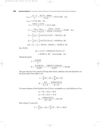
Eq. (16-14): P2 = P1 exp(− f φ) = 1680 exp(−0.942) = 655 lbf
T = (P1 − P2)
D
2
= (1680 − 655)
16
2
= 8200 lbf · in Ans.
H = Tn
63 025
= 8200(200)
63 025
= 26.0 hp Ans.
P = 3P1
10
= 3(1680)
10
= 504 lbf Ans.
(b)
Net torque on drum due to brake band:
T = TP1
− TP2
= 13 440 − 5240
= 8200 lbf · in
The radial load on the bearing pair is 1803 lbf. If the bearing is straddle mounted with
the drum at center span, the bearing radial load is 1803/2 = 901 lbf.
(c) Eq. (16-22):
p = 2P
bD
p|θ=0° = 2P1
3(16)
= 2(1680)
3(16)
= 70 psi Ans.
As it should be
p|θ=270° = 2P2
3(16)
= 2(655)
3(16)
= 27.3 psi Ans.
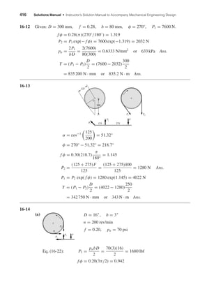
16-15 Given: φ=270°, b=2.125 in, f =0.20, T =150 lbf · ft, D=8.25 in, c2 = 2.25 in
Notice that the pivoting rocker is not located on the vertical centerline of the drum.
(a) To have the band tighten for ccw rotation, it is necessary to have c1 c2 . When fric-tion
is fully developed,
P1
P2
= exp( f φ) = exp[0.2(3π/2)] = 2.566
1803 lbf
8200 lbf¥in
1680 lbf
655 lbf
Force of shaft on the drum: 1680 and 655 lbf
TP1
= 1680(8) = 13 440 lbf · in
TP2
= 655(8) = 5240 lbf · in
1680 lbf
1803 lbf
655 lbf
13,440 lbf•in 5240 lbf•in
Force of belt on the drum:
R = (16802 + 6552)1/2 = 1803 lbf
1680 lbf
655 lbf](https://image.slidesharecdn.com/shi20396ch16-140910223321-phpapp02/85/Shi20396-ch16-11-320.jpg)
![418 Solutions Manual • Instructor’s Solution Manual to Accompany Mechanical Engineering Design
If friction is not fully developed
P1/P2 ≤ exp( f φ)
To help visualize what is going on let’s add a force W parallel to P1, at a lever arm of
c3 . Now sum moments about the rocker pivot.
M = 0 = c3W + c1P1 − c2P2
From which
W = c2P2 − c1P1
c3
The device is self locking for ccw rotation if W is no longer needed, that is, W ≤ 0.
It follows from the equation above
P1
P2
≥ c2
c1
When friction is fully developed
2.566 = 2.25/c1
c1 = 2.25
2.566
= 0.877 in
When P1/P2 is less than 2.566, friction is not fully developed. Suppose P1/P2 = 2.25,
then
c1 = 2.25
2.25
= 1 in
We don’t want to be at the point of slip, and we need the band to tighten.
c2
P1/P2
≤ c1 ≤ c2
When the developed friction is very small, P1/P2 →1 and c1 →c2 Ans.
(b) Rocker has c1 = 1 in
P1
P2
= c2
c1
= 2.25
1
= 2.25
f = ln(P1/P2)
φ
= ln 2.25
3π/2
= 0.172
Friction is not fully developed, no slip.
T = (P1 − P2)
D
2
= P2
P1
P2
D
2
− 1
Solve for P2
P2 = 2T
[(P1/P2) − 1]D
= 2(150)(12)
(2.25 − 1)(8.25)
= 349 lbf
P1 = 2.25P2 = 2.25(349) = 785 lbf
p = 2P1
bD
= 2(785)
2.125(8.25)
= 89.6 psi Ans.](https://image.slidesharecdn.com/shi20396ch16-140910223321-phpapp02/85/Shi20396-ch16-12-320.jpg)
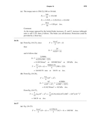
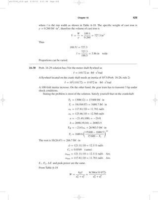
 = 7173 lbf · in
(c) The table indicates a maximum within the range:
3 ≤ d ≤ 5 in
(d) Consider: 0.45 ≤ d
D
≤ 0.80](https://image.slidesharecdn.com/shi20396ch16-140910223321-phpapp02/85/Shi20396-ch16-14-320.jpg)
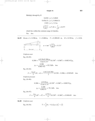
![(D/2)3 − (d/2)3
[(D/2)2 − (d/2)2D]
= 2(D/2)3(1 − (d/D)3)
3(D/2)2[1 − (d/D)2]D
= 1
3
1 − (d/D)3
1 − (d/D)2
O.K. Ans.
16-21 ω = 2πn/60 = 2π 500/60 = 52.4 rad/s
T = H
ω
= 2(103)
52.4
= 38.2 N· m
Key:
F = T
r
= 38.2
12
= 3.18 kN
Average shear stress in key is
τ = 3.18(103)
6(40)
= 13.2 MPa Ans.
Average bearing stress is
σb = − F
Ab
= −3.18(103)
3(40)
= −26.5 MPa Ans.
Let one jaw carry the entire load.
rav = 1
2
26
2
+ 45
2
= 17.75 mm
F = T
rav
= 38.2
17.75
= 2.15 kN
shi20396_ch16.qxd 8/28/03 4:01 PM Page 422](https://image.slidesharecdn.com/shi20396ch16-140910223321-phpapp02/85/Shi20396-ch16-17-320.jpg)
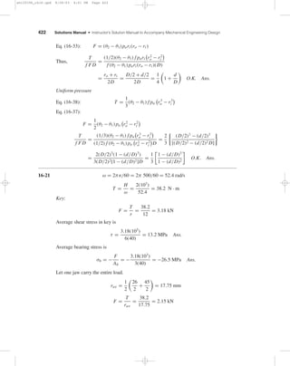
![Chapter 16 423
The bearing and shear stress estimates are
σb =
−2.15(103)
10(22.5 − 13)
= −22.6 MPa Ans.
τ = 2.15(103)
10[0.25π(17.75)2]
= 0.869 MPa Ans.
16-22 ω1 = 2πn/60 = 2π(1800)/60 = 188.5 rad/s
ω2 = 0
From Eq. (16-51),
I1 I2
I1 + I2
= T t1
ω1 − ω2
= 320(8.3)
188.5 − 0
= 14.09 N · m · s2
Eq. (16-52):
E = 14.09
188.52
2
(10−3) = 250 kJ
Eq. (16-55):
T = E
Cpm
= 250(103)
500(18)
= 27.8◦C Ans.
16-23
n = n1 + n2
2
= 260 + 240
2
= 250 rev/min
Cs = 260 − 240
250
= 0.08 Ans.
ω = 2π(250)/60 = 26.18 rad/s
I = E2 − E1
Csω2
= 5000(12)
0.08(26.18)2
= 1094 lbf · in · s2
Ix = m
8
d2
o
+ d2
i
= W
8g
d2
o
+ d2
i
W = 8gI
d2
o
+ d2
i
= 8(386)(1094)
602 + 562
= 502 lbf
w = 0.260 lbf/in3 for cast iron
V = W
w
= 502
0.260
= 1931 in3
Also, V = πt
4
d2
o
− d2
i
= πt
4
602 − 562
= 364t in3
Equating the expressions for volume and solving for t,
t = 1931
364
= 5.3 in Ans.
shi20396_ch16.qxd 8/28/03 4:01 PM Page 423](https://image.slidesharecdn.com/shi20396ch16-140910223321-phpapp02/85/Shi20396-ch16-18-320.jpg)

The document contains detailed calculations related to forces and pressures in mechanical systems, including the analysis of braking components. It provides various equations used to determine load and torque on brake shoes in different rotational scenarios, comparing results across varying parameters. The results highlight the effects of adjustments in braking material on torque reduction and include specific numerical outcomes for various conditions.


![電路學 - [第六章] 二階RLC電路](https://cdn.slidesharecdn.com/ss_thumbnails/circuitch6-150613063009-lva1-app6892-thumbnail.jpg?width=640&height=640&fit=bounds)

![RF Circuit Design - [Ch1-1] Sinusoidal Steady-state Analysis](https://cdn.slidesharecdn.com/ss_thumbnails/ch1-1-150613064348-lva1-app6891-thumbnail.jpg?width=640&height=640&fit=bounds)
![電路學 - [第四章] 儲能元件](https://cdn.slidesharecdn.com/ss_thumbnails/circuitch4-150613063008-lva1-app6891-thumbnail.jpg?width=640&height=640&fit=bounds)

![射頻電子 - [實驗第四章] 微波濾波器與射頻多工器設計](https://cdn.slidesharecdn.com/ss_thumbnails/e4-150613065110-lva1-app6892-thumbnail.jpg?width=640&height=640&fit=bounds)
![射頻電子 - [第一章] 知識回顧與通訊系統簡介](https://cdn.slidesharecdn.com/ss_thumbnails/ch1-150613065058-lva1-app6891-thumbnail.jpg?width=640&height=640&fit=bounds)