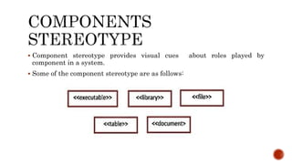
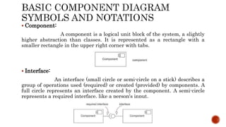
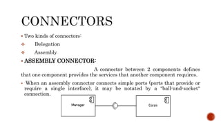
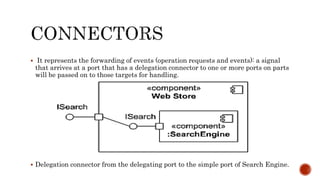
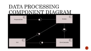
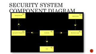
OOAD Presentation
GROUP
MEMBER
S
Abdul Manan
 (14-Arid-4641)
Muhammad Usama
 (14-Arid-4754)
 An UML diagram classification:
 Static
Use case diagram, Class diagram
 Dynamic
State diagram, Activity diagram, Sequence diagram, Collaboration
diagram
 Implementation
Component diagram, Deployment diagram
 UML components diagrams are
 Implementation diagrams: describe the different elements required for
implementing a system.
 A component diagram, also known as a UML component diagram,
describes the organization and wiring of the physical components in a
system.
 Component diagrams are often drawn to help model implementation
details and double-check that every aspect of the system's required
functions is covered by planned development.
 The purpose of a component diagram is to show the relationship between
different components in a system
 Component diagrams are used to visualize the static implementation view
of a system. Component diagrams are special type of UML diagrams used
for different purposes. These diagrams show the physical components of a
system.
 Component diagrams are very important from implementation
perspective.
 Component diagrams can be used to −
 Model the components of a system.
 Model the database schema.
 Model the executables of an application.
 Model the system's source code.
 A high-level, abstracted view of a component in UML can be modelled as:
 A rectangle with the component's name
 A rectangle with the component icon
 A rectangle with the stereotype text and/or icon
 Component stereotype provides visual cues about roles played by
component in a system.
 Some of the component stereotype are as follows:
 Component:
A component is a logical unit block of the system, a slightly
higher abstraction than classes. It is represented as a rectangle with a
smaller rectangle in the upper right corner with tabs.
 Interface:
An interface (small circle or semi-circle on a stick) describes a
group of operations used (required) or created (provided) by components. A
full circle represents an interface created by the component. A semi-circle
represents a required interface, like a person's input.
 Dependencies:
Shows that one part of your system depends on another.
Dependencies are represented by dashed lines linking one component (or
element) to another.
 Port:
Symbolized with a small square, Specifies a distinct interaction point
Between that component and its environment
Between that component and its internal parts
 The subsystem classifier is a specialized version of a component classifier.
Because of this, the subsystem notation element inherits all the same rules as
the component notation element.
 The only difference is that a subsystem notation element has the keyword of
subsystem instead of component.
 Two kinds of connectors:
 Delegation
 Assembly
 ASSEMBLY CONNECTOR:
A connector between 2 components defines
that one component provides the services that another component requires.
 When an assembly connector connects simple ports (ports that provide or
require a single interface), it may be notated by a "ball-and-socket"
connection.
 Assembly:
The semantics for an assembly connector :
 Are that signals travel along an instance of a connector originating in a
required port and delivered to a provided port.
 An assembly connector is a connector between two or more ports on parts that
defines that one or more parts provide the services that other parts use.
 DELEGATION:
Links the external contract of a component to the internal
realization. Delegate connector wires the internal workings of the system to the
outside world.
 A Delegate connector defines the internal assembly of a component's external
Ports and Interfaces, on a Component diagram.
 A port may delegate to a set of ports on subordinate components.
 Is used to model the hierarchical decomposition.
 Message and signal flow will occur between the connected ports.
 It represents the forwarding of events (operation requests and events): a signal
that arrives at a port that has a delegation connector to one or more ports on parts
will be passed on to those targets for handling.
 Delegation connector from the delegating port to the simple port of Search Engine.
Component diagram
Component diagram
Component diagram

Component diagram

  • 1.
  • 2.
  • 3.
     An UMLdiagram classification:  Static Use case diagram, Class diagram  Dynamic State diagram, Activity diagram, Sequence diagram, Collaboration diagram  Implementation Component diagram, Deployment diagram  UML components diagrams are  Implementation diagrams: describe the different elements required for implementing a system.
  • 4.
     A componentdiagram, also known as a UML component diagram, describes the organization and wiring of the physical components in a system.  Component diagrams are often drawn to help model implementation details and double-check that every aspect of the system's required functions is covered by planned development.  The purpose of a component diagram is to show the relationship between different components in a system
  • 6.
     Component diagramsare used to visualize the static implementation view of a system. Component diagrams are special type of UML diagrams used for different purposes. These diagrams show the physical components of a system.  Component diagrams are very important from implementation perspective.  Component diagrams can be used to −  Model the components of a system.  Model the database schema.  Model the executables of an application.  Model the system's source code.
  • 7.
     A high-level,abstracted view of a component in UML can be modelled as:  A rectangle with the component's name  A rectangle with the component icon  A rectangle with the stereotype text and/or icon
  • 8.
     Component stereotypeprovides visual cues about roles played by component in a system.  Some of the component stereotype are as follows:
  • 9.
     Component: A componentis a logical unit block of the system, a slightly higher abstraction than classes. It is represented as a rectangle with a smaller rectangle in the upper right corner with tabs.  Interface: An interface (small circle or semi-circle on a stick) describes a group of operations used (required) or created (provided) by components. A full circle represents an interface created by the component. A semi-circle represents a required interface, like a person's input.
  • 10.
     Dependencies: Shows thatone part of your system depends on another. Dependencies are represented by dashed lines linking one component (or element) to another.  Port: Symbolized with a small square, Specifies a distinct interaction point Between that component and its environment Between that component and its internal parts
  • 11.
     The subsystemclassifier is a specialized version of a component classifier. Because of this, the subsystem notation element inherits all the same rules as the component notation element.  The only difference is that a subsystem notation element has the keyword of subsystem instead of component.
  • 12.
     Two kindsof connectors:  Delegation  Assembly  ASSEMBLY CONNECTOR: A connector between 2 components defines that one component provides the services that another component requires.  When an assembly connector connects simple ports (ports that provide or require a single interface), it may be notated by a "ball-and-socket" connection.
  • 13.
     Assembly: The semanticsfor an assembly connector :  Are that signals travel along an instance of a connector originating in a required port and delivered to a provided port.  An assembly connector is a connector between two or more ports on parts that defines that one or more parts provide the services that other parts use.
  • 14.
     DELEGATION: Links theexternal contract of a component to the internal realization. Delegate connector wires the internal workings of the system to the outside world.  A Delegate connector defines the internal assembly of a component's external Ports and Interfaces, on a Component diagram.  A port may delegate to a set of ports on subordinate components.  Is used to model the hierarchical decomposition.  Message and signal flow will occur between the connected ports.
  • 15.
     It representsthe forwarding of events (operation requests and events): a signal that arrives at a port that has a delegation connector to one or more ports on parts will be passed on to those targets for handling.  Delegation connector from the delegating port to the simple port of Search Engine.