Downloaded 1,670 times

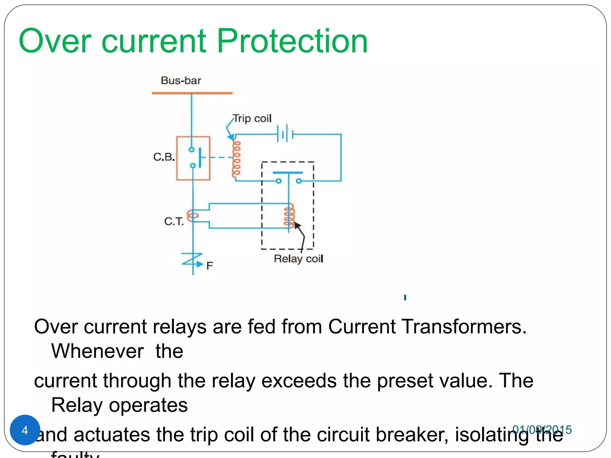
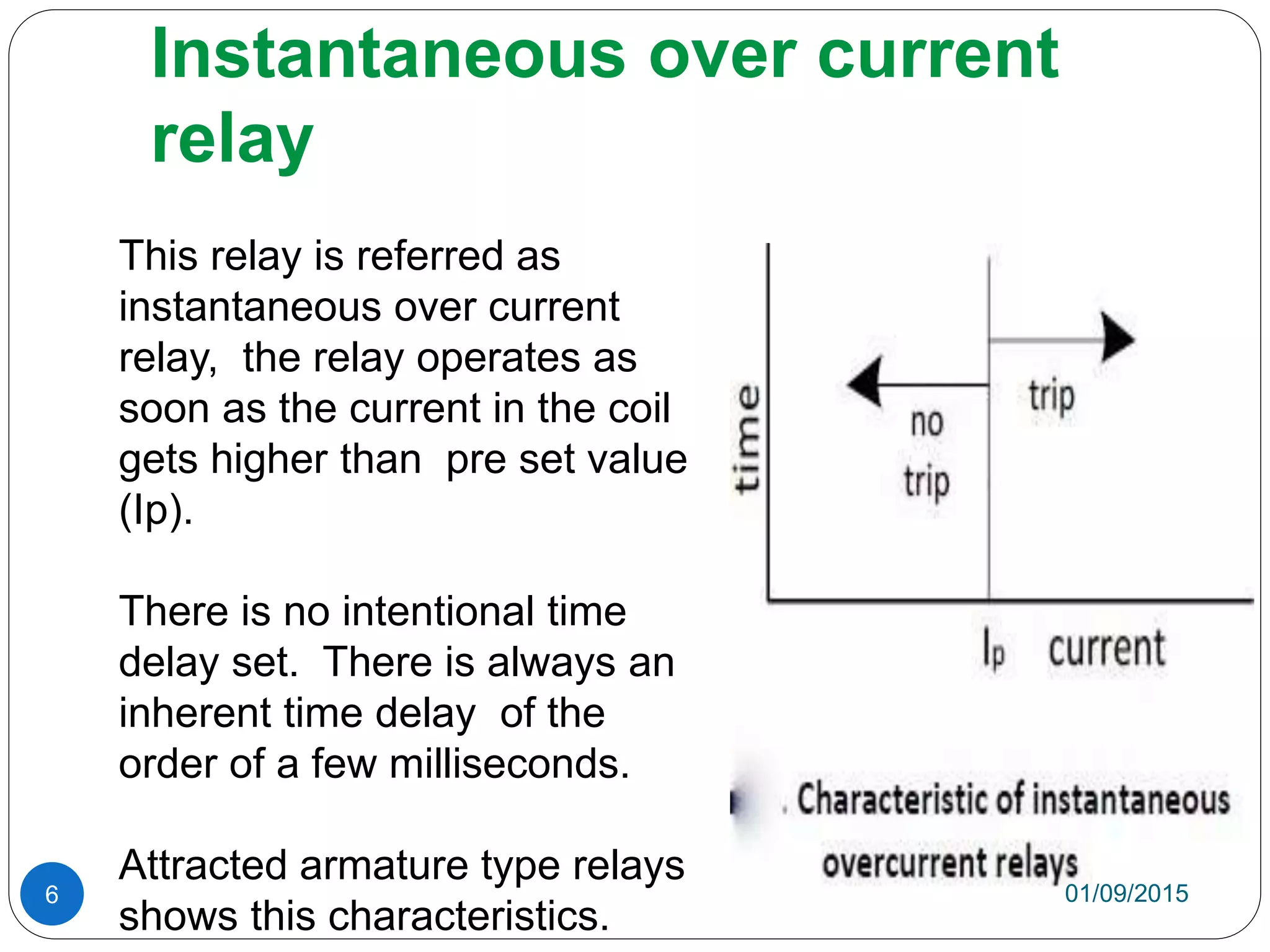
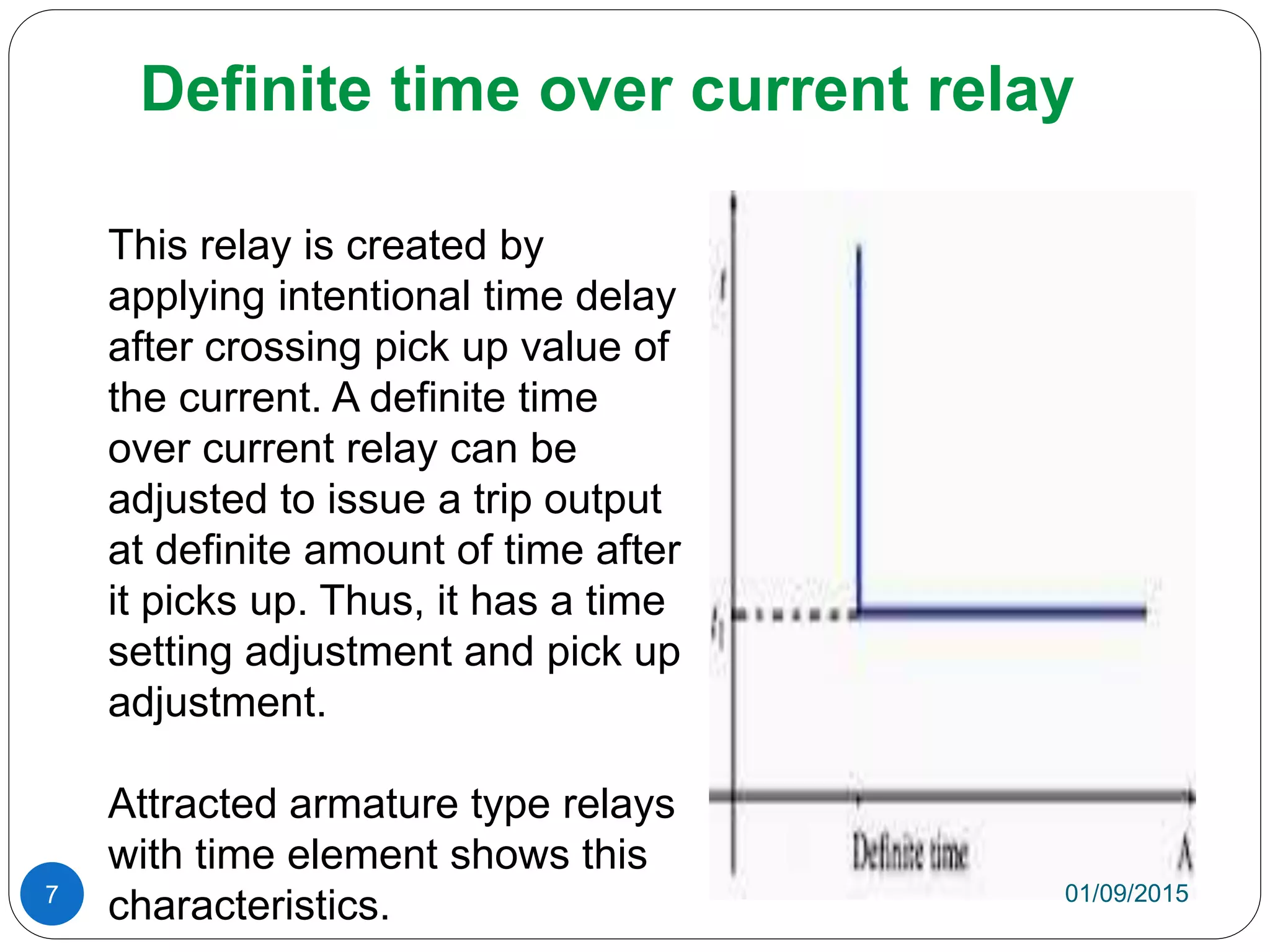

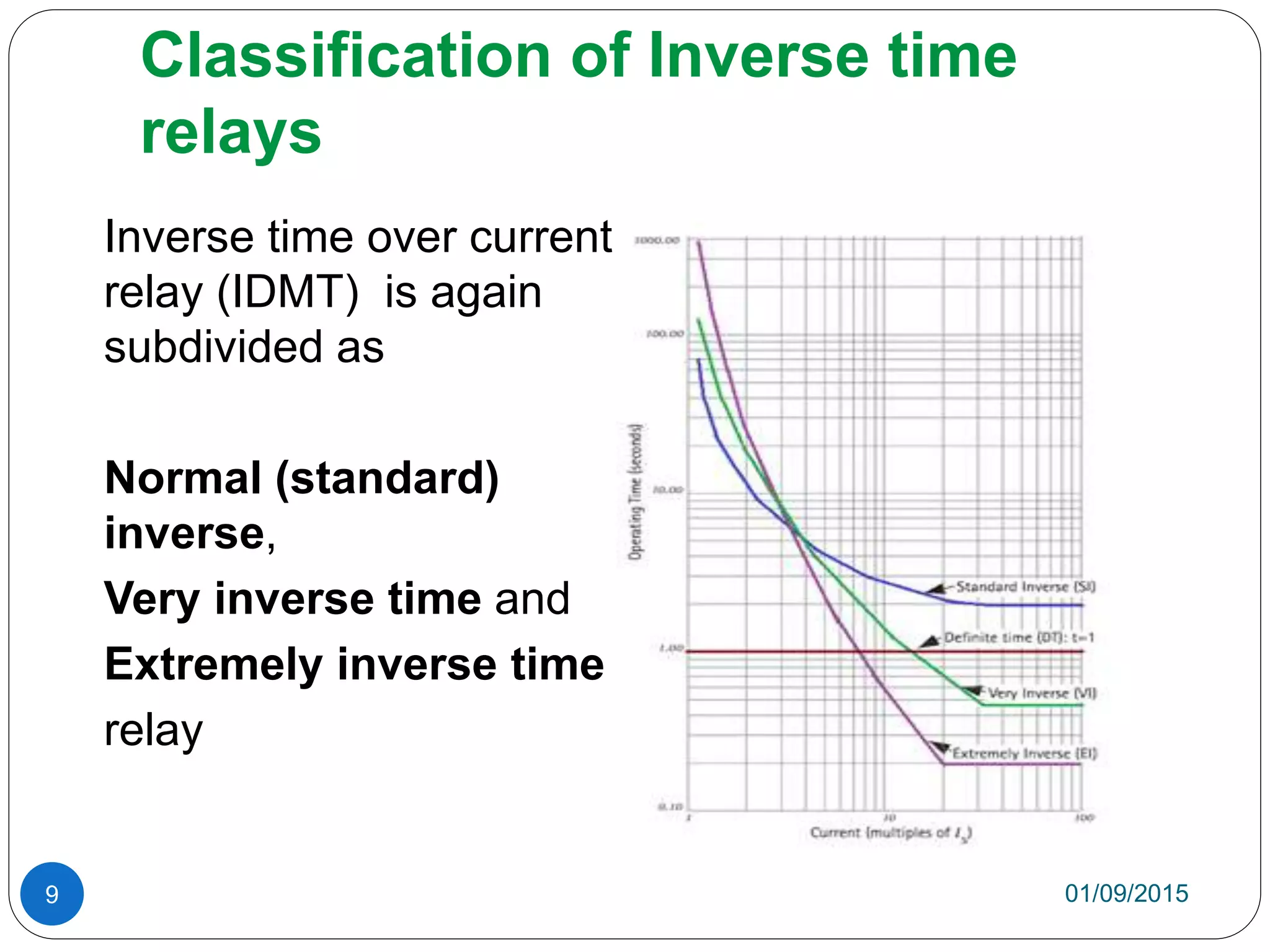
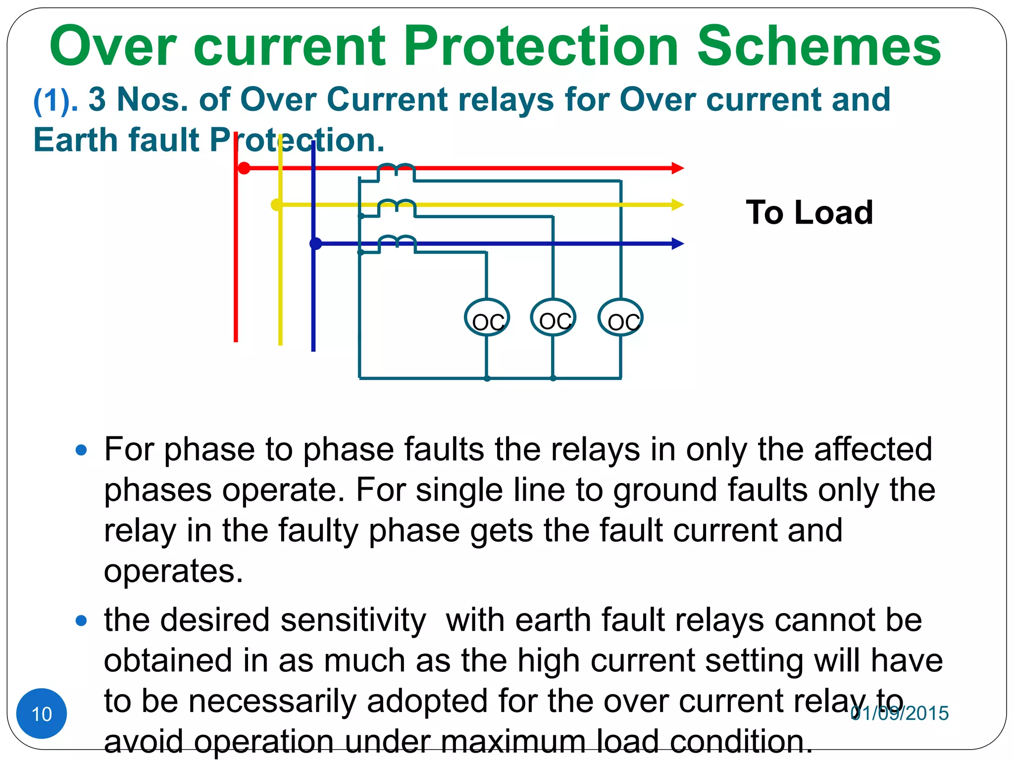
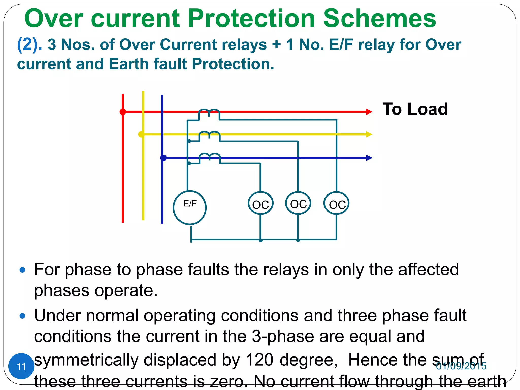
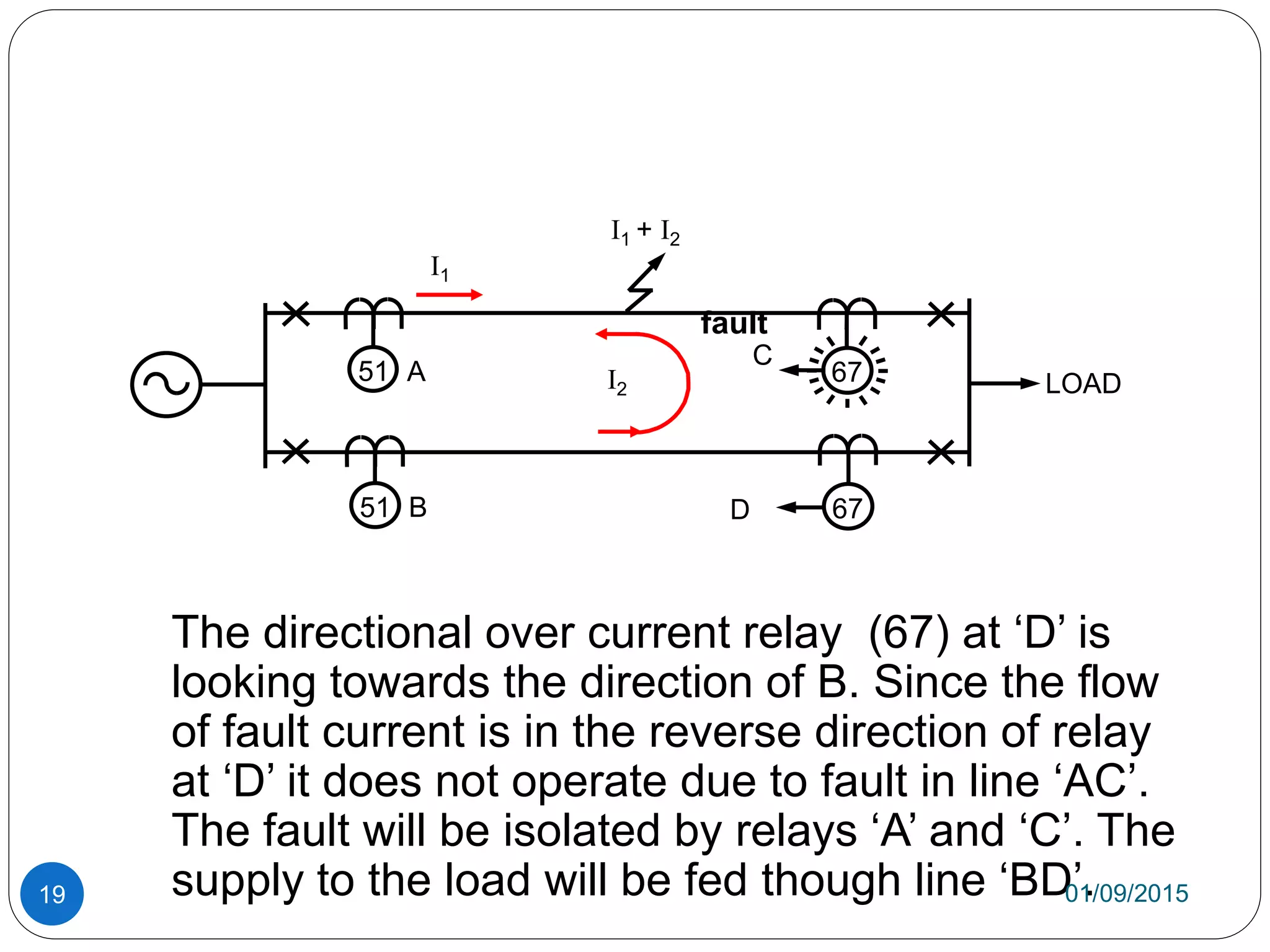


1) Over current occurs when electric current exceeds intended levels, potentially causing equipment damage from excess heat. It can be caused by short circuits, overloading, design flaws, or ground faults. 2) Over current relays contain a current coil. During normal operation, the magnetic effect is insufficient to trigger the relay. During over currents, the increased magnetic effect overcomes the restraint, moving the contact to isolate the circuit. 3) Over current relays come in instantaneous, definite time, and inverse time variations depending on their time of operation. Inverse time relays isolate faults faster for more severe over currents.


![protection of transmission lines[distance relay protection scheme]](https://cdn.slidesharecdn.com/ss_thumbnails/os-exe3-23-may2011-sr-i-776s21tr-lineprotection-120425095503-phpapp02-thumbnail.jpg?width=640&height=640&fit=bounds)


