Download as PDF, PPTX
![10
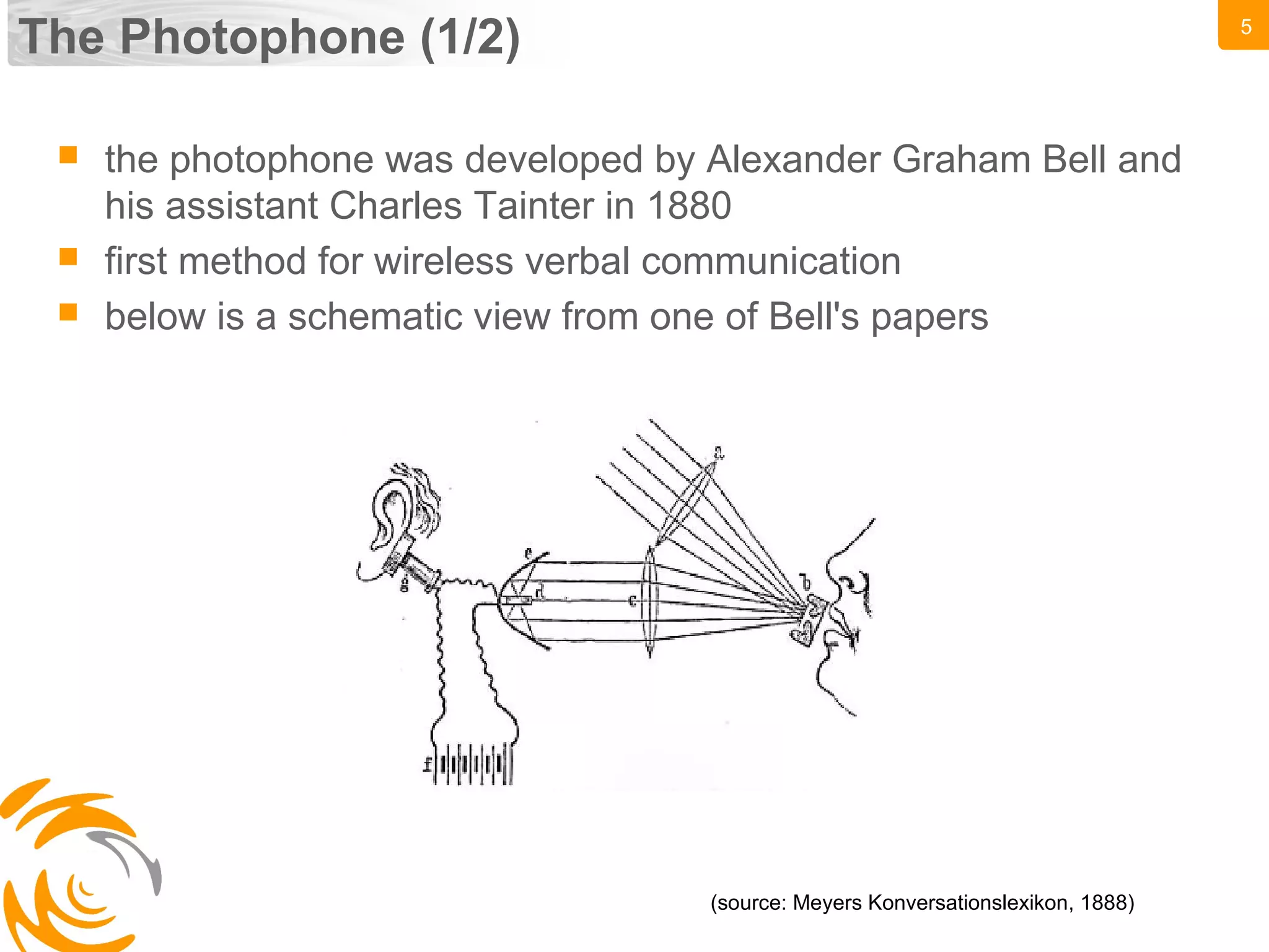
Technology (2/3)
schematic view of the entire process of transmitting and
receiving data
(source: based on a schematic view shown in [1])](https://image.slidesharecdn.com/2010-06-29pohlmann-visiblelightcommunication-101026200204-phpapp02/75/visible-light-communication-10-2048.jpg)
![12
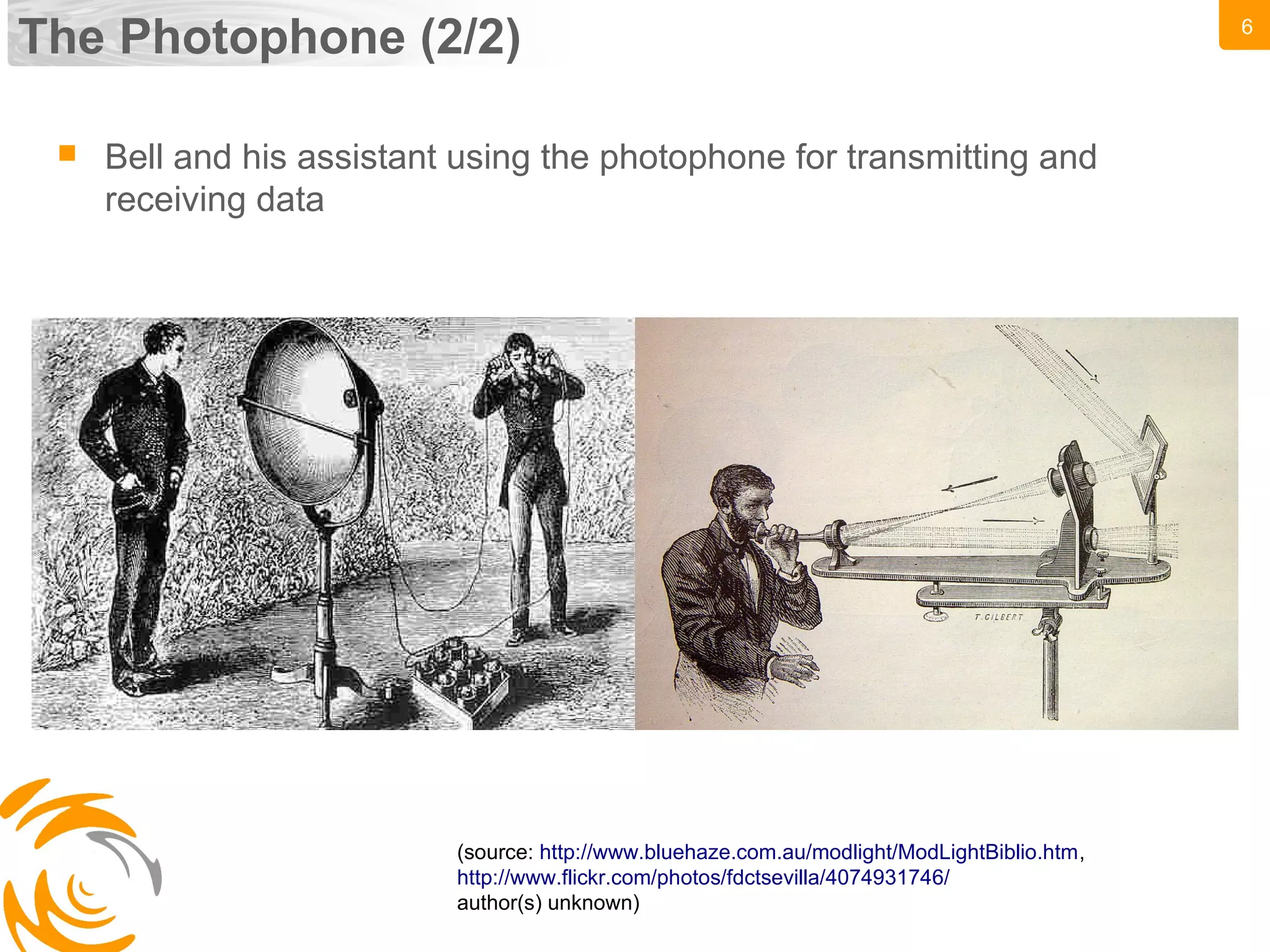
Comparison to other wireless technologies
(source: IEEE VLC Tutorial http://www.ieee802.org/15/pub/TG7.html [2])](https://image.slidesharecdn.com/2010-06-29pohlmann-visiblelightcommunication-101026200204-phpapp02/75/visible-light-communication-12-2048.jpg)
![19
JEITA CP-1222
according to Shinichiro Haruyama (vice chairman of the VLCC)
the following recommendations are proposed by JEITA CP-
1222 (see [3] for more details):
SC frequency: 28.8 kHz
transmission rate: 4.8 kbps
modulation: SC-4PPM (chosen to avoid flickering)
cyclic redundancy checks (CRC) for error detection/correction](https://image.slidesharecdn.com/2010-06-29pohlmann-visiblelightcommunication-101026200204-phpapp02/75/visible-light-communication-19-2048.jpg)
![23
Providing an uplink
VLC is a natural broadcast medium
sending back information to the source is sometimes desired
there are three major approaches to providing an uplink to the
camera (as discussed in [4]):
co-locating the light source with a VLC receiver
- advantage: data can be sent back
- drawback: sending light back is costly (energy-wise)
using a retro-reflector to return incident light
- advantage: data can be sent back from several sources in parallel
- drawback: uplink data rates are rather low using this approach
fitting the light source with a RF or IR receiver
- advantage: data can be sent back fast
- drawback: no VLC is used, all disadvantages of not using VLC (EM-
interference etc.)](https://image.slidesharecdn.com/2010-06-29pohlmann-visiblelightcommunication-101026200204-phpapp02/75/visible-light-communication-23-2048.jpg)
![25
References
H.Sugiyama, S.Haruyama, M.Nakagawa. Experimental investigation
of modulation method for visible-light communications [1]
IEEE VLC tutorial (http://www.ieee802.org/15/pub/TG7.html) [2]
Japan's Visible Light Communications Consortium and Its
Standardization Activities (Shinichiro Haruyama, Ph.D) [3]
Visible Light Communications: challenges and possibilities: Dominic
C. O’Brien et al. [4]](https://image.slidesharecdn.com/2010-06-29pohlmann-visiblelightcommunication-101026200204-phpapp02/75/visible-light-communication-25-2048.jpg)

Visible light communication (VLC) uses visible light spectrum to transmit data wirelessly. It has several advantages over traditional wireless technologies like WiFi, including no interference with other devices, safety in medical settings, and ubiquitous availability with rising LED usage. Early experiments with VLC date back to 1880 with Alexander Graham Bell's photophone. Modern standardization efforts aim to avoid fragmentation and promote applications like indoor localization, smart retail, and vehicle-to-vehicle communication. Key challenges include increasing data rates and providing bidirectional communication capabilities. VLC remains an emerging technology but shows promise for a variety of uses.