SlideShare a Scribd company logo
The German user manual is the original document 
User Manual NF11ST3xxAC 
SOLTRK 
Control unit for PV tracking systems
Produced by SMA Solar Technology AG 
NF11ST3xxAC User manual 
Contents 
1 Notes on this Document .................................................................................. 5 
1.1 Target Group ........................................................................................................ 5 
1.2 Validity ................................................................................................................. 5 
1.3 Symbols Used ...................................................................................................... 6 
2 SOLTRK ......................................................................................................... 7 
2.1 Application and Function ....................................................................................... 7 
2.2 Functions ............................................................................................................. 8 
2.3 Scope of Delivery .................................................................................................. 9 
2.4 Identification ......................................................................................................... 9 
2.4.1 Name Plate ................................................................................................................9 
2.4.2 Firmware Version .......................................................................................................9 
3 Safety Instructions ......................................................................................... 10 
4 Installation .................................................................................................... 11 
5 Connection ................................................................................................... 12 
5.1 Wiring Diagram and Cable Feed-Throughs .......................................................... 12 
5.2 Connecting the Limit Switches and Drives ........................................................... 13 
5.3 Connecting the Communication Device to the Inverter .......................................... 14 
5.3.1 Wiring Diagram (Inverter to SOLTRK) ..................................................................... 14 
5.4 Connecting the communication to the Sunny WebBox .......................................... 17 
5.4.1 Cabling Notes ......................................................................................................... 17 
5.4.2 Jumper Functions ................................................................................................... 17 
5.4.3 Wiring Diagram Sunny WebBox to SOLTRK ........................................................... 18 
5.4.4 Wiring Diagram Sunny WebBox with RS485 Power Injector .................................... 21 
5.5 Connecting another SOLTRK .............................................................................. 23 
5.6 Connecting the Power Supply and Overdrive Line ................................................ 27 
5.7 Grounding Connection ........................................................................................ 28 
6 Commissioning ............................................................................................. 29 
6.1 Switching on the Power Supply ........................................................................... 29
Produced by SMA Solar Technology AG 
User manual NF11ST3xxAC 
6.2 System Test in Manual Mode .............................................................................. 31 
6.2.1 Checking the Installation ......................................................................................... 31 
6.3 Configuring the Sunny WebBox and SOLTRK Parameters ................................... 34 
6.3.1 Setting the Time, Date, Time Zone and Synchronisation .......................................... 34 
6.3.2 Detecting the SOLTRK using the Sunny WebBox .................................................... 34 
6.3.3 Assigning the detected SOLTRK devices ................................................................ 35 
6.3.4 Determining and Setting the Geographic Location Data ........................................... 35 
6.4 Calibrating the Travelling Range using the Manual Control Unit ............................ 38 
6.4.1 Selecting the Calibration Mode ................................................................................ 38 
6.4.2 Performing South Calibration .................................................................................. 39 
6.4.3 Performing Sun Calibration ..................................................................................... 40 
6.4.4 Performing Quick Calibration ................................................................................... 41 
6.5 Starting Automatic Operation and Overdrive Function Test ................................... 42 
7 Tracking Function .......................................................................................... 43 
7.1 Movement of the Module Surface in “Auto” Operating Mode ............................... 44 
7.1.1 Motor Test .............................................................................................................. 44 
7.1.2 Reference Run ........................................................................................................ 44 
7.1.3 Standby .................................................................................................................. 45 
7.1.4 Tracking .................................................................................................................. 45 
7.2 Operation using Remote Operating Commands ................................................... 46 
7.3 track_back:Special Function to Prevent Shadowing Effects .................................. 47 
8 Maintenance and Cleaning ............................................................................ 48 
8.1 Maintenance ....................................................................................................... 48 
8.2 Cleaning ............................................................................................................. 48 
9 Decommissioning .......................................................................................... 49 
9.1 Disassembly ....................................................................................................... 49 
9.2 Packaging for Shipment ...................................................................................... 49 
9.3 Disposal ............................................................................................................. 49 
10 Technical Data .............................................................................................. 50 
11 Appendix ....................................................................................................... 51
Produced by SMA Solar Technology AG 
NF11ST3xxAC User manual 
11.1 LEDs ............................................................................................................. 51 
11.2 Channel List ................................................................................................... 53 
11.2.1 Spot Values ............................................................................................................ 53 
11.2.2 Parameters ............................................................................................................. 57 
11.3 Remote Control Mode (Remote Operation) ...................................................... 58 
11.4 Errors ............................................................................................................. 60 
11.4.1 Clearing Permanent Errors (LED) ............................................................................ 66 
11.5 Using the Manual Control Unit ........................................................................ 67 
11.5.1 Summary of Manual Control Unit Commands .......................................................... 68 
11.6 Cabling Recommendations ............................................................................. 69 
11.6.1 Communication ....................................................................................................... 69 
11.6.2 Power supply .......................................................................................................... 70 
12 Accessories ...................................................................................................... 71 
13 Contact ............................................................................................................ 72
Produced by SMA Solar Technology AG 
User manual NF11ST3xxAC 5 
1 Notes on this Document 
1.1 Target Group 
This document is a user manual aimed at installers and operators. It contains a de- scription on the installation, commissioning and operation of the SOLTRK. 
The appendix includes summary tables on 
• the LED functions 
• the channel lists 
• error codes and descriptions 
• a description of commands for remote operation 
• the manual control functions 
The activities described in this document are only to be performed by qualified electri- cians. They are marked with a danger notice. 
1.2 Validity 
This user manual applies to SOLTRK firmware version 1.6 and Sunny WebBox software version 1.42 and above. 
This user manual only describes the functional units of the SOLTRK control unit. It is not a user manual for the sonnen_system nor does it replace the user manual for the sonnen_system.
Produced by SMA Solar Technology AG 
6 NF11ST3xxAC User manual 
1.3 Symbols Used 
The following hazard categories are used in this document. 
DANGER! 
The term Danger indicates a hazard which, if ignored, can lead to fatal injury 
WARNING! 
The term Warning indicates a hazard which, if ignored, can lead to seri- ous injury or death. 
CAUTION! 
The term Caution indicates a hazard which, if ignored, can lead to injury. 
ATTENTION! 
The term Attention indicates a hazard which, if ignored, can lead to mate- rial damage 
Other symbols 
This symbol indicates a notice which, if ignored, will make the procedure or operation more difficult.
Produced by SMA Solar Technology AG 
User manual NF11ST3xxAC 7 
2 SOLTRK 
2.1 Application and Function 
SOLTRK is a control unit for PV tracking systems which determines the sun’s position using astronomic calculations and automatically aligns the surface of the photovoltaic modules towards the sun. Tracking is performed in two axes, namely horizontal (X-axis = azimuth) and vertical (Y-axis = elevation). 
The following parameters must be entered into the SOLTRK using an SMA “Sunny WebBox” data logger connected to the RS485 interface: 
• longitude and latitude of the location 
• current date and time 
Up to 50 units (SOLTRK and inverters) can be managed by one Sunny WebBox. The travelling range of the tracking system can be restricted to prevent or reduce reciprocal shadowing of the sonnen_system installations (track-back). 
The SOLTRK can be employed in locations at latitudes between 25 ° and 65 ° north. The longitude of the location can lie between –180 ° and +180 °.
Produced by SMA Solar Technology AG 
8 NF11ST3xxAC User manual 
2.2 Functions 
SOLTRK functions 
• Automatic tracking of the sonnen_system in the horizontal and vertical axes by calculating the position of the sun based on the longitude/latitude of the location, the date and the time. 
• Controlling the elevation and azimuth drives and analysing the pulse signals from the rotary sensors. 
• Error monitoring during setup and tracking operation. 
• Optional connection of an “overdrive voltage” (overdrive), which enables the sonnen_system to move into a safe horizontal position, for example during a storm, independently of the SOLTRK control processor. 
• Reduced reciprocal shadowing of the sonnen_systems by using the Sunny Web- Box user interface to restrict the travelling range. 
Operation 
• Via the Sunny WebBox user interface or via manual control (only during commis- sioning and maintenance). 
Indication of the operating modes 
• The operating mode is indicated by the LEDs on the front of the SOLTRK. 
Remote maintenance / remote operation 
• The Sunny WebBox user interface can be used to configure, read and, if neces- sary, control or reset the SOLTRK. This allows efficient remote maintenance from any Internet connection, providing the Sunny WebBox is connected to the Internet. If an Internet connection is not available, direct Ethernet access to the Sunny WebBox is required in order to administrate the system. 
Deployment location 
• The SOLTRK can be deployed in locations situated between 25 ° and 65 ° lati- tude north and –180 ° to +180 ° longitude. 
Power supply 
• 24 V DC connection. (Maximum power consumption 5 A per sonnen_system). 
RS485 communication 
• To Sunny WebBox (software version 1.42 or higher) and inverter
Produced by SMA Solar Technology AG 
User manual NF11ST3xxAC 9 
2.3 Scope of Delivery 
SOLTRK 
2.4 Identification 
2.4.1 Name Plate 
You can identify the SOLTRK from its name plate (see figure to the right). The name plate is located on the right side of the SOLTRK housing. 
2.4.2 Firmware Version 
The firmware version can be displayed on the Sunny WebBox once it has successfully detected the SOLTRK. The firmware version is displayed as a channel (see section 11.2 „Channel List“ on page 53). 
Hardware version of the SOLTRK
Produced by SMA Solar Technology AG 
10 NF11ST3xxAC User manual 
3 Safety Instructions 
SOLTRK is a single-channel system. This means that the SOLTRK could provoke invol- untary movements if a hardware or software error occurs. Therefore, pay particular attention to the following safety instructions. 
CAUTION! Risk of injury or material damage. 
Unintended movements of the sonnen_system could result in injury or ma- terial damage. 
• Remove all voltages from the SOLTRK before working on the son- nen_system. 
• No persons or objects should be within the turning and tilting range of the sonnen_system. Ensure that this includes the entire range of travel, even beyond the position of the limit switch. 
• During commissioning and maintenance, the SOLTRK may only be operated in manual mode and without the external overdrive fuse. 
• Users are responsible for their own actions during manual operation. 
• The user must verify that the control unit and system are working properly before changing to automatic operation.
Produced by SMA Solar Technology AG 
User manual NF11ST3xxAC 11 
4 Installation 
This section describes the installation of the SOLTRK on the mounting plate of the son- nen_system. 
1. Unscrew the cover on the SOLTRK. 
2. Use the screws provided to attach the SOLTRK to the sonnen_system mount- ing plate, as shown in the figure to the right. 
Please note that even if the cover has been correctly fitted, the SOLTRK housing only meets the specified protection degree (IP65) after all the ca- bles have been installed. Complete the installation procedure to ensure that no humidity can enter the unit.
Produced by SMA Solar Technology AG 
12 NF11ST3xxAC User manual 
5 Connection 
5.1 Wiring Diagram and Cable Feed-Throughs 
Wiring diagram 
Front view of SOLTRK showing cable feed-throughs
Produced by SMA Solar Technology AG 
User manual NF11ST3xxAC 13 
5.2 Connecting the Limit Switches and Drives 
1. Unscrew the appropriate cable screw connection to make the connection to the SOLTRK (see figure to the right). 
2. Thread the cable through the respective cable feed-through. 
3. Connect the numbered wires of the motor cables to the corresponding con- nections inside the SOLTRK (see figure below). The cables are connected 1:1. The polarity of the limit switch connections is arbitrary. 
The motor will be damaged if the polarity of the motor connections is in- correct. Carefully check the connections. 
4. Manually tighten the cable screw connections (1.8 Nm).
Produced by SMA Solar Technology AG 
14 NF11ST3xxAC User manual 
Inside view of SOLTRK, control and drive connections 
• Azimuth drive = horizontal adjustment (X-axis) 
• Elevation drive = vertical adjustment (Y-axis) 
5.3 Connecting the Communication Device to the Inverter 
Use the cables recommended in section 11.6 ”Cabling Recommendations” on page 69. 
5.3.1Wiring Diagram (Inverter to SOLTRK) 
WARNING! Danger of electrocution! 
High voltages are present inside the inverter which can lead to serious injury or even death if touched. 
• All work on the inverters may only be performed by qualified electri- cians! 
• Before making the connections, isolate the inverter as described in the inverter documentation. 
• Follow all the safety instructions given in the inverter documentation.
Produced by SMA Solar Technology AG 
User manual NF11ST3xxAC 15 
Connection in the Inverter 
1. Open the inverter as described in the inverter documentation. 
2. Remove all jumpers and termination resistors (depending on the type of in- verter) for termination or signal bias which may be in the inverter. Refer to the instructions in the documentation on the RS485 communication interface on how to perform this procedure. 
3. Connect the cable to the communication interface in the inverter as de- scribed in the documentation on the RS485 communication interface. Also refer to the poster “wiring principles RS485_sonnen_system”. 
4. Lay the cable securely, using suitable fastening materials. 
Connection in the SOLTRK 
5. Unscrew the SOLTRK cable screw connection which is shaded in the figure below. 
6. Pull the cable through the cable screw connection. 
7. Strip the cable shield inside the SOLTRK and connect the shield to the SOLTRK terminal (see figure below).
Produced by SMA Solar Technology AG 
16 NF11ST3xxAC User manual 
8. Connect the wires inside the SOLTRK to the “Sunny Boy” connection (see fig- ure below). 
9. Shorten unnecessary conductors back to the cable sheath to prevent short circuits occurring. 
10. Manually tighten the cable screw connection (1.8 Nm). 
11. Lay the cable securely, using suitable fastening materials.
Produced by SMA Solar Technology AG 
User manual NF11ST3xxAC 17 
5.4 Connecting the communication to the Sunny WebBox 
5.4.1 Cabling Notes 
The cable length and quality can adversely affect the signal quality. To achieve good results, observe the instructions in section 11.6 “Cabling Recommendations” on page 69. 
5.4.2 Jumper Functions 
Termination 
To ensure the signal quality of the RS485 communication bus, this must be terminated in the two devices at the end of the RS485 communication bus. 
Refer to the documentation for the end device on how to configure the termination resistor. 
Termination is limited to the two devices at the end of the RS485 communication bus. This is illustrated in the following figure: 
The following devices can be found at each of the two ends of the RS485 data bus and must be terminated accordingly: 
• SOLTRK + SOLTRK 
• SOLTRK + Sunny WebBox 
• SOLTRK + Sunny SensorBox 
• Sunny WebBox + Sunny SensorBox 
Also refer to the poster “wiring principles RS485_sonnen_system”.
Produced by SMA Solar Technology AG 
18 NF11ST3xxAC User manual 
Signal biasing 
To ensure the signal quality of the RS485 communication bus, a maximum of one bias must be connected in the RS485 communication bus. We recommend doing this with the Sunny WebBox. Please refer to the Sunny WebBox documentation. 
5.4.3Wiring Diagram Sunny WebBox to SOLTRK 
If an RS485 power injector is connected to your Sunny WebBox, refer to the details in section 5.4.4 “Wiring Diagram Sunny WebBox with RS485 Power Injector” on page 21. 
Connections in the Sunny WebBox 
1. Use the plug provided with the Sunny WebBox for the SMA-COM connection. 
2. Connect the cable to the Sunny Web- Box, as shown in the figure to the right. Refer to the table for details on the twisted pair cables.
Produced by SMA Solar Technology AG 
User manual NF11ST3xxAC 19 
3. Take note of the conductors' colour coding: 
WebBox 
“SMA COM” 
Conductor colour 
SOLTRK 
“RS485 IN” 
*2 
*D+ 
5 
GND 
*7 
*D- 
* The conductors 2 and 7 (D+ and D-) must be a twisted pair. 
4. If the Sunny WebBox is one of the two end points of the RS485 data bus, check that jumper J1A is mounted. 
5. Check that jumpers J1B and J1C are fitted to ensure signal biasing.
Produced by SMA Solar Technology AG 
20 NF11ST3xxAC User manual 
Connection in the SOLTRK 
6. Unscrew the SOLTRK cable screw connec- tion which is shaded in the figure to the right. 
7. Pull the cable through the cable screw connection. 
8. Strip the cable shield inside the SOLTRK and connect the shield to the SOLTRK ter- minal (see figure below). 
9. Connect the cable to the SOLTRK as shown in the figure above. Use the conductor colours you noted earlier. 
10.Manually tighten the cable screw connection (1.8 Nm).
Produced by SMA Solar Technology AG 
User manual NF11ST3xxAC 21 
5.4.4Wiring Diagram Sunny WebBox with RS485 Power Injector 
If a Sunny SensorBox is used in conjunction with your Sunny WebBox and the RS485 power injector is directly connected to the Sunny WebBox, connect the cabling as fol- lows. 
Sunny WebBox to RS485 Power Injector 
1. Pull out the RS485 Power Injector's power plug. 
2. Use the plug provided with the Sunny WebBox for the SMA-COM connection. 
3. Connect the RS485 Power Injector to the Sunny WebBox as shown in the figure to the right. Refer to the table for details on the twisted pair cables. 
4. Take note of the conductors' colour coding. 
WebBox 
SMA-COM 
Conductor colour 
RS485 Power Injector 
RS485 IN 
*2 
*D+ 
5 
GND 
*7 
*D- 
* The conductors 2 and 7 (D+ and D-) must be a twisted pair. 
5. If the Sunny WebBox is one of the two end points of the RS485 data bus, check that jumper J1A is mounted. 
6. Check that jumpers J1B and J1C are fitted to ensure signal biasing.
Produced by SMA Solar Technology AG 
22 NF11ST3xxAC User manual 
RS485 Power Injector to SOLTRK 
7. Unscrew the SOLTRK cable screw connection which is shaded in the fig- ure to the right. 
8. Pull the cable through the cable screw connection. 
9. Strip the cable shield inside the SOLTRK and connect the shield to the SOLTRK terminal (see figure below). 
10. Connect the RS485 power injector to the SOLTRK as shown in the figure above. Refer to the table for details on the twisted pair cables.
Produced by SMA Solar Technology AG 
User manual NF11ST3xxAC 23 
11. Take note of the conductors' colour coding. 
RS485 Power Injector 
RS485 + Power OUT 
Conductor colour 
SOLTRK 
RS485 IN 
*+12 V 
*+12 V 
*GND 
*GND 
*D+ 
*D+ 
*D- 
*D- 
*The +12 V and GND conductors, as well as the D+ und D- conductors must both be twisted pairs. 
12. Manually tighten the cable screw connection (1.8 Nm). 
5.5 Connecting another SOLTRK 
1. Remove the termination resistor on the “RS485 OUT” connection of the SOLTRK. 
2. Unscrew the SOLTRK cable screw con- nection which is shaded in the figure to the right (next to figure RS485 OUT). 
3. Pull the cable through the cable screw connection.
Produced by SMA Solar Technology AG 
24 NF11ST3xxAC User manual 
4. Strip the cable shield inside the SOLTRK and connect the shield to the SOLTRK terminal (see figure below). 
5. Connect the wires to the “RS485 OUT” connection of the SOLTRK as shown in the figure to the right. Refer to the ta- ble for details on the twisted pair ca- bles.
Produced by SMA Solar Technology AG 
User manual NF11ST3xxAC 25 
6. Take note of the conductors' colour coding: 
SOLTRK 
“RS485 OUT” 
Conductor colour 
SOLTRK 
“RS485 IN” 
*+12 V 
*+12 V 
*GND 
*GND 
*D+ 
*D+ 
*D- 
*D- 
* The +12 V and GND conductors, as well as the D+ und D- conductors must both be 
twisted pairs. 
7. Manually tighten the cable screw connection (1.8 Nm).
Produced by SMA Solar Technology AG 
26 NF11ST3xxAC User manual 
Additional SOLTRK 
8. Unscrew the cable screw connection which is shaded in the figure to the right (figure next to RS485 IN) on the next SOLTRK. 
9. Pull the cable through the cable screw connection. 
10. Strip the cable shield inside the SOLTRK and connect the shield to the SOLTRK terminal (see figure be- low). 
11. Connect the wires to the “RS485 IN” connection on the other SOLTRK as shown in the figure above. Use the conductor colours you noted earlier. 
12. Manually tighten the cable screw connection (1.8 Nm). 
13. Several SOLTRK can be connected together in the same manner. The termination resistor remains plugged into the RS485 data bus of the last SOLTRK (“RS485 OUT” connection). 
14. Lay the cables securely, using suitable fastening materials.
Produced by SMA Solar Technology AG 
User manual NF11ST3xxAC 27 
5.6 Connecting the Power Supply and Overdrive Line 
Connect the power supply (24 V DC) and overdrive as follows: 
1. Unscrew the appropriate cable screw connection to make the connection (see figure to the right, view of SOLTRK cable screw connections). 
2. Pull the cable through the cable screw connec- tion. 
3. Connect the power supply and overdrive line inside the SOLTRK as shown in the figure below. 
SOLTRK 
further SOLTRK
Produced by SMA Solar Technology AG 
28 NF11ST3xxAC User manual 
4. Take note of the conductors' colour coding: 
Connection 
Conductor colour 
Power supply 
+24 V 
GND 
Overdrive 
+ 
- 
5. Manually tighten the cable screw connections (3.5 Nm). 
5.7 Grounding Connection 
1. Fit a suitable ring cable lug to the earthing connection (see figure to the right) on the SOLTRK. 
2. Ground the SOLTRK to a suitable earthing star point.
Produced by SMA Solar Technology AG 
User manual NF11ST3xxAC 29 
6 Commissioning 
Commissioning of the SOLTRK occurs in five steps: 
• Switching on the power supply 
• System test in manual mode 
• Configuring the SOLTRK parameters 
• Calibrating the travelling range 
• Activating the automatic tracking function 
6.1 Switching on the Power Supply 
1. Unscrew the cover on the SOLTRK. 
2. Remove the overdrive fuse (see figure to the right) to prevent any accidental movement of the sonnen_system. 
3. Set the toggle switch in the SOLTRK to “MANUAL” (see figure to right). The SOLTRK switches to manual operation. 
4. Switch on the power supply. 
5. Check the LEDs on the SOLTRK: 
− The Power LED must glow green. 
− The Error LED must be off. 
− The Overdrive LED must flash (man- ual operation).
Produced by SMA Solar Technology AG 
30 NF11ST3xxAC User manual 
Connecting the manual control unit 
6. Attach the plug from the manual control unit into the corresponding connec- tor on the SOLTRK (see figure below) and screw tight. Refer to these two fig- ures to determine which manual control unit matches the one you have. 
A description of the keypad functions is given in section 11.5.1 “Summary of Manual Control Unit Commands” on page 68.
Produced by SMA Solar Technology AG 
User manual NF11ST3xxAC 31 
6.2 System Test in Manual Mode 
Users are responsible for their own actions during manual operation. 
6.2.1 Checking the Installation 
The procedure for checking the installation using the manual control unit is described below. 
Check direction of travel for X and east-west limit switches 
The figures to the right below show the position of the limit switches on the two son- nen_systems 3_30 and 3_40/3_60. 
1. Press the EAST key  and keep it held down. The X-motor should move the sonnen_system in an easterly direction. 
2. Operate the east-limit switch (see figure to the right, position 1). The motor should stop. 
3. Release the East key  before releasing the east-limit switch. 
4. Press the WEST key  and keep it held down. The X-motor should move the sonnen_system in a westerly direction. 
5. Operate the west-limit switch (see figure to the right, position 2). The X-motor should stop. 
6. Release the WEST key  before releasing the west-limit switch.
Produced by SMA Solar Technology AG 
32 NF11ST3xxAC User manual 
Check direction of travel for Y and elevation-limit switches 
The figures to the right below show the position of the limit switches on the two son- nen_systems 3_30 and 3_40/3_60. 
1. Press the DOWN (70°) key  and keep it held down. The Y-motor should move the son- nen_system towards the 70° position. 
2. Operate the 70°-limit switch (see figure to the right, position 1). The Y-motor should stop. 
3. Release the DOWN (70°)  key before re- leasing the 70°-limit switch. 
4. Press the UP (0°) key  and keep it held down. The Y-motor should move the sonnen_system toward the 0° position. 
5. Operate the 0°-limit switch (see figure to the right, position 2). The Y-motor should stop. 
6. Release the UP (0°) key  before releasing the 0°-limit switch.
Produced by SMA Solar Technology AG 
User manual NF11ST3xxAC 33 
Adjusting the 0°-limit switch 
1. Loosen the bolt on the length-adjustable twist lever and push it in completely. 
ATTENTION! 
A minimum of 30 mm of the piston rod of the elevation drive must remain visible at all times while performing the following steps. See the figure be- low. If the piston rod is not minimum 30 mm visible, the elevation drive will be damaged. 
2. Press the UP (0°) key  and keep it held down until the central beam of the sonnen_system is right angled to its main beam. 
3. Push the twist lever under the central beam until the 0°-limit switch audibly switches over. 
4. Tighten the bolt on the length-adjustable twist lever to 0.8 to 1 Nm.
Produced by SMA Solar Technology AG 
34 NF11ST3xxAC User manual 
5. Press the DOWN (70°) key  and keep it held down until the twist lever no longer touches the central beam. 
6. Press the UP (0°) key  and keep it held down. 
7. The Y-motor should stop when the 0°-limit switch switches over. Check the angularity of the central beam to the main beam again. 
6.3 Configuring the Sunny WebBox and SOLTRK Parameters 
6.3.1 Setting the Time, Date, Time Zone and Synchronisation 
1. Commission the Sunny WebBox as described in the Sunny WebBox user manual. 
2. Log on via the Sunny WebBox user interface. 
3. Set the time zone of your location as described in the Sunny WebBox user manual. 
4. If the Sunny WebBox can access the internet, set “Automatic Time Synchroni- sation” function to “Yes”. 
It is imperative that the time and date on the Sunny WebBox is correctly set. To ensure the time and date are accurate, select “Automatic Time Syn- chronisation” (only possible if the Sunny WebBox can access the internet). 
5. Set automatic summer/winter changeover to “Yes”. 
6. Set the time and the date. It is not necessary to manually set the time if you are using the "Automatic Time Synchronisation" function. 
7. Save the settings. 
6.3.2 Detecting the SOLTRK using the Sunny WebBox 
1. Configure the following on the Sunny WebBox user interface: 
− Set the interface to "SMA-COM". 
− Set the transfer protocol to "SMA-NET". 
− Set the baud rate to “1200”.
Produced by SMA Solar Technology AG 
User manual NF11ST3xxAC 35 
2. Start detection as described in the Sunny WebBox user manual. 
6.3.3 Assigning the detected SOLTRK devices 
The device type and serial number of the detected SOLTRK devices are displayed on the Sunny WebBox user interface. The displayed serial numbers can be compared with those printed on the name plates of the SOLTRK devices and assigned accordingly. It is also recommended that you make a note of the assignment between the SOLTRK and the Sunny Boy so that the data can later be displayed accordingly, e.g. on the Sunny Portal. 
6.3.4 Determining and Setting the Geographic Location Data 
The longitude and latitude coordinates of your location must be entered into the SOLTRK to enable it to make the tracking calculations. 
The degrees longitude and latitude (WGS84) for your location may be determined us- ing the “Google Earth” program at http://earth.google.de or by means of a GPS re- ceiver. 
1. Log onto the Sunny WebBox user interface as an installer by entering the ap- propriate password. 
2. Open the SOLTRK parameter list. 
3. Enter the longitude coordinate for your location using the “LocCoordLong” parameter. The value in degrees can lie in the range –180 ° (to the west of Greenwich) to +180 ° (to the east of Greenwich) with two decimal places. 
4. Enter the latitude coordinate for your location using the “LocCoordLat” pa- rameter. The value in degrees can lie in the range 25 ° to 65 ° with two decimal places.
Produced by SMA Solar Technology AG 
36 NF11ST3xxAC User manual 
The values are entered in degrees. The two decimal places therefore cor- respond to 1/100 degree (and not minutes). 
If the data is only available in degrees/minutes/seconds notation, the decimal places can be calculated as follows: 
• (minutes/60) + (seconds/ 3600) 
Example: Location Niestetal 51 °19´52 corresponds to 51 + (19/60) + (52/3600), which equates to 51.3172 degrees (enter the next rounded value, i.e. 51.32). 
Take care to ensure that the data relates to the WGS84 coordinate system. 
Standard settings for further parameters 
5. Enter the values given in the column ‘setting’ in the table of parameters be- low. 
Channel 
Setting 
3 ElevationLimit 
65° 
5 LocCoordLat 
Enter location coordinates: Latitude 
6 LocCoordLong 
Enter location coordinates: Longitude 
9 RefErrMax 
Set to 2 
10 ReftimeMax 
Set to 7 
11 Remote 
Control command and error acknowledgement (see section 7.2 “Operation using Remote Operating Commands” on page 46. 
14 SensBackY 
Set to 2500
Produced by SMA Solar Technology AG 
User manual NF11ST3xxAC 37 
Channel 
Setting 
17. TrkDiffMin 
3° when using the IMO slewing drive, otherwise 0.50° 
18. TypeSelect 
Value depends on the used slewing drive and son- nen_system: 
1: sonnen_system 3_40/3_60; IMO WD-L 0419 2: sonnen_system 3_30; KMI SE1 4C-85M 3: sonnen_system 3_40/3_60; KMI SE17B-102M 
6. Save for all devices of the device type. 
Further parameters are described in section 11.2.2 ”Parameters” on page 57.
Produced by SMA Solar Technology AG 
38 NF11ST3xxAC User manual 
6.4 Calibrating the Travelling Range using the Manual Control Unit 
The control unit requires exact reference data to ensure precise tracking. Since the sonnen_system can never be perfectly aligned mechanically during installation, the control unit requires a reference value for the azimuth position. The reference value is determined once for each sonnen_system. This is value is permanently stored in the control unit. 
6.4.1 Selecting the Calibration Mode 
Calibration is a sub-function of manual operation. Three calibration modes are avail- able: “sun calibration”, “south calibration” and “quick calibration”. 
In the case of sun calibration, the module surface is aligned as precisely as possi- ble towards the sun; in the case of south calibration it is aligned towards the south. 
Tracking quality is therefore dependent on the accuracy of alignment to the south or the sun. Quick calibration uses a faster calibration process and can only be used if the position of the X-motor is already known. 
South calibration 
South calibration requires a very accurate compass and the current declination (devia- tion between magnetic north and true north) for your location. The declination angle can be determined from topographical maps for your location or calculated on the Internet. 
http://www.ngdc.noaa.gov/seg/geomag/jsp/struts/calcDeclination 
We recommend the following compass: 
RECTA DP 65 
When determining the direction, take care to ensure that the compass is not placed in the magnetic interference field produced by the steel struc- ture, DC cables or the inverter.
Produced by SMA Solar Technology AG 
User manual NF11ST3xxAC 39 
Sun calibration 
Sun calibration can only be used when the following prerequisites are fulfilled: 
• The sun is shining, 
• The SOLTRK has been detected using the Sunny WebBox 
• The time zone, time and longitude/latitude coordinates for your location have been entered in the Sunny WebBox user interface. 
Quick calibration 
Quick calibration can only be used if either a south or a sun calibration has been per- formed. This means the position of the X-motor is already known from earlier refer- encing. This saves significant time during calibration, particularly when readjusting the systems. 
6.4.2 Performing South Calibration 
Stop calibration = Press arrow key 
If a problem occurs, the calibration process can always be stopped by pressing any KEY on the manual control unit. The calibration process must then be repeated. 
1. Check and (if necessary) correct the following: 
− Has the fuse for the overdrive circuit been removed? 
− Toggle switch set to “MAN”? 
− Manual control unit plugged in? 
2. Align the module surface in the X-direction as close as possible to south by pressing the arrow keys on the manual control unit. 
3. Next press the keys “ENTER, UP (0°)  and EAST ” at the same time. The calibration run of the sonnen_system starts after 3 seconds. Wait for the calibration run to complete. 
− SOLTRK drives to the east- limit switch, determines its position and stores this value internally.
Produced by SMA Solar Technology AG 
40 NF11ST3xxAC User manual 
− During the calibration run, the motor LED glows once the X-position is known or flashes if the X-position value is invalid. 
4. Check whether the calibration run has been successful. 
− 
− Calibration unsuccessful: The Error LED flashes if referencing at the limit switch was not performed correctly. The Error LED glows if the determined limit switch position does not lie between –135 ° and –160 °. One possible cause of the error is that the sonnen_system was not prop- erly orientated to the south or that the east-limit switch is not in the correct position. If necessary, adjust the east-limit switch. 
Calibration successful: Motor LED and Error LED are off. 
− Repeat the calibration process. 
6.4.3 Performing Sun Calibration 
Stop calibration = Press arrow key 
If a problem occurs, the calibration process can always be stopped by pressing any KEY on the manual control unit. The calibration process must then be repeated. 
1. Check and (if necessary) correct the following: 
− Has the fuse for the overdrive circuit been removed? 
− Toggle switch set to “MAN”? 
− Manual control unit plugged in? 
2. Orientate the module surface in the X-direction as closely as possible to- wards the sun by pressing the arrow keys on the manual control unit. If there is a gap in the centre of the module surface, align the module array so that the light cast through the gap shines onto the centre of the mast or the rotat- ing head.
Produced by SMA Solar Technology AG 
User manual NF11ST3xxAC 41 
3. Next press the keys ENTER, DOWN  and WEST  at the same time. The calibration run of the sonnen_system starts after 3 seconds. Wait for the calibration run to complete. 
− SOLTRK drives to the east-limit switch, determines its position and stores this value internally. 
− During the calibration run, the motor LED glows once the X-position is known or flashes if the X-position value is invalid. 
4. Check whether the calibration run has been successful. 
− 
− Calibration unsuccessful: The Error LED flashes if referencing at the limit switch was not performed correctly. The Error LED glows if the determined limit switch position does not lie between –135 ° and –160 °. One possible cause of the error is that the sonnen_system was not prop- erly orientated towards the sun. 
Calibration successful: Motor LED and Error LED are off. 
− Repeat the calibration process. 
6.4.4 Performing Quick Calibration 
Quick calibration can only be performed if a south or a sun calibration has been suc- cessful. This means that calibration is started from a known position (from an earlier reference). This saves significant time during sonnen_system calibration and readjust- ment. 
1. At the same time, press the keys ENTER, DOWN (70°)  and WEST . The calibration run of the sonnen_system starts after 3 seconds. 
Calibration can be terminated as soon as the LED glows permanently. 
If the position of the X-motor is known when starting the calibration procedure, SOLTRK uses it to calculate and store internally the new position of the limit switch. If this results in a value outside the valid range from –160 ° to –135 °, the limit switch position is set to –145 ° and the X-position to unknown (the MOTOR LED will flash during the subsequent run). 
Premature termination of a calibration run when the Motor LED is flashing will result in the SOLTRK setting the limit switch position to –145 ° and the X-position to unknown.
Produced by SMA Solar Technology AG 
42 NF11ST3xxAC User manual 
6.5 Starting Automatic Operation and Overdrive Function Test 
To activate automatic operation, proceed as follows: 
1. Press the DOWN (70°)  key and keep it held down until the module surface is in an inclined position. 
2. Detach the manual control unit. 
3. Insert the fuse in the SOLTRK (see fig- ure to right). 
CAUTION! Risk of injury or material damage! 
The sonnen_system travel in overdrive mode can cause injuries and mate- rial damage. 
When one or more sonnen_systems are installed, only start the overdrive test as described under steps 4 and 5 after all SOLTRK units have been set up and nobody is working on the sonnen_systems any longer. 
4. Operate the overdrive switch S2 (3S1) in the DC power supply safeguard. (See figure to the right). The module surface must travel to 0° position. 
5. Operate the overdrive switch in the DC power supply safeguard again. 
6. Set the toggle switch in the SOLTRK to “AUTO”. The SOLTRK switches to auto- matic operation. The Sunny WebBox user interface then displays at spot value “(Mode)” the value “Auto” for automatic 
operation. 
7. Screw the cover back onto the SOLTRK. Ensure that the cover fits correctly to ensure a tight seal.
Produced by SMA Solar Technology AG 
User manual NF11ST3xxAC 43 
7 Tracking Function 
This section describes the travel characteristics of the sonnen_system. The following general definitions apply: 
• The horizontal value is the rotation of the module surface from the southerly po- sition. South is designated as 0 °. Adjustments to the east and west are negative and positive respectively. East is therefore –90 ° and west +90 °. 
• The vertical value is the tilt angle between the module surface and the horizontal position. The 0°-position (level surface) is therefore 0 degrees; the vertical posi- tion of the module surface corresponds to 90 degrees. The mechanism allows a Y-adjustment between 0 ° and 70 °.
Produced by SMA Solar Technology AG 
44 NF11ST3xxAC User manual 
7.1 Movement of the Module Surface in “Auto” Operating Mode 
The movements of the module surface are described below: 
• Motor test 
• Reference run 
• Standby 
• Tracking (module surface follows the sun) 
− Standby (02.00 until sunrise) 
− Tracking (sunrise to sunset) 
− Standby (sunset until 22.00) 
− Return (after 22.00, before 02.00) 
− Sleep (after return and until 02.00) 
7.1.1Motor Test 
The motor test is executed when a test command is received. This command is gener- ated at the start of automatic operation as well as at sunrise. 
During the execution of the test, the Motor LED is glowing (during certain phases). If the Motor LED flashes (unknown position), a reference run is subsequently performed on the motor in question. 
An unsuccessful motor test will result in a permanent or temporary error (see section 11.4 “Errors” on page 60). The test command is only reset after the test has been suc- cessfully executed. 
7.1.2 Reference Run 
A reference run is performed after the return at night. The reference run can be inter- rupted for a certain number of nights using the parameter RefTimeMax. 
An unsuccessful reference run will result in a temporary error and, in the case of nu- merous consecutive errors, a permanent error (see section 11.4 “Errors” on page 60). The reference run command is only reset after referencing has been successfully exe- cuted.
Produced by SMA Solar Technology AG 
User manual NF11ST3xxAC 45 
7.1.3 Standby 
The sonnen_system will remain in its initial position as long as the SOLTRK does not receive a valid time signal from the Sunny WebBox. If no time signal is received within approx. 15 minutes, it moves into the 0°-position. 
7.1.4 Tracking 
Unless any of the above conditions are taken in up normal operation, the system switches to tracking mode. The system will switch to the following states during the course of the day. The stated times are local times (UTC + latitude degrees * 4 min- utes). 
− Standby (2 a.m. until sunrise) 
− The Standby state ends at sunrise. Sunrise is defined as half an hour prior to the calculated elevation angle of the sun being less than 91 °. At this point, the Y-target value suddenly changes from 5 ° to 70 ° and the X- target value from –130 ° to the azimuth angle at sunrise. 
Tracking (sunrise to sunset) 
A motor test is performed before tracking begins. 
X and Y then track the sun’s position as soon as the deviation between the set position and the target position exceeds 0.25 to 3 degrees (or parameter value). In this case, the X-position is limited between –135 ° and +135 ° and the Y-position between 0 ° and 70 ° (or the set parameter value). 
During tracking, the engine speed is reduced from 2,400 rpm to 1,200 rpm within the last 2 ° (X-motor) or 0.5 ° (Y-motor) of movement. 
If the travelling movement is interrupted (when actuating the limit switch) or prevented, the adjustment is completed immediately afterwards. A (temporary) error is signalled if the actual position deviates by more than 5 ° from the target value for longer than 15 minutes. 
Tracking ends at sunset. Sunset is defined as half an hour after the calculated eleva- tion angle of the sun being greater than 90 °. At this point, the Y-target value sud- denly changes from 70 ° to 5 ° (or the set parameter value) and the X-target value remains unchanged (azimuth angle for sunset position).
Produced by SMA Solar Technology AG 
46 NF11ST3xxAC User manual 
Standby (sunset until 10 pm) 
Sleep position (Y-position = 5 °) is maintained, the X-position remains unchanged (even after manual adjustment). The Standby state ends at 10 a.m. 
Return motion (after 10 p.m., before 2 a.m.) 
During a normal daily cycle, the return motion starts at exactly 10 p.m. However, if tracking is interrupted between 10 p.m. and 2 a.m. (overdrive, manual operation, er- ror, restart), the Sleep state is reached by first passing through the Return motion state. 
The Y-motor is driven to a position of 5 ° (this is already the case if previously in Standby). If an interruption has occurred (e.g. when actuating the limit switch), the movement is completed immediately afterwards. 
Depending on the value of the parameter RefTimeMax, Y-referencing is performed at the 0° limit switch. 
The X-motor is driven to a position of –130 degrees. If an interruption has occurred (e.g. when actuating the limit switch), the movement is completed immediately after- wards. 
Depending on the value of the parameter RefTimeMax, X-referencing is performed at the east-limit switch. 
Sleep (after return motion and until 2 a.m.) 
A Y-position of 5 ° and an X-position of -130 ° are maintained. Travelling move- ments only occur if adjustments are made (overdrive in case of wind, manual opera- tion). This also applies if the sun sets during this period. 
7.2 Operation using Remote Operating Commands 
Remote operating commands are used to remotely control the SOLTRK from the Sunny WebBox. A description of the remote operating commands and their functions are given in the appendix, section 11.3 “Remote Control Mode (Remote Operation)“ on page 58.
Produced by SMA Solar Technology AG 
User manual NF11ST3xxAC 47 
7.3 track_back: Special Function to Prevent Shadowing Effects 
In order to prevent reciprocal shadowing of the sonnen_systems (for example if the sun is low in the East or West), the maximum inclination of the module surface can be lim- ited by means of parameters set on the Sunny WebBox interface. 
1. Log onto the Sunny WebBox user interface as an installer by entering the ap- propriate password (SMA). 
2. Open the SOLTRK parameter list. 
3. Enter the maximum inclination in degrees as the “ElevationLimit” parameter. The value in degrees can lie in the range 0 ° to 70 ° with two decimal places. This value is preset to 70 °, i.e. no restriction other than the maxi- mum possible mechanical inclination. 
4. Save the settings.
Produced by SMA Solar Technology AG 
48 NF11ST3xxAC User manual 
8 Maintenance and Cleaning 
8.1 Maintenance 
If automatic time synchronisation with the Sunny Portal has not been activated on the Sunny WebBox user interface, check and (if necessary) correct the time on the Sunny WebBox user interface every 3 months. 
Check the fuse in the overdrive circuit every six months. This is simply done by activat- ing the overdrive function. A faulty fuse is indicated by the Error LED and the error number 1 (ERR_FUSE) is displayed on the Sunny WebBox user interface. Please refer to the error list in section 11.4 “Errors” on page 60. 
8.2 Cleaning 
Do not clean the SOLTRK using a pressure washer otherwise water may enter the SOLTRK. 
Use a scratch-free cloth moistened only with water to avoid damaging the surface of the SOLTRK.
Produced by SMA Solar Technology AG 
User manual NF11ST3xxAC 49 
9 Decommissioning 
9.1 Disassembly 
1. Disconnect the SOLTRK from the supply voltage. 
2. Unscrew the cover on the SOLTRK. 
3. Remove the cables connected inside the SOLTRK. 
4. Unscrew the SOLTRK from the sonnen_system mounting plate. 
5. Screw the cover back on the SOLTRK. 
9.2 Packaging for Shipment 
When returning the device to us, be sure to use packaging which adequately protects the device from damage during transport (if possible, the original packaging). 
9.3 Disposal 
Dispose of the SOLTRK at an authorised disposal company.
Produced by SMA Solar Technology AG 
50 NF11ST3xxAC User manual 
10 Technical Data 
Environmental conditions for operation 
Ambient temperature 
-20 °C to +55 °C 
Height 
0 m to 2000 m above mean sea level (AMSL) 
EMC interference stability 
according to EN61000-6-2:2001 (inter- ference stability for industrial sector, also fulfils requirements for residential areas) 
EMC interference 
according to EN61000-6-3:2001 (inter- ference emissions in residential areas,also fulfils requirements for industrial areas) 
Protection rating 
IP65 (suitable for outdoor installation) 
Dimensions 
Size 
280 mm x 240 mm x 70 mm (width x height x depth) 
Weight excl. packaging 
approx. 2000 g 
Power supply 
Operational voltage 
24 Volt DC, ± 20%, 150 mA (motor off) max. 20 A (motor on) 
Power consumption 
< 3.6 W (motor has stopped) 
Interfaces 
Communication interface 
RS485 
Inverter interface 
RS485 
Motor interface X and Y 
motor control 0 V to 24 V and rotary sen- sor inputs 
Limit switches 
digital input, motor control 
Manual control 
digital TTL inputs 
Overdrive 
24 V DC, max. 7,5 A (fused)
Produced by SMA Solar Technology AG 
User manual NF11ST3xxAC 51 
11 Appendix 
11.1LEDs 
LED 
Status 
Function 
Power 
glows green 
Power supply is present. 
off 
No power supply. 
Activity 
flashes green 
No communication, no operation: 
Communication running (normal operation): 
No communication, autonomous operation: 
off/glowing 
Malfunction
Produced by SMA Solar Technology AG 
52 NF11ST3xxAC User manual 
LED 
Status 
Function 
Error 
flashes red 
A self-correcting device error has occurred. These errors are automatically cleared after 30 minutes. 
glows red 
A permanent device error has occurred. These errors are not cleared automatically. Maintenance action is required. 
See section 11.4 “Errors” on page 60. 
off 
No error present. 
Motor 
glows green 
At least one motor is being actuated. The positions of all actuated motors are known. 
flashes green 
At least one motor is being actuated. The position of at least one actuated motor is known. 
off 
No motor is being actuated. 
Overdrive 
glows green 
External overdrive is active. 
flashes green 
Manual operation is active: 
Remote operation is active: 
off 
Automatic operation is switched on, external over- drive is inactive.
Produced by SMA Solar Technology AG 
User manual NF11ST3xxAC 53 
11.2Channel List 
11.2.1 Spot Values 
Channel 
Read 
Explanation 
1 CurrAzimuth 
all 
Current azimuth angle of the sonnen_system. 
Unit: degrees 
2 CurrElevation 
all 
Current tilt angle of the sonnen_system. 
Unit: degrees
Produced by SMA Solar Technology AG 
54 NF11ST3xxAC User manual 
Channel 
Read 
Explanation 
3 Error 
all 
Current overall tracking status 
1: ERR_FUSE (fuse damaged) 
2: ERR_RELAIS (overdrive relay damaged) 
3: ERR_X_DIR (error in azimuth direction) 
4: ERR_Y_DIR (error in elevation direction) 
5: ERR_TIMEOUT (25 min. timeout when command is being processed) 
6: ERR_PULSCNT (Error of encoder system measuring) 
7: ERR_X_RANGE (X pos<-170 or X pos>+170°) 
8: ERR_SENS_POS (limit switch outside range -135 ..+160°, only possible in calibration mode!) 
9: ERR_REFCNT (excessive amount of faulty reference runs) 
10: ERR_RPCHALT (forced remote error command) 
11: ERR_I_MAX (overcurrent) 
12: ERR_I_STOP (motor stops without 0 current-> blocked state) 
13: ERR_INV_XREF (error in azimuth reference) 
14: ERR_INV_YREF (error in elevation reference) 
15: ERR_X_MOV (motor test: minimum number of X-steps/ time unit not reached, azimuth) 
16: ERR_Y_MOV (motor test: minimum number of Y-steps/ time unit not reached, elevation) 
17: ERR_TEST (motor test: general power error, current proper- ties) 
18: ERR_Y_RANGE (elevation range exceeded) 
19: ERR_X_DELAY (tracking mode: longer than 15 Min. >5 deviation from target position, azimuth) 
20: ERR_Y_DELAY (tracking mode: longer than 15 Min. >5 deviation from target position, elevation) 
21: ERR_U24_LOW battery undervoltage (firmware version. 1.6 and higher) 
4 Firmware 
all 
Firmware version
Produced by SMA Solar Technology AG 
User manual NF11ST3xxAC 55 
Channel 
Read 
Explanation 
5 h-On 
all 
Total number of operating hours. 
Unit: h 
6 HwVer 
all 
Hardware version 
7 I-Azi- Act 
all 
Momentary current of the azimuth motor 
8 I-Elev- Act 
all 
Momentary current of the elevation motor 
9 lMaxAziMot 
all 
Maximum current of the azimuth motor (reset at night). 
Unit: mA 
10 lMaxElevMot 
all 
Maximum current of the elevation motor (reset at night). 
Unit: mA 
11 LastOverride 
all 
Local time at which last overdrive took place. 
12 LastSync 
all 
Time of last valid time synchronisation by Sunny WebBox (UTC) 
13 Mode 
all 
Summary of operating modes 
N/V: Invalid mode 
MANUAL: Manual mode 
AUTOMATIC: Automatic mode = Tracking 
ERROR: Permanent error 
DISTURBANCE: Disturbance 
WARNING: Warning
Produced by SMA Solar Technology AG 
56 NF11ST3xxAC User manual 
Channel 
Read 
Explanation 
14 OperMode 
all 
Display the current operating mode of the SOLTRK. 
0: ManualMode 
1: OVERDRIVE (overdrive activated) 
2: ERROR TEMP (temporary error – 30 min) 
3: ERROR PERM (permanent error) 
4: MOTOR TEST (motor test activated) 
5: REFERENCING (reference run activated) 
6: WAIT TIME (wait for change to time counter) 
7: SAFE STATE (safe state after 15 min. without valid time change) 
8: STANDBY (sun has set outside NIGHT MODE) 
9: TRACKING (tracking mode) 
10: RETURN EAST (return to east end switch) 
11: NIGHT MODE (10 p.m. until 2 a.m.) 
12: REMOTE OP (remote operation activated, via Webbox) 
13: BOOT MODE (initial startup procedure) 
15 OverrideCnt 
all 
Number of overdrives performed manually (driving to 0°-position). 
16 ResetCnt 
all 
Indicates the total number of resets performed. 
17 TargetAzi 
all 
Target value of azimuth angle 
Unit: degrees 
18 TargetElev 
all 
Target value of tilt angle 
Unit: degrees 
19 Voltage 24 
all 
Current battery voltage
Produced by SMA Solar Technology AG 
User manual NF11ST3xxAC 57 
11.2.2 Parameters 
Channel 
Read 
Write 
Explanation 
1 Device Number 
All 
Inst 
Nr. Of the Board for correlation between inverter and SOLTRK (firmware version 1.28 and higher) 
2 Device Reset 
Inst 
Inst- 
Reset device (1) 
3 ElevationLimit 
All 
Inst 
Maximal elevation angle to avoid reciprocal shadowing. 
Unit: Degree 
4 Elevation Offset 
Inst 
Inst 
Offset in elevation direction (-35°…+35°) (firmware ver- sion 1.6 and higher) 
5 LocCoordLat 
All 
Inst 
Location coordinate latitude. 
Unit: Degree with 2 decimal places 
6 LocCoordLong 
All 
Inst 
Location coordinate longitude. 
Unit: Degree with 2 decimal places 
7 Night Elevation 
All 
Inst 
Night position of module surface in elevation direction 
8 Password 
Inst 
Inst 
Password for special function 
9 RefErrMax 
Inst 
Inst 
Max. allowed reference errors until permanent error 
10 RefTimeMax 
Inst 
Inst 
The number of nights in which no referencing is per- formed. If this parameter is changed or if the SOLTRK is restarted, referencing is always performed the following night. 
11 Remote 
Inst 
Inst 
Adjusting command and error acknowledgment (see section 7.2“Operation using Remote Operating Com- mands“ on page 46 
12 RemoteStep 
Inst 
Inst 
Number of degrees ‘driven’ at remote command UP /DOWN /EAST /WEST. 
RemoteStep = 0: unlimited driving (as far as limit stop or another remote command) (firmware version 1.6 and higher) 
13 SensBackX 
Inst 
Inst 
Travelling distance at east-limit switch limit switch test 
14 SensBackY 
Inst 
Inst 
Travelling distance at 0°-limit switch limit switch test
Produced by SMA Solar Technology AG 
58 NF11ST3xxAC User manual 
Channel 
Read 
Write 
Explanation 
15 Serial Number 
All 
Inst 
SOLTRK serial number 
16 StartDelay 
All 
Inst 
Delay in seconds at change-over from standby to track- ing at sunrise (StartDelay = 0: Value between 0-300 sec. depending on serial number) (firmware version 1.6 and higher) 
17 TrkDiffMin 
Inst 
Inst 
Min. deviation to start tracking in 1/ 100 degree 
18 TypeSelect 
All 
Inst 
1-sosy 3_40/60 IMO; 2-sosy 3_30 KMI; 3-sosy 3_40/60 KMI 
11.3Remote Control Mode (Remote Operation) 
In remote control mode (remote operation), the sonnen_system can be operated via a data interface. 
CAUTION! Risk of injury or material damage! 
Various safety functions are disabled in remote control mode. 
• Only activate remote control mode when the sonnen_system can be visually monitored. 
The remote control commands can be entered using the installer account on the Sunny WebBox user interface; the “Remote” parameter is used for this purpose (see section 11.2 “Channel List“ on page 53). Remote operation is activated as soon as a com- mand is entered. Remote operation then remains active for 30 minutes after which the system returns to automatic operation. To extend this time, enter any command within 30 minutes (e.g. NOP). QUIT exits remote operation.
Produced by SMA Solar Technology AG 
User manual NF11ST3xxAC 59 
Command code for parameter “Re- mote” 
CODE prior 
(until firm ware) 
Action 
0: None 
1: REFRESH_30s 
9522501 
30 minute timeout refresh for remote operation 
2: STOP_ACT_CMD 
9522502 
Stop the current remote command 
3: UP_EAST 
9522503 
Drive to 0°- position and East end position 
4: UP 
9522504 
Drive to 0°- position (or parameter value RemoteStep) 
5: DOWN 
9522505 
Drive to 70° position (or parameter value RemoteStep) 
6: EAST 
9522506 
Drive to east limit stop (or parameter value Remot- eStep) 
7: WEST 
9522507 
Drive to west limit stop (or parameter value Remot- eStep) 
8: OVDRV_UP 
9522508 
Drive with max. velocity to the 0° position (emergency operation) 
9: OVDRV_DOWN 
9522509 
Drive with max. velocity to 70° 
10: WEST_90 
9522510 
Drive to 90° (alignment to West) 
11: SOUTH 
9522511 
Drive to 0 (alignment to South) 
12: EAST_90 
9522512 
Drive to 90 (alignment to East) 
13: ELEV_35 
9522513 
Drive to 35° elevation 
14: ERR_CLR 
9522514 
Delete all remote operating errors 
15: FORCE_ERR 
9522515 
Set a permanent error 
16: QUIT_REMOTE 
9522516 
Quit remote operation 
17: MOT_TEST 
9522517 
Start the motor test 
18: REF_SOUTH 
9522518 
Start the south referencing 
19:REF_ASTRO 
9522519 
Start the Astronomical referencing 
20: RPC_BUSY 
9522520 
Feedback command enable 
21:RPC_MAX 
9522521 
n/a
Produced by SMA Solar Technology AG 
60 NF11ST3xxAC User manual 
11.4Errors 
If an error occurs, the SOLTRK stops tracking mode and drives to the 0°-position (if possible). Errors are displayed in the parameter list on the Sunny WebBox and indi- cated by the Error LED on the SOLTRK housing. 
The Error LED can indicate two types of errors. 
• Error LED flashes red: 
− Self-correcting device error. These errors are automatically cleared after 30 minutes (number 11-21). 
• Error LED glows red: 
− A permanent device error has occurred (number 1-10, 21). These errors are not cleared automatically. Maintenance action is required. The Sunny WebBox indicates the tracking status and any errors by means of an error code for the “DriveError” parameter in the parameter list. A description of the error codes is given in section 11.2 ”Channel List” start- ing on page 53. The corrective actions for the indicated errors are given in the following table.
Produced by SMA Solar Technology AG 
User manual NF11ST3xxAC 61 
No. 
Errors 
Causes and eliminating errors 
1. 
ERR_FUSE 
• The fuse is faulty. This error can only occur during overdrive operation. This error is only cleared when the fuse in overdrive operation is detected as “OK”. 
1. Replace the fuse inside the SOLTRK. 
2. Initiate overdrive to clear the error. 
2. 
ERR_RELAIS 
• The change-over relay is defective. This error can only occur during the motor test. 
1. Change the control unit. 
3. 
ERR_INV_XDIR 
• The X-motor turns in the wrong direction. This error can only occur during the motor test. SOLTRK cannot determine if both the X-power terminals and X-sensor signals are reversed. The driving direction should therefore be checked using the manual control unit. 
1. Reverse the signals for the X-rotary sensor. 
2. Check the driving direction using the manual control unit. The sonnen_system should drive to the left when pressing the “LEFT” arrow key on the manual control unit. The sonnen_system should drive to the right when pressing the “RIGHT” ar- row key on the manual control unit.
Produced by SMA Solar Technology AG 
62 NF11ST3xxAC User manual 
No. 
Errors 
Causes and eliminating errors 
4. 
ERR_INV_YDIR 
• The Y-motor turns in the wrong direction. This error can only occur during the motor test. SOLTRK cannot determine if both the Y-power terminals and Y-sensor signals are reversed. The driving direction should therefore be checked using the manual control unit. 
1. Reverse the signals for the Y-rotary sensor. 
2. Check the driving direction using the manual control unit. The sonnen_system should drive to the table position when pressing the “UP (0°) ” arrow key on the manual control unit. The sonnen_system should drive to the wash position when pressing the “DOWN (70°) ” arrow key on the manual control unit. 
5. 
ERR_TIMEOUT 
• A driving command has exceeded its maxi- mum duration (25 minutes), even though the power to the motor has not been discon- nected, the motor is not standing still and an overcurrent has not occurred. The motor is probably turning without being coupled to the mechanism or is moving with difficulty. 
1. Check the mechanism, the driving behav- iour and the limit switches. 
6. 
ERR_PULSCNT 
• A driving command has exceeded its maxi- mum number of motor revolutions (X: 39288, Y: 35154), even though the power to the motor has not been disconnected, the motor is not standing still and an overcurrent has not occurred. The motor is probably turn- ing without being coupled to the mechanism. 
1. Check the mechanism, the driving behav- iour and the limit switches.
Produced by SMA Solar Technology AG 
User manual NF11ST3xxAC 63 
No. 
Errors 
Causes and eliminating errors 
7. 
ERR_XRANGE 
• The X-motor has exceeded the permitted range from –170 ° to +170 °. A limit switch is probably defective. 
1. Check the east-west limit switches. 
2. Perform a reference run. 
8. 
ERR_SENSPOS 
• The determined position of the X-limit switch East does not lie in the permitted range from – 160 ° to –135 °. This error can only occur during manual operation or after calibration. If the determined position of the limit switch is less than –165 °, it is internally set to -165 °. If it is greater than –135 °, it is set to –135 °. This internal value remains unchanged when subsequently changing to automatic opera- tion, i.e. it is accepted by the user. This results in positional discrepancies during subsequent operation. 
1. Change the position of the limit switch. 
2. Precisely align the sonnen_system to the south or the sun. 
3. Repeat the calibration process. 
9. 
ERR_REFCNT 
• The maximum permitted number of failed ref- erencing attempts has been exceeded. This er- ror can only occur during automatic opera- tion. The 0°-limit switch is probably defective. 
1. Check the limit switches. 
2. Perform manual referencing.
Produced by SMA Solar Technology AG 
64 NF11ST3xxAC User manual 
No. 
Errors 
Causes and eliminating errors 
10. 
ERR_RPCHLT 
• SOLTRK has been shut down by remote com- mand. This error can only occur during auto- matic operation. 
1. Clear the error using a remote command or switch the SOLTRK to manual opera- tion. 
11. 
ERR_IMAX 
• An overcurrent has occurred in either the X- or Y-motor. It is probably mechanically blocked 
12. 
ERR_I_STOP 
• The motor has stopped but the current has not fallen to zero. One possible cause could be missing rotary pulses. 
13. 
ERR_INV_XREF 
• Error during X-referencing at limit switch East. During the second approach of the sensor (verification run) the motor did not stop in the range of the sensor. For example, this error can occur if the sensor is manually actuated and held during a reference run and then re- leased prior to the verification run. 
14. 
ERR_INV_YREF 
• Error during Y-referencing at 0° limit switch. During the second approach of the sensor (verification run) the motor did not stop in the range of the sensor. For example, this error can occur if the sensor is manually actuated and held during a reference run and then re- leased prior to the verification run. 
15. 
ERR_X_MOV 
• Error during X-referencing at limit switch East. When driving back from the sensor (return motion), the motor did not reach the required number of revolutions. For example, this error can occur if the West-limit switch is manually held during a reference run.
Produced by SMA Solar Technology AG 
User manual NF11ST3xxAC 65 
No. 
Errors 
Causes and eliminating errors 
16. 
ERR_Y_MOV 
• Error during Y-referencing at 0°-limit switch. When driving back from the sensor (return motion), the motor did not reach the required number of revolutions. For example, this error can occur if the 70°-limit switch is manually held during a reference run. 
17. 
ERR_TEST 
• An error has occurred during motor test X or Y. 
18. 
ERR_Y_RANGE 
• The Y-motor has exceeded the permitted range from –10 ° to +80 °. A Y-reference run is performed after the error is cleared. 
19. 
ERR_X_DELAY 
• The X-target value and X-actual value differ by more than 5 ° for longer than 15 minutes. This error can only occur during tracking mode. For example, there could be a error in the power connections or the rotary pulses re- ceived from the X-motor. 
20. 
ERR_Y_DELAY 
• The Y-target value and Y-actual value differ by more than 5 ° for longer than 15 minutes. This error can only occur during tracking mode. For example, there could be an error in the power connections or the rotary pulses re- ceived from the Y-motor. 
21. 
ERR_U24_LOW under- voltage detection 
• A temporary error is displayed at UBATT ≤ 19 V (± 1 V). This error is automatically de- leted within half an hour if UBATT > 21 V (± 1 V). In the case of three consecutive errors, it becomes a permanent error.
Produced by SMA Solar Technology AG 
66 NF11ST3xxAC User manual 
11.4.1 Clearing Permanent Errors (LED) 
ATTENTION! Possible damage or impairment to sonnen_system 
Clearing errors without correcting the cause can damage or impair the function of the sonnen_system. 
• Ensure the cause of the error is corrected properly. 
• Before restarting automatic operation, verify the correct function of the system controls in manual operation. 
After the errors have been corrected, clear all permanent errors (Error LED glows per- manently red) as follows to extinguish the Error LED. 
Set the toggle switch in the SOLTRK to “MANUAL” operation. 
If the manual control unit has already been connected, permanent errors can be cleared by pressing any key on the manual control unit. 
If the error ERR_FUSE is displayed, this can be cleared by initiating overdrive providing the fuse is intact. 
All errors are cleared when switching to manual operation. Errors in man- ual operation are cleared by pressing any key. All errors are cleared when switching to automatic operation. 
Errors can also be cleared via remote command, see section 11.3 ”Remote Control Mode (Remote Operation)” on page 58.
Produced by SMA Solar Technology AG 
User manual NF11ST3xxAC 67 
11.5Using the Manual Control Unit 
The sonnen_system is calibrated using the manual control unit in “MANUAL” operat- ing mode; this is set using the toggle switch inside the SOLTRK. The toggle switch is above the connection for the manual control unit. 
In “MANUAL” operating mode, the SOLTRK does not perform any tasks itself, instead it only responds to the keys pressed on the manual control unit. The X- and Y-drives can be fully controlled using the manual control unit. The user is fully responsible for operation using the manual control unit since the position monitoring function of the SOLTRK is not active in “MANUAL” operating mode. 
The manual control unit has four arrow keys and an Enter key.
Produced by SMA Solar Technology AG 
68 NF11ST3xxAC User manual 
11.5.1 Summary of Manual Control Unit Commands 
Non-permanent commands (active as long as key is pressed) 
Up (0°) 
Y-travel towards table position 
Down (70°) 
Y-travel towards wash position 
WEST 
X-travel towards West 
EAST 
X-travel towards East 
Permanent commands (continuous travel after 3 seconds) 
Enter 
X-travel East, Y-travel 0°-position (simultaneous) 
Enter + Up (0°) 
Y-travel towards 0°- position 
Enter + Down (70°) 
Y-travel towards 70°- position 
Enter + WEST 
X-travel towards West 
Enter + EAST 
X-travel towards East 
Enter + Down (70°) + WEST 
Sun calibration 
Enter + Up (0°) + EAST 
South calibration 
Enter + Up (0°) + WEST 
Perform a motor test. 
For example, a motor test can be performed following installa- tion to test the correct functioning of the motor. The motor test is simultaneously performed for X and Y. If the test is success- ful, the Error LED remains off. 
See section 7.1.1 “Motor Test” on page 44. 
Enter + Down (70°) + EAST 
Perform X- and Y-referencing (even after changing to auto- matic operation). The limit switches (East and 0°) are ap- proached. See section 7.1.2 “Reference Run” on page 44.
Produced by SMA Solar Technology AG 
User manual NF11ST3xxAC 69 
11.6Cabling Recommendations 
11.6.1 Communication 
Outdoors 
For outdoor use, use a cable with the following basic properties: 
• Cross-section: min. 2 x 2 x 0.22 mm2, min. 2 x 2 x AWG 24 
• External cable diameter: min. 5 mm, max. 10 mm 
• Shielded 
• Twisted pair conductors 
• UV resistant 
• The maximum cable length of the entire RS485 bus (from the Sunny WebBox to the final SOLTRK) is 1200 m. 
We recommend the use of the following cable types for outdoors: 
• Lapp cable: UNITRONIC Li2YCYv 2 x 2 x 0.22 mm2, order no.: 0031 350 
• SMA cable: COMCAB-OUTxxx* (available in lengths 100 m / 200 m / 500 m / 1000 m) 
Indoors or routed in a cable channel 
If you protect the cable from UV radiation outdoors by means of a suitable cable channel, you can use a non-UV-resistant cable for indoors with the basic properties mentioned above. 
We recommend the use of the following cable types for indoors: 
• Lapp cable: UNITRONIC Li2YCY (TP) 2 x 2 x 0.22 mm2, order no.: 0031 320 
• Helu cable: PAAR TRONIC-Li-2Y CY 2 x 2 x 0.22 m2, order no.: 2111 
• SMA cable: COMCAB-INxxx* (available in lengths 100 m / 200 m / 500 m / 1000 m)
Produced by SMA Solar Technology AG 
70 NF11ST3xxAC User manual 
11.6.2 Power supply 
For outdoor use, use a cable with the following basic properties: 
• Cross-section: min. 4 x 4 mm2, min. 4 x AWG 11 
• External cable diameter: max. 18 mm 
• UV resistant 
• Ensure that the voltage drop does not exceed (5A) 4V/DC when under load.
Produced by SMA Solar Technology AG 
User manual NF11ST3xxAC 71 
12 Accessories 
• Flat car fuse 5 A beige, Eska 340.024 
• Flat car fuse 7.5 A, Eska 340.025
Produced by SMA Solar Technology AG 
72 NF11ST3xxAC User manual 
13 Contact 
If you have any questions or queries, please contact us. A team of qualified engineers and technicians is at your disposal. 
Help us to help you by having the following information ready when you call us: 
• Inverter model and serial number 
• Sunny WebBox serial number and firmware version 
• SOLTRK serial number and firmware 
Address: 
sonnen_systeme Projektgesellschaft mbH 
Auf der Welle 8 
36211 Alheim, Germany 
Tel.: +49 (0)5664 / 93911-40 
info@sonnen-systeme.de 
www.sonnen-systeme.de
Produced by SMA Solar Technology AG 
User manual NF11ST3xxAC 73 
The information contained in this document is the property of SMA Technologie AG. Publishing its content, either partially or in full, requires the written permission of SMA Technologie AG. Any internal company copying of the document for the purposes of evaluating the product or its correct implementation is allowed and does not require permission. 
Exclusion of liability 
The general terms and conditions of delivery of SMA Technologie AG shall apply. 
The content of these documents is continually checked and amended, where necessary. However, discrepancies cannot be excluded. No guarantee is made for the completeness of these documents. The latest version is available on the Internet at www.SMA.de or from the usual sales channels. 
Guaranty or liability claims for damages of any kind are excluded if they are caused by one or more of the following: 
• Improper or inappropriate use of the product 
• Operating the product in an unintended environment 
• Operating the product whilst ignoring relevant, statutory safety regulations in the deployment location 
• Ignoring safety warnings and instructions contained in all documents relevant to the product 
• Operating the product under incorrect safety or protection conditions 
• Altering the product or supplied software without authority 
• The product malfunctions due to operating attached or neighbouring devices beyond statutory limit values 
• In case of unforeseen calamity or force majeure 
Software licensing 
The use of supplied software produced by SMA Technologie AG is subject to the following conditions: 
This software may be copied for internal company purposes and may be installed on any number of computers. Supplied source codes may be changed or adapted for internal company purposes on your own responsibility. Drivers may also be transferred to other operating systems. Source codes may only be published with the written permission of SMA Technologie AG. Sub-licensing of software is not permissible. 
Limitation of liability: SMA Technologie AG rejects any liability for direct or indirect damages arising from the use of software developed by SMA Technologie AG. This also applies to the provision or non-provision of support activities. 
Supplied software not developed by SMA Technologie AG is subject to the respective licensing and liability agreements of the manufacturer. 
Trademarks 
All trademarks are recognised even if these are not marked separately. A lack of indication does not mean that a product or brand is not a regis- tered trademark. 
SMA Technologie AG 
Hannoversche Strasse 1-5 
34266 Niestetal 
Germany 
Tel. +49 561 9522 -0 
Fax +49 561 9522 -100 
www.SMA.de 
e-mail: info@SMA.de 
© 2004-2007 SMA Technologie AG. All rights reserved.

More Related Content

What's hot

PROGRAMA-PADRÃO DE INSTRUÇÃO QUALIFICAÇÃO DO CABO E DO SOLDADO DE MATERIAL BÉ...
PROGRAMA-PADRÃO DE INSTRUÇÃO QUALIFICAÇÃO DO CABO E DO SOLDADO DE MATERIAL BÉ...PROGRAMA-PADRÃO DE INSTRUÇÃO QUALIFICAÇÃO DO CABO E DO SOLDADO DE MATERIAL BÉ...
PROGRAMA-PADRÃO DE INSTRUÇÃO QUALIFICAÇÃO DO CABO E DO SOLDADO DE MATERIAL BÉ...Falcão Brasil
 
Perkins 2800 series 2806 c e18 tag3 diesel engine service repair manual
Perkins 2800 series 2806 c e18 tag3 diesel engine service repair manualPerkins 2800 series 2806 c e18 tag3 diesel engine service repair manual
Perkins 2800 series 2806 c e18 tag3 diesel engine service repair manualjksnmdms
 
Jcb 444 mechanical engine service repair manual
Jcb 444 mechanical engine service repair manualJcb 444 mechanical engine service repair manual
Jcb 444 mechanical engine service repair manualfjskkdmmmse
 
PERKINS 4000 SERIES 4006-23 TAG1A INLINE DIESEL ENGINE Service Repair Manual
PERKINS 4000 SERIES 4006-23 TAG1A INLINE DIESEL ENGINE Service Repair ManualPERKINS 4000 SERIES 4006-23 TAG1A INLINE DIESEL ENGINE Service Repair Manual
PERKINS 4000 SERIES 4006-23 TAG1A INLINE DIESEL ENGINE Service Repair Manualjknmms ekdms
 
Kerala land transfer inter department land transfer procedures -വകുപ്പുകൾ തമ്...
Kerala land transfer inter department land transfer procedures -വകുപ്പുകൾ തമ്...Kerala land transfer inter department land transfer procedures -വകുപ്പുകൾ തമ്...
Kerala land transfer inter department land transfer procedures -വകുപ്പുകൾ തമ്...Jamesadhikaram land matter consultancy 9447464502
 
PERKINS 2800 SERIES 2806C-E18 TAG2 DIESEL ENGINE Service Repair Manual
PERKINS 2800 SERIES 2806C-E18 TAG2 DIESEL ENGINE Service Repair ManualPERKINS 2800 SERIES 2806C-E18 TAG2 DIESEL ENGINE Service Repair Manual
PERKINS 2800 SERIES 2806C-E18 TAG2 DIESEL ENGINE Service Repair Manualhjskemd seudkjmd
 
Great plains parts manual 1300 f end wheel drill
Great plains parts manual 1300 f end wheel drillGreat plains parts manual 1300 f end wheel drill
Great plains parts manual 1300 f end wheel drillPartCatalogs Net
 
Manual modulare e_conecta_portugues_01-18_site
Manual modulare e_conecta_portugues_01-18_siteManual modulare e_conecta_portugues_01-18_site
Manual modulare e_conecta_portugues_01-18_siteHenriqueTcnico1
 
Malabar land REGISTRATION ACT cancelled orderact
Malabar land REGISTRATION ACT cancelled orderactMalabar land REGISTRATION ACT cancelled orderact
Malabar land REGISTRATION ACT cancelled orderactshanavas chithara
 
New holland tn75 d tractor service repair manual
New holland tn75 d tractor service repair manualNew holland tn75 d tractor service repair manual
New holland tn75 d tractor service repair manualfjsekkdmeik
 
Gate pass authorization for taking personal materials
Gate pass authorization for taking personal materialsGate pass authorization for taking personal materials
Gate pass authorization for taking personal materialsPasilo Drango
 
2003 yamaha sx viper mountain (svx70 m) snowmobile service repair manual
2003 yamaha sx viper mountain (svx70 m) snowmobile service repair manual2003 yamaha sx viper mountain (svx70 m) snowmobile service repair manual
2003 yamaha sx viper mountain (svx70 m) snowmobile service repair manualhjsemmmd
 
Pontoon parts | Premier Pontoons
Pontoon parts | Premier PontoonsPontoon parts | Premier Pontoons
Pontoon parts | Premier PontoonsJessica Tara
 
PERKINS 3000 SERIES 3012 CV12 12 CYLINDER DIESEL ENGINE Service Repair Manual
PERKINS 3000 SERIES 3012 CV12 12 CYLINDER DIESEL ENGINE Service Repair ManualPERKINS 3000 SERIES 3012 CV12 12 CYLINDER DIESEL ENGINE Service Repair Manual
PERKINS 3000 SERIES 3012 CV12 12 CYLINDER DIESEL ENGINE Service Repair Manualjnekmsmme
 

What's hot (20)

Kerala Land assignment-correction of survey number in pattayam
Kerala Land assignment-correction of survey number in pattayamKerala Land assignment-correction of survey number in pattayam
Kerala Land assignment-correction of survey number in pattayam
 
PROGRAMA-PADRÃO DE INSTRUÇÃO QUALIFICAÇÃO DO CABO E DO SOLDADO DE MATERIAL BÉ...
PROGRAMA-PADRÃO DE INSTRUÇÃO QUALIFICAÇÃO DO CABO E DO SOLDADO DE MATERIAL BÉ...PROGRAMA-PADRÃO DE INSTRUÇÃO QUALIFICAÇÃO DO CABO E DO SOLDADO DE MATERIAL BÉ...
PROGRAMA-PADRÃO DE INSTRUÇÃO QUALIFICAÇÃO DO CABO E DO SOLDADO DE MATERIAL BÉ...
 
Perkins 2800 series 2806 c e18 tag3 diesel engine service repair manual
Perkins 2800 series 2806 c e18 tag3 diesel engine service repair manualPerkins 2800 series 2806 c e18 tag3 diesel engine service repair manual
Perkins 2800 series 2806 c e18 tag3 diesel engine service repair manual
 
Jcb 444 mechanical engine service repair manual
Jcb 444 mechanical engine service repair manualJcb 444 mechanical engine service repair manual
Jcb 444 mechanical engine service repair manual
 
Malabar Land Registration Act- Clarification uploaded by T James Joseph Adhik...
Malabar Land Registration Act- Clarification uploaded by T James Joseph Adhik...Malabar Land Registration Act- Clarification uploaded by T James Joseph Adhik...
Malabar Land Registration Act- Clarification uploaded by T James Joseph Adhik...
 
PERKINS 4000 SERIES 4006-23 TAG1A INLINE DIESEL ENGINE Service Repair Manual
PERKINS 4000 SERIES 4006-23 TAG1A INLINE DIESEL ENGINE Service Repair ManualPERKINS 4000 SERIES 4006-23 TAG1A INLINE DIESEL ENGINE Service Repair Manual
PERKINS 4000 SERIES 4006-23 TAG1A INLINE DIESEL ENGINE Service Repair Manual
 
Kerala land transfer inter department land transfer procedures -വകുപ്പുകൾ തമ്...
Kerala land transfer inter department land transfer procedures -വകുപ്പുകൾ തമ്...Kerala land transfer inter department land transfer procedures -വകുപ്പുകൾ തമ്...
Kerala land transfer inter department land transfer procedures -വകുപ്പുകൾ തമ്...
 
PERKINS 2800 SERIES 2806C-E18 TAG2 DIESEL ENGINE Service Repair Manual
PERKINS 2800 SERIES 2806C-E18 TAG2 DIESEL ENGINE Service Repair ManualPERKINS 2800 SERIES 2806C-E18 TAG2 DIESEL ENGINE Service Repair Manual
PERKINS 2800 SERIES 2806C-E18 TAG2 DIESEL ENGINE Service Repair Manual
 
Yaracuy
YaracuyYaracuy
Yaracuy
 
Adhar correction in kerala - List of gazetted officers empowered - list uploa...
Adhar correction in kerala - List of gazetted officers empowered - list uploa...Adhar correction in kerala - List of gazetted officers empowered - list uploa...
Adhar correction in kerala - List of gazetted officers empowered - list uploa...
 
PROTECTION OF PUBLIC PROPERTY klc aCT PPT James Joseph Adhikarathil
PROTECTION OF PUBLIC PROPERTY klc aCT PPT  James Joseph AdhikarathilPROTECTION OF PUBLIC PROPERTY klc aCT PPT  James Joseph Adhikarathil
PROTECTION OF PUBLIC PROPERTY klc aCT PPT James Joseph Adhikarathil
 
Great plains parts manual 1300 f end wheel drill
Great plains parts manual 1300 f end wheel drillGreat plains parts manual 1300 f end wheel drill
Great plains parts manual 1300 f end wheel drill
 
Manual modulare e_conecta_portugues_01-18_site
Manual modulare e_conecta_portugues_01-18_siteManual modulare e_conecta_portugues_01-18_site
Manual modulare e_conecta_portugues_01-18_site
 
Malabar land REGISTRATION ACT cancelled orderact
Malabar land REGISTRATION ACT cancelled orderactMalabar land REGISTRATION ACT cancelled orderact
Malabar land REGISTRATION ACT cancelled orderact
 
New holland tn75 d tractor service repair manual
New holland tn75 d tractor service repair manualNew holland tn75 d tractor service repair manual
New holland tn75 d tractor service repair manual
 
Gate pass authorization for taking personal materials
Gate pass authorization for taking personal materialsGate pass authorization for taking personal materials
Gate pass authorization for taking personal materials
 
2003 yamaha sx viper mountain (svx70 m) snowmobile service repair manual
2003 yamaha sx viper mountain (svx70 m) snowmobile service repair manual2003 yamaha sx viper mountain (svx70 m) snowmobile service repair manual
2003 yamaha sx viper mountain (svx70 m) snowmobile service repair manual
 
Pontoon parts | Premier Pontoons
Pontoon parts | Premier PontoonsPontoon parts | Premier Pontoons
Pontoon parts | Premier Pontoons
 
PERKINS 3000 SERIES 3012 CV12 12 CYLINDER DIESEL ENGINE Service Repair Manual
PERKINS 3000 SERIES 3012 CV12 12 CYLINDER DIESEL ENGINE Service Repair ManualPERKINS 3000 SERIES 3012 CV12 12 CYLINDER DIESEL ENGINE Service Repair Manual
PERKINS 3000 SERIES 3012 CV12 12 CYLINDER DIESEL ENGINE Service Repair Manual
 
2400 manual
2400 manual2400 manual
2400 manual
 

Viewers also liked

Examen parcial
Examen parcialExamen parcial
Examen parcialGreciitha
 
TrueMail Marketing Media Kit Multi-channel
TrueMail Marketing Media Kit Multi-channelTrueMail Marketing Media Kit Multi-channel
TrueMail Marketing Media Kit Multi-channelBobbi White
 
E mail marketing & fundraising fundamentals
E mail marketing & fundraising fundamentalsE mail marketing & fundraising fundamentals
E mail marketing & fundraising fundamentalsJeff Achen
 
Can Email Remain Relevant | Glenis Carroll, Fairfax Digital | iStrategy Sydne...
Can Email Remain Relevant | Glenis Carroll, Fairfax Digital | iStrategy Sydne...Can Email Remain Relevant | Glenis Carroll, Fairfax Digital | iStrategy Sydne...
Can Email Remain Relevant | Glenis Carroll, Fairfax Digital | iStrategy Sydne...iStrategy
 
Leadership Workshop: Explore your authentic leadership style! feb- jun 2014 i...
Leadership Workshop: Explore your authentic leadership style! feb- jun 2014 i...Leadership Workshop: Explore your authentic leadership style! feb- jun 2014 i...
Leadership Workshop: Explore your authentic leadership style! feb- jun 2014 i...Antje Croseck
 
Aplicaciones existentes en turismo para nuestro negocio. Redes sociales. Proy...
Aplicaciones existentes en turismo para nuestro negocio. Redes sociales. Proy...Aplicaciones existentes en turismo para nuestro negocio. Redes sociales. Proy...
Aplicaciones existentes en turismo para nuestro negocio. Redes sociales. Proy...Rumora00
 
Publicidad turistica
Publicidad turisticaPublicidad turistica
Publicidad turisticaanuska_gomez
 
20150301 6 - bono auxiliares, ampliaciión y proyecto de ley incentivo al re...
20150301   6 - bono auxiliares, ampliaciión y proyecto de ley incentivo al re...20150301   6 - bono auxiliares, ampliaciión y proyecto de ley incentivo al re...
20150301 6 - bono auxiliares, ampliaciión y proyecto de ley incentivo al re...Cristian Cortés Rodríguez
 
Visual Design Samples
Visual Design SamplesVisual Design Samples
Visual Design SamplesGrace Sinaga
 
Seh62.1 instructions d_installation_xx
Seh62.1 instructions d_installation_xxSeh62.1 instructions d_installation_xx
Seh62.1 instructions d_installation_xxe-genieclimatique
 
Darubay May- June Issue
Darubay May- June Issue Darubay May- June Issue
Darubay May- June Issue darro5info
 
Calibre Mining (CXB.V) Feb 2012
Calibre Mining (CXB.V) Feb 2012Calibre Mining (CXB.V) Feb 2012
Calibre Mining (CXB.V) Feb 2012Ryan King
 
The uprooted enterprise: ICT for the any3-economy
The uprooted enterprise: ICT for the any3-economyThe uprooted enterprise: ICT for the any3-economy
The uprooted enterprise: ICT for the any3-economyBelgacom
 

Viewers also liked (20)

Anmeldeformular Aussteller HRnetworx EXPO 2010
Anmeldeformular Aussteller HRnetworx EXPO 2010Anmeldeformular Aussteller HRnetworx EXPO 2010
Anmeldeformular Aussteller HRnetworx EXPO 2010
 
Examen parcial
Examen parcialExamen parcial
Examen parcial
 
TrueMail Marketing Media Kit Multi-channel
TrueMail Marketing Media Kit Multi-channelTrueMail Marketing Media Kit Multi-channel
TrueMail Marketing Media Kit Multi-channel
 
E mail marketing & fundraising fundamentals
E mail marketing & fundraising fundamentalsE mail marketing & fundraising fundamentals
E mail marketing & fundraising fundamentals
 
Can Email Remain Relevant | Glenis Carroll, Fairfax Digital | iStrategy Sydne...
Can Email Remain Relevant | Glenis Carroll, Fairfax Digital | iStrategy Sydne...Can Email Remain Relevant | Glenis Carroll, Fairfax Digital | iStrategy Sydne...
Can Email Remain Relevant | Glenis Carroll, Fairfax Digital | iStrategy Sydne...
 
Taller nuevo
Taller nuevoTaller nuevo
Taller nuevo
 
Leadership Workshop: Explore your authentic leadership style! feb- jun 2014 i...
Leadership Workshop: Explore your authentic leadership style! feb- jun 2014 i...Leadership Workshop: Explore your authentic leadership style! feb- jun 2014 i...
Leadership Workshop: Explore your authentic leadership style! feb- jun 2014 i...
 
Global mba
Global mbaGlobal mba
Global mba
 
Aplicaciones existentes en turismo para nuestro negocio. Redes sociales. Proy...
Aplicaciones existentes en turismo para nuestro negocio. Redes sociales. Proy...Aplicaciones existentes en turismo para nuestro negocio. Redes sociales. Proy...
Aplicaciones existentes en turismo para nuestro negocio. Redes sociales. Proy...
 
Publicidad turistica
Publicidad turisticaPublicidad turistica
Publicidad turistica
 
20150301 6 - bono auxiliares, ampliaciión y proyecto de ley incentivo al re...
20150301   6 - bono auxiliares, ampliaciión y proyecto de ley incentivo al re...20150301   6 - bono auxiliares, ampliaciión y proyecto de ley incentivo al re...
20150301 6 - bono auxiliares, ampliaciión y proyecto de ley incentivo al re...
 
Visual Design Samples
Visual Design SamplesVisual Design Samples
Visual Design Samples
 
Seh62.1 instructions d_installation_xx
Seh62.1 instructions d_installation_xxSeh62.1 instructions d_installation_xx
Seh62.1 instructions d_installation_xx
 
Darubay May- June Issue
Darubay May- June Issue Darubay May- June Issue
Darubay May- June Issue
 
Calibre Mining (CXB.V) Feb 2012
Calibre Mining (CXB.V) Feb 2012Calibre Mining (CXB.V) Feb 2012
Calibre Mining (CXB.V) Feb 2012
 
Actualidades 2009
Actualidades 2009Actualidades 2009
Actualidades 2009
 
Tfm final
Tfm finalTfm final
Tfm final
 
Averho Edicion Video Dia 1
Averho Edicion Video Dia 1Averho Edicion Video Dia 1
Averho Edicion Video Dia 1
 
The uprooted enterprise: ICT for the any3-economy
The uprooted enterprise: ICT for the any3-economyThe uprooted enterprise: ICT for the any3-economy
The uprooted enterprise: ICT for the any3-economy
 
L. Schmid: GEMA 7 siegel
L. Schmid: GEMA 7 siegelL. Schmid: GEMA 7 siegel
L. Schmid: GEMA 7 siegel
 

Similar to SolTrK_data_sheet solar control

exfo_book_guide-wdm_en.pdf
exfo_book_guide-wdm_en.pdfexfo_book_guide-wdm_en.pdf
exfo_book_guide-wdm_en.pdfMohamedshabana38
 
Castor Reference Guide 1 3 1
Castor Reference Guide 1 3 1Castor Reference Guide 1 3 1
Castor Reference Guide 1 3 1paripelly
 
AUDI 00052506920 motronic fuel-injection_and_ignition_system_(5-cylinder)
AUDI 00052506920 motronic fuel-injection_and_ignition_system_(5-cylinder)AUDI 00052506920 motronic fuel-injection_and_ignition_system_(5-cylinder)
AUDI 00052506920 motronic fuel-injection_and_ignition_system_(5-cylinder)Gherghescu Gabriel
 
Team Omni L2 Requirements Revised
Team Omni L2 Requirements RevisedTeam Omni L2 Requirements Revised
Team Omni L2 Requirements RevisedAndrew Daws
 
Openflow switch-v1.5.0.noipr
Openflow switch-v1.5.0.noiprOpenflow switch-v1.5.0.noipr
Openflow switch-v1.5.0.noiprCcie Light
 
Openflow switch-v1.5.0.noipr
Openflow switch-v1.5.0.noiprOpenflow switch-v1.5.0.noipr
Openflow switch-v1.5.0.noiprSĩ Anh Nguyễn
 
Openflow switch-v1.5.0.noipr
Openflow switch-v1.5.0.noiprOpenflow switch-v1.5.0.noipr
Openflow switch-v1.5.0.noiprSĩ Anh Nguyễn
 
reference-guide-to-fiber-optic-testing.pdf
reference-guide-to-fiber-optic-testing.pdfreference-guide-to-fiber-optic-testing.pdf
reference-guide-to-fiber-optic-testing.pdfHarishMahadevan4
 

Similar to SolTrK_data_sheet solar control (20)

exfo_book_guide-wdm_en.pdf
exfo_book_guide-wdm_en.pdfexfo_book_guide-wdm_en.pdf
exfo_book_guide-wdm_en.pdf
 
Bucher lift control guide
Bucher lift control guideBucher lift control guide
Bucher lift control guide
 
Free high-school-science-texts-physics
Free high-school-science-texts-physicsFree high-school-science-texts-physics
Free high-school-science-texts-physics
 
8_I_en.pdf
8_I_en.pdf8_I_en.pdf
8_I_en.pdf
 
8_I_en.pdf
8_I_en.pdf8_I_en.pdf
8_I_en.pdf
 
Castor Reference Guide 1 3 1
Castor Reference Guide 1 3 1Castor Reference Guide 1 3 1
Castor Reference Guide 1 3 1
 
AUDI 00052506920 motronic fuel-injection_and_ignition_system_(5-cylinder)
AUDI 00052506920 motronic fuel-injection_and_ignition_system_(5-cylinder)AUDI 00052506920 motronic fuel-injection_and_ignition_system_(5-cylinder)
AUDI 00052506920 motronic fuel-injection_and_ignition_system_(5-cylinder)
 
Team Omni L2 Requirements Revised
Team Omni L2 Requirements RevisedTeam Omni L2 Requirements Revised
Team Omni L2 Requirements Revised
 
Openflow switch-v1.5.0.noipr
Openflow switch-v1.5.0.noiprOpenflow switch-v1.5.0.noipr
Openflow switch-v1.5.0.noipr
 
Openflow switch-v1.5.0.noipr
Openflow switch-v1.5.0.noiprOpenflow switch-v1.5.0.noipr
Openflow switch-v1.5.0.noipr
 
Openflow switch-v1.5.0.noipr
Openflow switch-v1.5.0.noiprOpenflow switch-v1.5.0.noipr
Openflow switch-v1.5.0.noipr
 
Ns doc
Ns docNs doc
Ns doc
 
Sr1188 manual-ultisolar-new-energy-co-ltd-solar-water-heaters-controllers-woo...
Sr1188 manual-ultisolar-new-energy-co-ltd-solar-water-heaters-controllers-woo...Sr1188 manual-ultisolar-new-energy-co-ltd-solar-water-heaters-controllers-woo...
Sr1188 manual-ultisolar-new-energy-co-ltd-solar-water-heaters-controllers-woo...
 
reference-guide-to-fiber-optic-testing.pdf
reference-guide-to-fiber-optic-testing.pdfreference-guide-to-fiber-optic-testing.pdf
reference-guide-to-fiber-optic-testing.pdf
 
Fadal CNC Safety Section Manual
Fadal CNC Safety Section Manual Fadal CNC Safety Section Manual
Fadal CNC Safety Section Manual
 
Fadal Parts Manual
Fadal Parts ManualFadal Parts Manual
Fadal Parts Manual
 
Harmonic detection-and-filtering schneider
Harmonic detection-and-filtering schneiderHarmonic detection-and-filtering schneider
Harmonic detection-and-filtering schneider
 
DNV Liquified Gas Terminal
DNV Liquified Gas TerminalDNV Liquified Gas Terminal
DNV Liquified Gas Terminal
 
Gemini Manual
Gemini ManualGemini Manual
Gemini Manual
 
Phasor series operating_manual
Phasor series operating_manualPhasor series operating_manual
Phasor series operating_manual
 

More from Hossam Zein

the engins that power the future.
the engins that power the future.the engins that power the future.
the engins that power the future.Hossam Zein
 
Options for optimizing combined cycle plants
Options for optimizing combined cycle plantsOptions for optimizing combined cycle plants
Options for optimizing combined cycle plantsHossam Zein
 
Improve plant heat rate with feedwater heater control
Improve plant heat rate with feedwater heater controlImprove plant heat rate with feedwater heater control
Improve plant heat rate with feedwater heater controlHossam Zein
 
01 nuclear energy_overview
01 nuclear energy_overview01 nuclear energy_overview
01 nuclear energy_overviewHossam Zein
 
00 history of_nuclear_fission_short_vers
00 history of_nuclear_fission_short_vers00 history of_nuclear_fission_short_vers
00 history of_nuclear_fission_short_versHossam Zein
 
LMFBR - Superphenix
LMFBR - SuperphenixLMFBR - Superphenix
LMFBR - SuperphenixHossam Zein
 
Climate change-implications-for-the-energy-sector-summary-from-ipcc-ar5-2014-...
Climate change-implications-for-the-energy-sector-summary-from-ipcc-ar5-2014-...Climate change-implications-for-the-energy-sector-summary-from-ipcc-ar5-2014-...
Climate change-implications-for-the-energy-sector-summary-from-ipcc-ar5-2014-...Hossam Zein
 
امن الطاقة والبني التختيه في ضوء التخديات الخالية
امن الطاقة والبني التختيه في ضوء التخديات الخاليةامن الطاقة والبني التختيه في ضوء التخديات الخالية
امن الطاقة والبني التختيه في ضوء التخديات الخاليةHossam Zein
 
Development of of power plants functionality
Development of of power plants functionality Development of of power plants functionality
Development of of power plants functionality Hossam Zein
 
Estimating appliance and home electronic energy use
Estimating appliance and home electronic energy useEstimating appliance and home electronic energy use
Estimating appliance and home electronic energy useHossam Zein
 
3 things to consider when installing solar power at home
3 things to consider when installing solar power at home3 things to consider when installing solar power at home
3 things to consider when installing solar power at homeHossam Zein
 
Planning and Zoning for Solar in North Carolina - Pandzsolar2014
Planning and Zoning for Solar  in North Carolina - Pandzsolar2014Planning and Zoning for Solar  in North Carolina - Pandzsolar2014
Planning and Zoning for Solar in North Carolina - Pandzsolar2014Hossam Zein
 
sonnen solar tracker 1/2
sonnen solar tracker 1/2sonnen solar tracker 1/2
sonnen solar tracker 1/2Hossam Zein
 
sonnen solar tracker 2
sonnen solar tracker 2sonnen solar tracker 2
sonnen solar tracker 2Hossam Zein
 
SMA - SUNNY DESIGN 3 and SUNNY DESIGN WEB
SMA - SUNNY DESIGN 3 and SUNNY DESIGN WEBSMA - SUNNY DESIGN 3 and SUNNY DESIGN WEB
SMA - SUNNY DESIGN 3 and SUNNY DESIGN WEBHossam Zein
 
Solar Power Analysis and Design Specifications Houston solar
Solar Power Analysis and  Design Specifications Houston solarSolar Power Analysis and  Design Specifications Houston solar
Solar Power Analysis and Design Specifications Houston solarHossam Zein
 
Terminal High Altitude Area Defense THAAD
Terminal High Altitude Area Defense THAAD Terminal High Altitude Area Defense THAAD
Terminal High Altitude Area Defense THAAD Hossam Zein
 
multi mission radar (MMR) - EL/M-2084 FOR IRON DOME
multi mission radar (MMR) - EL/M-2084 FOR IRON DOMEmulti mission radar (MMR) - EL/M-2084 FOR IRON DOME
multi mission radar (MMR) - EL/M-2084 FOR IRON DOMEHossam Zein
 
القبـة الحـديديـة | IRon DoMe
القبـة الحـديديـة | IRon DoMeالقبـة الحـديديـة | IRon DoMe
القبـة الحـديديـة | IRon DoMeHossam Zein
 
THE EGYPTIAN MILITARY AND the arab Israeli Military balance CSIS report 2000
  THE EGYPTIAN MILITARY AND the arab Israeli Military balance CSIS report 2000  THE EGYPTIAN MILITARY AND the arab Israeli Military balance CSIS report 2000
THE EGYPTIAN MILITARY AND the arab Israeli Military balance CSIS report 2000Hossam Zein
 

More from Hossam Zein (20)

the engins that power the future.
the engins that power the future.the engins that power the future.
the engins that power the future.
 
Options for optimizing combined cycle plants
Options for optimizing combined cycle plantsOptions for optimizing combined cycle plants
Options for optimizing combined cycle plants
 
Improve plant heat rate with feedwater heater control
Improve plant heat rate with feedwater heater controlImprove plant heat rate with feedwater heater control
Improve plant heat rate with feedwater heater control
 
01 nuclear energy_overview
01 nuclear energy_overview01 nuclear energy_overview
01 nuclear energy_overview
 
00 history of_nuclear_fission_short_vers
00 history of_nuclear_fission_short_vers00 history of_nuclear_fission_short_vers
00 history of_nuclear_fission_short_vers
 
LMFBR - Superphenix
LMFBR - SuperphenixLMFBR - Superphenix
LMFBR - Superphenix
 
Climate change-implications-for-the-energy-sector-summary-from-ipcc-ar5-2014-...
Climate change-implications-for-the-energy-sector-summary-from-ipcc-ar5-2014-...Climate change-implications-for-the-energy-sector-summary-from-ipcc-ar5-2014-...
Climate change-implications-for-the-energy-sector-summary-from-ipcc-ar5-2014-...
 
امن الطاقة والبني التختيه في ضوء التخديات الخالية
امن الطاقة والبني التختيه في ضوء التخديات الخاليةامن الطاقة والبني التختيه في ضوء التخديات الخالية
امن الطاقة والبني التختيه في ضوء التخديات الخالية
 
Development of of power plants functionality
Development of of power plants functionality Development of of power plants functionality
Development of of power plants functionality
 
Estimating appliance and home electronic energy use
Estimating appliance and home electronic energy useEstimating appliance and home electronic energy use
Estimating appliance and home electronic energy use
 
3 things to consider when installing solar power at home
3 things to consider when installing solar power at home3 things to consider when installing solar power at home
3 things to consider when installing solar power at home
 
Planning and Zoning for Solar in North Carolina - Pandzsolar2014
Planning and Zoning for Solar  in North Carolina - Pandzsolar2014Planning and Zoning for Solar  in North Carolina - Pandzsolar2014
Planning and Zoning for Solar in North Carolina - Pandzsolar2014
 
sonnen solar tracker 1/2
sonnen solar tracker 1/2sonnen solar tracker 1/2
sonnen solar tracker 1/2
 
sonnen solar tracker 2
sonnen solar tracker 2sonnen solar tracker 2
sonnen solar tracker 2
 
SMA - SUNNY DESIGN 3 and SUNNY DESIGN WEB
SMA - SUNNY DESIGN 3 and SUNNY DESIGN WEBSMA - SUNNY DESIGN 3 and SUNNY DESIGN WEB
SMA - SUNNY DESIGN 3 and SUNNY DESIGN WEB
 
Solar Power Analysis and Design Specifications Houston solar
Solar Power Analysis and  Design Specifications Houston solarSolar Power Analysis and  Design Specifications Houston solar
Solar Power Analysis and Design Specifications Houston solar
 
Terminal High Altitude Area Defense THAAD
Terminal High Altitude Area Defense THAAD Terminal High Altitude Area Defense THAAD
Terminal High Altitude Area Defense THAAD
 
multi mission radar (MMR) - EL/M-2084 FOR IRON DOME
multi mission radar (MMR) - EL/M-2084 FOR IRON DOMEmulti mission radar (MMR) - EL/M-2084 FOR IRON DOME
multi mission radar (MMR) - EL/M-2084 FOR IRON DOME
 
القبـة الحـديديـة | IRon DoMe
القبـة الحـديديـة | IRon DoMeالقبـة الحـديديـة | IRon DoMe
القبـة الحـديديـة | IRon DoMe
 
THE EGYPTIAN MILITARY AND the arab Israeli Military balance CSIS report 2000
  THE EGYPTIAN MILITARY AND the arab Israeli Military balance CSIS report 2000  THE EGYPTIAN MILITARY AND the arab Israeli Military balance CSIS report 2000
THE EGYPTIAN MILITARY AND the arab Israeli Military balance CSIS report 2000
 

Recently uploaded

WATER CRISIS and its solutions-pptx 1234
WATER CRISIS and its solutions-pptx 1234WATER CRISIS and its solutions-pptx 1234
WATER CRISIS and its solutions-pptx 1234AafreenAbuthahir2
 
CME397 Surface Engineering- Professional Elective
CME397 Surface Engineering- Professional ElectiveCME397 Surface Engineering- Professional Elective
CME397 Surface Engineering- Professional Electivekarthi keyan
 
Introduction to Casting Processes in Manufacturing
Introduction to Casting Processes in ManufacturingIntroduction to Casting Processes in Manufacturing
Introduction to Casting Processes in Manufacturingssuser0811ec
 
Introduction to Machine Learning Unit-5 Notes for II-II Mechanical Engineering
Introduction to Machine Learning Unit-5 Notes for II-II Mechanical EngineeringIntroduction to Machine Learning Unit-5 Notes for II-II Mechanical Engineering
Introduction to Machine Learning Unit-5 Notes for II-II Mechanical EngineeringC Sai Kiran
 
A case study of cinema management system project report..pdf
A case study of cinema management system project report..pdfA case study of cinema management system project report..pdf
A case study of cinema management system project report..pdfKamal Acharya
 
Courier management system project report.pdf
Courier management system project report.pdfCourier management system project report.pdf
Courier management system project report.pdfKamal Acharya
 
weather web application report.pdf
weather web application report.pdfweather web application report.pdf
weather web application report.pdfPratik Pawar
 
Fruit shop management system project report.pdf
Fruit shop management system project report.pdfFruit shop management system project report.pdf
Fruit shop management system project report.pdfKamal Acharya
 
fluid mechanics gate notes . gate all pyqs answer
fluid mechanics gate notes . gate all pyqs answerfluid mechanics gate notes . gate all pyqs answer
fluid mechanics gate notes . gate all pyqs answerapareshmondalnita
 
Toll tax management system project report..pdf
Toll tax management system project report..pdfToll tax management system project report..pdf
Toll tax management system project report..pdfKamal Acharya
 
Online blood donation management system project.pdf
Online blood donation management system project.pdfOnline blood donation management system project.pdf
Online blood donation management system project.pdfKamal Acharya
 
Final project report on grocery store management system..pdf
Final project report on grocery store management system..pdfFinal project report on grocery store management system..pdf
Final project report on grocery store management system..pdfKamal Acharya
 
LIGA(E)11111111111111111111111111111111111111111.ppt
LIGA(E)11111111111111111111111111111111111111111.pptLIGA(E)11111111111111111111111111111111111111111.ppt
LIGA(E)11111111111111111111111111111111111111111.pptssuser9bd3ba
 
Hall booking system project report .pdf
Hall booking system project report  .pdfHall booking system project report  .pdf
Hall booking system project report .pdfKamal Acharya
 
fundamentals of drawing and isometric and orthographic projection
fundamentals of drawing and isometric and orthographic projectionfundamentals of drawing and isometric and orthographic projection
fundamentals of drawing and isometric and orthographic projectionjeevanprasad8
 
ENERGY STORAGE DEVICES INTRODUCTION UNIT-I
ENERGY STORAGE DEVICES  INTRODUCTION UNIT-IENERGY STORAGE DEVICES  INTRODUCTION UNIT-I
ENERGY STORAGE DEVICES INTRODUCTION UNIT-IVigneshvaranMech
 
Natalia Rutkowska - BIM School Course in Kraków
Natalia Rutkowska - BIM School Course in KrakówNatalia Rutkowska - BIM School Course in Kraków
Natalia Rutkowska - BIM School Course in Krakówbim.edu.pl
 
ASME IX(9) 2007 Full Version .pdf
ASME IX(9)  2007 Full Version       .pdfASME IX(9)  2007 Full Version       .pdf
ASME IX(9) 2007 Full Version .pdfAhmedHussein950959
 
Halogenation process of chemical process industries
Halogenation process of chemical process industriesHalogenation process of chemical process industries
Halogenation process of chemical process industriesMuhammadTufail242431
 
Sachpazis:Terzaghi Bearing Capacity Estimation in simple terms with Calculati...
Sachpazis:Terzaghi Bearing Capacity Estimation in simple terms with Calculati...Sachpazis:Terzaghi Bearing Capacity Estimation in simple terms with Calculati...
Sachpazis:Terzaghi Bearing Capacity Estimation in simple terms with Calculati...Dr.Costas Sachpazis
 

Recently uploaded (20)

WATER CRISIS and its solutions-pptx 1234
WATER CRISIS and its solutions-pptx 1234WATER CRISIS and its solutions-pptx 1234
WATER CRISIS and its solutions-pptx 1234
 
CME397 Surface Engineering- Professional Elective
CME397 Surface Engineering- Professional ElectiveCME397 Surface Engineering- Professional Elective
CME397 Surface Engineering- Professional Elective
 
Introduction to Casting Processes in Manufacturing
Introduction to Casting Processes in ManufacturingIntroduction to Casting Processes in Manufacturing
Introduction to Casting Processes in Manufacturing
 
Introduction to Machine Learning Unit-5 Notes for II-II Mechanical Engineering
Introduction to Machine Learning Unit-5 Notes for II-II Mechanical EngineeringIntroduction to Machine Learning Unit-5 Notes for II-II Mechanical Engineering
Introduction to Machine Learning Unit-5 Notes for II-II Mechanical Engineering
 
A case study of cinema management system project report..pdf
A case study of cinema management system project report..pdfA case study of cinema management system project report..pdf
A case study of cinema management system project report..pdf
 
Courier management system project report.pdf
Courier management system project report.pdfCourier management system project report.pdf
Courier management system project report.pdf
 
weather web application report.pdf
weather web application report.pdfweather web application report.pdf
weather web application report.pdf
 
Fruit shop management system project report.pdf
Fruit shop management system project report.pdfFruit shop management system project report.pdf
Fruit shop management system project report.pdf
 
fluid mechanics gate notes . gate all pyqs answer
fluid mechanics gate notes . gate all pyqs answerfluid mechanics gate notes . gate all pyqs answer
fluid mechanics gate notes . gate all pyqs answer
 
Toll tax management system project report..pdf
Toll tax management system project report..pdfToll tax management system project report..pdf
Toll tax management system project report..pdf
 
Online blood donation management system project.pdf
Online blood donation management system project.pdfOnline blood donation management system project.pdf
Online blood donation management system project.pdf
 
Final project report on grocery store management system..pdf
Final project report on grocery store management system..pdfFinal project report on grocery store management system..pdf
Final project report on grocery store management system..pdf
 
LIGA(E)11111111111111111111111111111111111111111.ppt
LIGA(E)11111111111111111111111111111111111111111.pptLIGA(E)11111111111111111111111111111111111111111.ppt
LIGA(E)11111111111111111111111111111111111111111.ppt
 
Hall booking system project report .pdf
Hall booking system project report  .pdfHall booking system project report  .pdf
Hall booking system project report .pdf
 
fundamentals of drawing and isometric and orthographic projection
fundamentals of drawing and isometric and orthographic projectionfundamentals of drawing and isometric and orthographic projection
fundamentals of drawing and isometric and orthographic projection
 
ENERGY STORAGE DEVICES INTRODUCTION UNIT-I
ENERGY STORAGE DEVICES  INTRODUCTION UNIT-IENERGY STORAGE DEVICES  INTRODUCTION UNIT-I
ENERGY STORAGE DEVICES INTRODUCTION UNIT-I
 
Natalia Rutkowska - BIM School Course in Kraków
Natalia Rutkowska - BIM School Course in KrakówNatalia Rutkowska - BIM School Course in Kraków
Natalia Rutkowska - BIM School Course in Kraków
 
ASME IX(9) 2007 Full Version .pdf
ASME IX(9)  2007 Full Version       .pdfASME IX(9)  2007 Full Version       .pdf
ASME IX(9) 2007 Full Version .pdf
 
Halogenation process of chemical process industries
Halogenation process of chemical process industriesHalogenation process of chemical process industries
Halogenation process of chemical process industries
 
Sachpazis:Terzaghi Bearing Capacity Estimation in simple terms with Calculati...
Sachpazis:Terzaghi Bearing Capacity Estimation in simple terms with Calculati...Sachpazis:Terzaghi Bearing Capacity Estimation in simple terms with Calculati...
Sachpazis:Terzaghi Bearing Capacity Estimation in simple terms with Calculati...
 

SolTrK_data_sheet solar control

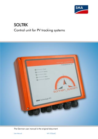
  • 1. The German user manual is the original document User Manual NF11ST3xxAC SOLTRK Control unit for PV tracking systems
  • 2. Produced by SMA Solar Technology AG NF11ST3xxAC User manual Contents 1 Notes on this Document .................................................................................. 5 1.1 Target Group ........................................................................................................ 5 1.2 Validity ................................................................................................................. 5 1.3 Symbols Used ...................................................................................................... 6 2 SOLTRK ......................................................................................................... 7 2.1 Application and Function ....................................................................................... 7 2.2 Functions ............................................................................................................. 8 2.3 Scope of Delivery .................................................................................................. 9 2.4 Identification ......................................................................................................... 9 2.4.1 Name Plate ................................................................................................................9 2.4.2 Firmware Version .......................................................................................................9 3 Safety Instructions ......................................................................................... 10 4 Installation .................................................................................................... 11 5 Connection ................................................................................................... 12 5.1 Wiring Diagram and Cable Feed-Throughs .......................................................... 12 5.2 Connecting the Limit Switches and Drives ........................................................... 13 5.3 Connecting the Communication Device to the Inverter .......................................... 14 5.3.1 Wiring Diagram (Inverter to SOLTRK) ..................................................................... 14 5.4 Connecting the communication to the Sunny WebBox .......................................... 17 5.4.1 Cabling Notes ......................................................................................................... 17 5.4.2 Jumper Functions ................................................................................................... 17 5.4.3 Wiring Diagram Sunny WebBox to SOLTRK ........................................................... 18 5.4.4 Wiring Diagram Sunny WebBox with RS485 Power Injector .................................... 21 5.5 Connecting another SOLTRK .............................................................................. 23 5.6 Connecting the Power Supply and Overdrive Line ................................................ 27 5.7 Grounding Connection ........................................................................................ 28 6 Commissioning ............................................................................................. 29 6.1 Switching on the Power Supply ........................................................................... 29
  • 3. Produced by SMA Solar Technology AG User manual NF11ST3xxAC 6.2 System Test in Manual Mode .............................................................................. 31 6.2.1 Checking the Installation ......................................................................................... 31 6.3 Configuring the Sunny WebBox and SOLTRK Parameters ................................... 34 6.3.1 Setting the Time, Date, Time Zone and Synchronisation .......................................... 34 6.3.2 Detecting the SOLTRK using the Sunny WebBox .................................................... 34 6.3.3 Assigning the detected SOLTRK devices ................................................................ 35 6.3.4 Determining and Setting the Geographic Location Data ........................................... 35 6.4 Calibrating the Travelling Range using the Manual Control Unit ............................ 38 6.4.1 Selecting the Calibration Mode ................................................................................ 38 6.4.2 Performing South Calibration .................................................................................. 39 6.4.3 Performing Sun Calibration ..................................................................................... 40 6.4.4 Performing Quick Calibration ................................................................................... 41 6.5 Starting Automatic Operation and Overdrive Function Test ................................... 42 7 Tracking Function .......................................................................................... 43 7.1 Movement of the Module Surface in “Auto” Operating Mode ............................... 44 7.1.1 Motor Test .............................................................................................................. 44 7.1.2 Reference Run ........................................................................................................ 44 7.1.3 Standby .................................................................................................................. 45 7.1.4 Tracking .................................................................................................................. 45 7.2 Operation using Remote Operating Commands ................................................... 46 7.3 track_back:Special Function to Prevent Shadowing Effects .................................. 47 8 Maintenance and Cleaning ............................................................................ 48 8.1 Maintenance ....................................................................................................... 48 8.2 Cleaning ............................................................................................................. 48 9 Decommissioning .......................................................................................... 49 9.1 Disassembly ....................................................................................................... 49 9.2 Packaging for Shipment ...................................................................................... 49 9.3 Disposal ............................................................................................................. 49 10 Technical Data .............................................................................................. 50 11 Appendix ....................................................................................................... 51
  • 4. Produced by SMA Solar Technology AG NF11ST3xxAC User manual 11.1 LEDs ............................................................................................................. 51 11.2 Channel List ................................................................................................... 53 11.2.1 Spot Values ............................................................................................................ 53 11.2.2 Parameters ............................................................................................................. 57 11.3 Remote Control Mode (Remote Operation) ...................................................... 58 11.4 Errors ............................................................................................................. 60 11.4.1 Clearing Permanent Errors (LED) ............................................................................ 66 11.5 Using the Manual Control Unit ........................................................................ 67 11.5.1 Summary of Manual Control Unit Commands .......................................................... 68 11.6 Cabling Recommendations ............................................................................. 69 11.6.1 Communication ....................................................................................................... 69 11.6.2 Power supply .......................................................................................................... 70 12 Accessories ...................................................................................................... 71 13 Contact ............................................................................................................ 72
  • 5. Produced by SMA Solar Technology AG User manual NF11ST3xxAC 5 1 Notes on this Document 1.1 Target Group This document is a user manual aimed at installers and operators. It contains a de- scription on the installation, commissioning and operation of the SOLTRK. The appendix includes summary tables on • the LED functions • the channel lists • error codes and descriptions • a description of commands for remote operation • the manual control functions The activities described in this document are only to be performed by qualified electri- cians. They are marked with a danger notice. 1.2 Validity This user manual applies to SOLTRK firmware version 1.6 and Sunny WebBox software version 1.42 and above. This user manual only describes the functional units of the SOLTRK control unit. It is not a user manual for the sonnen_system nor does it replace the user manual for the sonnen_system.
  • 6. Produced by SMA Solar Technology AG 6 NF11ST3xxAC User manual 1.3 Symbols Used The following hazard categories are used in this document. DANGER! The term Danger indicates a hazard which, if ignored, can lead to fatal injury WARNING! The term Warning indicates a hazard which, if ignored, can lead to seri- ous injury or death. CAUTION! The term Caution indicates a hazard which, if ignored, can lead to injury. ATTENTION! The term Attention indicates a hazard which, if ignored, can lead to mate- rial damage Other symbols This symbol indicates a notice which, if ignored, will make the procedure or operation more difficult.
  • 7. Produced by SMA Solar Technology AG User manual NF11ST3xxAC 7 2 SOLTRK 2.1 Application and Function SOLTRK is a control unit for PV tracking systems which determines the sun’s position using astronomic calculations and automatically aligns the surface of the photovoltaic modules towards the sun. Tracking is performed in two axes, namely horizontal (X-axis = azimuth) and vertical (Y-axis = elevation). The following parameters must be entered into the SOLTRK using an SMA “Sunny WebBox” data logger connected to the RS485 interface: • longitude and latitude of the location • current date and time Up to 50 units (SOLTRK and inverters) can be managed by one Sunny WebBox. The travelling range of the tracking system can be restricted to prevent or reduce reciprocal shadowing of the sonnen_system installations (track-back). The SOLTRK can be employed in locations at latitudes between 25 ° and 65 ° north. The longitude of the location can lie between –180 ° and +180 °.
  • 8. Produced by SMA Solar Technology AG 8 NF11ST3xxAC User manual 2.2 Functions SOLTRK functions • Automatic tracking of the sonnen_system in the horizontal and vertical axes by calculating the position of the sun based on the longitude/latitude of the location, the date and the time. • Controlling the elevation and azimuth drives and analysing the pulse signals from the rotary sensors. • Error monitoring during setup and tracking operation. • Optional connection of an “overdrive voltage” (overdrive), which enables the sonnen_system to move into a safe horizontal position, for example during a storm, independently of the SOLTRK control processor. • Reduced reciprocal shadowing of the sonnen_systems by using the Sunny Web- Box user interface to restrict the travelling range. Operation • Via the Sunny WebBox user interface or via manual control (only during commis- sioning and maintenance). Indication of the operating modes • The operating mode is indicated by the LEDs on the front of the SOLTRK. Remote maintenance / remote operation • The Sunny WebBox user interface can be used to configure, read and, if neces- sary, control or reset the SOLTRK. This allows efficient remote maintenance from any Internet connection, providing the Sunny WebBox is connected to the Internet. If an Internet connection is not available, direct Ethernet access to the Sunny WebBox is required in order to administrate the system. Deployment location • The SOLTRK can be deployed in locations situated between 25 ° and 65 ° lati- tude north and –180 ° to +180 ° longitude. Power supply • 24 V DC connection. (Maximum power consumption 5 A per sonnen_system). RS485 communication • To Sunny WebBox (software version 1.42 or higher) and inverter
  • 9. Produced by SMA Solar Technology AG User manual NF11ST3xxAC 9 2.3 Scope of Delivery SOLTRK 2.4 Identification 2.4.1 Name Plate You can identify the SOLTRK from its name plate (see figure to the right). The name plate is located on the right side of the SOLTRK housing. 2.4.2 Firmware Version The firmware version can be displayed on the Sunny WebBox once it has successfully detected the SOLTRK. The firmware version is displayed as a channel (see section 11.2 „Channel List“ on page 53). Hardware version of the SOLTRK
  • 10. Produced by SMA Solar Technology AG 10 NF11ST3xxAC User manual 3 Safety Instructions SOLTRK is a single-channel system. This means that the SOLTRK could provoke invol- untary movements if a hardware or software error occurs. Therefore, pay particular attention to the following safety instructions. CAUTION! Risk of injury or material damage. Unintended movements of the sonnen_system could result in injury or ma- terial damage. • Remove all voltages from the SOLTRK before working on the son- nen_system. • No persons or objects should be within the turning and tilting range of the sonnen_system. Ensure that this includes the entire range of travel, even beyond the position of the limit switch. • During commissioning and maintenance, the SOLTRK may only be operated in manual mode and without the external overdrive fuse. • Users are responsible for their own actions during manual operation. • The user must verify that the control unit and system are working properly before changing to automatic operation.
  • 11. Produced by SMA Solar Technology AG User manual NF11ST3xxAC 11 4 Installation This section describes the installation of the SOLTRK on the mounting plate of the son- nen_system. 1. Unscrew the cover on the SOLTRK. 2. Use the screws provided to attach the SOLTRK to the sonnen_system mount- ing plate, as shown in the figure to the right. Please note that even if the cover has been correctly fitted, the SOLTRK housing only meets the specified protection degree (IP65) after all the ca- bles have been installed. Complete the installation procedure to ensure that no humidity can enter the unit.
  • 12. Produced by SMA Solar Technology AG 12 NF11ST3xxAC User manual 5 Connection 5.1 Wiring Diagram and Cable Feed-Throughs Wiring diagram Front view of SOLTRK showing cable feed-throughs
  • 13. Produced by SMA Solar Technology AG User manual NF11ST3xxAC 13 5.2 Connecting the Limit Switches and Drives 1. Unscrew the appropriate cable screw connection to make the connection to the SOLTRK (see figure to the right). 2. Thread the cable through the respective cable feed-through. 3. Connect the numbered wires of the motor cables to the corresponding con- nections inside the SOLTRK (see figure below). The cables are connected 1:1. The polarity of the limit switch connections is arbitrary. The motor will be damaged if the polarity of the motor connections is in- correct. Carefully check the connections. 4. Manually tighten the cable screw connections (1.8 Nm).
  • 14. Produced by SMA Solar Technology AG 14 NF11ST3xxAC User manual Inside view of SOLTRK, control and drive connections • Azimuth drive = horizontal adjustment (X-axis) • Elevation drive = vertical adjustment (Y-axis) 5.3 Connecting the Communication Device to the Inverter Use the cables recommended in section 11.6 ”Cabling Recommendations” on page 69. 5.3.1Wiring Diagram (Inverter to SOLTRK) WARNING! Danger of electrocution! High voltages are present inside the inverter which can lead to serious injury or even death if touched. • All work on the inverters may only be performed by qualified electri- cians! • Before making the connections, isolate the inverter as described in the inverter documentation. • Follow all the safety instructions given in the inverter documentation.
  • 15. Produced by SMA Solar Technology AG User manual NF11ST3xxAC 15 Connection in the Inverter 1. Open the inverter as described in the inverter documentation. 2. Remove all jumpers and termination resistors (depending on the type of in- verter) for termination or signal bias which may be in the inverter. Refer to the instructions in the documentation on the RS485 communication interface on how to perform this procedure. 3. Connect the cable to the communication interface in the inverter as de- scribed in the documentation on the RS485 communication interface. Also refer to the poster “wiring principles RS485_sonnen_system”. 4. Lay the cable securely, using suitable fastening materials. Connection in the SOLTRK 5. Unscrew the SOLTRK cable screw connection which is shaded in the figure below. 6. Pull the cable through the cable screw connection. 7. Strip the cable shield inside the SOLTRK and connect the shield to the SOLTRK terminal (see figure below).
  • 16. Produced by SMA Solar Technology AG 16 NF11ST3xxAC User manual 8. Connect the wires inside the SOLTRK to the “Sunny Boy” connection (see fig- ure below). 9. Shorten unnecessary conductors back to the cable sheath to prevent short circuits occurring. 10. Manually tighten the cable screw connection (1.8 Nm). 11. Lay the cable securely, using suitable fastening materials.
  • 17. Produced by SMA Solar Technology AG User manual NF11ST3xxAC 17 5.4 Connecting the communication to the Sunny WebBox 5.4.1 Cabling Notes The cable length and quality can adversely affect the signal quality. To achieve good results, observe the instructions in section 11.6 “Cabling Recommendations” on page 69. 5.4.2 Jumper Functions Termination To ensure the signal quality of the RS485 communication bus, this must be terminated in the two devices at the end of the RS485 communication bus. Refer to the documentation for the end device on how to configure the termination resistor. Termination is limited to the two devices at the end of the RS485 communication bus. This is illustrated in the following figure: The following devices can be found at each of the two ends of the RS485 data bus and must be terminated accordingly: • SOLTRK + SOLTRK • SOLTRK + Sunny WebBox • SOLTRK + Sunny SensorBox • Sunny WebBox + Sunny SensorBox Also refer to the poster “wiring principles RS485_sonnen_system”.
  • 18. Produced by SMA Solar Technology AG 18 NF11ST3xxAC User manual Signal biasing To ensure the signal quality of the RS485 communication bus, a maximum of one bias must be connected in the RS485 communication bus. We recommend doing this with the Sunny WebBox. Please refer to the Sunny WebBox documentation. 5.4.3Wiring Diagram Sunny WebBox to SOLTRK If an RS485 power injector is connected to your Sunny WebBox, refer to the details in section 5.4.4 “Wiring Diagram Sunny WebBox with RS485 Power Injector” on page 21. Connections in the Sunny WebBox 1. Use the plug provided with the Sunny WebBox for the SMA-COM connection. 2. Connect the cable to the Sunny Web- Box, as shown in the figure to the right. Refer to the table for details on the twisted pair cables.
  • 19. Produced by SMA Solar Technology AG User manual NF11ST3xxAC 19 3. Take note of the conductors' colour coding: WebBox “SMA COM” Conductor colour SOLTRK “RS485 IN” *2 *D+ 5 GND *7 *D- * The conductors 2 and 7 (D+ and D-) must be a twisted pair. 4. If the Sunny WebBox is one of the two end points of the RS485 data bus, check that jumper J1A is mounted. 5. Check that jumpers J1B and J1C are fitted to ensure signal biasing.
  • 20. Produced by SMA Solar Technology AG 20 NF11ST3xxAC User manual Connection in the SOLTRK 6. Unscrew the SOLTRK cable screw connec- tion which is shaded in the figure to the right. 7. Pull the cable through the cable screw connection. 8. Strip the cable shield inside the SOLTRK and connect the shield to the SOLTRK ter- minal (see figure below). 9. Connect the cable to the SOLTRK as shown in the figure above. Use the conductor colours you noted earlier. 10.Manually tighten the cable screw connection (1.8 Nm).
  • 21. Produced by SMA Solar Technology AG User manual NF11ST3xxAC 21 5.4.4Wiring Diagram Sunny WebBox with RS485 Power Injector If a Sunny SensorBox is used in conjunction with your Sunny WebBox and the RS485 power injector is directly connected to the Sunny WebBox, connect the cabling as fol- lows. Sunny WebBox to RS485 Power Injector 1. Pull out the RS485 Power Injector's power plug. 2. Use the plug provided with the Sunny WebBox for the SMA-COM connection. 3. Connect the RS485 Power Injector to the Sunny WebBox as shown in the figure to the right. Refer to the table for details on the twisted pair cables. 4. Take note of the conductors' colour coding. WebBox SMA-COM Conductor colour RS485 Power Injector RS485 IN *2 *D+ 5 GND *7 *D- * The conductors 2 and 7 (D+ and D-) must be a twisted pair. 5. If the Sunny WebBox is one of the two end points of the RS485 data bus, check that jumper J1A is mounted. 6. Check that jumpers J1B and J1C are fitted to ensure signal biasing.
  • 22. Produced by SMA Solar Technology AG 22 NF11ST3xxAC User manual RS485 Power Injector to SOLTRK 7. Unscrew the SOLTRK cable screw connection which is shaded in the fig- ure to the right. 8. Pull the cable through the cable screw connection. 9. Strip the cable shield inside the SOLTRK and connect the shield to the SOLTRK terminal (see figure below). 10. Connect the RS485 power injector to the SOLTRK as shown in the figure above. Refer to the table for details on the twisted pair cables.
  • 23. Produced by SMA Solar Technology AG User manual NF11ST3xxAC 23 11. Take note of the conductors' colour coding. RS485 Power Injector RS485 + Power OUT Conductor colour SOLTRK RS485 IN *+12 V *+12 V *GND *GND *D+ *D+ *D- *D- *The +12 V and GND conductors, as well as the D+ und D- conductors must both be twisted pairs. 12. Manually tighten the cable screw connection (1.8 Nm). 5.5 Connecting another SOLTRK 1. Remove the termination resistor on the “RS485 OUT” connection of the SOLTRK. 2. Unscrew the SOLTRK cable screw con- nection which is shaded in the figure to the right (next to figure RS485 OUT). 3. Pull the cable through the cable screw connection.
  • 24. Produced by SMA Solar Technology AG 24 NF11ST3xxAC User manual 4. Strip the cable shield inside the SOLTRK and connect the shield to the SOLTRK terminal (see figure below). 5. Connect the wires to the “RS485 OUT” connection of the SOLTRK as shown in the figure to the right. Refer to the ta- ble for details on the twisted pair ca- bles.
  • 25. Produced by SMA Solar Technology AG User manual NF11ST3xxAC 25 6. Take note of the conductors' colour coding: SOLTRK “RS485 OUT” Conductor colour SOLTRK “RS485 IN” *+12 V *+12 V *GND *GND *D+ *D+ *D- *D- * The +12 V and GND conductors, as well as the D+ und D- conductors must both be twisted pairs. 7. Manually tighten the cable screw connection (1.8 Nm).
  • 26. Produced by SMA Solar Technology AG 26 NF11ST3xxAC User manual Additional SOLTRK 8. Unscrew the cable screw connection which is shaded in the figure to the right (figure next to RS485 IN) on the next SOLTRK. 9. Pull the cable through the cable screw connection. 10. Strip the cable shield inside the SOLTRK and connect the shield to the SOLTRK terminal (see figure be- low). 11. Connect the wires to the “RS485 IN” connection on the other SOLTRK as shown in the figure above. Use the conductor colours you noted earlier. 12. Manually tighten the cable screw connection (1.8 Nm). 13. Several SOLTRK can be connected together in the same manner. The termination resistor remains plugged into the RS485 data bus of the last SOLTRK (“RS485 OUT” connection). 14. Lay the cables securely, using suitable fastening materials.
  • 27. Produced by SMA Solar Technology AG User manual NF11ST3xxAC 27 5.6 Connecting the Power Supply and Overdrive Line Connect the power supply (24 V DC) and overdrive as follows: 1. Unscrew the appropriate cable screw connection to make the connection (see figure to the right, view of SOLTRK cable screw connections). 2. Pull the cable through the cable screw connec- tion. 3. Connect the power supply and overdrive line inside the SOLTRK as shown in the figure below. SOLTRK further SOLTRK
  • 28. Produced by SMA Solar Technology AG 28 NF11ST3xxAC User manual 4. Take note of the conductors' colour coding: Connection Conductor colour Power supply +24 V GND Overdrive + - 5. Manually tighten the cable screw connections (3.5 Nm). 5.7 Grounding Connection 1. Fit a suitable ring cable lug to the earthing connection (see figure to the right) on the SOLTRK. 2. Ground the SOLTRK to a suitable earthing star point.
  • 29. Produced by SMA Solar Technology AG User manual NF11ST3xxAC 29 6 Commissioning Commissioning of the SOLTRK occurs in five steps: • Switching on the power supply • System test in manual mode • Configuring the SOLTRK parameters • Calibrating the travelling range • Activating the automatic tracking function 6.1 Switching on the Power Supply 1. Unscrew the cover on the SOLTRK. 2. Remove the overdrive fuse (see figure to the right) to prevent any accidental movement of the sonnen_system. 3. Set the toggle switch in the SOLTRK to “MANUAL” (see figure to right). The SOLTRK switches to manual operation. 4. Switch on the power supply. 5. Check the LEDs on the SOLTRK: − The Power LED must glow green. − The Error LED must be off. − The Overdrive LED must flash (man- ual operation).
  • 30. Produced by SMA Solar Technology AG 30 NF11ST3xxAC User manual Connecting the manual control unit 6. Attach the plug from the manual control unit into the corresponding connec- tor on the SOLTRK (see figure below) and screw tight. Refer to these two fig- ures to determine which manual control unit matches the one you have. A description of the keypad functions is given in section 11.5.1 “Summary of Manual Control Unit Commands” on page 68.
  • 31. Produced by SMA Solar Technology AG User manual NF11ST3xxAC 31 6.2 System Test in Manual Mode Users are responsible for their own actions during manual operation. 6.2.1 Checking the Installation The procedure for checking the installation using the manual control unit is described below. Check direction of travel for X and east-west limit switches The figures to the right below show the position of the limit switches on the two son- nen_systems 3_30 and 3_40/3_60. 1. Press the EAST key  and keep it held down. The X-motor should move the sonnen_system in an easterly direction. 2. Operate the east-limit switch (see figure to the right, position 1). The motor should stop. 3. Release the East key  before releasing the east-limit switch. 4. Press the WEST key  and keep it held down. The X-motor should move the sonnen_system in a westerly direction. 5. Operate the west-limit switch (see figure to the right, position 2). The X-motor should stop. 6. Release the WEST key  before releasing the west-limit switch.
  • 32. Produced by SMA Solar Technology AG 32 NF11ST3xxAC User manual Check direction of travel for Y and elevation-limit switches The figures to the right below show the position of the limit switches on the two son- nen_systems 3_30 and 3_40/3_60. 1. Press the DOWN (70°) key  and keep it held down. The Y-motor should move the son- nen_system towards the 70° position. 2. Operate the 70°-limit switch (see figure to the right, position 1). The Y-motor should stop. 3. Release the DOWN (70°)  key before re- leasing the 70°-limit switch. 4. Press the UP (0°) key  and keep it held down. The Y-motor should move the sonnen_system toward the 0° position. 5. Operate the 0°-limit switch (see figure to the right, position 2). The Y-motor should stop. 6. Release the UP (0°) key  before releasing the 0°-limit switch.
  • 33. Produced by SMA Solar Technology AG User manual NF11ST3xxAC 33 Adjusting the 0°-limit switch 1. Loosen the bolt on the length-adjustable twist lever and push it in completely. ATTENTION! A minimum of 30 mm of the piston rod of the elevation drive must remain visible at all times while performing the following steps. See the figure be- low. If the piston rod is not minimum 30 mm visible, the elevation drive will be damaged. 2. Press the UP (0°) key  and keep it held down until the central beam of the sonnen_system is right angled to its main beam. 3. Push the twist lever under the central beam until the 0°-limit switch audibly switches over. 4. Tighten the bolt on the length-adjustable twist lever to 0.8 to 1 Nm.
  • 34. Produced by SMA Solar Technology AG 34 NF11ST3xxAC User manual 5. Press the DOWN (70°) key  and keep it held down until the twist lever no longer touches the central beam. 6. Press the UP (0°) key  and keep it held down. 7. The Y-motor should stop when the 0°-limit switch switches over. Check the angularity of the central beam to the main beam again. 6.3 Configuring the Sunny WebBox and SOLTRK Parameters 6.3.1 Setting the Time, Date, Time Zone and Synchronisation 1. Commission the Sunny WebBox as described in the Sunny WebBox user manual. 2. Log on via the Sunny WebBox user interface. 3. Set the time zone of your location as described in the Sunny WebBox user manual. 4. If the Sunny WebBox can access the internet, set “Automatic Time Synchroni- sation” function to “Yes”. It is imperative that the time and date on the Sunny WebBox is correctly set. To ensure the time and date are accurate, select “Automatic Time Syn- chronisation” (only possible if the Sunny WebBox can access the internet). 5. Set automatic summer/winter changeover to “Yes”. 6. Set the time and the date. It is not necessary to manually set the time if you are using the "Automatic Time Synchronisation" function. 7. Save the settings. 6.3.2 Detecting the SOLTRK using the Sunny WebBox 1. Configure the following on the Sunny WebBox user interface: − Set the interface to "SMA-COM". − Set the transfer protocol to "SMA-NET". − Set the baud rate to “1200”.
  • 35. Produced by SMA Solar Technology AG User manual NF11ST3xxAC 35 2. Start detection as described in the Sunny WebBox user manual. 6.3.3 Assigning the detected SOLTRK devices The device type and serial number of the detected SOLTRK devices are displayed on the Sunny WebBox user interface. The displayed serial numbers can be compared with those printed on the name plates of the SOLTRK devices and assigned accordingly. It is also recommended that you make a note of the assignment between the SOLTRK and the Sunny Boy so that the data can later be displayed accordingly, e.g. on the Sunny Portal. 6.3.4 Determining and Setting the Geographic Location Data The longitude and latitude coordinates of your location must be entered into the SOLTRK to enable it to make the tracking calculations. The degrees longitude and latitude (WGS84) for your location may be determined us- ing the “Google Earth” program at http://earth.google.de or by means of a GPS re- ceiver. 1. Log onto the Sunny WebBox user interface as an installer by entering the ap- propriate password. 2. Open the SOLTRK parameter list. 3. Enter the longitude coordinate for your location using the “LocCoordLong” parameter. The value in degrees can lie in the range –180 ° (to the west of Greenwich) to +180 ° (to the east of Greenwich) with two decimal places. 4. Enter the latitude coordinate for your location using the “LocCoordLat” pa- rameter. The value in degrees can lie in the range 25 ° to 65 ° with two decimal places.
  • 36. Produced by SMA Solar Technology AG 36 NF11ST3xxAC User manual The values are entered in degrees. The two decimal places therefore cor- respond to 1/100 degree (and not minutes). If the data is only available in degrees/minutes/seconds notation, the decimal places can be calculated as follows: • (minutes/60) + (seconds/ 3600) Example: Location Niestetal 51 °19´52 corresponds to 51 + (19/60) + (52/3600), which equates to 51.3172 degrees (enter the next rounded value, i.e. 51.32). Take care to ensure that the data relates to the WGS84 coordinate system. Standard settings for further parameters 5. Enter the values given in the column ‘setting’ in the table of parameters be- low. Channel Setting 3 ElevationLimit 65° 5 LocCoordLat Enter location coordinates: Latitude 6 LocCoordLong Enter location coordinates: Longitude 9 RefErrMax Set to 2 10 ReftimeMax Set to 7 11 Remote Control command and error acknowledgement (see section 7.2 “Operation using Remote Operating Commands” on page 46. 14 SensBackY Set to 2500
  • 37. Produced by SMA Solar Technology AG User manual NF11ST3xxAC 37 Channel Setting 17. TrkDiffMin 3° when using the IMO slewing drive, otherwise 0.50° 18. TypeSelect Value depends on the used slewing drive and son- nen_system: 1: sonnen_system 3_40/3_60; IMO WD-L 0419 2: sonnen_system 3_30; KMI SE1 4C-85M 3: sonnen_system 3_40/3_60; KMI SE17B-102M 6. Save for all devices of the device type. Further parameters are described in section 11.2.2 ”Parameters” on page 57.
  • 38. Produced by SMA Solar Technology AG 38 NF11ST3xxAC User manual 6.4 Calibrating the Travelling Range using the Manual Control Unit The control unit requires exact reference data to ensure precise tracking. Since the sonnen_system can never be perfectly aligned mechanically during installation, the control unit requires a reference value for the azimuth position. The reference value is determined once for each sonnen_system. This is value is permanently stored in the control unit. 6.4.1 Selecting the Calibration Mode Calibration is a sub-function of manual operation. Three calibration modes are avail- able: “sun calibration”, “south calibration” and “quick calibration”. In the case of sun calibration, the module surface is aligned as precisely as possi- ble towards the sun; in the case of south calibration it is aligned towards the south. Tracking quality is therefore dependent on the accuracy of alignment to the south or the sun. Quick calibration uses a faster calibration process and can only be used if the position of the X-motor is already known. South calibration South calibration requires a very accurate compass and the current declination (devia- tion between magnetic north and true north) for your location. The declination angle can be determined from topographical maps for your location or calculated on the Internet. http://www.ngdc.noaa.gov/seg/geomag/jsp/struts/calcDeclination We recommend the following compass: RECTA DP 65 When determining the direction, take care to ensure that the compass is not placed in the magnetic interference field produced by the steel struc- ture, DC cables or the inverter.
  • 39. Produced by SMA Solar Technology AG User manual NF11ST3xxAC 39 Sun calibration Sun calibration can only be used when the following prerequisites are fulfilled: • The sun is shining, • The SOLTRK has been detected using the Sunny WebBox • The time zone, time and longitude/latitude coordinates for your location have been entered in the Sunny WebBox user interface. Quick calibration Quick calibration can only be used if either a south or a sun calibration has been per- formed. This means the position of the X-motor is already known from earlier refer- encing. This saves significant time during calibration, particularly when readjusting the systems. 6.4.2 Performing South Calibration Stop calibration = Press arrow key If a problem occurs, the calibration process can always be stopped by pressing any KEY on the manual control unit. The calibration process must then be repeated. 1. Check and (if necessary) correct the following: − Has the fuse for the overdrive circuit been removed? − Toggle switch set to “MAN”? − Manual control unit plugged in? 2. Align the module surface in the X-direction as close as possible to south by pressing the arrow keys on the manual control unit. 3. Next press the keys “ENTER, UP (0°)  and EAST ” at the same time. The calibration run of the sonnen_system starts after 3 seconds. Wait for the calibration run to complete. − SOLTRK drives to the east- limit switch, determines its position and stores this value internally.
  • 40. Produced by SMA Solar Technology AG 40 NF11ST3xxAC User manual − During the calibration run, the motor LED glows once the X-position is known or flashes if the X-position value is invalid. 4. Check whether the calibration run has been successful. − − Calibration unsuccessful: The Error LED flashes if referencing at the limit switch was not performed correctly. The Error LED glows if the determined limit switch position does not lie between –135 ° and –160 °. One possible cause of the error is that the sonnen_system was not prop- erly orientated to the south or that the east-limit switch is not in the correct position. If necessary, adjust the east-limit switch. Calibration successful: Motor LED and Error LED are off. − Repeat the calibration process. 6.4.3 Performing Sun Calibration Stop calibration = Press arrow key If a problem occurs, the calibration process can always be stopped by pressing any KEY on the manual control unit. The calibration process must then be repeated. 1. Check and (if necessary) correct the following: − Has the fuse for the overdrive circuit been removed? − Toggle switch set to “MAN”? − Manual control unit plugged in? 2. Orientate the module surface in the X-direction as closely as possible to- wards the sun by pressing the arrow keys on the manual control unit. If there is a gap in the centre of the module surface, align the module array so that the light cast through the gap shines onto the centre of the mast or the rotat- ing head.
  • 41. Produced by SMA Solar Technology AG User manual NF11ST3xxAC 41 3. Next press the keys ENTER, DOWN  and WEST  at the same time. The calibration run of the sonnen_system starts after 3 seconds. Wait for the calibration run to complete. − SOLTRK drives to the east-limit switch, determines its position and stores this value internally. − During the calibration run, the motor LED glows once the X-position is known or flashes if the X-position value is invalid. 4. Check whether the calibration run has been successful. − − Calibration unsuccessful: The Error LED flashes if referencing at the limit switch was not performed correctly. The Error LED glows if the determined limit switch position does not lie between –135 ° and –160 °. One possible cause of the error is that the sonnen_system was not prop- erly orientated towards the sun. Calibration successful: Motor LED and Error LED are off. − Repeat the calibration process. 6.4.4 Performing Quick Calibration Quick calibration can only be performed if a south or a sun calibration has been suc- cessful. This means that calibration is started from a known position (from an earlier reference). This saves significant time during sonnen_system calibration and readjust- ment. 1. At the same time, press the keys ENTER, DOWN (70°)  and WEST . The calibration run of the sonnen_system starts after 3 seconds. Calibration can be terminated as soon as the LED glows permanently. If the position of the X-motor is known when starting the calibration procedure, SOLTRK uses it to calculate and store internally the new position of the limit switch. If this results in a value outside the valid range from –160 ° to –135 °, the limit switch position is set to –145 ° and the X-position to unknown (the MOTOR LED will flash during the subsequent run). Premature termination of a calibration run when the Motor LED is flashing will result in the SOLTRK setting the limit switch position to –145 ° and the X-position to unknown.
  • 42. Produced by SMA Solar Technology AG 42 NF11ST3xxAC User manual 6.5 Starting Automatic Operation and Overdrive Function Test To activate automatic operation, proceed as follows: 1. Press the DOWN (70°)  key and keep it held down until the module surface is in an inclined position. 2. Detach the manual control unit. 3. Insert the fuse in the SOLTRK (see fig- ure to right). CAUTION! Risk of injury or material damage! The sonnen_system travel in overdrive mode can cause injuries and mate- rial damage. When one or more sonnen_systems are installed, only start the overdrive test as described under steps 4 and 5 after all SOLTRK units have been set up and nobody is working on the sonnen_systems any longer. 4. Operate the overdrive switch S2 (3S1) in the DC power supply safeguard. (See figure to the right). The module surface must travel to 0° position. 5. Operate the overdrive switch in the DC power supply safeguard again. 6. Set the toggle switch in the SOLTRK to “AUTO”. The SOLTRK switches to auto- matic operation. The Sunny WebBox user interface then displays at spot value “(Mode)” the value “Auto” for automatic operation. 7. Screw the cover back onto the SOLTRK. Ensure that the cover fits correctly to ensure a tight seal.
  • 43. Produced by SMA Solar Technology AG User manual NF11ST3xxAC 43 7 Tracking Function This section describes the travel characteristics of the sonnen_system. The following general definitions apply: • The horizontal value is the rotation of the module surface from the southerly po- sition. South is designated as 0 °. Adjustments to the east and west are negative and positive respectively. East is therefore –90 ° and west +90 °. • The vertical value is the tilt angle between the module surface and the horizontal position. The 0°-position (level surface) is therefore 0 degrees; the vertical posi- tion of the module surface corresponds to 90 degrees. The mechanism allows a Y-adjustment between 0 ° and 70 °.
  • 44. Produced by SMA Solar Technology AG 44 NF11ST3xxAC User manual 7.1 Movement of the Module Surface in “Auto” Operating Mode The movements of the module surface are described below: • Motor test • Reference run • Standby • Tracking (module surface follows the sun) − Standby (02.00 until sunrise) − Tracking (sunrise to sunset) − Standby (sunset until 22.00) − Return (after 22.00, before 02.00) − Sleep (after return and until 02.00) 7.1.1Motor Test The motor test is executed when a test command is received. This command is gener- ated at the start of automatic operation as well as at sunrise. During the execution of the test, the Motor LED is glowing (during certain phases). If the Motor LED flashes (unknown position), a reference run is subsequently performed on the motor in question. An unsuccessful motor test will result in a permanent or temporary error (see section 11.4 “Errors” on page 60). The test command is only reset after the test has been suc- cessfully executed. 7.1.2 Reference Run A reference run is performed after the return at night. The reference run can be inter- rupted for a certain number of nights using the parameter RefTimeMax. An unsuccessful reference run will result in a temporary error and, in the case of nu- merous consecutive errors, a permanent error (see section 11.4 “Errors” on page 60). The reference run command is only reset after referencing has been successfully exe- cuted.
  • 45. Produced by SMA Solar Technology AG User manual NF11ST3xxAC 45 7.1.3 Standby The sonnen_system will remain in its initial position as long as the SOLTRK does not receive a valid time signal from the Sunny WebBox. If no time signal is received within approx. 15 minutes, it moves into the 0°-position. 7.1.4 Tracking Unless any of the above conditions are taken in up normal operation, the system switches to tracking mode. The system will switch to the following states during the course of the day. The stated times are local times (UTC + latitude degrees * 4 min- utes). − Standby (2 a.m. until sunrise) − The Standby state ends at sunrise. Sunrise is defined as half an hour prior to the calculated elevation angle of the sun being less than 91 °. At this point, the Y-target value suddenly changes from 5 ° to 70 ° and the X- target value from –130 ° to the azimuth angle at sunrise. Tracking (sunrise to sunset) A motor test is performed before tracking begins. X and Y then track the sun’s position as soon as the deviation between the set position and the target position exceeds 0.25 to 3 degrees (or parameter value). In this case, the X-position is limited between –135 ° and +135 ° and the Y-position between 0 ° and 70 ° (or the set parameter value). During tracking, the engine speed is reduced from 2,400 rpm to 1,200 rpm within the last 2 ° (X-motor) or 0.5 ° (Y-motor) of movement. If the travelling movement is interrupted (when actuating the limit switch) or prevented, the adjustment is completed immediately afterwards. A (temporary) error is signalled if the actual position deviates by more than 5 ° from the target value for longer than 15 minutes. Tracking ends at sunset. Sunset is defined as half an hour after the calculated eleva- tion angle of the sun being greater than 90 °. At this point, the Y-target value sud- denly changes from 70 ° to 5 ° (or the set parameter value) and the X-target value remains unchanged (azimuth angle for sunset position).
  • 46. Produced by SMA Solar Technology AG 46 NF11ST3xxAC User manual Standby (sunset until 10 pm) Sleep position (Y-position = 5 °) is maintained, the X-position remains unchanged (even after manual adjustment). The Standby state ends at 10 a.m. Return motion (after 10 p.m., before 2 a.m.) During a normal daily cycle, the return motion starts at exactly 10 p.m. However, if tracking is interrupted between 10 p.m. and 2 a.m. (overdrive, manual operation, er- ror, restart), the Sleep state is reached by first passing through the Return motion state. The Y-motor is driven to a position of 5 ° (this is already the case if previously in Standby). If an interruption has occurred (e.g. when actuating the limit switch), the movement is completed immediately afterwards. Depending on the value of the parameter RefTimeMax, Y-referencing is performed at the 0° limit switch. The X-motor is driven to a position of –130 degrees. If an interruption has occurred (e.g. when actuating the limit switch), the movement is completed immediately after- wards. Depending on the value of the parameter RefTimeMax, X-referencing is performed at the east-limit switch. Sleep (after return motion and until 2 a.m.) A Y-position of 5 ° and an X-position of -130 ° are maintained. Travelling move- ments only occur if adjustments are made (overdrive in case of wind, manual opera- tion). This also applies if the sun sets during this period. 7.2 Operation using Remote Operating Commands Remote operating commands are used to remotely control the SOLTRK from the Sunny WebBox. A description of the remote operating commands and their functions are given in the appendix, section 11.3 “Remote Control Mode (Remote Operation)“ on page 58.
  • 47. Produced by SMA Solar Technology AG User manual NF11ST3xxAC 47 7.3 track_back: Special Function to Prevent Shadowing Effects In order to prevent reciprocal shadowing of the sonnen_systems (for example if the sun is low in the East or West), the maximum inclination of the module surface can be lim- ited by means of parameters set on the Sunny WebBox interface. 1. Log onto the Sunny WebBox user interface as an installer by entering the ap- propriate password (SMA). 2. Open the SOLTRK parameter list. 3. Enter the maximum inclination in degrees as the “ElevationLimit” parameter. The value in degrees can lie in the range 0 ° to 70 ° with two decimal places. This value is preset to 70 °, i.e. no restriction other than the maxi- mum possible mechanical inclination. 4. Save the settings.
  • 48. Produced by SMA Solar Technology AG 48 NF11ST3xxAC User manual 8 Maintenance and Cleaning 8.1 Maintenance If automatic time synchronisation with the Sunny Portal has not been activated on the Sunny WebBox user interface, check and (if necessary) correct the time on the Sunny WebBox user interface every 3 months. Check the fuse in the overdrive circuit every six months. This is simply done by activat- ing the overdrive function. A faulty fuse is indicated by the Error LED and the error number 1 (ERR_FUSE) is displayed on the Sunny WebBox user interface. Please refer to the error list in section 11.4 “Errors” on page 60. 8.2 Cleaning Do not clean the SOLTRK using a pressure washer otherwise water may enter the SOLTRK. Use a scratch-free cloth moistened only with water to avoid damaging the surface of the SOLTRK.
  • 49. Produced by SMA Solar Technology AG User manual NF11ST3xxAC 49 9 Decommissioning 9.1 Disassembly 1. Disconnect the SOLTRK from the supply voltage. 2. Unscrew the cover on the SOLTRK. 3. Remove the cables connected inside the SOLTRK. 4. Unscrew the SOLTRK from the sonnen_system mounting plate. 5. Screw the cover back on the SOLTRK. 9.2 Packaging for Shipment When returning the device to us, be sure to use packaging which adequately protects the device from damage during transport (if possible, the original packaging). 9.3 Disposal Dispose of the SOLTRK at an authorised disposal company.
  • 50. Produced by SMA Solar Technology AG 50 NF11ST3xxAC User manual 10 Technical Data Environmental conditions for operation Ambient temperature -20 °C to +55 °C Height 0 m to 2000 m above mean sea level (AMSL) EMC interference stability according to EN61000-6-2:2001 (inter- ference stability for industrial sector, also fulfils requirements for residential areas) EMC interference according to EN61000-6-3:2001 (inter- ference emissions in residential areas,also fulfils requirements for industrial areas) Protection rating IP65 (suitable for outdoor installation) Dimensions Size 280 mm x 240 mm x 70 mm (width x height x depth) Weight excl. packaging approx. 2000 g Power supply Operational voltage 24 Volt DC, ± 20%, 150 mA (motor off) max. 20 A (motor on) Power consumption < 3.6 W (motor has stopped) Interfaces Communication interface RS485 Inverter interface RS485 Motor interface X and Y motor control 0 V to 24 V and rotary sen- sor inputs Limit switches digital input, motor control Manual control digital TTL inputs Overdrive 24 V DC, max. 7,5 A (fused)
  • 51. Produced by SMA Solar Technology AG User manual NF11ST3xxAC 51 11 Appendix 11.1LEDs LED Status Function Power glows green Power supply is present. off No power supply. Activity flashes green No communication, no operation: Communication running (normal operation): No communication, autonomous operation: off/glowing Malfunction
  • 52. Produced by SMA Solar Technology AG 52 NF11ST3xxAC User manual LED Status Function Error flashes red A self-correcting device error has occurred. These errors are automatically cleared after 30 minutes. glows red A permanent device error has occurred. These errors are not cleared automatically. Maintenance action is required. See section 11.4 “Errors” on page 60. off No error present. Motor glows green At least one motor is being actuated. The positions of all actuated motors are known. flashes green At least one motor is being actuated. The position of at least one actuated motor is known. off No motor is being actuated. Overdrive glows green External overdrive is active. flashes green Manual operation is active: Remote operation is active: off Automatic operation is switched on, external over- drive is inactive.
  • 53. Produced by SMA Solar Technology AG User manual NF11ST3xxAC 53 11.2Channel List 11.2.1 Spot Values Channel Read Explanation 1 CurrAzimuth all Current azimuth angle of the sonnen_system. Unit: degrees 2 CurrElevation all Current tilt angle of the sonnen_system. Unit: degrees
  • 54. Produced by SMA Solar Technology AG 54 NF11ST3xxAC User manual Channel Read Explanation 3 Error all Current overall tracking status 1: ERR_FUSE (fuse damaged) 2: ERR_RELAIS (overdrive relay damaged) 3: ERR_X_DIR (error in azimuth direction) 4: ERR_Y_DIR (error in elevation direction) 5: ERR_TIMEOUT (25 min. timeout when command is being processed) 6: ERR_PULSCNT (Error of encoder system measuring) 7: ERR_X_RANGE (X pos<-170 or X pos>+170°) 8: ERR_SENS_POS (limit switch outside range -135 ..+160°, only possible in calibration mode!) 9: ERR_REFCNT (excessive amount of faulty reference runs) 10: ERR_RPCHALT (forced remote error command) 11: ERR_I_MAX (overcurrent) 12: ERR_I_STOP (motor stops without 0 current-> blocked state) 13: ERR_INV_XREF (error in azimuth reference) 14: ERR_INV_YREF (error in elevation reference) 15: ERR_X_MOV (motor test: minimum number of X-steps/ time unit not reached, azimuth) 16: ERR_Y_MOV (motor test: minimum number of Y-steps/ time unit not reached, elevation) 17: ERR_TEST (motor test: general power error, current proper- ties) 18: ERR_Y_RANGE (elevation range exceeded) 19: ERR_X_DELAY (tracking mode: longer than 15 Min. >5 deviation from target position, azimuth) 20: ERR_Y_DELAY (tracking mode: longer than 15 Min. >5 deviation from target position, elevation) 21: ERR_U24_LOW battery undervoltage (firmware version. 1.6 and higher) 4 Firmware all Firmware version
  • 55. Produced by SMA Solar Technology AG User manual NF11ST3xxAC 55 Channel Read Explanation 5 h-On all Total number of operating hours. Unit: h 6 HwVer all Hardware version 7 I-Azi- Act all Momentary current of the azimuth motor 8 I-Elev- Act all Momentary current of the elevation motor 9 lMaxAziMot all Maximum current of the azimuth motor (reset at night). Unit: mA 10 lMaxElevMot all Maximum current of the elevation motor (reset at night). Unit: mA 11 LastOverride all Local time at which last overdrive took place. 12 LastSync all Time of last valid time synchronisation by Sunny WebBox (UTC) 13 Mode all Summary of operating modes N/V: Invalid mode MANUAL: Manual mode AUTOMATIC: Automatic mode = Tracking ERROR: Permanent error DISTURBANCE: Disturbance WARNING: Warning
  • 56. Produced by SMA Solar Technology AG 56 NF11ST3xxAC User manual Channel Read Explanation 14 OperMode all Display the current operating mode of the SOLTRK. 0: ManualMode 1: OVERDRIVE (overdrive activated) 2: ERROR TEMP (temporary error – 30 min) 3: ERROR PERM (permanent error) 4: MOTOR TEST (motor test activated) 5: REFERENCING (reference run activated) 6: WAIT TIME (wait for change to time counter) 7: SAFE STATE (safe state after 15 min. without valid time change) 8: STANDBY (sun has set outside NIGHT MODE) 9: TRACKING (tracking mode) 10: RETURN EAST (return to east end switch) 11: NIGHT MODE (10 p.m. until 2 a.m.) 12: REMOTE OP (remote operation activated, via Webbox) 13: BOOT MODE (initial startup procedure) 15 OverrideCnt all Number of overdrives performed manually (driving to 0°-position). 16 ResetCnt all Indicates the total number of resets performed. 17 TargetAzi all Target value of azimuth angle Unit: degrees 18 TargetElev all Target value of tilt angle Unit: degrees 19 Voltage 24 all Current battery voltage
  • 57. Produced by SMA Solar Technology AG User manual NF11ST3xxAC 57 11.2.2 Parameters Channel Read Write Explanation 1 Device Number All Inst Nr. Of the Board for correlation between inverter and SOLTRK (firmware version 1.28 and higher) 2 Device Reset Inst Inst- Reset device (1) 3 ElevationLimit All Inst Maximal elevation angle to avoid reciprocal shadowing. Unit: Degree 4 Elevation Offset Inst Inst Offset in elevation direction (-35°…+35°) (firmware ver- sion 1.6 and higher) 5 LocCoordLat All Inst Location coordinate latitude. Unit: Degree with 2 decimal places 6 LocCoordLong All Inst Location coordinate longitude. Unit: Degree with 2 decimal places 7 Night Elevation All Inst Night position of module surface in elevation direction 8 Password Inst Inst Password for special function 9 RefErrMax Inst Inst Max. allowed reference errors until permanent error 10 RefTimeMax Inst Inst The number of nights in which no referencing is per- formed. If this parameter is changed or if the SOLTRK is restarted, referencing is always performed the following night. 11 Remote Inst Inst Adjusting command and error acknowledgment (see section 7.2“Operation using Remote Operating Com- mands“ on page 46 12 RemoteStep Inst Inst Number of degrees ‘driven’ at remote command UP /DOWN /EAST /WEST. RemoteStep = 0: unlimited driving (as far as limit stop or another remote command) (firmware version 1.6 and higher) 13 SensBackX Inst Inst Travelling distance at east-limit switch limit switch test 14 SensBackY Inst Inst Travelling distance at 0°-limit switch limit switch test
  • 58. Produced by SMA Solar Technology AG 58 NF11ST3xxAC User manual Channel Read Write Explanation 15 Serial Number All Inst SOLTRK serial number 16 StartDelay All Inst Delay in seconds at change-over from standby to track- ing at sunrise (StartDelay = 0: Value between 0-300 sec. depending on serial number) (firmware version 1.6 and higher) 17 TrkDiffMin Inst Inst Min. deviation to start tracking in 1/ 100 degree 18 TypeSelect All Inst 1-sosy 3_40/60 IMO; 2-sosy 3_30 KMI; 3-sosy 3_40/60 KMI 11.3Remote Control Mode (Remote Operation) In remote control mode (remote operation), the sonnen_system can be operated via a data interface. CAUTION! Risk of injury or material damage! Various safety functions are disabled in remote control mode. • Only activate remote control mode when the sonnen_system can be visually monitored. The remote control commands can be entered using the installer account on the Sunny WebBox user interface; the “Remote” parameter is used for this purpose (see section 11.2 “Channel List“ on page 53). Remote operation is activated as soon as a com- mand is entered. Remote operation then remains active for 30 minutes after which the system returns to automatic operation. To extend this time, enter any command within 30 minutes (e.g. NOP). QUIT exits remote operation.
  • 59. Produced by SMA Solar Technology AG User manual NF11ST3xxAC 59 Command code for parameter “Re- mote” CODE prior (until firm ware) Action 0: None 1: REFRESH_30s 9522501 30 minute timeout refresh for remote operation 2: STOP_ACT_CMD 9522502 Stop the current remote command 3: UP_EAST 9522503 Drive to 0°- position and East end position 4: UP 9522504 Drive to 0°- position (or parameter value RemoteStep) 5: DOWN 9522505 Drive to 70° position (or parameter value RemoteStep) 6: EAST 9522506 Drive to east limit stop (or parameter value Remot- eStep) 7: WEST 9522507 Drive to west limit stop (or parameter value Remot- eStep) 8: OVDRV_UP 9522508 Drive with max. velocity to the 0° position (emergency operation) 9: OVDRV_DOWN 9522509 Drive with max. velocity to 70° 10: WEST_90 9522510 Drive to 90° (alignment to West) 11: SOUTH 9522511 Drive to 0 (alignment to South) 12: EAST_90 9522512 Drive to 90 (alignment to East) 13: ELEV_35 9522513 Drive to 35° elevation 14: ERR_CLR 9522514 Delete all remote operating errors 15: FORCE_ERR 9522515 Set a permanent error 16: QUIT_REMOTE 9522516 Quit remote operation 17: MOT_TEST 9522517 Start the motor test 18: REF_SOUTH 9522518 Start the south referencing 19:REF_ASTRO 9522519 Start the Astronomical referencing 20: RPC_BUSY 9522520 Feedback command enable 21:RPC_MAX 9522521 n/a
  • 60. Produced by SMA Solar Technology AG 60 NF11ST3xxAC User manual 11.4Errors If an error occurs, the SOLTRK stops tracking mode and drives to the 0°-position (if possible). Errors are displayed in the parameter list on the Sunny WebBox and indi- cated by the Error LED on the SOLTRK housing. The Error LED can indicate two types of errors. • Error LED flashes red: − Self-correcting device error. These errors are automatically cleared after 30 minutes (number 11-21). • Error LED glows red: − A permanent device error has occurred (number 1-10, 21). These errors are not cleared automatically. Maintenance action is required. The Sunny WebBox indicates the tracking status and any errors by means of an error code for the “DriveError” parameter in the parameter list. A description of the error codes is given in section 11.2 ”Channel List” start- ing on page 53. The corrective actions for the indicated errors are given in the following table.
  • 61. Produced by SMA Solar Technology AG User manual NF11ST3xxAC 61 No. Errors Causes and eliminating errors 1. ERR_FUSE • The fuse is faulty. This error can only occur during overdrive operation. This error is only cleared when the fuse in overdrive operation is detected as “OK”. 1. Replace the fuse inside the SOLTRK. 2. Initiate overdrive to clear the error. 2. ERR_RELAIS • The change-over relay is defective. This error can only occur during the motor test. 1. Change the control unit. 3. ERR_INV_XDIR • The X-motor turns in the wrong direction. This error can only occur during the motor test. SOLTRK cannot determine if both the X-power terminals and X-sensor signals are reversed. The driving direction should therefore be checked using the manual control unit. 1. Reverse the signals for the X-rotary sensor. 2. Check the driving direction using the manual control unit. The sonnen_system should drive to the left when pressing the “LEFT” arrow key on the manual control unit. The sonnen_system should drive to the right when pressing the “RIGHT” ar- row key on the manual control unit.
  • 62. Produced by SMA Solar Technology AG 62 NF11ST3xxAC User manual No. Errors Causes and eliminating errors 4. ERR_INV_YDIR • The Y-motor turns in the wrong direction. This error can only occur during the motor test. SOLTRK cannot determine if both the Y-power terminals and Y-sensor signals are reversed. The driving direction should therefore be checked using the manual control unit. 1. Reverse the signals for the Y-rotary sensor. 2. Check the driving direction using the manual control unit. The sonnen_system should drive to the table position when pressing the “UP (0°) ” arrow key on the manual control unit. The sonnen_system should drive to the wash position when pressing the “DOWN (70°) ” arrow key on the manual control unit. 5. ERR_TIMEOUT • A driving command has exceeded its maxi- mum duration (25 minutes), even though the power to the motor has not been discon- nected, the motor is not standing still and an overcurrent has not occurred. The motor is probably turning without being coupled to the mechanism or is moving with difficulty. 1. Check the mechanism, the driving behav- iour and the limit switches. 6. ERR_PULSCNT • A driving command has exceeded its maxi- mum number of motor revolutions (X: 39288, Y: 35154), even though the power to the motor has not been disconnected, the motor is not standing still and an overcurrent has not occurred. The motor is probably turn- ing without being coupled to the mechanism. 1. Check the mechanism, the driving behav- iour and the limit switches.
  • 63. Produced by SMA Solar Technology AG User manual NF11ST3xxAC 63 No. Errors Causes and eliminating errors 7. ERR_XRANGE • The X-motor has exceeded the permitted range from –170 ° to +170 °. A limit switch is probably defective. 1. Check the east-west limit switches. 2. Perform a reference run. 8. ERR_SENSPOS • The determined position of the X-limit switch East does not lie in the permitted range from – 160 ° to –135 °. This error can only occur during manual operation or after calibration. If the determined position of the limit switch is less than –165 °, it is internally set to -165 °. If it is greater than –135 °, it is set to –135 °. This internal value remains unchanged when subsequently changing to automatic opera- tion, i.e. it is accepted by the user. This results in positional discrepancies during subsequent operation. 1. Change the position of the limit switch. 2. Precisely align the sonnen_system to the south or the sun. 3. Repeat the calibration process. 9. ERR_REFCNT • The maximum permitted number of failed ref- erencing attempts has been exceeded. This er- ror can only occur during automatic opera- tion. The 0°-limit switch is probably defective. 1. Check the limit switches. 2. Perform manual referencing.
  • 64. Produced by SMA Solar Technology AG 64 NF11ST3xxAC User manual No. Errors Causes and eliminating errors 10. ERR_RPCHLT • SOLTRK has been shut down by remote com- mand. This error can only occur during auto- matic operation. 1. Clear the error using a remote command or switch the SOLTRK to manual opera- tion. 11. ERR_IMAX • An overcurrent has occurred in either the X- or Y-motor. It is probably mechanically blocked 12. ERR_I_STOP • The motor has stopped but the current has not fallen to zero. One possible cause could be missing rotary pulses. 13. ERR_INV_XREF • Error during X-referencing at limit switch East. During the second approach of the sensor (verification run) the motor did not stop in the range of the sensor. For example, this error can occur if the sensor is manually actuated and held during a reference run and then re- leased prior to the verification run. 14. ERR_INV_YREF • Error during Y-referencing at 0° limit switch. During the second approach of the sensor (verification run) the motor did not stop in the range of the sensor. For example, this error can occur if the sensor is manually actuated and held during a reference run and then re- leased prior to the verification run. 15. ERR_X_MOV • Error during X-referencing at limit switch East. When driving back from the sensor (return motion), the motor did not reach the required number of revolutions. For example, this error can occur if the West-limit switch is manually held during a reference run.
  • 65. Produced by SMA Solar Technology AG User manual NF11ST3xxAC 65 No. Errors Causes and eliminating errors 16. ERR_Y_MOV • Error during Y-referencing at 0°-limit switch. When driving back from the sensor (return motion), the motor did not reach the required number of revolutions. For example, this error can occur if the 70°-limit switch is manually held during a reference run. 17. ERR_TEST • An error has occurred during motor test X or Y. 18. ERR_Y_RANGE • The Y-motor has exceeded the permitted range from –10 ° to +80 °. A Y-reference run is performed after the error is cleared. 19. ERR_X_DELAY • The X-target value and X-actual value differ by more than 5 ° for longer than 15 minutes. This error can only occur during tracking mode. For example, there could be a error in the power connections or the rotary pulses re- ceived from the X-motor. 20. ERR_Y_DELAY • The Y-target value and Y-actual value differ by more than 5 ° for longer than 15 minutes. This error can only occur during tracking mode. For example, there could be an error in the power connections or the rotary pulses re- ceived from the Y-motor. 21. ERR_U24_LOW under- voltage detection • A temporary error is displayed at UBATT ≤ 19 V (± 1 V). This error is automatically de- leted within half an hour if UBATT > 21 V (± 1 V). In the case of three consecutive errors, it becomes a permanent error.
  • 66. Produced by SMA Solar Technology AG 66 NF11ST3xxAC User manual 11.4.1 Clearing Permanent Errors (LED) ATTENTION! Possible damage or impairment to sonnen_system Clearing errors without correcting the cause can damage or impair the function of the sonnen_system. • Ensure the cause of the error is corrected properly. • Before restarting automatic operation, verify the correct function of the system controls in manual operation. After the errors have been corrected, clear all permanent errors (Error LED glows per- manently red) as follows to extinguish the Error LED. Set the toggle switch in the SOLTRK to “MANUAL” operation. If the manual control unit has already been connected, permanent errors can be cleared by pressing any key on the manual control unit. If the error ERR_FUSE is displayed, this can be cleared by initiating overdrive providing the fuse is intact. All errors are cleared when switching to manual operation. Errors in man- ual operation are cleared by pressing any key. All errors are cleared when switching to automatic operation. Errors can also be cleared via remote command, see section 11.3 ”Remote Control Mode (Remote Operation)” on page 58.
  • 67. Produced by SMA Solar Technology AG User manual NF11ST3xxAC 67 11.5Using the Manual Control Unit The sonnen_system is calibrated using the manual control unit in “MANUAL” operat- ing mode; this is set using the toggle switch inside the SOLTRK. The toggle switch is above the connection for the manual control unit. In “MANUAL” operating mode, the SOLTRK does not perform any tasks itself, instead it only responds to the keys pressed on the manual control unit. The X- and Y-drives can be fully controlled using the manual control unit. The user is fully responsible for operation using the manual control unit since the position monitoring function of the SOLTRK is not active in “MANUAL” operating mode. The manual control unit has four arrow keys and an Enter key.
  • 68. Produced by SMA Solar Technology AG 68 NF11ST3xxAC User manual 11.5.1 Summary of Manual Control Unit Commands Non-permanent commands (active as long as key is pressed) Up (0°) Y-travel towards table position Down (70°) Y-travel towards wash position WEST X-travel towards West EAST X-travel towards East Permanent commands (continuous travel after 3 seconds) Enter X-travel East, Y-travel 0°-position (simultaneous) Enter + Up (0°) Y-travel towards 0°- position Enter + Down (70°) Y-travel towards 70°- position Enter + WEST X-travel towards West Enter + EAST X-travel towards East Enter + Down (70°) + WEST Sun calibration Enter + Up (0°) + EAST South calibration Enter + Up (0°) + WEST Perform a motor test. For example, a motor test can be performed following installa- tion to test the correct functioning of the motor. The motor test is simultaneously performed for X and Y. If the test is success- ful, the Error LED remains off. See section 7.1.1 “Motor Test” on page 44. Enter + Down (70°) + EAST Perform X- and Y-referencing (even after changing to auto- matic operation). The limit switches (East and 0°) are ap- proached. See section 7.1.2 “Reference Run” on page 44.
  • 69. Produced by SMA Solar Technology AG User manual NF11ST3xxAC 69 11.6Cabling Recommendations 11.6.1 Communication Outdoors For outdoor use, use a cable with the following basic properties: • Cross-section: min. 2 x 2 x 0.22 mm2, min. 2 x 2 x AWG 24 • External cable diameter: min. 5 mm, max. 10 mm • Shielded • Twisted pair conductors • UV resistant • The maximum cable length of the entire RS485 bus (from the Sunny WebBox to the final SOLTRK) is 1200 m. We recommend the use of the following cable types for outdoors: • Lapp cable: UNITRONIC Li2YCYv 2 x 2 x 0.22 mm2, order no.: 0031 350 • SMA cable: COMCAB-OUTxxx* (available in lengths 100 m / 200 m / 500 m / 1000 m) Indoors or routed in a cable channel If you protect the cable from UV radiation outdoors by means of a suitable cable channel, you can use a non-UV-resistant cable for indoors with the basic properties mentioned above. We recommend the use of the following cable types for indoors: • Lapp cable: UNITRONIC Li2YCY (TP) 2 x 2 x 0.22 mm2, order no.: 0031 320 • Helu cable: PAAR TRONIC-Li-2Y CY 2 x 2 x 0.22 m2, order no.: 2111 • SMA cable: COMCAB-INxxx* (available in lengths 100 m / 200 m / 500 m / 1000 m)
  • 70. Produced by SMA Solar Technology AG 70 NF11ST3xxAC User manual 11.6.2 Power supply For outdoor use, use a cable with the following basic properties: • Cross-section: min. 4 x 4 mm2, min. 4 x AWG 11 • External cable diameter: max. 18 mm • UV resistant • Ensure that the voltage drop does not exceed (5A) 4V/DC when under load.
  • 71. Produced by SMA Solar Technology AG User manual NF11ST3xxAC 71 12 Accessories • Flat car fuse 5 A beige, Eska 340.024 • Flat car fuse 7.5 A, Eska 340.025
  • 72. Produced by SMA Solar Technology AG 72 NF11ST3xxAC User manual 13 Contact If you have any questions or queries, please contact us. A team of qualified engineers and technicians is at your disposal. Help us to help you by having the following information ready when you call us: • Inverter model and serial number • Sunny WebBox serial number and firmware version • SOLTRK serial number and firmware Address: sonnen_systeme Projektgesellschaft mbH Auf der Welle 8 36211 Alheim, Germany Tel.: +49 (0)5664 / 93911-40 info@sonnen-systeme.de www.sonnen-systeme.de
  • 73. Produced by SMA Solar Technology AG User manual NF11ST3xxAC 73 The information contained in this document is the property of SMA Technologie AG. Publishing its content, either partially or in full, requires the written permission of SMA Technologie AG. Any internal company copying of the document for the purposes of evaluating the product or its correct implementation is allowed and does not require permission. Exclusion of liability The general terms and conditions of delivery of SMA Technologie AG shall apply. The content of these documents is continually checked and amended, where necessary. However, discrepancies cannot be excluded. No guarantee is made for the completeness of these documents. The latest version is available on the Internet at www.SMA.de or from the usual sales channels. Guaranty or liability claims for damages of any kind are excluded if they are caused by one or more of the following: • Improper or inappropriate use of the product • Operating the product in an unintended environment • Operating the product whilst ignoring relevant, statutory safety regulations in the deployment location • Ignoring safety warnings and instructions contained in all documents relevant to the product • Operating the product under incorrect safety or protection conditions • Altering the product or supplied software without authority • The product malfunctions due to operating attached or neighbouring devices beyond statutory limit values • In case of unforeseen calamity or force majeure Software licensing The use of supplied software produced by SMA Technologie AG is subject to the following conditions: This software may be copied for internal company purposes and may be installed on any number of computers. Supplied source codes may be changed or adapted for internal company purposes on your own responsibility. Drivers may also be transferred to other operating systems. Source codes may only be published with the written permission of SMA Technologie AG. Sub-licensing of software is not permissible. Limitation of liability: SMA Technologie AG rejects any liability for direct or indirect damages arising from the use of software developed by SMA Technologie AG. This also applies to the provision or non-provision of support activities. Supplied software not developed by SMA Technologie AG is subject to the respective licensing and liability agreements of the manufacturer. Trademarks All trademarks are recognised even if these are not marked separately. A lack of indication does not mean that a product or brand is not a regis- tered trademark. SMA Technologie AG Hannoversche Strasse 1-5 34266 Niestetal Germany Tel. +49 561 9522 -0 Fax +49 561 9522 -100 www.SMA.de e-mail: info@SMA.de © 2004-2007 SMA Technologie AG. All rights reserved.