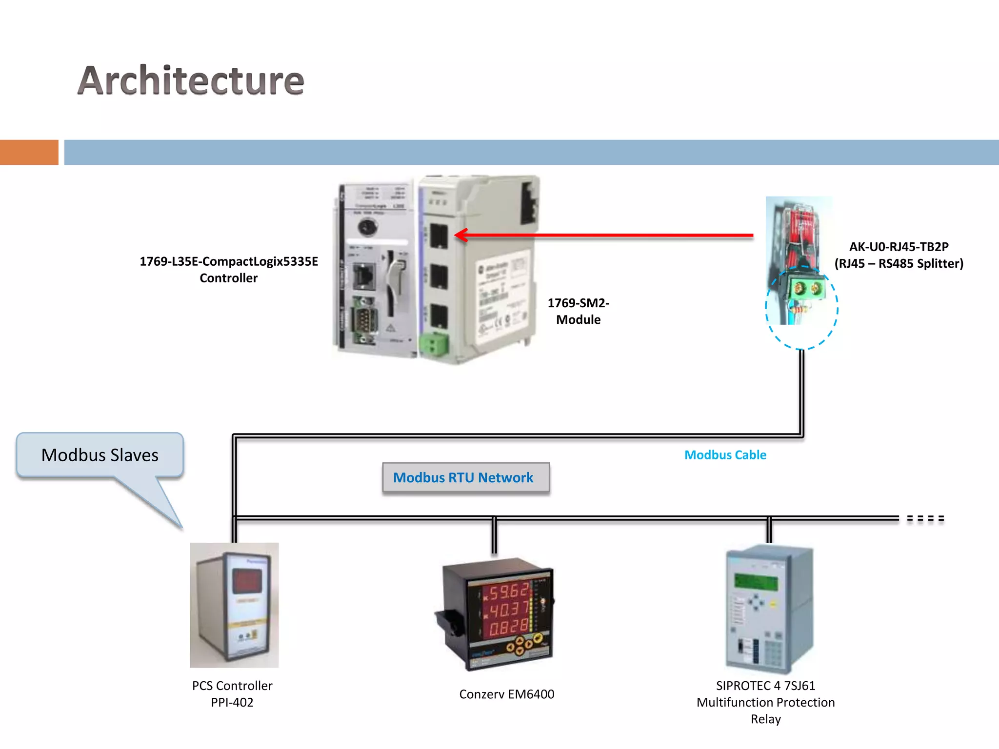
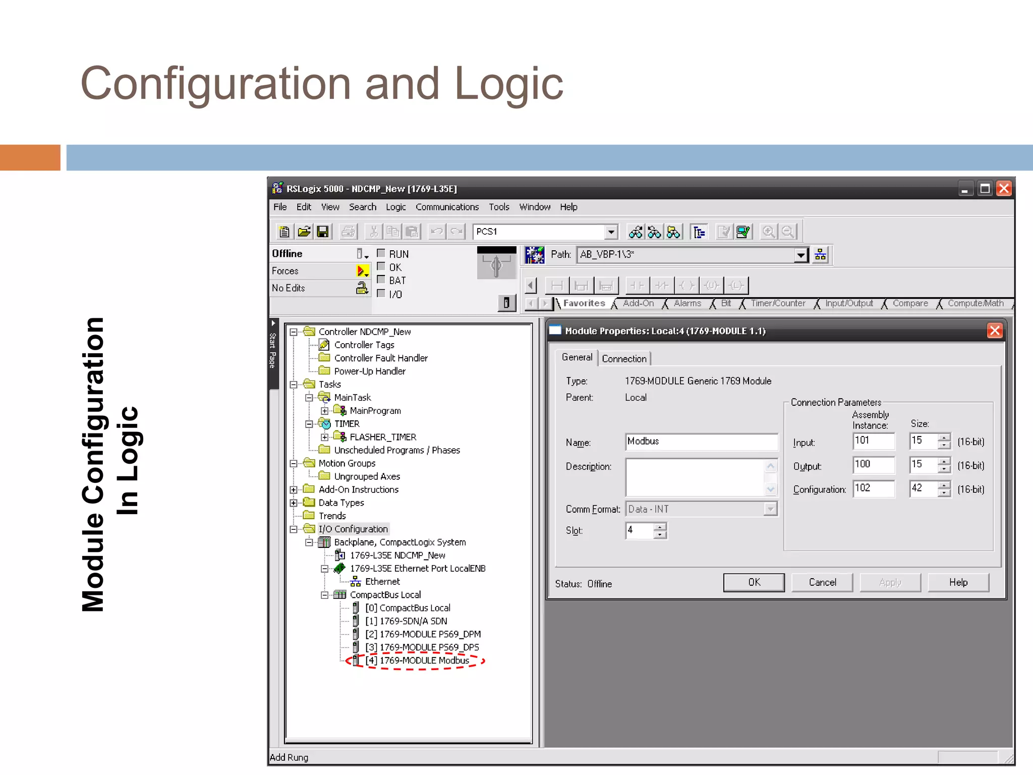
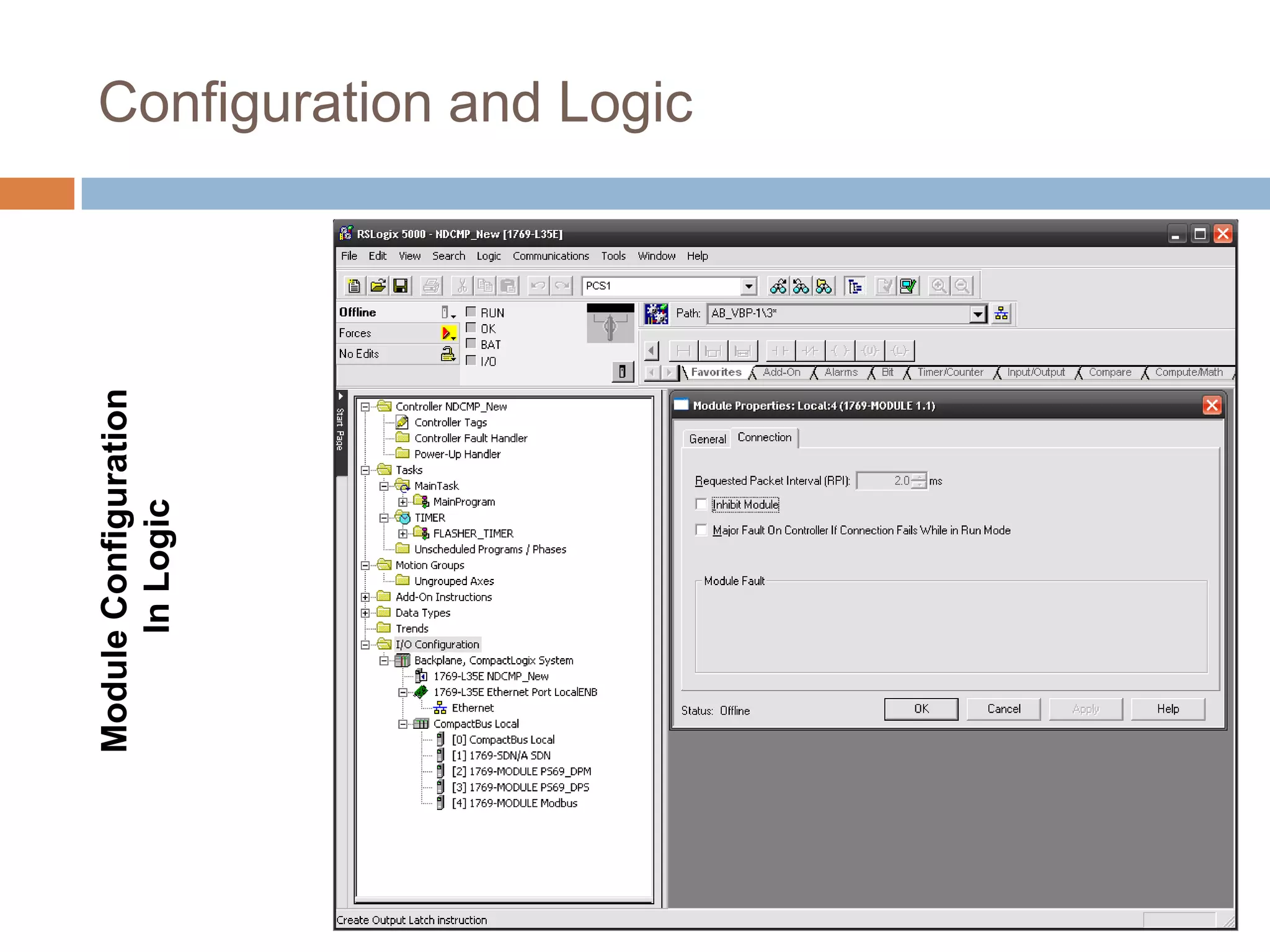
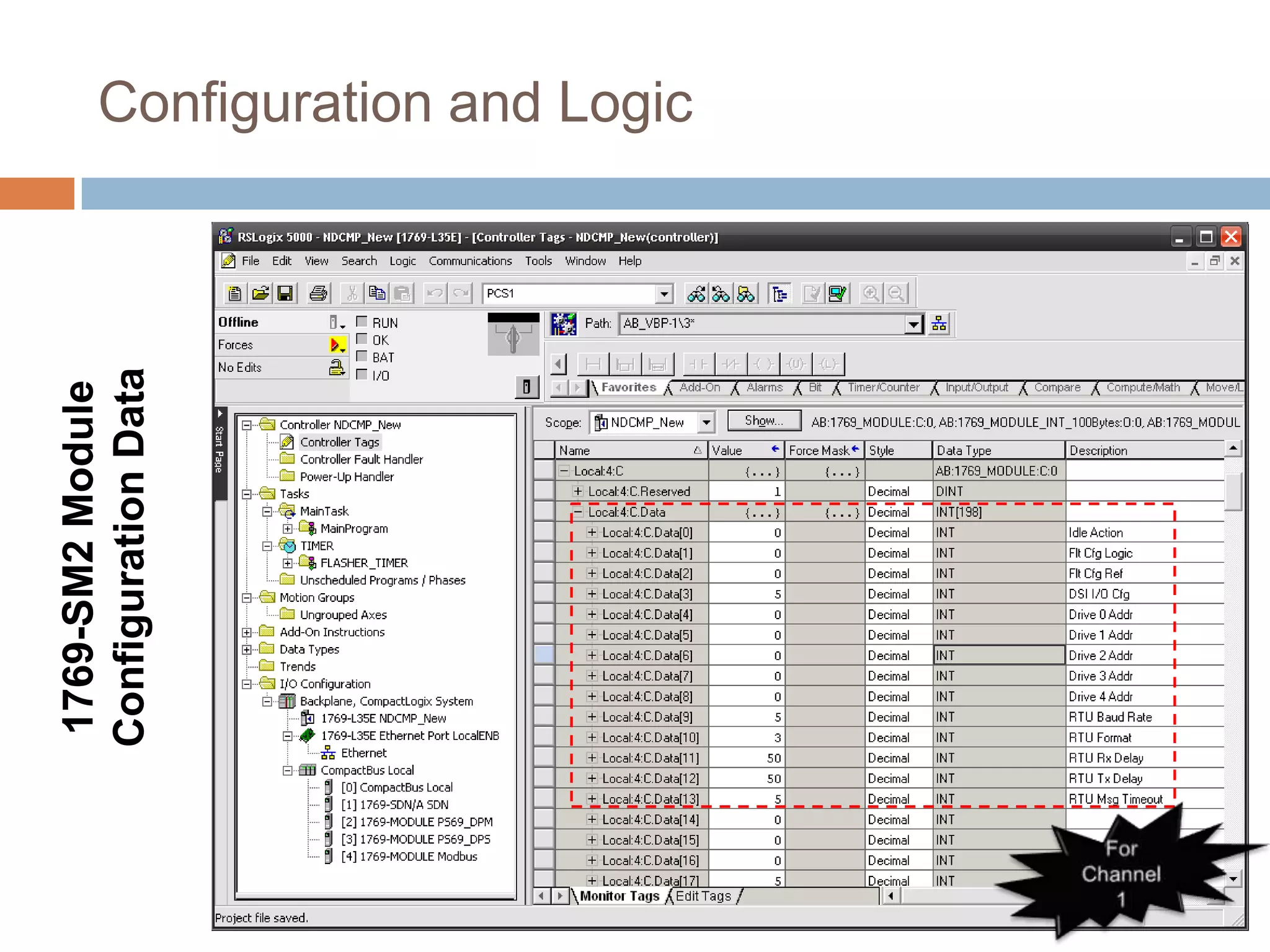
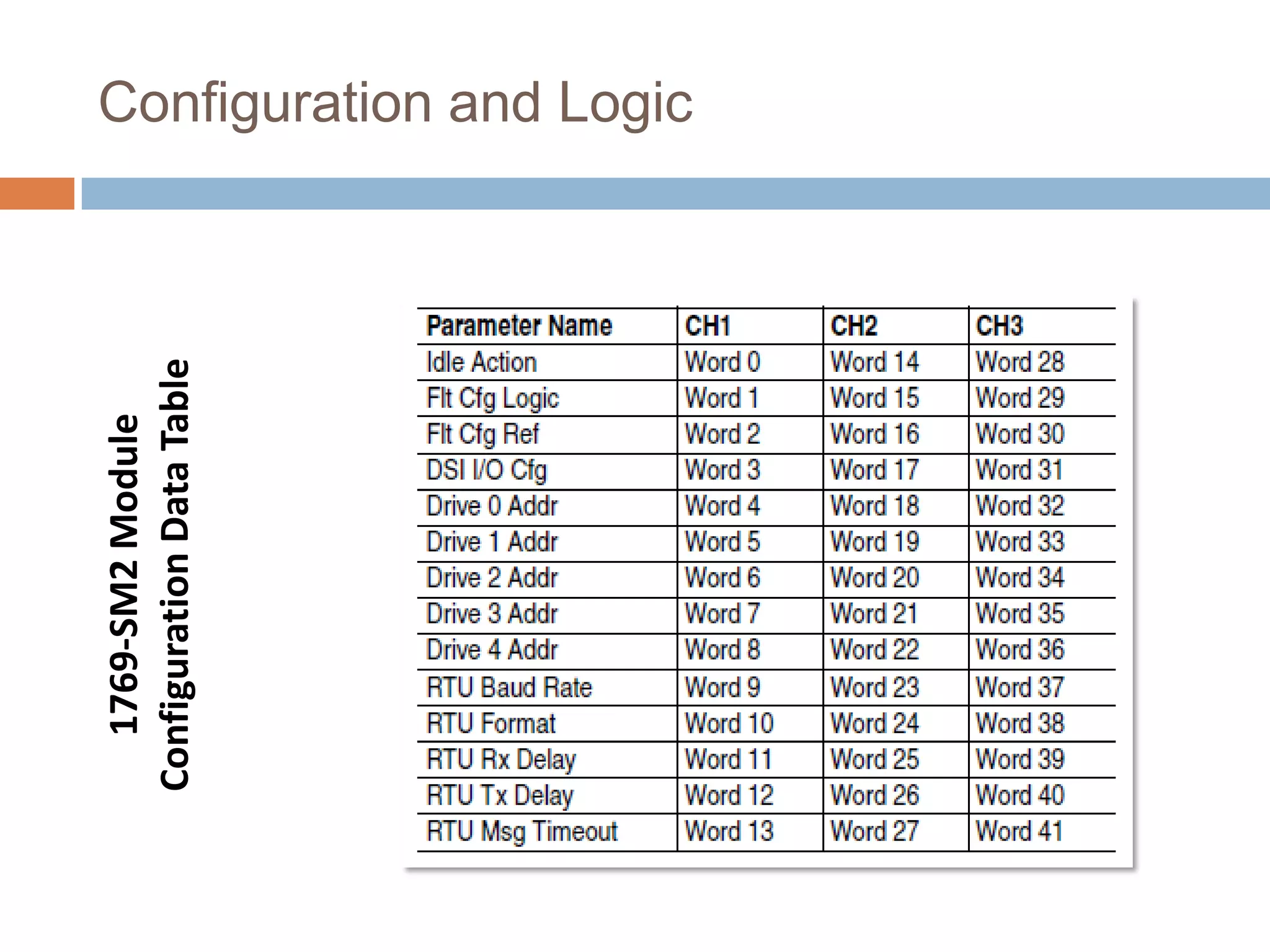
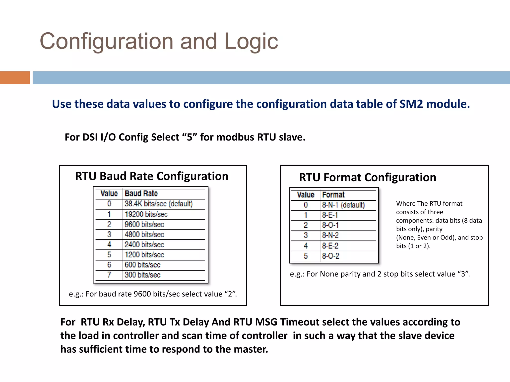
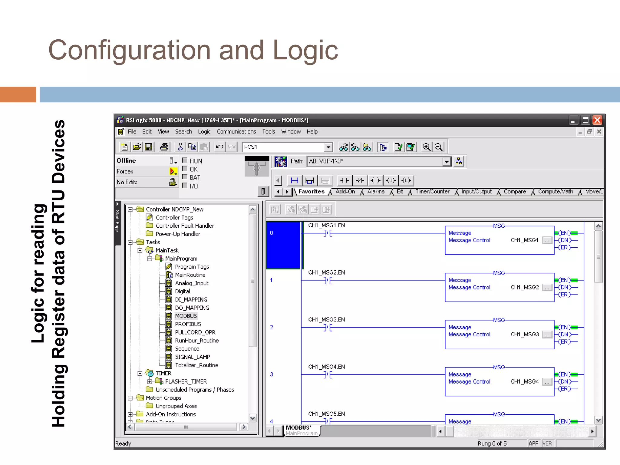
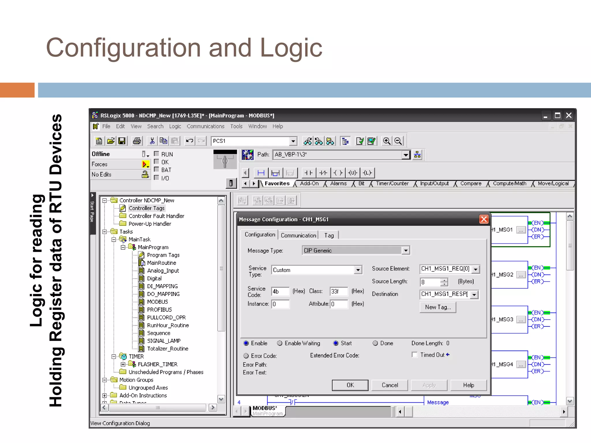
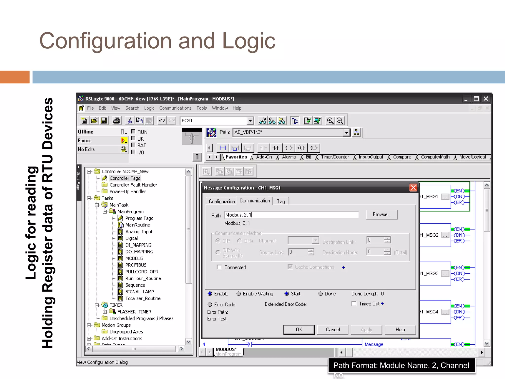
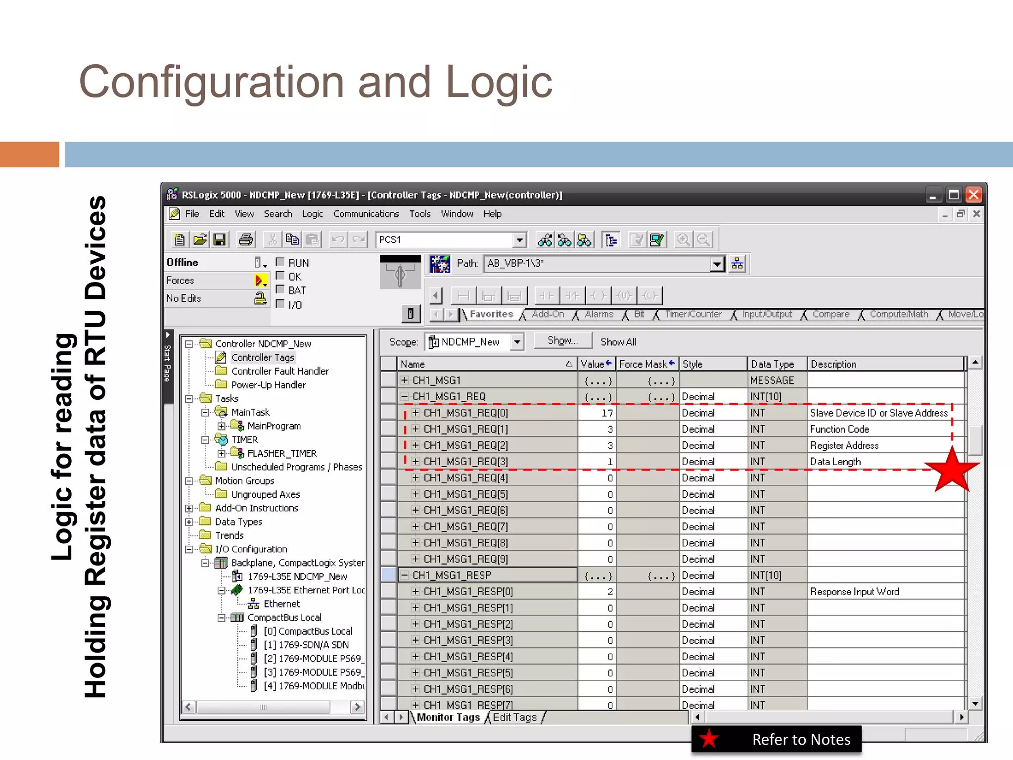
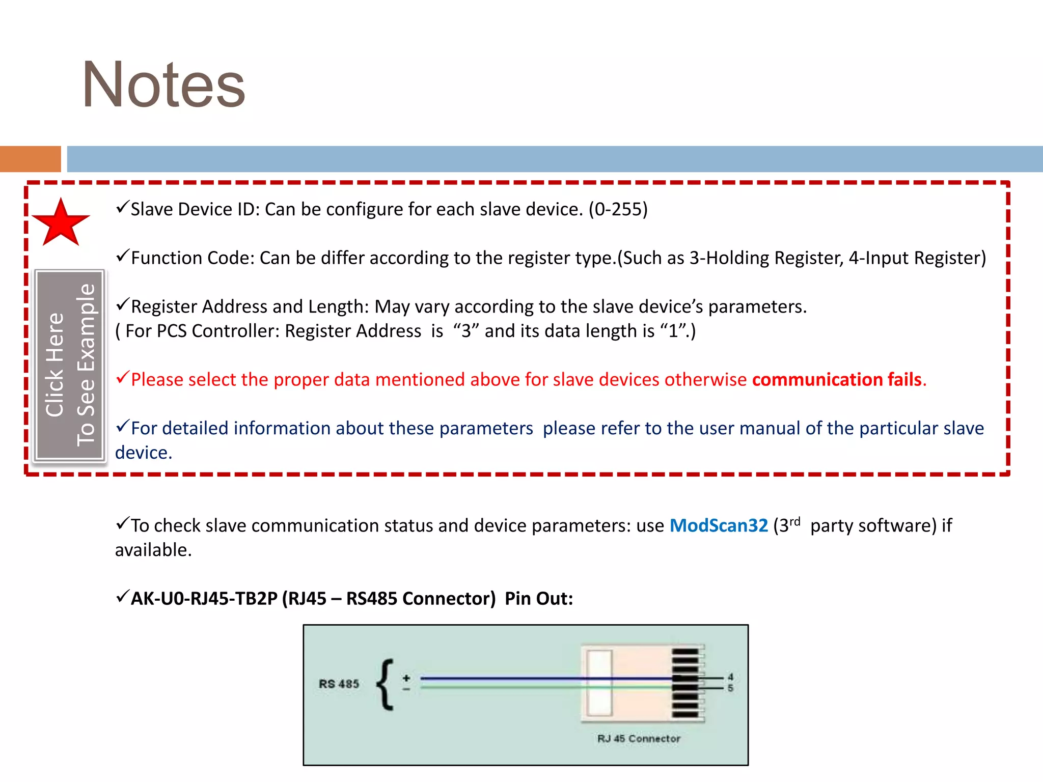
By:   Anish Shrivastava
AK-U0-RJ45-TB2P
          1769-L35E-CompactLogix5335E                                                            (RJ45 – RS485 Splitter)
                   Controller
                                                             1769-SM2-
                                                              Module


Modbus Slaves                                                            Modbus Cable
                                        Modbus RTU Network


                 PCS Controller                                             SIPROTEC 4 7SJ61
                                                Conzerv EM6400
                    PPI-402                                               Multifunction Protection
                                                                                   Relay
Setting the Configuration Mode Switch in 1769 SM2 Module


 Before installing the module, make sure its Configuration Mode Switch is correctly set.


   SW1 Setting         Description                                                    SW2 Setting
   CONT (Controller)   Default setting—The 1769-SM2 module uses the configuration
                                                                                      Single Position (For Single drive per
   back position       data downloaded from the controller on power-up and when the
                                                                                      channel)
                       controller is placed in run mode.
                                                                                      Multi-Drive Position (For Max 5
   PARAM (Parameter)   The 1769-SM2 module uses its internal parameter settings to
                                                                                      drives per channel or up 31 RTU
   front position      configure the module.
                                                                                      slave devices per channel)


   Select SW1 in Controller Position and SW2 in Multi-Drive Position.
Module Configuration
      In Logic
                       Configuration and Logic
Module Configuration
      In Logic
                       Configuration and Logic
1769-SM2 Module
Configuration Data
                     Configuration and Logic
1769-SM2 Module
Configuration Data Table
                           Configuration and Logic
Configuration and Logic

 Use these data values to configure the configuration data table of SM2 module.

   For DSI I/O Config Select “5” for modbus RTU slave.


     RTU Baud Rate Configuration                            RTU Format Configuration
                                                                                          Where The RTU format
                                                                                          consists of three
                                                                                          components: data bits (8 data
                                                                                          bits only), parity
                                                                                          (None, Even or Odd), and stop
                                                                                          bits (1 or 2).


                                                          e.g.: For None parity and 2 stop bits select value “3”.

    e.g.: For baud rate 9600 bits/sec select value “2”.


  For RTU Rx Delay, RTU Tx Delay And RTU MSG Timeout select the values according to
  the load in controller and scan time of controller in such a way that the slave device
  has sufficient time to respond to the master.
Logic for reading
Holding Register data of RTU Devices   Configuration and Logic
Logic for reading
Holding Register data of RTU Devices   Configuration and Logic
Configuration and Logic
Holding Register data of RTU Devices
         Logic for reading


                                          Path Format: Module Name, 2, Channel
                                          No.
Logic for reading
                 Holding Register data of RTU Devices   Configuration and Logic


Refer to Notes
Notes
                 Slave Device ID: Can be configure for each slave device. (0-255)

                 Function Code: Can be differ according to the register type.(Such as 3-Holding Register, 4-Input Register)
To See Example


                 Register Address and Length: May vary according to the slave device’s parameters.
   Click Here


                 ( For PCS Controller: Register Address is “3” and its data length is “1”.)

                 Please select the proper data mentioned above for slave devices otherwise communication fails.

                 For detailed information about these parameters please refer to the user manual of the particular slave
                 device.


                 To check slave communication status and device parameters: use ModScan32 (3rd party software) if
                 available.

                 AK-U0-RJ45-TB2P (RJ45 – RS485 Connector) Pin Out:
References
1769 SM 2 Module User Manual
http://literature.rockwellautomation.com/idc/groups/literature/documents/um/1769-um013_-en-p.pdf
THE
END

Modbus communication with 1769 sm2

  • 1.
    By: Anish Shrivastava
  • 2.
    AK-U0-RJ45-TB2P 1769-L35E-CompactLogix5335E (RJ45 – RS485 Splitter) Controller 1769-SM2- Module Modbus Slaves Modbus Cable Modbus RTU Network PCS Controller SIPROTEC 4 7SJ61 Conzerv EM6400 PPI-402 Multifunction Protection Relay
  • 3.
    Setting the ConfigurationMode Switch in 1769 SM2 Module Before installing the module, make sure its Configuration Mode Switch is correctly set. SW1 Setting Description SW2 Setting CONT (Controller) Default setting—The 1769-SM2 module uses the configuration Single Position (For Single drive per back position data downloaded from the controller on power-up and when the channel) controller is placed in run mode. Multi-Drive Position (For Max 5 PARAM (Parameter) The 1769-SM2 module uses its internal parameter settings to drives per channel or up 31 RTU front position configure the module. slave devices per channel) Select SW1 in Controller Position and SW2 in Multi-Drive Position.
  • 4.
    Module Configuration In Logic Configuration and Logic
  • 5.
    Module Configuration In Logic Configuration and Logic
  • 6.
    1769-SM2 Module Configuration Data Configuration and Logic
  • 7.
    1769-SM2 Module Configuration DataTable Configuration and Logic
  • 8.
    Configuration and Logic Use these data values to configure the configuration data table of SM2 module. For DSI I/O Config Select “5” for modbus RTU slave. RTU Baud Rate Configuration RTU Format Configuration Where The RTU format consists of three components: data bits (8 data bits only), parity (None, Even or Odd), and stop bits (1 or 2). e.g.: For None parity and 2 stop bits select value “3”. e.g.: For baud rate 9600 bits/sec select value “2”. For RTU Rx Delay, RTU Tx Delay And RTU MSG Timeout select the values according to the load in controller and scan time of controller in such a way that the slave device has sufficient time to respond to the master.
  • 9.
    Logic for reading HoldingRegister data of RTU Devices Configuration and Logic
  • 10.
    Logic for reading HoldingRegister data of RTU Devices Configuration and Logic
  • 11.
    Configuration and Logic HoldingRegister data of RTU Devices Logic for reading Path Format: Module Name, 2, Channel No.
  • 12.
    Logic for reading Holding Register data of RTU Devices Configuration and Logic Refer to Notes
  • 13.
    Notes Slave Device ID: Can be configure for each slave device. (0-255) Function Code: Can be differ according to the register type.(Such as 3-Holding Register, 4-Input Register) To See Example Register Address and Length: May vary according to the slave device’s parameters. Click Here ( For PCS Controller: Register Address is “3” and its data length is “1”.) Please select the proper data mentioned above for slave devices otherwise communication fails. For detailed information about these parameters please refer to the user manual of the particular slave device. To check slave communication status and device parameters: use ModScan32 (3rd party software) if available. AK-U0-RJ45-TB2P (RJ45 – RS485 Connector) Pin Out:
  • 14.
    References 1769 SM 2Module User Manual http://literature.rockwellautomation.com/idc/groups/literature/documents/um/1769-um013_-en-p.pdf
  • 15.