
More Related Content
Similar to WJ69产品说明书V1.1.pdf
Similar to WJ69产品说明书V1.1.pdf (20)
Recently uploaded
Recently uploaded (20)
WJ69产品说明书V1.1.pdf
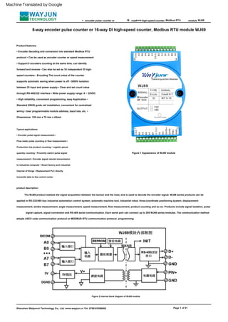
- 1. FROM Product features: • Encoder decoding and conversion into standard Modbus RTU protocol • Can be used as encoder counter or speed measurement • Support 8 encoders counting at the same time, can identify forward and reverse • Can also be set as 16 independent DI high- speed counters • Encoding The count value of the counter supports automatic saving when power is off • 3000V isolation between DI input and power supply • Clear and set count value through RS-485/232 interface • Wide power supply range: 8 ~ 32VDC • High reliability, convenient programming, easy Application • Standard DIN35 guide rail installation, convenient for centralized wiring • User programmable module address, baud rate, etc. • Dimensions: 120 mm x 70 mm x 43mm Figure 2 Internal block diagram of WJ69 module Modbus RTU Shenzhen Weijunrui Technology Co., Ltd. www.wayjun.cn Tel: 0755-83356002 8 16 The WJ69 product realizes the signal acquisition between the sensor and the host, and is used to decode the encoder signal. WJ69 series products can be applied in RS-232/485 bus industrial automation control system, automatic machine tool, industrial robot, three-coordinate positioning system, displacement measurement, stroke measurement, angle measurement, speed measurement, flow measurement, product counting and so on. Products include signal isolation, pulse signal capture, signal conversion and RS-485 serial communication. Each serial port can connect up to 255 WJ69 series modules. The communication method adopts ASCII code communication protocol or MODBUS RTU communication protocol. programming. high-speed counter, Typical applications: • Encoder pulse signal measurement • Flow meter pulse counting or flow measurement • Production line product counting • Logistic parcel quantity counting • Proximity switch pulse signal measurement • Encoder signal remote transmission to industrial computer • Smart factory and industrial Internet of things • Replacement PLC directly transmits data to the control center Figure 1 Appearance of WJ69 module module Page 1 of 21 WJ69 encoder pulse counter or road 8-way encoder pulse counter or 16-way DI high-speed counter, Modbus RTU module WJ69 product description: Machine Translated by Google
- 2. WJ69 - ÿ Configuration information such as state is stored in non-volatile memory EEPROM. FROM Communication interface: 1 standard RS-485 communication interface or 1 standard RS-232 communication interface, please specify when ordering. Communication protocol: supports two protocols, the character protocol defined by the command set and the MODBUS RTU communication protocol. The module automatically recognizes the commun General parameters of WJ69: (typical @ +25ÿ, Vs is 24VDC) Input type: Encoder AB signal input, 8 channels (A0/B0~ A7/B7). Low level: Input < 1V High level: Input 3.5 ~ 30V Frequency range 0-10KHz (all channels input at the same time), single channel can support 50KHz input. Encoder counting range - 2147483647 ~ +2147483647, automatically saved when power off DI counter range 0 ~ 4294967295, reset when power off Input resistance: 30Kÿ Communication: Protocol RS-485 or RS-232 standard character protocol and MODBUS RTU communication protocol Page 2 of 21 Modbus RTU It can realize network communication with various brands of PLC, RTU or computer monitoring system. Baud rate (2400, 4800, 9600, 19200, 38400, 57600, 115200bps) can be selected by software Address (0~255) can be selected by software Communication response time: 100 ms Maximum working power supply: +8 ~ 32VDC wide power supply range, internal Anti-reverse polarity and overvoltage protection circuit Power consumption: less than 1W 8-way encoder signal input or 16-way independent counter, can be connected to dry contact and wet contact, please refer to the wiring diagram for details. 8 16 Communication interface 485: output is RS-485 interface 232: output is RS-232 interface 2. Communication protocol Selection example 1: Model: WJ69-232 means the output is RS-232 interface Selection example 2: Model: WJ69-485 means the output is RS-485 interface The communication interface has high anti-interference design, ±15KV ESD protection, and the communication response time is less than 100mS. 3. Anti-jamming checksum can be set as required. There are transient suppression diodes inside the module, which can effectively suppress various surge pulses, protect the module, and internal digital filtering can also well suppress power frequency interference from the power grid. high-speed counter, WJ69 series products are designed and manufactured according to industrial standards, with no isolation between signal input and output, strong anti-interference ability and high reliability. Working temperature range - 45ÿÿ+85ÿ. Function introduction: WJ69 remote I/O module can be used to measure eight encoder signals, and can also be set as 16 independent counters or DI status measurement. 1. Signal input module Data format: 10 digits. 1 start bit, 8 data bits, 1 stop bit. No checksum. Communication address (0~255) and baud rate (2400, 4800, 9600, 19200, 38400, 57600, 115200bps) can be set; WJ69 encoder pulse counter or Shenzhen Weijunrui Technology Co., Ltd. www.wayjun.cn Tel: 0755-83356002 The longest distance of the network can be up to 1200 meters, connected by twisted-pair shielded cables. WJ69 series products are intelligent monitoring and control systems based on single-chip microcomputers, all user-set addresses, baud rates, data formats, checksums road product model: Machine Translated by Google
- 3. 9 NC empty pin 10 DATA+ RS-485 signal positive terminal B6 Encoder 6 signal B input terminal 19 B2 Encoder 2 signal B input terminal 16 4 12 PW+ Positive power supply 6 11 Modbus RTU B7 Encoder 7 signal B input terminal 21 A3 Encoder 3 signal A input terminal Pin Name Description 22 B3 Encoder 3 signal B input terminal Pin definition: pin name description WJ69 road 7 DICOM input signal common port Figure 3 WJ69 module wiring diagram 15 B0 Encoder 0 signal B input terminal 24 B4 Encoder 4 signal B input terminal B5 Encoder 5 signal B input terminal module B1 Encoder 1 signal B input terminal 26 DGND Signal ground table 1 pin definition 3 A6 Encoder 6 signal A input terminal 8 18 A2 Encoder 2 signal A input terminal 2 8 5V DATA- RS-485 signal negative terminal Page 3 of 21 20 DGND Signal ground 17 FROM 5 A7 Encoder 7 signal A input terminal 13 GND Negative terminal of power supply encoder pulse counter or 23 A4 Encoder 4 signal A input terminal 14 A0 Encoder 0 signal A input terminal Operating temperature: - 45 ~ +80°C Operating humidity: 10 ~ 90% (non- condensing) Storage temperature: - 45 ~ +80°C Storage humidity: 10 ~ 95% (non- condensing) Isolation withstand voltage: DI input and power supply 3000V isolation between the communication interface and the power supply. Dimensions: 120mm x 70mm x 43mm high-speed counter, 1 DGND Signal ground 16 A1 Encoder 1 signal A input terminal 5V power distribution Shenzhen Weijunrui Technology Co., Ltd. www.wayjun.cn Tel: 0755-83356002 25 A5 Encoder 5 signal A input terminal Machine Translated by Google
- 4. FROM road PNP type encoder Modbus RTU push-pull encoder NPN type encoder with pull-up resistor 8 16 NPN type encoder high-speed counter, level input Encoder signal input wiring diagram module Shenzhen Weijunrui Technology Co., Ltd. www.wayjun.cn Tel: 0755-83356002 WJ69 encoder pulse counter or Page 4 of 21 DI Counting Input Wiring Diagram Dry contact input Machine Translated by Google
- 5. The module enters the default state. In this state, the configuration of the module is as follows: FROM (Addr) The address code of the module, if not specified below, the value range is from 00 to FF (hexadecimal). 2- characters Modbus RTU (Command) Displays the command code or variable value. Variable length [data] Some data required by the output command. Variable Length [checksum] Checksum in parentheses indicates an optional parameter and is only required if checksum is enabled. 2- A control code used for character recognition, (cr) is used as the carriage return terminator, and its value is 0x0D. 1- character (cr) [Checksum] is required when checksum is enabled. It occupies 2-characters. Both commands and responses must have the checksum attribute attached. Checksums are used to check all input commands to help you spot host-to-module command errors and module-to-host response errors. The checksum character is placed after the command or response character and before the carriage return. Calculation method: two characters, a hexadecimal number, is the sum of the ASCII code values of all the characters sent before, and then ANDed with the hexadecimal number 0xFF. A character protocol command consists of a series of characters, such as a prefix, an address ID, variables, an optional checksum byte, and a command terminator (cr) to display. The host only commands one WJ69 module at a time, except the synchronous command with the wildcard address “**”. Command format: (Leading Code) (Addr)(Command)[data][checksum](cr) 8 16 Shenzhen Weijunrui Technology Co., Ltd. www.wayjun.cn Tel: 0755-83356002 (Leading code) The leading code is the first letter in the command. All commands need a command prefix, such as %,$,#,@,...etc. 1- character Page 5 of 21 A9=(0x21+0x30+0x30+0x30+0x32+0x30+0x36+0x30+0x30) AND 0xFF high-speed counter, The address code is 00, the baud rate is 9600 bps, and the checksum is prohibited. At this time, the parameters such as the baud rate, checksum status and other parameters of the WJ69 module can be modified through configuration commands. When you are not sure about the specific configuration of a certain module, you can also turn the INIT switch to the INIT position to make the module enter the default state, and then reconfigure the module. Response to command: Note: Please turn the INIT switch to the NORMAL position for normal use. module Application example: disable checksum (checksum) user command $002 (cr) module response ! 00020600 (cr) enable checksum (checksum) user command $002B6 (cr) module response ! 00020600 A9 (cr) '$' = 0x24 '0' = 0x30 '2' = 0x32 WJ69 encoder pulse counter or Reply messages depend on various commands. Responses also consist of several characters, including header codes, variables and end identifiers. The first response signal B6=(0x24+0x30+0x30+0x32) AND 0xFF ‘!’ = 0x21 ‘0’ = 0x30 ‘2’ = 0x32 ‘6’ = 0x36 WJ69 character protocol command set: The module’s factory initial settings are as follows: The address code is 01 The baud rate is 9600 bps The checksum is prohibited If the RS-485 network is used, a unique address code must be assigned, and the address code value is The hexadecimal number is between 00 and FF. Since the address codes of the new modules are the same, their addresses will be inconsistent with other modules, so when you build the system, you must reconfigure the address of each WJ69 module. You can modify the address of the WJ69 module through configuration commands after connecting the power cable of the WJ69 module and the RS485 communication cable. The baud rate and checksum status also need to be adjusted according to the user's requirements. Before modifying the baud rate and checksum state, the module must first enter the default state, otherwise it cannot be modified. The method to let the module enter the default state: There is an INIT switch on the side of the WJ69 module, which is on the side of the module. Turn the INIT switch to the INIT position, and then turn on the power, at this time road Machine Translated by Google
- 6. 2. Commands must be entered in capital letters. 3. (cr) represents the carriage return character on the keyboard, do not write it out directly, it should be the carriage return key (Enter key). FROM Description: Read the working mode of the encoder. Command format: $AA4(cr) Read the working mode of the encoder. Parameter description: AA module address, the value range is 00~FF (hexadecimal). The factory address is 01, converted into hexadecimal as the ASCII code of each character. For example, the address 01 is changed to 30H and 31H in hexadecimal. (cr) Terminator, enter key of upper computer, 0DH in hexadecimal system. Modbus RTU Response format: ! BBBBBBBB (cr) represents the working mode of 8 encoder channels, 8 numbers, and the sequence is encoder 7~encoder 0, Response format: ! AA(cr) means the setting is successful Parameter description: BBBBBBBB represents the working mode of 8 encoder channels, 8 numbers, the order of arrangement is encoder 7~encoder 0, the value is 0: working mode 0; the value is 1: Working mode 1 Application example: User command (character format) $01311110000 (cr) Module response (character format) ! 01(cr) Description: Set encoder 7~encoder 4 to work mode 1, set encoder 3~encoder Device 0 is working mode 0 8 16 Page 6 of 21 2. Read the working mode of the encoder 3. Read switch state command description: read back the switch state of all encoder input channels from the module. Command format: #AA(cr) Parameter description: # delimiter. Hexadecimal is 23H AA module address, the value range is 00ÿFF (hexadecimal). The factory address is 01, converted into hexadecimal as ASCII for each character 1. Set the working mode of the encoder Description: set the working mode of the encoder, 0 or 1, the factory default is 0. After the working mode is modified, the module must be restarted to take effect. high-speed counter, code. For example, the address 01 is changed to 30H and 31H in hexadecimal. (cr) Terminator, enter key of upper computer, 0DH in hexadecimal system. Response format: > CCCCCCCC,DDDDDDDD (cr) command is valid. ? 01(cr) Invalid command or illegal operation. Parameter description: > delimiter. The hexadecimal system is 3EH CCCCCCCC represents the read encoder input switch state, 8 numbers, and the sequence is B7A7 B6A6 B5A5 B4A4, Working mode 0: Encoder AB signal input Working mode 1: Two independent counter inputs Note: The following command note (working mode 0) indicates that the data is valid only when the working mode of the encoder is 0. The remark (working mode 1) indicates that the data is valid only when the encoder working mode is 1. Command format: $AA3BBBBBBBB(cr) Set the working mode of the encoder. It will take effect after reboot. Parameter description: AA module address, the value range is 00~FF (hexadecimal). The factory address is 01, converted into hexadecimal as the ASCII code of each character. For example, the address 01 is changed to 30H and 31H in hexadecimal. (cr) Terminator, enter key of upper computer, 0DH in hexadecimal system. module Value 0: working mode 0; value 1: working mode 1 WJ69 encoder pulse counter or Shenzhen Weijunrui Technology Co., Ltd. www.wayjun.cn Tel: 0755-83356002 Application example: User command (character format) $014(cr) module response (character format) ! 11110000 (cr) Description: encoder 7~encoder 4 is working mode 1, encoder 3~encoder 0 is working mode 0 There are two codes, '!' or '>' for valid commands and '?' for invalid commands. By checking the response information, you can monitor whether the command is valid. Note: 1. In some cases, many commands use the same command format. Make sure that the address you use is correct in a command, if you use the wrong address, and this address represents another module, then the command will take effect in the other module, thus generating an error. road Machine Translated by Google
- 7. Shenzhen Weijunrui Technology Co., Ltd. www.wayjun.cn Tel: 0755-83356002 , N means read encoder N counter data command. (cr) Terminator, enter key of upper computer, 0DH in hexadecimal system. Response format: !+AAAAAAAAAA(cr) Application example 1: User command (character format) #012(cr) module response (character format) !+0012345678, +0012345678, +0012345678, +0012345678, +0012345678, 16 Modbus RTU Description: Read the data of the encoder counter, you can read all encoders, or you can read a single encoder. '+' means forward rotation, '-' means reverse rotation. Command format: #AA2(cr) 5. Read the encoder input frequency command (working mode 0) description: read the frequency input by the encoder, you can read all encoders, and you can also read a single encoder. '+' means forward rotation, '-' means reverse rotation. Command format: #AA3 WJ69 AA Module address, the value range is 00~FF (hexadecimal). The factory address is 01, converted into hexadecimal as ASCII for each character AA Module address, the value range is 00~FF (hexadecimal). The factory address is 01, converted into hexadecimal as ASCII for each character road A6: low level B6: low level A7: low level B7: low level The input switch status of the module is 00000111 and the arrangement order is B3A3 B2A2 B1A1 B0A0 A0: high level B0: high level A1: high level B1: low level +AAAAAAAAAA, +AAAAAAAAAA, +AAAAAAAAAA, +AAAAAAAAAA (cr) module The order of arrangement is B7A7 B6A6 B5A5 B4A4 AA Module address, the value range is 00~FF (hexadecimal). The factory address is 01, converted into hexadecimal as ASCII for each character 3 means read encoder 0~encoder 7 to input frequency command. (cr) Terminator, enter key of upper computer, 0DH in hexadecimal system. Response format: !+AAAAAA.AA,+AAAAAA.AA,+AAAAAA.AA,+AAAAAA.AA, +AAAAAA.AA, +AAAAAA.AA, +AAAAAA.AA,+AAAAAA.AA (cr) Command format: # AA3N Read encoder N input frequency 8 , code. For example, the address 01 is changed to 30H and 31H in hexadecimal. 2 means read counter data command. Page 7 of 21 +0012345678, +0012345678, +0012345678 (cr) Explanation: The count value of all encoders is forward +12345678 Application example 2: User command (character format) #0120(cr) Module response (character format) !-0012345678(cr ) Description: The count value of encoder 0 is inverted -12345678. 4. Read encoder counter data command (working mode 0) FROM encoder pulse counter or DDDDDDDD represents the read encoder input switch status, 8 numbers, the arrangement order is B3A3 B2A2 B1A1 B0A0, value 0: input low level; value 1: input high level (cr) terminator, the host computer returns Car key, the hexadecimal value is 0DH. Application example: User command (character format) #01(cr) Module response (character format) >00001010,00000111(cr) Description: The module input switch status is 00001010 A4: low level B4: high level A5: low level B5: high level code. For example, the address 01 is changed to 30H and 31H in hexadecimal. high-speed counter, A2: low level B2: low level A3: low level B3: low level Command format: #AA2N(cr) read channel N count value code. For example, the address 01 is changed to 30H and 31H in hexadecimal. 2 means read encoder 0~encoder 7 counter data command. (cr) Terminator, enter key of upper computer, 0DH in hexadecimal system. Response format: !+AAAAAAAAAA, +AAAAAAAAAA, +AAAAAAAAAA, +AAAAAAAAAA, Machine Translated by Google
- 8. road code. For example, the address 01 is changed to 30H and 31H in hexadecimal. 3 means read input frequency command. FROM code. For example, the address 01 is changed to 30H and 31H in hexadecimal. Modbus RTU 4 means read encoder 0~encoder 7 to input speed command. (cr) Terminator, enter key of upper computer, 0DH in hexadecimal system. Response format: !+AAAAA,+AAAAA,+AAAAA,+AAAAA, +AAAAA,+AAAAA,+AAAAA,+AAAAA (cr) Command format: #AA8N read encoder N input speed Response format: ! AA(cr) indicates successful setting Application example 1: User command (character format) $0113+0000000000(cr) module response (character format) ! 01(cr) Shenzhen Weijunrui Technology Co., Ltd. www.wayjun.cn Tel: 0755-83356002 8 !+001000.00,+001000.00,+001000.00,+001000.00,+001000.00, +001000.00, +001000.00,+001000.00 (cr) Explanation: The input frequency value of all encoders is forward rotation +1KHz. Application example 2: User command (character format) #0130(cr) Module response (character format) !-001000.00(cr) Explanation: The input frequency value of encoder 0 is inverted -1KHz. When means setting the count value of all encoders at the same time. 16 6. Read the encoder input speed command (working mode 0) Description: read the encoder input speed, you can read all encoders, and you can also read a single encoder. '+' means forward rotation, '-' means reverse rotation. Command format: #AA4 AA module address, value range 00ÿFF (hexadecimal). The factory address is 01, converted into hexadecimal as ASCII for each character Parameter description: AA module address, the value range is 00~FF (hexadecimal). The factory address is 01, converted into hexadecimal as the ASCII code of each character. For example, the address 01 is changed to 30H and 31H in hexadecimal. (cr) Terminator, enter key of upper computer, 0DH in hexadecimal system. N means read encoder N input speed command. (cr) Terminator, enter key of upper computer, 0DH in hexadecimal system. high-speed counter, N means read encoder N input frequency command. (cr) Terminator, enter key of upper computer, 0DH in hexadecimal system. Response format: ! +AAAAAA.AA (cr) Application example 1: User command (character format) #013(cr) Response format: ! +AAAAA (cr) Application example 1: User command (character format) #014(cr) module response (character format) !+01000,+01000,+01000,+01000 (cr) Description: all encoders The input speed value is forward rotation + 1000 rotations. Application example 2: User command (character format) #0140(cr) Module response (character format) !-01000(cr) Explanation: The input speed value of encoder 0 is reverse -1000 rpm. module module response (character format ) WJ69 AA Module address, the value range is 00~FF (hexadecimal). The factory address is 01, converted into hexadecimal as ASCII for each character 7. Command to modify the value of the encoder counter (working mode 0) Explanation: modify the value of the encoder counter, and it can also be set to zero to restart counting. Command format: $AA1N+AAAAAAAAAA(cr) Modify the count value of encoder N, N is the code number of the encoder, the value is 0 ~ 7, set N to 'M' encoder pulse counter or AA Module address, the value range is 00~FF (hexadecimal). The factory address is 01, converted into hexadecimal as ASCII for each character code. For example, the address 01 is changed to 30H and 31H in hexadecimal. 4 means read the input speed command. Page 8 of 21 Machine Translated by Google
- 9. 8. Set the number of pulses per revolution of the encoder (working mode 0) FROM 9. Read the number of pulses per revolution of the encoder (working mode 0) Page 9 of 21 Modbus RTU Description: Reads the pulses per revolution of all encoders. Command format: $AA6(cr) Read the number of pulses per revolution of all encoders, and the sequence is 0~7. Parameter description: AA module address, the value range is 00~FF (hexadecimal). The factory address is 01, converted into hexadecimal as the ASCII code of each character. For example, the address 01 is changed to 30H and 31H in hexadecimal. (cr) Terminator, enter key of upper computer, 0DH in hexadecimal system. AAAAA represents the number of pulses, such as 1000, 800 or 600, etc. (cr) Terminator, enter key of upper computer, 0DH in hexadecimal system. 8 16 Response format: ! AA(cr) indicates successful setting Application example: User command (character format) $01S0(cr) module response (character format) ! 01(cr) Response format: ! AA(cr) indicates successful setting Application example: User command (character format) $015100300(cr) Module response (character format) ! 01(cr) Explanation: Set the number of pulses per revolution of encoder 1 to 300. Shenzhen Weijunrui Technology Co., Ltd. www.wayjun.cn Tel: 0755-83356002 10. Set whether the encoder count value is automatically saved when power is off (working mode 0) Description: Set whether the encoder count value is automatically saved when power is off. The factory default value is 1 (auto save). Command format: $AASW (cr) Set whether the encoder is automatically saved when the power is off. Parameter description: AA module address, the value range is 00~FF (hexadecimal). The factory address is 01, converted into hexadecimal as the ASCII code of each character. For example, the address 01 is changed to 30H and 31H in hexadecimal. Description: Set the number of pulses per revolution of the encoder. Set according to the parameters of the connected encoder. The factory default value is 1000. The encoder speed can only be read after setting the correct number of pulses. Command format: $AA5NAAAAA (cr) Set the number of pulses per revolution of the encoder. Parameter description: AA module address, the value range is 00~FF (hexadecimal). The factory address is 01, converted into hexadecimal as the ASCII code of each character. For example, the address 01 is changed to 30H and 31H in hexadecimal. 5 Set the pulses per revolution command of the encoder. high-speed counter, S Set whether to automatically save the command when the encoder is powered off. N Encoder code, value 0 ~ 7. module Response format: ! AAAAA, AAAAA, AAAAA, AAAAA, AAAAA, AAAAA, AAAAA, AAAAA (cr) Indicates the number of pulses per revolution of encoder 0~encoder 7. WJ69 encoder pulse counter or W 0: Do not automatically save; 1: Automatically save the encoder count value when power off. (cr) Terminator, enter key of upper computer, 0DH in hexadecimal system. Application example: User command (character format) $016(cr) module response (character format) ! 01000, 01000, 01000, 01000, 01000, 01000, 01000, 01000 (cr) Description: The number of pulses per revolution of all encoders is 1000. Description: Set the count value of encoder 3 to 0. Application example 2: User command (character format) $011M+0000000000(cr) Module response (character format) ! 01(cr) Explanation: Set the count value of all encoders to 0. Application example 3: User command (character format) $011M+0000003000(cr) Module response (character format) ! 01(cr) Explanation: Set the count value of all encoders to +3000. road Machine Translated by Google
- 10. Page 10 of 21 Response format: !AAAAAAAAAA, AAAAAAAAAA, AAAAAAAAAA, AAAAAAAAAA, AAAAAAAAAA, AAAAAA ÿÿÿÿÿ!AAAAAA.AA,AAAAAA.AA,AAAAAA.AA,AAAAAA.AA,AAAAAA.AA,AAAAAA.AA,AAAAAA 16 Modbus RTU AA Module address, the value range is 00~FF (hexadecimal). The factory address is 01, converted into hexadecimal as ASCII for each character AA Module address, the value range is 00~FF (hexadecimal). The factory address is 01, converted into hexadecimal as ASCII for each character code. For example, the address 01 is changed to 30H and 31H in hexadecimal. 6 means read input frequency command. code. For example, the address 01 is changed to 30H and 31H in hexadecimal. 5 means read counter data command. WJ69 11. Read counter data command (working mode 1) road 12. Read input frequency command (working mode 1) module AA Module address, the value range is 00~FF (hexadecimal). The factory address is 01, converted into hexadecimal as ASCII for each character code. For example, the address 01 is changed to 30H and 31H in hexadecimal. Shenzhen Weijunrui Technology Co., Ltd. www.wayjun.cn Tel: 0755-83356002 8 code. For example, the address 01 is changed to 30H and 31H in hexadecimal. 5 indicates the command to read the counter data of channel A0~channel B7. The order of arrangement is A0, B0, ~ ~ ~ , A7, B7. (cr) Terminator, enter key of upper computer, 0DH in hexadecimal system. 6 means read channel A0~channel B7 input frequency command. (cr) Terminator, enter key of upper computer, 0DH in hexadecimal system. A.AA,AAAAAA.AA,AAAAAA.AA,AAAAAA.AA,AAAAAA.AA,AAAAAA.AA,AAAAAA.AA,AAAA AA.AA,AAAAAA.AA, AAAAAA.AA (cr) Command formatÿ #AA6N Read channel N input frequency. AAAA, AAAAAAAAA, AAAAAAAAA, AAAAAAAAA, AAAAAAAAA, AAAAAAAAA, AAAAAAAAA, AAAAAAAAA, AAAAAAAAA, AAAAAAAAA, AAAAAAAAA (cr) Command Formatÿ#AA5N(cr) FROM encoder pulse counter or Description: Set the encoder not to save the count value, and the count will be automatically cleared after power off. N means read channel N input frequency command. N value: 0123456789ABCDEF, corresponding to A0~B7 (cr) terminator, upper computer Enter key, hexadecimal is 0DH. Response format: !AAAAAA.AA (cr) Application example 1: User command (character format) #016(cr) high-speed counter, Description: To read the data of the counter, you can read all channels or a single channel. Command format: #AA5(cr) Description: Read the input frequency, you can read all channels, and you can also read a single channel. Command format: #AA6 AA module address, value range 00ÿFF (hexadecimal). The factory address is 01, converted into hexadecimal as ASCII for each character N means read channel N counter data command. N value: 0123456789ABCDEF, corresponding to A0~B7 (cr) terminator, upper computer Enter key, hexadecimal is 0DH.ÿÿÿÿÿ!AAAAAAAAAA(cr) ÿÿÿÿ1ÿ ÿÿÿÿÿÿÿÿÿÿ #015(cr)ÿÿÿÿ ÿÿÿÿÿÿ !0012345678, 0012345678, 0012345678, 0012345678, 0012345678, 0012345678, 0012345678, 0012345678, 0012345678, 0012345678, 0012345678, 0012345678, 0012345678, 0012345678, 0012345678, 0012345678 (cr) Description: The count value of all channels is 12345678. Application example 2: User command (character format) #015F(cr) Module response (character format) !0012345678(cr) Explanation: The count value of channel B7 is 12345678. Machine Translated by Google
- 11. FROM 13. Modify the value command of DI counter (working mode 1) 14. Set the counting mode of the DI counter (working mode 1) Description: Set whether the DI counter counts on the rising edge or the falling edge. The factory setting is 00000000, 00000000. The default is rising edge counting Modbus RTU The settings take effect after the module restarts. Parameter description: AA module address, the value range is 00~FF (hexadecimal). The factory address is 01, converted into hexadecimal as the ASCII code of each character. For example, the address 01 is changed to 30H and 31H in hexadecimal. (cr) Terminator, enter key of upper computer, 0DH in hexadecimal system. Response format: ! AA(cr) means the setting is successful Application example 1: User command (character format) $012F+0000000000(cr) Module response (character format) ! 01(cr) Explanation: Set the count value of channel B7 to 0. 8 16 Shenzhen Weijunrui Technology Co., Ltd. www.wayjun.cn Tel: 0755-83356002 Application example 2: User command (character format) $012M+0000000000(cr) Module response (character format) ! 01(cr) Explanation: Set the count value of all channels to 0. Application example 3: User command (character format) $012M+0000003000(cr) Module response (character format) ! 01(cr) Explanation: Set the count value of all channels to +3000. Page 11 of 21 Module response (character format) ! 01(cr) Description: Set B7~A6 channel falling edge counting, set B5~A2 channel rising edge counting, set B1~A0 channel falling edge counting. high-speed counter, Description: Modify the value of DI counter, or set it to zero to restart counting. Command format: $AA2N+AAAAAAAAAA(cr) Modify the count value of counter N, N is the counter code, the value is 0123456789ABCDEF, 15. Read the counting mode of the DI counter (working mode 1) Corresponding to A0~B7, setting N to 'M' means setting the count values of all channels at the same time. module Command format: $AA7AAAAAAAA,BBBBBBBB(cr) Set the counting mode of DI counter. Parameter description: AA module address, the value range is 00~FF (hexadecimal). The factory address is 01, converted into hexadecimal as the ASCII code of each character. For example, the address 01 is changed to 30H and 31H in hexadecimal. (cr) Terminator, enter key of upper computer, 0DH in hexadecimal system. WJ69 encoder pulse counter or Description: Read whether the DI counter is counting on the rising edge or falling edge. Command format: $AA8(cr) Read the counting mode of DI counter. Parameter description: AA module address, the value range is 00~FF (hexadecimal). The factory address is 01, converted into hexadecimal as ASCII for each character Response format: ! AA(cr) means the setting is successful Parameter description: AAAAAAAA represents the channel state, 8 numbers, the order of arrangement is B7A7 B6A6 B5A5 B4A4, BBBBBBBB represents the channel state, 8 numbers, the order of arrangement is B3A3 B2A2 B1A1 B0A0, the value is 0: counting on the rising edge of the channel; value 1: counting on the falling edge of the channel Application example: User command (character format) $01711110000,00001111(cr) Module response (character format) ! 001000.00,001000.001000.001000.001000.001000.001000.00, 001000.001000.001000.001000.001000.001000.001000.001000.001000.00,00,0000.00,00,001000.00 00.00 00.00 00.00 . 1KHz. Application example 2: User command (character format) #016E(cr) Module response (character format) !001000.00(cr) Description: The input frequency value of channel A7 is 1KHz. road Machine Translated by Google
- 12. FROM BBBBBBBB represents the channel status, 8 numbers, the arrangement order is B3A3 B2A2 B1A1 B0A0, the value is 0: the rising edge counting of this channel; the value is 1: the falling edge counting of this channel Application example: User command (character format) $018(cr) module Response (character format) ! 11110000,00001111 (cr) Description: B7~A6 channel falling edge counting, B5~A2 channel rising edge counting, B1~A0 channel falling edge counting. 17. Read the filter time of DI (working mode 1) Description: read the filter time of all DI channels. Command format: $01LR reads the filter time of all DIs, and the sequence is A0, B0, ~ ~ ~ , A7, B7. Response format: ! AAAAA, AAAAA, AAAAA, AAAAA, AAAAA, AAAAA, AAAAA, AAAAA, AAAAA, AAAAA, AAAAA, AAAAA, AAAAA, AAAAA, AAAAA, AAAAA indicates the filter time of A0, B0, ~ ~ ~ , A7, B7 . Application example: User command (character format) $01LR module response (character format) ! 00020, 00020, 00020, 00020, 00020, 00020, 00020, 00020, 00020, 00020, 00020, 00020, 00020, 00020, 0002 ( cr) Note: The filter time of all DI channels is 20mS. Modbus RTU 18. Set all the parameters set by the above character command to restore the factory settings. Note: The parameters set by the module using the above character commands are restored to the factory settings, and the module restarts automatically after completion. Command format: $AA900(cr) Set parameters to restore factory settings. Parameter description: AA module address, the value range is 00~FF (hexadecimal). The factory address is 01, converted into hexadecimal as the ASCII code of each character. For example, the address 01 is changed to 30H and 31H in hexadecimal. (cr) Terminator, enter key of upper computer, 0DH in hexadecimal system. Command format: $01LWNAAAAA Set the filter time of DI channel N. N is the counter code, the value is 0123456789ABCDEF, corresponding to A0~B7, 8 16 Setting N to 'M' means setting the filter time of all channels at the same time. AAAAA represents the filter time, such as 0, 20 or 50, etc. Response format: ! 01(cr) means the setting is successful Application example: User command (character format) $01LW100020 Module response (character format) ! 01(cr) Explanation: Set the filter time of B0 to 20, that is, 20mS. Shenzhen Weijunrui Technology Co., Ltd. www.wayjun.cn Tel: 0755-83356002 high-speed counter, 16. Set the filter time of DI (working mode 1) Description: Set the filter time of DI. 1 means 1mS, and the factory default is 0. Photoelectric switch input is set to 0, mechanical switch or relay input Page 12 of 21 It is recommended to set it to 20~100. The settings will take effect after restarting. module Response format: ! AA(cr) means the setting is successful, and the module will restart automatically. Application example: User command (character format) $01900 Module response (character format) ! 01(cr) Explanation: The parameters are restored to factory settings. WJ69 encoder pulse counter or 19. Configure WJ69 module command description: set address, baud rate, checksum status for a WJ69 module. Configuration information is stored in non-volatile memory EEPROM. Command format: %AANNTTCCFF(cr) Parameter description: % delimiter. code. For example, the address 01 is changed to 30H and 31H in hexadecimal. (cr) Terminator, enter key of upper computer, 0DH in hexadecimal system. Response format: !AAAAAAAA,BBBBBBBB (cr) Indicates the counting mode of DI counter. Parameter description: AAAAAAAAA represents the channel status, 8 numbers, the arrangement order is B7A7 B6A6 B5A5 B4A4, road Machine Translated by Google
- 13. Table 2 Baud rate code 10: Hexadecimal complement (Twos complement) (cr) terminator, upper computer Enter key, hexadecimal is 0DH. Response format: !AA(cr) command is valid. ?AA(cr) command invalid or illegal operation, or the configuration jumper was not installed before changing the baud rate or checksum. Parameter description: ! Delimiter, indicating that the command is valid. ? Delimiter, indicating that the command is invalid. Other instructions: If you configure the module for the first time, AA=00, NN is equal to the new address. If the reconfiguration module changes the address, input range, and data format, AA equals the currently configured address, and NN equals the current or new address. If you want to reconfigure the module to change the baud rate or checksum state, you must install the configuration jumper to make the module enter the default state. At this time, the module address is 00H, that is, AA=00H, and NN is equal to the current or new address. If the format is wrong or the communication is wrong or the address does not exist, the module will not respond. Application example: User command %0011000600(cr) Module response ! 11(cr) Explanation: % delimiter. 04 4800 baud 16 Bit2 Bit 0 Modbus RTU 06 19200 baud Shenzhen Weijunrui Technology Co., Ltd. www.wayjun.cn Tel: 0755-83356002 38400 baud 07 WJ69 NN represents the hexadecimal address of the new module, and the value of NN ranges from 00 to FF. road Table 3 Data format, checksum code Page 13 of 21 09 module CC represents the baud rate code in hexadecimal. baud rate 115200 baud 8 Baud rate code 2400 baud FF uses 8 hexadecimal bits to represent the data format and checksum. Note that bits2 to bits5 do not have to be set to zero. Bit7 Bit 6 Bit 5 Bit 4 Bit 3 Bit1-bit0: data format bits. 00: Engineering Units AA represents the terminator of the input module address (cr), the upper computer enter key, and the hexadecimal value is 0DH. 9600 baud 05 FROM Bit 1 00 means the original address of the WJ69 module you want to configure is 00H. 11 means the hexadecimal address of the new module is 11H. 00 type code, WJ69 product must be set to 00. 06 means the baud rate is 9600 baud. 00 indicates that the data format is engineering units, and checksum is prohibited. encoder pulse counter or AA Module address, the value range is 00~FF (hexadecimal). 57600 baud high-speed counter, TT represents the type code in hexadecimal. WJ69 products must be set to 00. 0A 08 Bit7: reserved bit, must be set to zero Bit6: checksum status, 0: disabled; 1: enabled Bit5-bit2: not used, must be set to zero. Machine Translated by Google
- 14. FROM AA Module address, the value range is 00~FF (hexadecimal). 2 means the end character of the read configuration status command (cr), the upper computer enter key, and the hexadecimal value is 0DH. Response format: !AATTCCFF(cr) command is valid. CC stands for Baud Rate Code. See Table 2 FF See Table 3 (cr) Terminator, upper computer Enter key, hexadecimal is 0DH. Other instructions: If the format is wrong or the communication is wrong or the address does not exist, the module will not respond. Application example: User command $302(cr) Module response !300F0600(cr) Explanation: ! Delimiter. Modbus RTU 30 means WJ69 module address is 30H. 00 indicates the input type code. 06 means the baud rate is 9600 baud. 00 disables checksumming. AA stands for input module address. 8 16 TT stands for Type Encoding. high-speed counter, Invalid command or illegal operation. ?AA(cr) Parameter description: ! Delimiter. module Shenzhen Weijunrui Technology Co., Ltd. www.wayjun.cn Tel: 0755-83356002 WJ69 encoder pulse counter or Page 14 of 21 20. Read configuration status command description: Read configuration for a specified WJ69 module. Command format: $AA2(cr) Parameter description: $ delimiter. road Machine Translated by Google
- 15. Read Holding Register Read Holding Register Write Single Coil 06 16 Modbus RTU Write Single Register Write a single register 16 Read Coil Status Write Multiple Coils Write Multiple Coils WJ69 The method to let the module enter the default state: There is an INIT switch on the side of the WJ69 module, which is on the side of the module. Turn the INIT switch to the INIT position, and then turn on the power, at this time the module enters the default state. In this state, the module temporarily returns to the default state: the address is 01, the baud rate is 9600. When not sure about the specific configuration of a certain module, the user can query the address and baud rate registers 40201-40202 to get the actual address and baud rate of the module, and can also modify the address and baud rate as needed. Note: Please turn the INIT switch to the NORMAL position for normal use. road Description Address 0x Start Address 4x Start Address 0x Start Address 4x Start Address 0x Start Address 4x Start module For the function codes supported by WJ69 , see the following for details: Function codes 03 Page 15 of 21 8 Name read coil status 05 15 Write Single Coil FROM encoder pulse counter or Modbus RTU communication protocol: The factory default setting of the module is as follows: Modbus address is 01 Baud rate is 9600 bps Data format: 10 bits. 1 start bit, 8 data bits, 1 stop bit. No checksum. Shenzhen Weijunrui Technology Co., Ltd. www.wayjun.cn Tel: 0755-83356002 Support Modbus RTU communication protocol, and the command format follows the standard Modbus RTU communication protocol. high-speed counter, 01 Write Multiple Registers Write multiple registers Machine Translated by Google
- 16. The switch value of B1 input is read-only module B4 counting mode read/write 00003 The digital value of A0 input is read-only 4 00037 00044 Attribute data description 38 B2's count mode read/write The switch value of B3 input is read-only 00010 11 45 Modbus RTU The counting method of B6 is read/write The switching value of B7 input is read-only 1 8 00041 42 A1's count mode read/write The switching value of A2 input is read-only The switching value of B5 input is read-only 00007 00014 15 The digital value of B0 input is read-only 00004 5 00038 00048 39 46 Counting method of channels A0 ~ B7 A3's counting method read/write The switching value of A4 input is read-only 00011 12 00034 00045 encoder pulse counter or 35 9 00042 43 Page 16 of 21 B1's count mode read/write The switch value of B2 input is read-only 00008 00015 (The default value is 0) 0 is rising edge counting, 1 is falling edge counting The setting will take effect after the module restarts. Normally, there is no need to modify it, just use the default value. 32 A5's counting method read/write 8 The digital value of A6 input is read-only 47 The counting method of A0 read/write The switching value of A1 input is read-only B3's count mode read/write The switching value of B4 input is read-only 00012 13 00046 36 road A7's counting mode read/write WJ69 00001 2 A2's count mode read/write The switch value of A3 input is read-only 00009 00016 10 The level state of the encoder input point 0 means low level input, 1 means high level input 00035 16 33 The counting method of B5 is read/write The switch value of B6 input is read-only 00005 6 00039 40 The switching value of A5 input is read-only 00013 14 00047 37 Shenzhen Weijunrui Technology Co., Ltd. www.wayjun.cn Tel: 0755-83356002 high-speed counter, B7's counting mode read/write Register address description of WJ69 supports register address 0X (PLC) of function code 01, 05 and 15 address (PC, DCS) data content A4's counting method read/write 00002 3 00036 00043 44 00033 34 FROM A6 counting mode read/write The switching value of A7 input is read-only 00006 0 7 00040 41 The counting mode of B0 is read/write Machine Translated by Google
- 17. 28~29 40057~40058 38~39 60~61 40002 40023~40024 40035~40036 40049~40050 52~53 0 8 7 Read/Write Read/Write Read/Write Read/Write Read/Write Read/Write Read/Write Read/Write Read/Write Read/Write Read/Write Read/Write Read/Write Read/Write Read/Write Read/Write 20~21 40063~40064 Page 17 of 21 Encoder 0 Counting Encoder 1 Counting Encoder 2 Counting Encoder 3 Counting Encoder 4 Counting Encoder 5 Counting Encoder 6 Counting Encoder 7 Counting 40005 40029~40030 40041~40042 44~45 58~59 encoder pulse counter or Modbus RTU 3 26~27 40055~40056 36~37 40001 40021~40022 18~19 40033~40034 40047~40048 50~51 module 40008 Channel A0 Counting Channel B0 Counting Channel A1 Counting Channel B1 Counting Channel A2 Counting Channel B2 Counting Channel A3 Counting Channel B3 Counting Channel A4 Counting Channel B4 Counting Channel A5 Counting Channel B5 Counting Channel A6 Counting Channel B6 Counting Channel A7 Counting Channel B7 Counting 6 40061~40062 Shenzhen Weijunrui Technology Co., Ltd. www.wayjun.cn Tel: 0755-83356002 Attribute data description Encoder 0 working mode read/write encoder working mode, integer, 0 or 1, encoder 1 working mode read/write factory default is 0 (it needs to be restarted to take effect after modification) working mode 0: encoder AB signal Input encoder 2 working mode read/write working mode 1: two independent counters input encoder 3 working mode read/ write When the working mode is 0, the data has the read/write effect of encoder 5 working mode . Remark (working mode 1) indicates that the data is valid only when the working mode of encoder 6 is read/write encoder working mode is 1. Encoder 7 working mode read/write 40004 40027~40028 40039~40040 42~43 56~57 FROM 2 24~25 (0x00000000~0xFFFFFFFF), the counter is cleared and directly writes 0 to the corresponding register, and other values can also be written as required. 40053~40054 34~35 The data of encoder 0~7 counters (working mode 0) is a signed long integer, and the storage order is CDAB. Hexadecimal format, negative numbers use two's complement, positive numbers (0x00000000~0x7FFFFFFF), negative numbers (0xFFFFFFFF~0x80000001), clear the counter and write 0 directly to the corresponding register, and you can also write other values as needed . 40019~40020 16~17 40045~40046 48~49 high-speed counter, 5 Support register address 4X (PLC) address (PC, DCS) data content of function code 03, 06 and 16 40007 30~31 40059~40060 62~63 40003 40025~40026 40037~40038 40051~40052 40~41 54~55 16 1 22~23 The channel A0~B7 counter (working mode 1) data is an unsigned long integer, and the storage order is CDAB. in hexadecimal format, 32~33 Read/Write Read/Write Read/Write Read/Write Read/Write Read/Write Read/Write Read/Write 40017~40018 40006 40031~40032 40043~40044 46~47 road WJ69 4 Machine Translated by Google
- 18. 78 The number of pulses of the encoder (working mode 0) is an unsigned integer (the factory default value is 1000), which is set according to the number of pulses per revolution of the encoder. After setting, registers 40101~40108 are the speed of the corresponding channel. 72 16 40089 Shenzhen Weijunrui Technology Co., Ltd. www.wayjun.cn Tel: 0755-83356002 Modbus RTU 40074 74 WJ69 40075 75 road 40068 Page 18 of 21 40077 module 67 40079 77 8 Encoder 0 pulse count read/write encoder 1 pulse count read/write encoder 2 pulse count read/write encoder 3 pulse count read/write encoder 4 pulse count read/write encoder 5 pulse count Read/write the number of pulses of encoder 6 Read/write the number of pulses of encoder 7 Read/write 40080 79 Parameters restore factory settings Read/write is set to FF00, then the parameters of all registers of the module will be restored to factory settings, and the module will automatically restart after completion 73 40073 FROM 88 encoder pulse counter or Address 4X (PLC) Address (PC, DCS) Data content 76 high-speed counter, Attribute data description Write unsigned integer to count clear register, the default is 0, modify this register to clear encoder counter or channel counter. After modification, the register will automatically restore to 0. Write 10: set the count value of encoder 0 to 0, write 11: set the count value of encoder 1 to 0, write 12: set the count value of encoder 2 to 0, write 13: set the count value of encoder 3 0, write 14: set the count value of encoder 4 to 0, write 15: set the count value of encoder 5 to 0, write 16: set the count value of encoder 6 to 0, write 17: set the count value of encoder 7 The value is 0, write 18: set the count value of all encoders to 0, write 20: set the count value of channel A0 to 0, write 21: set the count value of channel B0 to 0, write 22: set the count value of channel A1 0, write 23: set the count value of channel B1 to 0, write 24: set the count value of channel A2 to 0, write 25: set the count value of channel B2 to 0, write 26: set the count value of channel A3 to 0 , write 27: set the count value of channel B3 to 0, write 28: set the count value of channel A4 to 0, write 29: set the count value of channel B4 to 0, write 30: set the count value of channel A5 to 0, write Enter 31: set the count value of channel B5 to 0, write 32: set the count value of channel A6 to 0, write 33: set the count value of channel B6 to 0, write 34: set the count value of channel A7 to 0, write 35 : set the count value of channel B7 to 0, write 36: set the count value of all channels to 0. Writing other values has no effect. 40078 40076 Machine Translated by Google
- 19. 142~143 40175~40176 156~157 Filter time of channels A0~B7 102 40137~40138 40153~40154 40167~40168 170~171 40107 8 40129~40130 40145~40146 134~135 148~149 180~195 100 40105 40143~40144 40159~40160 162~163 40217~40232 encoder pulse counter or Modbus RTU 107 140~141 40173~40174 154~155 40103 40135~40136 132~133 40151~40152 40165~40166 168~169 module 105 The channel pulse frequency (working mode 1) data is a 32-bit floating point number, and the storage order is CDAB. If the device cannot read floating-point numbers, it can read registers The pulse frequency (working mode 0) data of the encoder is a 32-bit floating point number, and the storage sequence is CDAB. 146~147 40181~40196 40101 103 40141~40142 40157~40158 160~161 174~175 FROM 40108 138~139 40149~40150 40171~40172 152~153 Page 19 of 21 101 40133~40134 130~131 40163~40164 166~167 high-speed counter, Encoder 0 Frequency Read Only Encoder 1 Frequency Read Only Encoder 2 Frequency Only Encoder 3 Frequency Read Only Encoder 4 Frequency Only Encoder 5 Read Only Frequency Encoder 5 Frequency Read Only Encoder 6 Frequency Read Only Encoding The frequency of device 7 is read-only Address 4X (PLC) Address (PC, DCS) Data content 40106 Channel A0 frequency read-only Channel B0 frequency read-only Channel A1 frequency read-only Channel B1 frequency read-only Channel A2 frequency read-only Channel B2 frequency read-only Channel A3 frequency read-only Channel B3 frequency read-only Channel A4 The frequency of channel B4 is read-only The frequency of channel A5 is read-only The frequency of channel B5 is read-only The frequency of channel A6 is read-only The frequency of channel B6 is read-only The frequency of channel A7 is read-only The frequency of channel B7 is read-only 144~145 Filter time (working mode 1) of read/write channel A0~B7 unsigned integer. Each register corresponds to the filter time of a channel. 1 means the filter time is 1mS, the photoelectric switch input is set to 0, and the mechanical switch or relay input is recommended to be set to 20~100. The settings will take effect after restarting. 40104 40139~40140 40155~40156 40169~40170 158~159 172~173 16 106 136~137 40147~40148 150~151 Shenzhen Weijunrui Technology Co., Ltd. www.wayjun.cn Tel: 0755-83356002 40102 40131~40132 104 128~129 40161~40162 164~165 road WJ69 Attribute data description The rotational speed of encoder 0 is read-only The rotational speed of encoder (working mode 0) The rotational speed of encoder 1 is read-only signed integer, positive and negative means forward and reverse. The rotational speed is converted from the read-only pulse number of the rotational speed of encoder 2 set in registers 40073~40080. Encoder 3 speed read only Encoder 4 speed read only Encoder 5 speed read only Encoder 6 speed read only Encoder 7 speed read only Machine Translated by Google
- 20. 01 43 Page 20 of 21 0x0004 = 2400 bps, 0x0005 = 4800 bps 0x0006 = 9600 bps, 0x0007 = 19200 bps 0x0008 = 38400 bps, 0x0009 = 57600 bps 0x000A = 115200bps Read-only high bit: 0x0009 low bit: C5 FF If the module replies: 01060043000AF819, it means the setting is successful, and the count value of encoder 0 is changed to 0. The data is a 16-bit unsigned integer, and each register corresponds to the frequency of a channel. 8 THIS 00 76 00 40201 210 THAT C5 19 F8 encoder pulse counter or Modbus RTU 01 90 76 00 Shenzhen Weijunrui Technology Co., Ltd. www.wayjun.cn Tel: 0755-83356002 40202 10 C4 C1 THAT 00 module 216~231 01 02 90 43 Attribute data description Read/ write integer, take effect after restart, range 0x0000-0x00FF Read/write integer, take effect after restart, range 0x0004-0x000A 40211 03 20 F8 00 FROM Communication example 1: If the module address is 01, send in hexadecimal: 010300100002C5CE to get the register data. 04 02 C4 01 19 201 03 FF 03 06 high-speed counter, 00 Address 4X (PLC) Address (PC, DCS) Data Content Module Address Baud Rate 40217~40232 Communication example 2: If the module address is 01, send in hexadecimal: 010300200002C5C1 to get the register data. 04 06 module name If the module replies: 010304CA90FFFFC476 , the read data is 0xFFFFCA90, which is -13680 in decimal, which means that the current count value of encoder 0 is -13680. 03 FF 0A 01 16 Table 5 Modbus Rtu register description 01 00 Communication example 3: If the module address is 01, send in hexadecimal: 01060043000AF819 , that is, clear the count value of encoder 0. 0A 200 Frequency of channel A0~B7 Pulse frequency of read-only channel A0~B7 (working mode 1) FF If the module replies: 010304CA90FFFFC476 , the read data is 0xFFFFCA90, which is 4294953616 in decimal, which means that the current count value of channel A0 is 4294953616. road WJ69 00 Module address read holding register register address high register address low register quantity high register quantity low CRC check low CRC check high Module address read the number of bytes of holding register data data 1 high data 1 low data 2 high data 2 low CRC check low CRC check high Module address read holding register register address high register address low register quantity high register quantity low CRC check low CRC check high Module address write single holding register register address high register address low data high data low CRC check low CRC check high Module address read the number of bytes of holding register data data 1 high data 1 low data 2 high data 2 low CRC check low CRC check high Module address write single holding register register address high register address low data high data low CRC check low CRC check high Machine Translated by Google
- 21. road FROM Can be installed on standard DIN35 rail Version number: V1.1 Date: August 2021 Modbus RTU Shenzhen Weijunrui Technology Co., Ltd. www.wayjun.cn Tel: 0755-83356002 8 Copyright: Copyright © 2021 Shenzhen Weijunrui Technology Co., Ltd. No part of this manual may be copied, distributed, translated or transmitted without permission. This manual is subject to modification and update without prior notice. 16 Trademarks: Other trademarks and copyrights mentioned in this manual belong to their respective owners. high-speed counter, Warranty: Within two years from the date of sale of this product, if the user complies with the storage, transportation and use requirements, and the product quality is lower than the technical indicators, it can be returned to the factory for fre module maintenance fee. If damage is caused by violation of operating regulations and requirements, the device cost and maintenance fee shall be paid. WJ69 Page 21 of 21 encoder pulse counter or Dimensions: (unit: mm) Machine Translated by Google