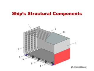
Ship Structural Components
•Download as PPT, PDF•
55 likes•42,425 views

Ship Structural Components For Ship Construction Subject

Recommended
More Related Content
What's hot
What's hot (20)
Similar to Ship Structural Components
Similar to Ship Structural Components (20)
More from Mohammud Hanif Dewan M.Phil.
More from Mohammud Hanif Dewan M.Phil. (20)
Recently uploaded
Recently uploaded (20)
Ship Structural Components
- 2. LongitudinalLongitudinal Structural ComponentsStructural Components Keel - Large center-plane girder - Runs longitudinally along the bottom of the ship • Longitudinals - Girders running parallel to the keel along the bottom - It provides longitudinal strength 2
- 3. Longitudinal Structural Components (cont’d) • Deck Girder - Longitudinal member of the deck frame (deck longitudinal) • Stringer - Girders running along the sides of the ship - Typically smaller than a longitudinal - Provides longitudinal strength ….Primary role of longitudinal members : Resist the longitudinal bending stress due to sagging and hogging 3
- 4. Transverse Structural Components • Floor - Deep frame running from the keel to the turn of the bilge • Frame - A transverse member running from keel to deck - Resists hydrostatic pressure, waves, impact, etc. - Frames may be attached to the floors (Frame would be the part above the floor) • Deck Beams - Transverse member of the deck frame •Primary role of transverse members : to resist the hydrostatic loads 4
- 5. • Plating - Thin pieces closing in the top, bottom and side of structure - Contributes significantly to longitudinal hull strength - Resists the hydrostatic pressure load (or side impact) 5
- 8. The ship’s strength can be increased by: - Adding more members - increasing the size & thickness of plating and structural pieces All this will increase cost, reduce space utilization, and allow less mission equipment to be added Optimization • Longitudinal Framing System • Transverse Framing System • Combination of Framing System 8
- 9. Shell Plating details: 9 (Longitudinal) Rows of plating are called “strakes” Welded horizontal joints between strakes are called seams Welded vertical joints between plates in a given strake are called butts Strakes that do not run the entire ship length (as the hull surface area decreases at the ends) are drop strakes Bilge (“F”) Strake “G” Strake “H” Strake drop “J” Strake Through “K” Strake Sheer Strake Strakes running stem to stern are called through strakes An oversized plate merging a drop & through strake is a stealer plate The strake at the deck edge is the sheer strake and is heavier than typical side shell plating
- 10. Shell & Deck Construction Seam or ‘Edge Laps’ are joints which runs fore and aft, along the longer edges of plates Butts or ‘End Laps’ are joints which run athwartships, or vertically, along the shorter edges of plates. Sheer strakes are the upper strakes (continuous, fore and aft, lines of plates) of shell plating on either side, next to upper deck. 10
- 11. Shell & Deck Construction Welded plating is more liable to crack under hogging and sagging stresses, especially in the region of sheer strake and the bilge. The upper edges of sheer strake should be ground -off smooth, whilst other parts should not be welded to it, if avoidable Any openings in the shell plating must have special arrangements to preserve strength and their corners must be rounded. 11
- 12. Shell & Deck Construction The corners of the openings must be rounded and special arrangement to preserve strength When large openings, such as cargo doors, are cut in the plating, they are usually framed in by a face bar. Web frames are often placed on either side of the opening and insert plates are fitted above and below it, or right around it. 12
- 13. Openings in shell plating must: * have rounded corners * be reinforced to make up for missing material 13 portholes Watertight doors Hatch openings below decks … and on weather deck -- COAMINGS
- 14. Shell & Deck Construction 14
- 15. Transverse Framing System Stiffening the shell plating, prevents buckling and resists distortion of vessel due to racking The frames support ends of deck beams Frames are closely spaced where loading is higher especially at ends of ships Provide transverse strength. 15
- 16. Transverse Framing System • Ships shorter than 300ft and submersibles •Transverse Framing System: - Longitudinals are spaced widely but deep. - Frames are spaced closely and continuously •Transverse members: frame, floor, deck beam, platings •Primary role of transverse members : to resist the hydrostatic loads 16
- 17. Transverse Framing: • Deck Beams tie upper ends of frames • Fewer, deeper & more widely spaced Longitudinals … • Support Inner Bottom & give longitudinal strength 17 Longitudinals supporting Decks are called (Deck) Girders Additional Decks (supported by Beams & Girders) increase Transverse & Longitudinal strength Many, closely-spaced Frames Transverse Bulkheads provide watertight boundaries, contribute significantly to transverse strength, and provide vertical support for Decks
- 18. Transverse Framing: • Advantages • Open, nearly rectangular interior space • Ideal for stowing large, irregular, break-bulk items, or • Vehicles (Ro-Ro’s) • Disadvantages • Vertical support for decks requires more closely spaced transverse bulkheads (hence smaller compartments) or • Pillars (stanchions) or • Longitudinal bulkheads 18 Many, closely-spaced Frames
- 20. Longitudinal Framing System On ship sides, longitudinals extend from one transverse bulkhead to another. Frames supported at intervals by vertical web frames (heavy plate frame) spaced about 4m apart. Provide longitudinal strength The size of the longitudinals ( usually bulb plates) depends on the spacing, span between bulkhead, length of ship and distance from the deck 20
- 21. Longitudinal Framing System • A typical wave length in the ocean is 300 ft. Ships of this length or greater are likely to experience considerable longitudinal bending stress • Ship that are longer than 300ft (long ship) tend to have a greater number of longitudinal members than transverse members Longitudinal Framing System : - Longitudinals spaced frequently but shallower - Frames are spaced widely Primary role of longitudinal members : to resist the longitudinal bending stress due to sagging and hogging 21
- 22. Longitudinal Framing: • Few & widely spaced • Smaller, closely- spaced Longitud-nals support shell plating • Side shell longitudinals call stringers 22 Deep (Web) Transverse Frames Inner Bottom gives additional longitudinal & transverse strength Girders in high-stress areas: Double bottom spaces and … Under main deck
- 23. Longitudinal Framing: • Advantages • Widely spaced transverse bulkheads allow for large (i.e., long) continuous cargo spaces (“tanks”) • Ideal for stowing liquids (reduced free surface effects) • Disadvantages • No large, open interior spaces • Difficult to load or unload break-bulk items • Difficult to stow large, irregular shaped items 23 Deep (Web) Transverse Frames
- 25. Longitudinally framed hull (tanker) The longitudinal framing is much better able to resist buckling when the hull is hogging Source: www.marineengineering.org.uk 25
- 29. Longitudinal framing (Dry Cargo) Source: www.marineengineering.org.uk 29
- 30. Source: 30
- 33. 33
- 34. Combination Framing System Introduced to overcome the disadvantage of longitudinal system in dry cargo ships. The longitudinal frames are retained at the bottom and under the strength deck to give longitudinal strength. Transverse frames are fitted on ship’s sides where longitudinal stresses are smaller Plate floors and heavy transverse beams are fitted at intervals to give transverse strength and support the longitudinals 34
- 35. Framing Systems:Framing Systems: • Typically, most ships have some combination of transverse & longitudinal framing 35 TTTTTTTTTTTTTTTTT CL CL SECTION VIEW PLAN VIEW Typical Transverse Frames Web Frame L L L L L L L L L L FLOOR UPPER TWEEN DECK LOWER TWEEN DECK (LOWER) HOLD Bulkhead STIFFENERS Stringer
- 36. Combined Framing System • Combination of longitudinal and transverse framing system • Typical combination : - Longitudinals and stringers with shallow frame - Deep frame every 3rd or 4th frame Optimization of the structural arrangement for the expected loading to minimize the cost 36
- 38. Double Bottom Tank: An inner bottom (or tank top) may be provided at a minimum height above the bottom shell, and maintained watertight to the bilges. This provides a considerable margin of safety, since in the event of bottom shell damage only the double bottom space may be flooded. The space is not wasted but utilised to carry oil fuel and fresh water required for the ship, as well as providing ballast capacity. It may be deeper to give the required capacities of oil fuel, fresh water, and water ballast to be carried in the bottom. Water ballast bottom tanks are commonly provided right forward and aft for trimming purposes and if necessary the depth of the double bottom may be increased in these regions. In way of the machinery spaces the double bottom depth is also increased to provide appreciable capacities of lubricating oil and fuel oil. The increase in height of the inner bottom is always by a gradual taper in the longitudinal direction, no sudden discontinuities in the structure being tolerated.
- 39. Double bottoms may be framed longitudinally or transversely , but where the ship’s length exceeds 120m it is considered desirable to adopt longitudinal framing. The explanation of this is that on longer ship tests and experience have shown that there is a tendency for the inner bottom and bottom shell to buckle if welded transverse framing is adopted. This buckling occurs as a result of the longitudinal bending of the hull, and may be avoided by having the plating longitudinally stiffened
- 40. Source:
- 42. Transversally
- 43. Double Bottom details:Double Bottom details: 43 Rider Plate Inner Bottom (Tank Top) Air- hole Margin Plate Center Vertical Keel Keel Plate Outer Bottom Lightening hole Limber hole Longitudinal Bilge Frame “SOLID” FLOOR Reverse Frame “OPEN” FLOOR Frame Longitudinal Strut Bilge well
- 44. Shell Plating details:Shell Plating details: 44 Keel Strake Garboard Strake (“A” strake) “B” Strake “C” Strake “D” Strake “E” Strake “G” Strake “F” Strake (Bilge Strake) (Longitudinal) Rows of plating are called “strakes” The Keel Plates form the “Keel strake” The strakes outboard (P&S) of the Keel are the “A” Strakes or “Garboard Strakes” Strakes are consecutively lettered moving outboard and up the side shell
- 45. Double Bottoms • Resists: - Upward pressure - bending stresses - bottom damage by grounding and underwater shock • The double bottom provides a space for storing: - fuel oil - ballast water & fresh water • Smooth inner bottom which make it easier to arrange cargo & equipment and clean the cargo hold Two watertight bottoms with a void space 45
- 46. Deck Plating Deck plating is supported by pillars which ‘tie in’ the deck and connect with the bottom structure. The pillars also transmit deck loads to the bottom structure, where there are distributed into the floors 46
- 47. Discontinuities- Hatchways Coamings height on freeboard deck : 600 mm and abaft ¼ of length on exposed superstructure deck from stem : 450 mm Squared corners not allowed. Openings may be elliptical or parabolic, or the corners may be rounded-off The radius at the corners must be at least 1/24 th of breadth of opening, but not less than 300mm Doubling plates not allowed in welded decks, so insert plates must be fitted at the hatch corners. 47
- 48. Hatch Corners 48
- 49. Openings in the shell – Suction and Discharge Fittings If discharges comes from below freeboard deck, they must be fitted with non-return valves except for discharges from manned E/R A scupper passes through the shell plating at a distance of more than 450 mm below freeboard deck or less than 600 mm above the load waterline, it must have an automatic non-return valve fitted at the shell A scupper from deck below freeboard deck must lead down to the bilges or fitted with SDNR valve 49