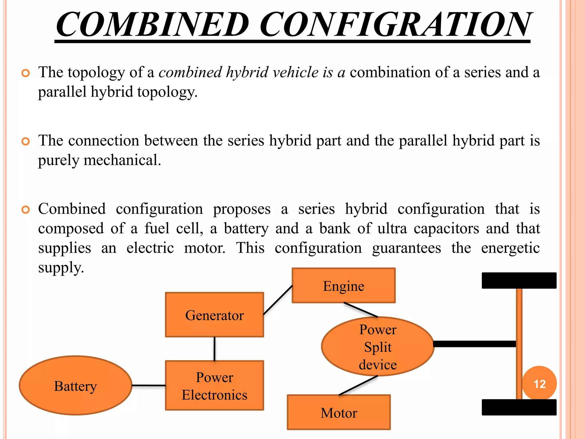
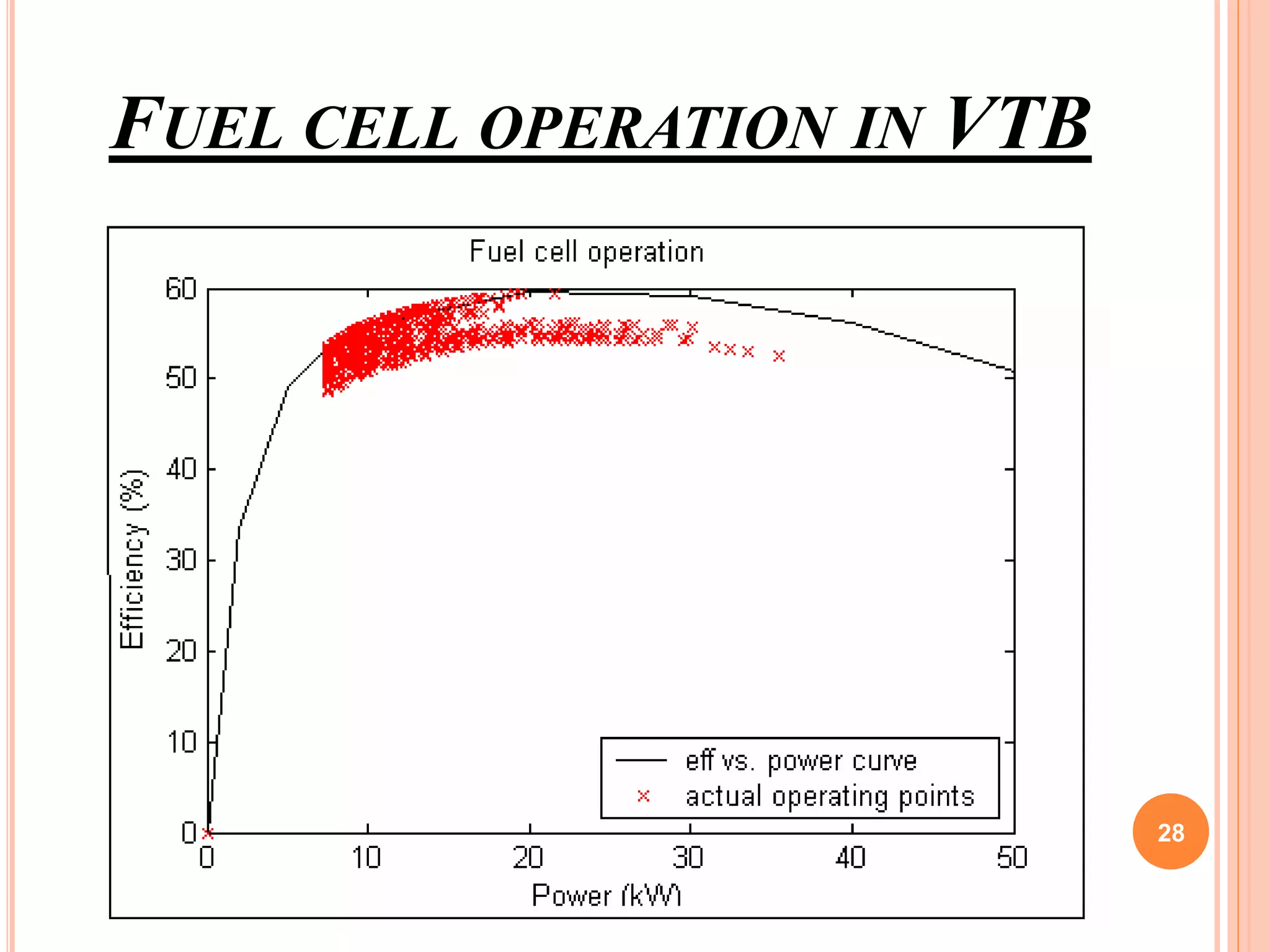
A HYBRID VEHICLE CONFIGURATION
WITH ZERO EMISSION
Guided By, Submitted By,
Kavithamol S Kichu Georgy Joy
Asst. Professor S7 Mechanical
B J G I 11436034
Kollam BJGI
Kollam
1
CONTENTS
•Introduction
•Description of Components
•Simulations
•General scheme
•Conclusions
•References
2
INTRODUCTION
 Zero Emission Vehicle
 Traditional fuels
 Transport Sector.
 “Hybrid” concept
3
HYBRID ELECTRIC VEHICLE
 Any vehicle that combines 2 or more sources of power.
 Relies not only on batteries but also on an internal combustion
engine which drives a generator to provide electricity and may
also drive a wheel.
 Alternative power unit
 Supply the power required by the vehicle,
 Recharge the batteries
 Power accessories like the air conditioner and heater
4
HYBRID STRUCTURE
Three types of hybrid vehicle configurations
 Series Hybrid
 Parallel Hybrid
 Combined Hybrid
5
SERIES HYBRID
 The total energy on board results from the combination of two or more
power sources.
 The internal combustion engine (ICE) connects to a generator (GEN) to
produce electrical power. This electric power is stored in a battery (BAT).
 The electrical motor (EM) works with AC current, so an inverter (INV) is
necessary to turn the DC current to AC current.
 The electric motor supplies the traction power to wheels across a mechanical
differential gear. Therefore, the traction is obtained from an only central
electric motor.
6
SERIES HYBRID
 Similar to an electric vehicle with an on-board generator .
 The vehicle runs on battery power like a pure electric vehicle until the
batteries reach a predetermined discharged level.
 At that point the APU turns on and begins recharging the battery.
 The APU operates until the batteries are charged to a predetermined
level.
 APU never directly powers the vehicle.
 The length of time the APU is on depends on the size of the batteries and
the APU itself.
7
SERIES HYBRID (BLOCK DIAGRAM)
8
Figure 1
PARALLEL HYBRID
 This topology is a combination of traction systems: an electric motor and an
internal combustion engine work jointly.
 The power distribution is just mechanical. The internal combustion engine
connects directly to a gear box (GB) to produce mechanical power.
 The energy stored by the battery converts to AC by an inverter. Then the
electric motor transforms the electric power to mechanical power.
 There are 3 working ways for this topology.
 The gear box can receive power from two sources (internal combustion engine and
battery)
 Someone of the sources is off
 The internal combustion engine drives only the electric machine to charge the
battery.
9
PARALLEL HYBRID
 When the APU is off, the parallel hybrid runs like an electric vehicle
 When the APU is on, the controller divides energy between the drive train
(propulsion) and the batteries (energy storage).
 Under acceleration, more power is allocated to the drive train than to the
batteries.
 During periods of idle or low speeds, more power goes to the batteries
than the drive train.
 The batteries also provide additional power to the drive train when the
APU is not producing enough and also to power auxiliary systems such as
the air conditioner and heater. 10
PARALLEL HYBRID (BLOCK DIAGRAM)
11
Figure 2
COMBINED CONFIGRATION
 The topology of a combined hybrid vehicle is a combination of a series and a
parallel hybrid topology.
 The connection between the series hybrid part and the parallel hybrid part is
purely mechanical.
 Combined configuration proposes a series hybrid configuration that is
composed of a fuel cell, a battery and a bank of ultra capacitors and that
supplies an electric motor. This configuration guarantees the energetic
supply.
Battery
Power
Electronics
Generator
Power
Split
device
Engine
Motor
12
COMBINED CONFIGURATION
 The control strategies developed in series hybrid topologies with fuel cell do
not satisfy simultaneously the power demand and the optimum energetic
efficiency of the electrical components.
 Fuzzy control policies based on machine learning of models by neuro-fuzzy
techniques and on non-lineal control strategies.
 The current fuzzy control applications are related to configurations that
combine an internal combustion engine with an electric motor
13
DESCRIPTION OF COMPONENTS
 The system proposed in this work belongs to a series
hybrid topology. The energy sources are
 A fuel cell,
 A battery and
 A bank of ultra capacitors.
14
1. FUEL CELL
 It is the basic element of energetic supply of the vehicle.
 Aspects that determine the election of the fuel cell:
 The electrolyte that is used in the chemical reaction
 The used fuel
 The temperature of operation
 The maximum efficiency
 The main restriction in the fuel cell operation can be
observed from the curve of maximum efficiency. 15
EFFICIENCY CURVE
16
2 . BATTERY
 Purpose of using the battery is to reduce the difference
between the power supplied by the fuel cell and the power
required by the engine.
 It is not possible to demand high power levels in short time
periods because it supposes an increase of the losses and the
operating temperature, as well as a decrease of the estimated
average life time.
17
MAXIMUM BATTERY POWER
18
3. ULTRACAPACITOR
 Ultracapacitor cover, in short time periods, the peaks of maximum power
demand. Therefore, it is essential to include this device.
 The fuel cell together with the battery can not provide all the power
required by the other engine.
 The most difference between this device and a conventional capacitor is the
material of construction: the ultra capacitor dielectric is an electrolyte.
 Due to its high energetic density, the ultracapacitor can store efficiently the
electric energy liberated during the regenerative braking, once the battery
has been charged.
19
MAXIMUM ULTRA CAPACITOR POWER
20
SIMULATION
 National Renewable Energy Laboratory (NREL) has developed a vehicles
simulator called ADVISOR (Advanced Vehicle Simulator), which is available
since 2008
 In this simulator, we can find an electric hybrid vehicle model with a fuel cell.
The additional energy sources are only a battery.
 The simulation tests were carried out with a 1380 kg vehicle and a driving cycle
named CYC_CLEVELAND, that is similar to a road cycle.
 Figure shows that there are differences between the demanded and the reached
velocity, whose maximum values are around 30 km/h. This fact is caused by the
energetic insufficiency presented in the vehicle configuration.
21
22
SIMULATION
 The University of South California is also developing a simulation tool,
Virtual Test Bed (VTB), that allows to create virtual prototypes with
different power sources and to connect different blocks easily.
 A hybrid model with a fuel cell, a battery and a bank of ultracapacitors is
available in this tool.
 Graph shows the tests carried out with this model. The same parameters
than the previous simulation were used. The results indicate that the
difference between the demanded and the reached velocity is much
smaller.
23
24
SIMULATION
 In the two cases, the control strategy consists on comparing the power required
in the DC bus with the power available in each source. When the power
required is bigger than the power available in the fuel cell, the battery supplies
the difference.
 It was said that the bank of ultracapacitors offers high power levels in short
time intervals.
 The algorithm that is often used is based on comparing the demanded power
and the one that can provide each source, taking into account the fuel cell
operation state and the battery charge state.
 Following graph, shows how the fuel cell does not follow its curve of
maximum efficiency. This result was obtained by means of ADVISOR using
the series hybrid configuration with fuel cell and battery, without
ultracapacitors, and the same parameters than the other simulations.
25
FUEL CELL OPERATION
26
SIMULATION
 On the other hand, it has been seen that the power provision is
guaranteed with the three power sources. The next feature of the
proposed topology that has to be verified is the energetic efficiency.
 Following graph, obtained with VTB and the same parameters than
previous simulations, shows how the operation points do not follow
the maximum efficiency curve. Therefore, a new control strategy
would be advisable
27
FUEL CELL OPERATION IN VTB
28
GENERAL SCHEME
 Energy Sources
 Control System
 Electric motor
 Programmable load
 Hydrogen Storage
29
ZERO EMISSION VEHICLE WORKING
30
CONCLUSION
 Hybrid vehicle composed of a fuel cell and a battery is not enough to
guarantee the energy supply.
 Configuration composed of the three energy sources (the fuel cell, battery
and bank of ultra capacitors) reduces the difference between the demanded
and the supplied power.
 Fuel cell does not work in the maximum energy efficiency range, and so a
new control strategy is justified.
 New control strategy is being developed.
 Fuzzy control policies are being developed.
31
REFERENCES
 Andújar, J. M., J. M. Bravo and A. Peregrín., “Stability analysis and synthesis of
multivariable fuzzy systems using interval arithmetic”, Fuzzy Sets and
Systems,2004. http://dx.doi.org/10.1016/j.fss.2004.01.008.
 Dougal R. A., Liu S., Gas L., Blackwelder M., “Virtual Test Bed for Advanced
Power Sources",. Journal of Power and Sources,Vol.110, pp.285-295, 2002.
 Markel T., Brooker A., Hendricks T., Jhonson V., Kelly K., Kamer B., O’Keefe
M., Sprik S., Wipke K., “Advisor: a Systems Analysis Tool for Advanced Vehicle
Modeling”, Journal of Power and Sources, Vol.110, pp.255-266. 2002.
32
THANK YOU
[END OF PRESENTATION]
33

A hybrid vehicle configuration with zero emission

  • 1.
    A HYBRID VEHICLECONFIGURATION WITH ZERO EMISSION Guided By, Submitted By, Kavithamol S Kichu Georgy Joy Asst. Professor S7 Mechanical B J G I 11436034 Kollam BJGI Kollam 1
  • 2.
  • 3.
    INTRODUCTION  Zero EmissionVehicle  Traditional fuels  Transport Sector.  “Hybrid” concept 3
  • 4.
    HYBRID ELECTRIC VEHICLE Any vehicle that combines 2 or more sources of power.  Relies not only on batteries but also on an internal combustion engine which drives a generator to provide electricity and may also drive a wheel.  Alternative power unit  Supply the power required by the vehicle,  Recharge the batteries  Power accessories like the air conditioner and heater 4
  • 5.
    HYBRID STRUCTURE Three typesof hybrid vehicle configurations  Series Hybrid  Parallel Hybrid  Combined Hybrid 5
  • 6.
    SERIES HYBRID  Thetotal energy on board results from the combination of two or more power sources.  The internal combustion engine (ICE) connects to a generator (GEN) to produce electrical power. This electric power is stored in a battery (BAT).  The electrical motor (EM) works with AC current, so an inverter (INV) is necessary to turn the DC current to AC current.  The electric motor supplies the traction power to wheels across a mechanical differential gear. Therefore, the traction is obtained from an only central electric motor. 6
  • 7.
    SERIES HYBRID  Similarto an electric vehicle with an on-board generator .  The vehicle runs on battery power like a pure electric vehicle until the batteries reach a predetermined discharged level.  At that point the APU turns on and begins recharging the battery.  The APU operates until the batteries are charged to a predetermined level.  APU never directly powers the vehicle.  The length of time the APU is on depends on the size of the batteries and the APU itself. 7
  • 8.
    SERIES HYBRID (BLOCKDIAGRAM) 8 Figure 1
  • 9.
    PARALLEL HYBRID  Thistopology is a combination of traction systems: an electric motor and an internal combustion engine work jointly.  The power distribution is just mechanical. The internal combustion engine connects directly to a gear box (GB) to produce mechanical power.  The energy stored by the battery converts to AC by an inverter. Then the electric motor transforms the electric power to mechanical power.  There are 3 working ways for this topology.  The gear box can receive power from two sources (internal combustion engine and battery)  Someone of the sources is off  The internal combustion engine drives only the electric machine to charge the battery. 9
  • 10.
    PARALLEL HYBRID  Whenthe APU is off, the parallel hybrid runs like an electric vehicle  When the APU is on, the controller divides energy between the drive train (propulsion) and the batteries (energy storage).  Under acceleration, more power is allocated to the drive train than to the batteries.  During periods of idle or low speeds, more power goes to the batteries than the drive train.  The batteries also provide additional power to the drive train when the APU is not producing enough and also to power auxiliary systems such as the air conditioner and heater. 10
  • 11.
    PARALLEL HYBRID (BLOCKDIAGRAM) 11 Figure 2
  • 12.
    COMBINED CONFIGRATION  Thetopology of a combined hybrid vehicle is a combination of a series and a parallel hybrid topology.  The connection between the series hybrid part and the parallel hybrid part is purely mechanical.  Combined configuration proposes a series hybrid configuration that is composed of a fuel cell, a battery and a bank of ultra capacitors and that supplies an electric motor. This configuration guarantees the energetic supply. Battery Power Electronics Generator Power Split device Engine Motor 12
  • 13.
    COMBINED CONFIGURATION  Thecontrol strategies developed in series hybrid topologies with fuel cell do not satisfy simultaneously the power demand and the optimum energetic efficiency of the electrical components.  Fuzzy control policies based on machine learning of models by neuro-fuzzy techniques and on non-lineal control strategies.  The current fuzzy control applications are related to configurations that combine an internal combustion engine with an electric motor 13
  • 14.
    DESCRIPTION OF COMPONENTS The system proposed in this work belongs to a series hybrid topology. The energy sources are  A fuel cell,  A battery and  A bank of ultra capacitors. 14
  • 15.
    1. FUEL CELL It is the basic element of energetic supply of the vehicle.  Aspects that determine the election of the fuel cell:  The electrolyte that is used in the chemical reaction  The used fuel  The temperature of operation  The maximum efficiency  The main restriction in the fuel cell operation can be observed from the curve of maximum efficiency. 15
  • 16.
  • 17.
    2 . BATTERY Purpose of using the battery is to reduce the difference between the power supplied by the fuel cell and the power required by the engine.  It is not possible to demand high power levels in short time periods because it supposes an increase of the losses and the operating temperature, as well as a decrease of the estimated average life time. 17
  • 18.
  • 19.
    3. ULTRACAPACITOR  Ultracapacitorcover, in short time periods, the peaks of maximum power demand. Therefore, it is essential to include this device.  The fuel cell together with the battery can not provide all the power required by the other engine.  The most difference between this device and a conventional capacitor is the material of construction: the ultra capacitor dielectric is an electrolyte.  Due to its high energetic density, the ultracapacitor can store efficiently the electric energy liberated during the regenerative braking, once the battery has been charged. 19
  • 20.
  • 21.
    SIMULATION  National RenewableEnergy Laboratory (NREL) has developed a vehicles simulator called ADVISOR (Advanced Vehicle Simulator), which is available since 2008  In this simulator, we can find an electric hybrid vehicle model with a fuel cell. The additional energy sources are only a battery.  The simulation tests were carried out with a 1380 kg vehicle and a driving cycle named CYC_CLEVELAND, that is similar to a road cycle.  Figure shows that there are differences between the demanded and the reached velocity, whose maximum values are around 30 km/h. This fact is caused by the energetic insufficiency presented in the vehicle configuration. 21
  • 22.
  • 23.
    SIMULATION  The Universityof South California is also developing a simulation tool, Virtual Test Bed (VTB), that allows to create virtual prototypes with different power sources and to connect different blocks easily.  A hybrid model with a fuel cell, a battery and a bank of ultracapacitors is available in this tool.  Graph shows the tests carried out with this model. The same parameters than the previous simulation were used. The results indicate that the difference between the demanded and the reached velocity is much smaller. 23
  • 24.
  • 25.
    SIMULATION  In thetwo cases, the control strategy consists on comparing the power required in the DC bus with the power available in each source. When the power required is bigger than the power available in the fuel cell, the battery supplies the difference.  It was said that the bank of ultracapacitors offers high power levels in short time intervals.  The algorithm that is often used is based on comparing the demanded power and the one that can provide each source, taking into account the fuel cell operation state and the battery charge state.  Following graph, shows how the fuel cell does not follow its curve of maximum efficiency. This result was obtained by means of ADVISOR using the series hybrid configuration with fuel cell and battery, without ultracapacitors, and the same parameters than the other simulations. 25
  • 26.
  • 27.
    SIMULATION  On theother hand, it has been seen that the power provision is guaranteed with the three power sources. The next feature of the proposed topology that has to be verified is the energetic efficiency.  Following graph, obtained with VTB and the same parameters than previous simulations, shows how the operation points do not follow the maximum efficiency curve. Therefore, a new control strategy would be advisable 27
  • 28.
  • 29.
    GENERAL SCHEME  EnergySources  Control System  Electric motor  Programmable load  Hydrogen Storage 29
  • 30.
  • 31.
    CONCLUSION  Hybrid vehiclecomposed of a fuel cell and a battery is not enough to guarantee the energy supply.  Configuration composed of the three energy sources (the fuel cell, battery and bank of ultra capacitors) reduces the difference between the demanded and the supplied power.  Fuel cell does not work in the maximum energy efficiency range, and so a new control strategy is justified.  New control strategy is being developed.  Fuzzy control policies are being developed. 31
  • 32.
    REFERENCES  Andújar, J.M., J. M. Bravo and A. Peregrín., “Stability analysis and synthesis of multivariable fuzzy systems using interval arithmetic”, Fuzzy Sets and Systems,2004. http://dx.doi.org/10.1016/j.fss.2004.01.008.  Dougal R. A., Liu S., Gas L., Blackwelder M., “Virtual Test Bed for Advanced Power Sources",. Journal of Power and Sources,Vol.110, pp.285-295, 2002.  Markel T., Brooker A., Hendricks T., Jhonson V., Kelly K., Kamer B., O’Keefe M., Sprik S., Wipke K., “Advisor: a Systems Analysis Tool for Advanced Vehicle Modeling”, Journal of Power and Sources, Vol.110, pp.255-266. 2002. 32
  • 33.
    THANK YOU [END OFPRESENTATION] 33