
Recommended
More Related Content
What's hot
What's hot (20)
Similar to Vlsi model question paper 1
Similar to Vlsi model question paper 1 (20)
Recently uploaded
Recently uploaded (20)
Vlsi model question paper 1
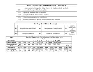
- 1. Course Outcomes – 19EC404 ELECTRONICS CIRCUITS II After successful Completion of the Course, the Students should be able to CO1 Analyze the four types of feedback amplifiers CO2 Design and simulate LC and RC oscillators CO3 Verify the bandwidth of various tuned amplifiers.. CO4 Analyze wave shaping circuits, multivibrators CO5 Compare performance of blocking oscillators and time base generators Knowledge Level (Blooms Taxonomy) K1 Remembering (Knowledge) K2 Understanding (Comprehension) K3 Applying (Application of Knowledge) K4 Analysing (Analysis) K5 Evaluating (Evaluation) K6 Creating (Synthesis) Part Question Mapping with Course Outcomes and Knowledge Level Part -A Question No. 1 2 3 4 5 6 7 8 9 10 Course Outcome CO1 CO1 CO2 CO2 CO3 CO3 CO4 CO4 CO5 CO5 Knowledge Level K3 K3 K4 K2 K2 K3 K3 K3 K3 K3 Part Part –B Part - C Question No. 11 (a) 11(b) 12(a) 12(b) 13(a) 13(b) 14(a) 14(b) 15(a) 15(b) 16 (a) 16(b) Course Outcome CO1 CO1 CO2 CO2 CO3 CO3 CO4 CO4 CO5 CO5 CO5 CO5 Knowledge Level K4 K3 K3 K4 K4 K3 K4 K4 K2 K4 K2 K4
- 2. Saveetha Nagar, Thandalam, Chennai – 602105 MODEL EXAM #2 – June 2021 Degree : B.E / Branch : ECE / Semester : IV Sem Date : 08.06.2021/Session :FN/ Duration : 3 hours 19EC404/ ELECTRONICS CIRCUITS II Time : 9.a.m to 12 p.m Total Marks: 100 PART – A 10X2 = 20 marks 1. The open loop gain of an amplifier is 50 and its bandwidth is 20 kHz. When a negative feedback is applied, the bandwidth is increased to 25kHz.What will be the required feedback ratio? 2. How the stability condition is determined for a feedback amplifier using Nyquist criteria? 3. The loop gain of a feedback amplifier circuit is Aβ. What are the conditions that has to be satisfied for the circuit to function as an oscillator? 4. For an oscillator which has a tuned circuit at the collector, determine the frequency of oscillation with the given values of L as 100mH and C as 15pF. 5. Mention the differences between the single tuned and double tuned amplifier with respect to the bandwidth and tank circuit. 6. A tuned Circuit has a resonant frequency of 1500kHz and a BW of 10kHZ. What is the value of its Q factor? 7. A 20 KHz, 75% duty cycle square wave is used to trigger a monostable multi vibrator continuously with a triggered pulse duration of 5 µs. What will be the duty cycle of the waveform at the output of the monostable multi vibrator? 8. In an Astable multivibrator circuit R1 = R2 = 10K, C1 = C2= 0.01µF and RL1 = RL2 = 1K . Find a)Frequency of oscillation of circuit b)minimum value of the transistor β 9. For the UJT Oscillator circuit R= 10K, η = 0.75. if the required oscillator frequency is 1KHz. Find the value of C 10. Find the sweep frequency of UJT relaxation Oscillator with the given specifications : R=75KΩ, C=0.5µF and η = 0.62 PART – B 13X5 = 65 marks 11(a) Draw the circuit diagram of a shunt-series feedback amplifier. What are the other names of the above feedback amplifier and why it is called so? Explain. What is the sampled signal and mixing signal in the above amplifier? Derive the expressions for the gain, input and output resistances of the above amplifier (or)
- 3. 11(b) In a BJT amplifier, part of the output voltage is connected in shunt with input. Examine the effect of this feedback on input resistance and output resistance of the amplifier? Explain the same, with necessary circuit, equivalent circuit and obtain the expressions for gain of the amplifier with and without feedback, feedback factor, input and output resistances. 12(a) With neat diagram, explain the circuit which has three capacitors and one inductor in the feedback network. Also derive the frequency of oscillation for the above circuit. (or) 12(b) Identify the circuit in which the feedback network acts as a notch filter. What is the other name of the network and explain why the network is called by that name and give the frequency of oscillation of the above oscillator. Explain in detail about the oscillator with neat circuit. Determine the frequency of oscillation if the value of R=200kΩ and C=300pF. 13(a) Derive the expression for the Q factor of an Inductor and Capacitor. A tank circuit has a capacitor of 200pF and an inductor of 150µH. The resistance of the inductor is 10Ω. Determine the (a) resonant frequency, (b) impedance at resonance, (c) Q-factor and (d) Bandwidth (or) 13(b) Why tuned amplifiers are preferred in Radio Receivers? A tuned circuit contains an inductance of 1mH .Find out the range of tuning capacitor value if the resonant frequency ranges from 540kHz to 1650KHZ. Discuss the frequency response of a stagger tuned amplifier. 14(a) Which multivibrator is called as free running Multivibrator? Why it is called so? Explain the above multivibrator with neat circuit diagram. Determine the value of capacitors to be used in an Astable multi vibrator to provide a train of pulse 2 µ s wide at a repetition rate of 75 kHz if R1= R2=10K (or) 14(b) A 10V step signal is switched onto a circuit consisting of 50kΩ series resistor and a 500 pF shunt capacitor. Identify the circuit. Draw the circuit diagram and explain. Calculate (a) the rise time of the capacitor voltage, (b) the time for the capacitor to charge to 63.2% of its maximum voltage, and (c) the time for the capacitor to be completely charged. 15 (a) Derive the frequency of oscillation of a UJT Relaxation Oscillator. A UJT with 𝛈 = 0.62 is used as a relaxation Oscillator circuit with R=5KΩ and C=0.05µF. (a) Determine the period and frequency Oscillation. (c) If C is increased by a factor of 10, how the value of R changes, if the frequency is to be 50Hz (or) 15 (b) Consider a regenerative circuit in which the output of an active device is fed back to the input using pulse transformer. The circuit operates on application of triggering pulse. A timing Resistor is connected across the base of the circuit which controls the gate width. Identify the circuit. Draw the circuit diagram and explain the base and collector current waveforms PART – C 15X1 = 15 marks 16 (a) Explain RC coupled push pull Astable Blocking Oscillator with emitter timing in detail. Derive the expression for its pulse width. (or)
- 4. 16 (b) Mention the applications of current time base generator. Explain current time base circuit with relevant waveforms