
Recommended
More Related Content
What's hot
What's hot (20)
Similar to Tensile test
Similar to Tensile test (20)
More from Vijay Kumar Jadon
More from Vijay Kumar Jadon (16)
Recently uploaded
Recently uploaded (20)
Tensile test
- 1. Tensile Test V K Jadon V K Jadon, Professor, Mechanical Engineering
- 2. V K Jadon, Professor, Mechanical Engineering Tensile Test Elongation(%) and Reduction in Area(%) Resilience and Toughness Material Properties
- 3. V K Jadon, Professor, Mechanical Engineering Maximum induced stress at any point in a loaded machine member <= Design Stress Design Stress = 𝑆𝑡𝑟𝑒𝑛𝑔𝑡ℎ 𝐹𝑎𝑐𝑡𝑜𝑟 𝑜𝑓 𝑆𝑎𝑓𝑒𝑡𝑦 How many design equations are needed for one component to fix one dimension of a member? ? Design equation for Strength (Static Load) ?
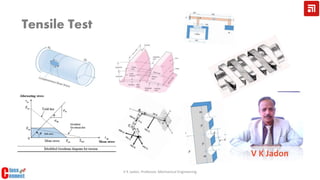
- 4. Engineering stress or stress 𝜎 = 𝐹 𝐴 𝑜 Engineering strain or strain 𝜀 = 𝑙 𝑓−𝑙 𝑜 𝑙 𝑜 Tensile Test The cross-section of specimen can be circular, square and rectangular (IS 1608-2005) 𝑙0 = 5 × 𝐷 for circular section 𝑙0 = 5.65√𝐴0 for non-circular section Tensile Test is conducted to know mechanical strength, elastic constant and ductility of material. 𝑑 𝑜 = 6 𝑚𝑚 𝑙 𝑜 = 30 𝑚𝑚 Representative Curve for Mild Steel (Not as per data) V K Jadon, Professor, Mechanical Engineering Load (kN) Elongation (mm) 0.25 0.01 0.50 0.05 0.91 0.10 1.15 0.30 1.57 0.50 3.32 0.80 8.36 1.5
- 5. 𝜎 = 𝐹 𝐴 𝑜 𝜀 = 𝑙 𝑓−𝑙 𝑜 𝑙 𝑜 Tensile Test : Material Properties Load (kN) Elongation (mm) 0.25 0.0013 0.50 0.0030 0.91 0.0051 1.15 0.0063 1.57 0.0085 3.32 0.0180 8.36 0.0750 𝑑 𝑜 = 6 𝑚𝑚; 𝑙 𝑜 = 30 𝑚𝑚; 𝐴 𝑜 = 26.27 𝑚𝑚2 Stress (MPa) Strain 9.51 0.000045 19.03 0.00010 34.46 0.00017 43.78 0.00021 59.76 0.00028 126.38 0.00060 318.23 0.0025 𝑆 𝑦𝑡 = 190 − 250 𝑀𝑃𝑎 𝑆 𝑢𝑡 = 350 − 470 𝑀𝑃𝑎 𝐸 = 210000 𝑀𝑃𝑎 E = (34.46 − 19.03) (0.00017 − 0.0001) E = 210428 𝑀𝑃𝑎 E = 210.4 𝐺𝑃𝑎 𝐸 = 210 𝐺𝑃𝑎 Representative values for Steel 𝑆(𝑦/𝑢)𝑐 = (1.2 − 1.7)𝑆(𝑦/𝑢)𝑡 𝑆(𝑦/𝑢)𝑠 = 0.5𝑆(𝑦/𝑢)𝑡 𝐺 = 80 𝐺𝑃𝑎 𝜈 = 0.29 𝜈 = − 𝑙𝑎𝑡𝑒𝑟𝑎𝑙 𝑠𝑡𝑟𝑎𝑖𝑛 𝑙𝑜𝑛𝑔𝑖𝑡𝑢𝑑𝑖𝑛𝑎𝑙 𝑠𝑡𝑟𝑎𝑖𝑛 Representative Curve for Mild Steel (Not as per data) V K Jadon, Professor, Mechanical Engineering or 0.577𝑆(𝑦/𝑢)𝑡
- 6. Load (kN) Elongation (mm) 0.25 0.0013 0.50 0.0030 0.91 0.0051 1.15 0.0063 1.57 0.0085 3.32 0.0180 8.36 0.0750 𝑑 𝑜 = 6 𝑚𝑚; 𝑙 𝑜 = 30 𝑚𝑚; 𝐴 𝑜 = 26.27 𝑚𝑚2 Stress (MPa) Longitudinal Strain 9.51 0.000045 19.03 0.00010 34.46 0.00017 43.78 0.00021 59.76 0.00028 126.38 0.00060 318.23 0.0025 𝜈 = 0.29 𝜈 = − 𝑙𝑎𝑡𝑒𝑟𝑎𝑙 𝑠𝑡𝑟𝑎𝑖𝑛 𝑙𝑜𝑛𝑔𝑖𝑡𝑢𝑑𝑖𝑛𝑎𝑙 𝑠𝑡𝑟𝑎𝑖𝑛 Lateral Strain Reduction in Diameter (mm) −1.35 × 10⁻⁵ 8.1 × 10⁻⁵ −2.90 × 10⁻⁵ 1.74 × 10⁻⁴ −4.93 × 10⁻⁵ 2.96 × 10⁻⁴ −6.09 × 10⁻⁵ 3.65 × 10⁻⁴ −8.12 × 10⁻⁵ 4.875 × 10⁻⁴ −17.4 × 10⁻⁴ 1.04 × 10⁻³ −72.5 × 10⁻⁴ 4.35 × 10⁻³ % Elongation % reduction in Area 0.00433 0.00261 0.01 0.0058 0.017 0.00986 0.021 0.01218 0.02833 0.016239 0.06 0.034797 0.25 0.144947 % 𝑟𝑒𝑑𝑢𝑐𝑡𝑖𝑜𝑛 𝑖𝑛 𝑎𝑟𝑒𝑎, 𝑟 = 𝐴 𝑜 − 𝐴 𝑓 𝐴 𝑜 × 100 𝑅𝑒𝑑𝑢𝑐𝑡𝑖𝑜𝑛 𝑖𝑛 𝑑𝑖𝑎 = −𝐿𝑎𝑡𝑒𝑟𝑎𝑙 𝑆𝑡𝑟𝑎𝑖𝑛 × 𝑑0 % 𝑒𝑙𝑜𝑛𝑔𝑎𝑡𝑖𝑜𝑛 = 𝑙 𝑜 − 𝑙 𝑓 𝑙 𝑜 × 100 A material is accepted as ductile if it shows more than 5 percent elongation at fracture. In general, the tendency of a material to be brittle increases with decrease in temperature; increases with rate of loading; and change in state of stress from uniaxial to triaxial tension. Ductility is the most desirable property for the operations like bending, drawing, forming etc. The ductility and brittleness of a material may also be affected due to manufacturing process e.g. the casting of a material is less ductile than the cold/hot working of the same material. Tensile Test : Material Properties V K Jadon, Professor, Mechanical Engineering
- 7. Shear, Bulk, Resilience and Toughness Modulus Shear Modulus (G) is defined as the ratio of shear stress (τ) to shear strain (ϒ) within elastic range and it represents the resistance offered by a material to geometric distortion. This is also called as Modulus of Rigidity 𝐺 = 𝜏 𝛾 This is related to Modulus of Elasticity 𝐺 = 𝐸 2(1+𝜈) Bulk Modulus (K) is a measure of the elastic volume change in a material and is defined as 𝐾 = 𝐻𝑦𝑑𝑎𝑢𝑠𝑡𝑎𝑡𝑖𝑐 𝑆𝑡𝑟𝑒𝑠𝑠 𝑉𝑜𝑙𝑢𝑚𝑒𝑡𝑟𝑖𝑐 𝑆𝑡𝑟𝑎𝑖𝑛 This is related to Modulus of Elasticity 𝐾 = 𝐸 3(1−2𝜈) Reciprocal of the bulk modulus is called compressibility. Resilience When the material undergoes elastic deforma tion, positive work is done on the material WD=product of average load and total change in length This ability of a material to absorb energy when deformed elastically and release the energy when unloaded is known as resilience. Stress Strain Modulus of Resilience (MR) is the area under the stress-strain curve till elastic limit. 𝑀𝑅 = 1 2 (𝑆 𝑦𝑡)(𝜀) 𝑀𝑅 = 1 2 𝑆 𝑦𝑡 2 𝐸 Modulus of Toughness (MT) is the area under the stress-strain curve till fracture. Toughness is a measure of the ability to absorb energy in plastic range i.e. the ability of a material to withstand occasional stress above yield strength without failure. 𝑀𝑇𝑑𝑢𝑐𝑡𝑖𝑙𝑒 = 1 2 (𝑆 𝑦𝑡 + 𝑆 𝑢𝑡)𝜀𝑓 𝜀𝑓 𝑀𝑇𝑏𝑟𝑖𝑡𝑡𝑙𝑒 = 2 3 (𝑆 𝑢𝑡)𝜀𝑓 This property is desirable in the components such as freight car, gears, crane hooks etc., where shock loading is present. MR is desirable property for the components not undergo permanent deformation (springs etc.) V K Jadon, Professor, Mechanical Engineering
- 8. References