Downloaded 928 times


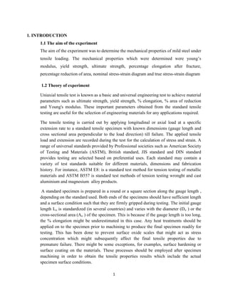


This document is a technical report detailing a tensile test performed on a mild steel specimen to determine its mechanical properties, including Young’s modulus, ultimate tensile strength, yield strength, and percentage elongation. The experiment was conducted at the University of Dar es Salaam, and results indicated that the specimen exhibited ductile behavior, culminating in a reduction of area at fracture. The report includes experimental methods, results, and discussions on potential sources of error and the effectiveness of the testing methodology.


![CONSTRUCTION [soil treatment, foundation backfill, Damp Proof Membrane[DPM] a...](https://cdn.slidesharecdn.com/ss_thumbnails/kahimba-181220112907-thumbnail.jpg?width=640&height=640&fit=bounds)