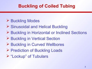
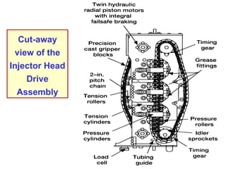
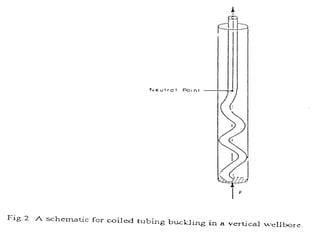
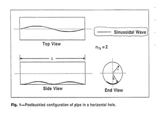
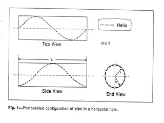
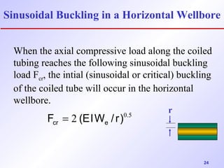
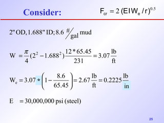
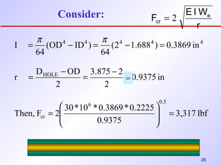
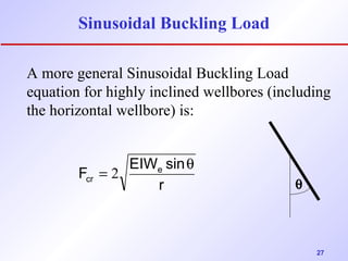
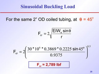
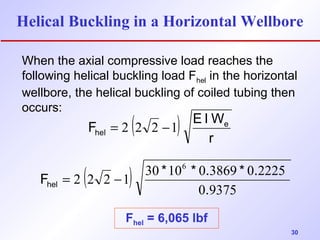
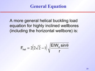
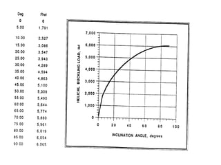
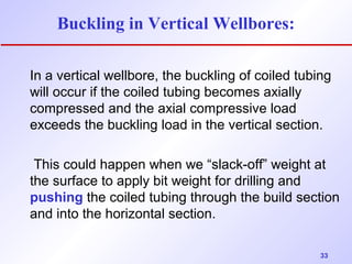
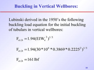
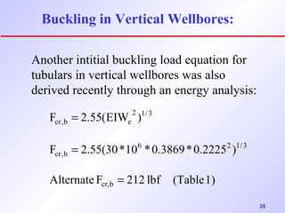
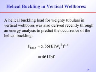
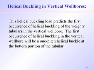
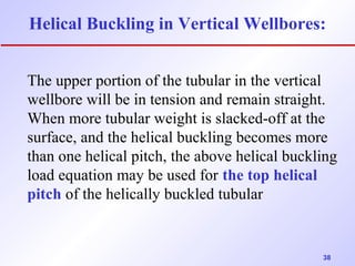
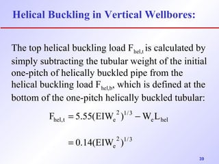
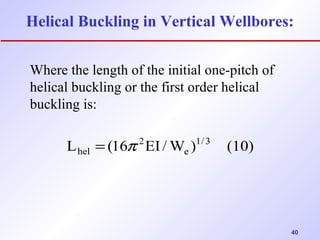
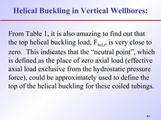
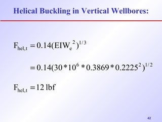
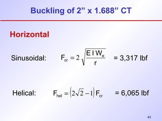
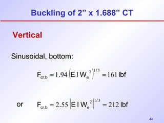
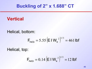
1 
PETE 411 
Well Drilling 
Lesson 37 
Coiled Tubing
2 
Coiled Tubing 
 What is Coiled Tubing? 
 Uses of Coiled Tubing 
 Properties of Coiled Tubing 
 Drilling with Coiled Tubing 
 Buckling
3 
Buckling of Coiled Tubing 
 Buckling Modes 
 Sinusoidal and Helical Buckling 
 Buckling in Horizontal or Inclined Sections 
 Buckling in Vertical Section 
 Buckling in Curved Wellbores 
 Prediction of Buckling Loads 
 “Lockup” of Tubulars
Truck-Mounted Coiled 
Tubing Reel Assembly 
4
5 
Coiled Tubing Reel Assembly
6
7
8
9 
Hydraulic Coiled Tubing Unit
10 
Cut-away 
view of the 
Injector Head 
Drive 
Assembly
11
12
13
Some Applications of Coiled Tubing 
• Cementing 
• Plug Cementing (e.g. P&A) 
• Squeeze Cementing 
• Logging 
• Drilling 
• Producing 
• Fishing 
• Scale Removal 
Ref: SPE Reprint Series NO. 38 “Coiled Tubing Technology” 
14
15 
Sidetrack Procedure
From 
OGJ 
July 8, 
2002 
p.62 
Coil 
Tubing 
Drilling on 
the North 
Slope 
16
17 
Coil Tubing Drilling on the North Slope 
 Drilling Rates routinely in excess of 
250 ft/hr - drilling in sandstone 
 Laterals longer than 2,500 ft 
 Good incremental oil production 
 Used electrical umbilical for MWD 
 Used mud motors and 3 ¾-in PDC bits
18 
Advantages 
 No rig required 
 No connections - fast tripping 
Disadvantages 
 Fatigue life limit (cycles) 
 Pressure and tension 
 Diameter and ovality
19 
Reference: 
“Coiled Tubing Buckling Implication in 
Drilling and Completing Horizontal Wells” 
by Jiang Wu and H.C. Juvkam-Wold, SPE 
Drilling and Completion, March, 1995.
20
21
22
23
Sinusoidal Buckling in a Horizontal Wellbore 
When the axial compressive load along the coiled 
tubing reaches the following sinusoidal buckling 
load Fcr, the intial (sinusoidal or critical) buckling 
of the coiled tube will occur in the horizontal 
wellbore. 
24 
2 0.5 
cr e F = (EIW / r) 
r
25 
Consider: 
= p - = 
(2 1.688 )12*65.45 
4 
2.67 lb 
W 3.07 1 8.6 
ö çè= - æ - 
E 30,000,000 psi (steel) 
3.07 lb 
0.2225 lb 
ft 
ft 
65.45 
ft 
231 
W 
gal mud 
2" OD, 1.688" ID; 8.6 # 
e 
2 2 
= 
= = ÷ø 
in 
* 
2 0.5 
Fcr = (EIWe / r)
F E IWe 
cr = 2 
3.317 lbf 
26 
= p - = p - = 
= - = 3.875 - 2 
- 
r D HOLE 
OD 
Then, F 2 30*10 *0.3869*0.2225 
0.9375 
0.9375 in 
2 
2 
(2 1.688 ) 0.3869 in 
64 
(OD ID ) 
64 
I 
6 0.5 
cr 
4 4 4 4 4 
ö 
= ÷ ÷ø 
ç çè æ 
= 
Consider: 
, 
= 
r
27 
Sinusoidal Buckling Load 
A more general Sinusoidal Buckling Load 
equation for highly inclined wellbores (including 
the horizontal wellbore) is: 
F EIWe sin 
cr 
= 2 q 
r q
28 
Sinusoidal Buckling Load 
For the same 2” OD coiled tubing, at q = 45o 
F EIWe sin 
cr 
= 2 q 
r 
6 0 5 
F * * . * . sin ÷ ÷ø 
2 30 10 0 3869 0 2225 45 
0 9375 
o . 
cr . 
ö 
ç çè æ 
= 
Fcr = 2,789 lbf
29
Helical Buckling in a Horizontal Wellbore 
When the axial compressive load reaches the 
following helical buckling load Fhel in the horizontal 
wellbore, the helical buckling of coiled tubing then 
occurs: ( ) r 
30 
F E IWe 
hel = 2 2 2 -1 
( ) 0 9375 
6 
F = - 
* * . * . hel 2 2 2 1 30 10 0 3869 0 2225 
. 
Fhel = 6,065 lbf
31 
General Equation 
A more general helical buckling load 
equation for highly inclined wellbores 
(including the horizontal wellbore) is: 
( ) r 
F EIWe sin 
hel 
= 2 2 2 -1 q
32
33 
Buckling in Vertical Wellbores: 
In a vertical wellbore, the buckling of coiled tubing 
will occur if the coiled tubing becomes axially 
compressed and the axial compressive load 
exceeds the buckling load in the vertical section. 
This could happen when we “slack-off” weight at 
the surface to apply bit weight for drilling and 
pushing the coiled tubing through the build section 
and into the horizontal section.
34 
Buckling in Vertical Wellbores: 
Lubinski derived in the 1950’s the following 
buckling load equation for the initial buckling 
of tubulars in vertical wellbores: 
= 
F 1.94(EIW ) 
= 
F 1.94(30*10 *0.3869*0.2225 ) 
F 161 lbf 
cr,b 
6 2 1/3 
cr,b 
2 1/3 
cr,b e 
=
35 
Buckling in Vertical Wellbores: 
Another intitial buckling load equation for 
tubulars in vertical wellbores was also 
derived recently through an energy analysis: 
= 
F 2.55(EIW ) 
F 2.55(30*10 *0.3869*0.2225 ) 
Alternate F 212 lbf (Table 1) 
cr,b 
6 2 1/3 
cr,b 
2 1/3 
cr,b e 
= 
=
36 
Helical Buckling in Vertical Wellbores: 
A helical buckling load for weighty tubulars in 
vertical wellbores was also derived recently through 
an energy analysis to predict the occurrence of the 
helical buckling: 
F 5.55(EIW 2 )1/3 
hel,b e 
461 lbf 
= 
=
Helical Buckling in Vertical Wellbores: 
37 
This helical buckling load predicts the first 
occurrence of helical buckling of the weighty 
tubulars in the vertical wellbore. The first 
occurrence of helical buckling in the vertical 
wellbore will be a one-pitch helical buckle at 
the bottom portion of the tubular.
Helical Buckling in Vertical Wellbores: 
The upper portion of the tubular in the vertical 
wellbore will be in tension and remain straight. 
When more tubular weight is slacked-off at the 
surface, and the helical buckling becomes more 
than one helical pitch, the above helical buckling 
load equation may be used for the top helical 
pitch of the helically buckled tubular 
38
39 
Helical Buckling in Vertical Wellbores: 
The top helical buckling load Fhel,t is calculated by 
simply subtracting the tubular weight of the initial 
one-pitch of helically buckled pipe from the 
helical buckling load Fhel,b, which is defined at the 
bottom of the one-pitch helically buckled tubular: 
= - 
F 5.55(EIW ) W L 
2 1/3 
e 
e hel 
2 1/3 
hel,t e 
0.14(EIW ) 
=
Helical Buckling in Vertical Wellbores: 
40 
Where the length of the initial one-pitch of 
helical buckling or the first order helical 
buckling is: 
L (16 EI /W )1/3 (10) 
e 
2 
hel = p
Helical Buckling in Vertical Wellbores: 
From Table 1, it is also amazing to find out that 
the top helical buckling load, Fhel,t, is very close to 
zero. This indicates that the “neutral point”, which 
is defined as the place of zero axial load (effective 
axial load exclusive from the hydrostatic pressure 
force), could be approximately used to define the 
top of the helical buckling for these coiled tubings. 
41
Helical Buckling in Vertical Wellbores: 
42 
2 1/3 
= 
F 0.14(EIW ) 
0.14(30*10 *0.3869*0.2225 ) 
= 
F 12 lbf 
hel,t 
6 2 1/ 2 
hel,t e 
=
Sinusoidal: cr = 2 = 3,317 lbf 
43 
Buckling of 2” x 1.688” CT 
Horizontal 
F E IWe 
r 
hel ( ) cr F = 2 2 -1 F 
Helical: = 6,065 lbf
44 
Buckling of 2” x 1.688” CT 
Vertical 
Sinusoidal, bottom: 
or 
F = 1 . 94 (E IW 2 ) 1 / 
3 = 
cr,b e 161 lbf F = 2 . 55 (E IW 2 ) 1 / 
3 = 
cr,b e 212 lbf
45 
Buckling of 2” x 1.688” CT 
Vertical 
Helical, bottom: 
F . (E IW ) lbf / 
Helical, top: 
hel,b 5 55 e 461 2 1 3 = = 
F = 0 . 14 (E IW 2 ) 1 / 
3 = 
hel,b e 12 lbf

Tech drilling-coil tubing

  • 1.
    1 PETE 411 Well Drilling Lesson 37 Coiled Tubing
  • 2.
    2 Coiled Tubing  What is Coiled Tubing?  Uses of Coiled Tubing  Properties of Coiled Tubing  Drilling with Coiled Tubing  Buckling
  • 3.
    3 Buckling ofCoiled Tubing  Buckling Modes  Sinusoidal and Helical Buckling  Buckling in Horizontal or Inclined Sections  Buckling in Vertical Section  Buckling in Curved Wellbores  Prediction of Buckling Loads  “Lockup” of Tubulars
  • 4.
  • 5.
    5 Coiled TubingReel Assembly
  • 6.
  • 7.
  • 8.
  • 9.
    9 Hydraulic CoiledTubing Unit
  • 10.
    10 Cut-away viewof the Injector Head Drive Assembly
  • 11.
  • 12.
  • 13.
  • 14.
    Some Applications ofCoiled Tubing • Cementing • Plug Cementing (e.g. P&A) • Squeeze Cementing • Logging • Drilling • Producing • Fishing • Scale Removal Ref: SPE Reprint Series NO. 38 “Coiled Tubing Technology” 14
  • 15.
  • 16.
    From OGJ July8, 2002 p.62 Coil Tubing Drilling on the North Slope 16
  • 17.
    17 Coil TubingDrilling on the North Slope  Drilling Rates routinely in excess of 250 ft/hr - drilling in sandstone  Laterals longer than 2,500 ft  Good incremental oil production  Used electrical umbilical for MWD  Used mud motors and 3 ¾-in PDC bits
  • 18.
    18 Advantages No rig required  No connections - fast tripping Disadvantages  Fatigue life limit (cycles)  Pressure and tension  Diameter and ovality
  • 19.
    19 Reference: “CoiledTubing Buckling Implication in Drilling and Completing Horizontal Wells” by Jiang Wu and H.C. Juvkam-Wold, SPE Drilling and Completion, March, 1995.
  • 20.
  • 21.
  • 22.
  • 23.
  • 24.
    Sinusoidal Buckling ina Horizontal Wellbore When the axial compressive load along the coiled tubing reaches the following sinusoidal buckling load Fcr, the intial (sinusoidal or critical) buckling of the coiled tube will occur in the horizontal wellbore. 24 2 0.5 cr e F = (EIW / r) r
  • 25.
    25 Consider: =p - = (2 1.688 )12*65.45 4 2.67 lb W 3.07 1 8.6 ö çè= - æ - E 30,000,000 psi (steel) 3.07 lb 0.2225 lb ft ft 65.45 ft 231 W gal mud 2" OD, 1.688" ID; 8.6 # e 2 2 = = = ÷ø in * 2 0.5 Fcr = (EIWe / r)
  • 26.
    F E IWe cr = 2 3.317 lbf 26 = p - = p - = = - = 3.875 - 2 - r D HOLE OD Then, F 2 30*10 *0.3869*0.2225 0.9375 0.9375 in 2 2 (2 1.688 ) 0.3869 in 64 (OD ID ) 64 I 6 0.5 cr 4 4 4 4 4 ö = ÷ ÷ø ç çè æ = Consider: , = r
  • 27.
    27 Sinusoidal BucklingLoad A more general Sinusoidal Buckling Load equation for highly inclined wellbores (including the horizontal wellbore) is: F EIWe sin cr = 2 q r q
  • 28.
    28 Sinusoidal BucklingLoad For the same 2” OD coiled tubing, at q = 45o F EIWe sin cr = 2 q r 6 0 5 F * * . * . sin ÷ ÷ø 2 30 10 0 3869 0 2225 45 0 9375 o . cr . ö ç çè æ = Fcr = 2,789 lbf
  • 29.
  • 30.
    Helical Buckling ina Horizontal Wellbore When the axial compressive load reaches the following helical buckling load Fhel in the horizontal wellbore, the helical buckling of coiled tubing then occurs: ( ) r 30 F E IWe hel = 2 2 2 -1 ( ) 0 9375 6 F = - * * . * . hel 2 2 2 1 30 10 0 3869 0 2225 . Fhel = 6,065 lbf
  • 31.
    31 General Equation A more general helical buckling load equation for highly inclined wellbores (including the horizontal wellbore) is: ( ) r F EIWe sin hel = 2 2 2 -1 q
  • 32.
  • 33.
    33 Buckling inVertical Wellbores: In a vertical wellbore, the buckling of coiled tubing will occur if the coiled tubing becomes axially compressed and the axial compressive load exceeds the buckling load in the vertical section. This could happen when we “slack-off” weight at the surface to apply bit weight for drilling and pushing the coiled tubing through the build section and into the horizontal section.
  • 34.
    34 Buckling inVertical Wellbores: Lubinski derived in the 1950’s the following buckling load equation for the initial buckling of tubulars in vertical wellbores: = F 1.94(EIW ) = F 1.94(30*10 *0.3869*0.2225 ) F 161 lbf cr,b 6 2 1/3 cr,b 2 1/3 cr,b e =
  • 35.
    35 Buckling inVertical Wellbores: Another intitial buckling load equation for tubulars in vertical wellbores was also derived recently through an energy analysis: = F 2.55(EIW ) F 2.55(30*10 *0.3869*0.2225 ) Alternate F 212 lbf (Table 1) cr,b 6 2 1/3 cr,b 2 1/3 cr,b e = =
  • 36.
    36 Helical Bucklingin Vertical Wellbores: A helical buckling load for weighty tubulars in vertical wellbores was also derived recently through an energy analysis to predict the occurrence of the helical buckling: F 5.55(EIW 2 )1/3 hel,b e 461 lbf = =
  • 37.
    Helical Buckling inVertical Wellbores: 37 This helical buckling load predicts the first occurrence of helical buckling of the weighty tubulars in the vertical wellbore. The first occurrence of helical buckling in the vertical wellbore will be a one-pitch helical buckle at the bottom portion of the tubular.
  • 38.
    Helical Buckling inVertical Wellbores: The upper portion of the tubular in the vertical wellbore will be in tension and remain straight. When more tubular weight is slacked-off at the surface, and the helical buckling becomes more than one helical pitch, the above helical buckling load equation may be used for the top helical pitch of the helically buckled tubular 38
  • 39.
    39 Helical Bucklingin Vertical Wellbores: The top helical buckling load Fhel,t is calculated by simply subtracting the tubular weight of the initial one-pitch of helically buckled pipe from the helical buckling load Fhel,b, which is defined at the bottom of the one-pitch helically buckled tubular: = - F 5.55(EIW ) W L 2 1/3 e e hel 2 1/3 hel,t e 0.14(EIW ) =
  • 40.
    Helical Buckling inVertical Wellbores: 40 Where the length of the initial one-pitch of helical buckling or the first order helical buckling is: L (16 EI /W )1/3 (10) e 2 hel = p
  • 41.
    Helical Buckling inVertical Wellbores: From Table 1, it is also amazing to find out that the top helical buckling load, Fhel,t, is very close to zero. This indicates that the “neutral point”, which is defined as the place of zero axial load (effective axial load exclusive from the hydrostatic pressure force), could be approximately used to define the top of the helical buckling for these coiled tubings. 41
  • 42.
    Helical Buckling inVertical Wellbores: 42 2 1/3 = F 0.14(EIW ) 0.14(30*10 *0.3869*0.2225 ) = F 12 lbf hel,t 6 2 1/ 2 hel,t e =
  • 43.
    Sinusoidal: cr =2 = 3,317 lbf 43 Buckling of 2” x 1.688” CT Horizontal F E IWe r hel ( ) cr F = 2 2 -1 F Helical: = 6,065 lbf
  • 44.
    44 Buckling of2” x 1.688” CT Vertical Sinusoidal, bottom: or F = 1 . 94 (E IW 2 ) 1 / 3 = cr,b e 161 lbf F = 2 . 55 (E IW 2 ) 1 / 3 = cr,b e 212 lbf
  • 45.
    45 Buckling of2” x 1.688” CT Vertical Helical, bottom: F . (E IW ) lbf / Helical, top: hel,b 5 55 e 461 2 1 3 = = F = 0 . 14 (E IW 2 ) 1 / 3 = hel,b e 12 lbf