SlideShare a Scribd company logo
1 of 77
Savitribai Phule Pune University
KVNNIEER, Nashik, Department of Mechanical Engineering
1
CHAPTER 1
1.INTRODUCTION:
In present condition many electrically operated power hacksaw machines of different
companies with different specifications are available for the use in shop floor. These
machines are so precise that they can cut metal bars with minimum time made up of
different materials but they have one and major disadvantage that those are able to cut
single piece of bar at a time. For industries to achieve the mass production, it is
necessary to cut metal bars with high rate. So it is impossible to depend upon
conventional single frame power hacksaw machines and need the improvement in
technology and design of such machines. With the help of this multi-way hacksaw
machine the four metal bars can be cut simultaneously to get high speed cutting rate and
to achieve mass production for maximum profit in related companies. As this machine
overcomes all the limitations and drawbacks of conventional hacksaw machines, it is
also helpful for small scale industries due to its simple working and operating
conditions along with its compatibility, efficiency and affordable price.
A hacksaw is a fine-toothed saw, originally and principally for cutting metal. They can
also cut various other materials, such as plastic and wood for example, plumbers and
electricians often cut plastic pipe and plastic conduit with them. There are hand saw
versions and powered versions (power hacksaws). Most hacksaws are hand saws with a
C-shaped frame that holds a blade under tension. Such hacksaws have a handle, usually
a pistol grip, with pins for attaching a narrow disposable blade. The frames may also be
adjustable to accommodate blades of different sizes. A screw or other mechanism is
used to put the thin blade under tension. Panel hacksaws forgo the frame and instead
have a sheet metal body; they can cut into a sheet metal panel further than a frame
would allow. These saws are no longer commonly available, but hacksaw blade holders
enable standard hacksaw blades to be used similarly to a keyhole saw or pad saw.
Savitribai Phule Pune University
KVNNIEER, Nashik, Department of Mechanical Engineering
2
Power tools including nibblers, jigsaws, and angle grinders fitted with metal-cutting
blades and discs are now used for longer cuts in sheet metals.
On hacksaws, as with most frame saws, the blade can be mounted with the teeth facing
toward or away from the handle, resulting in cutting action on either the push or pull
stroke. In normal use, cutting vertically downwards with work held in a bench vice,
hacksaw blades should be set to be facing forwards. Some frame saws, including Fret
Saws and Piercing Saws, have their blades set to be facing the handle because they are
used to cut by being pulled down against a horizontal surface.
Cutting is a widely used machining process in manufacturing. Therefore, an optimal
selection of cutting parameters to satisfy an economic objective within the constraints of
Cutting operation plays a very important role. To determine the optimal cutting
parameters, reliable mathematical models have to be formulated to associate the cutting
parameters with the cutting performance. However, it is also well known that reliable
mathematical models are not easy to obtain. In any optimization problem, it is very
crucial to identify the prime objective called as the objective function or optimization
criterion. In manufacturing processes, Basically, this optimization procedure, whenever
carried out, involves partial differentiation for the minimization of unit cost,
maximization of production rate or maximization of profit rate. These manufacturing
conditions are expressed as a function of cutting speed. Then, the optimum cutting
speed is determined by equating the partial differentiation of the expressed function to
zero. This is not an ideal approach to the problem of obtaining an economical metal
cutting. The other cutting variables, particularly the feed rate also have an important
effect on cutting economics. Therefore, it is necessary to optimize the cutting speed and
feed rate simultaneously in order to obtain an economical metal cutting operation. The
process of the metal cutting depends upon the features of tools, input work materials
and machine parameter settings influencing process efficiency and output quality
characteristics or responses. A significant improvement in process efficiency may be
obtained by process parameters optimization that identifies and determines the regions
Savitribai Phule Pune University
KVNNIEER, Nashik, Department of Mechanical Engineering
3
of critical process control factors leading to desired outputs or responses with
acceptable variation.Cutting processes work by causing fracture of the material that is
processed. Usually, the portion that is fractured away is in small sized pieces, called
chips. Common cutting processes include sawing, shaping (or planning), broaching,
drilling, grinding, turning and milling. Although the actual machines, tools and
processes for cutting look very different from each other, the basic mechanism for
causing the fracture can be understood by just a simple model called for orthogonal
cutting.
In all machining processes, the workpiece is a shape that can entirely cover the final part
shape. The objective is to cut away the excess material and obtain the final part. This
cutting usually requires to be completed in several steps – in each step, the part is held in
a fixture, and the exposed portion can be accessed by the tool to machine in that portion.
Common fixtures include vise, clamps, 3-jaw or 4-jaw chucks, etc. Each position of
holding the part is called a setup. One or more cutting operations may be performed,
using one or more cutting tools, in each setup.
What Is Optimization??
Optimum selection of cutting conditions importantly contribute to the increase of
productivity by minimization of production time and the associated costs, therefore
utmost attention is paid to this problem in this contribution. Time is the most important
parameter in any operation and all the manufacturing firms aim at producing a product
in minimum time to reach the customer quickly and enhance the customer satisfaction.
This can be achieved by using optimization techniques. The success of an optimization
technique does not lie in its complexity but the time in which it provides a solution to
the manufacturing firms. In this research paper, a geometric programming based
approach to optimize the production time of the cutting process within in some
operating constraints is proposed. It involves mathematical modeling for production
time of cutting process, which is expressed as a function of the cutting parameters
which include the cutting speed and feed rate. Then, the developed mathematical model
Savitribai Phule Pune University
KVNNIEER, Nashik, Department of Mechanical Engineering
4
was optimized with in some operating constraints like the maximum cutting speed,
maximum feed rate, power constraint and the surface roughness constraint. The results
of the model reveal that the proposed method provides a systematic and efficient
technique to obtain the optimal cutting parameters that will minimize the production
time of cutting process. Thus, it is possible to optimize the production time of
Cuttingprocess effectively by geometric programming. The approach is suitable for fast
determination of optimum cutting parameters during machining, where there is not
enough time for deep analysis.
Optimum selection of cutting conditions importantly contribute to the increase of
productivity by minimization of production time and the associated costs, therefore
utmost attention is paid to this problem in this contribution. Time is the most important
parameter in any operation and all the manufacturing firms aim at producing a product
in minimum time to reach the customer quickly and enhance the customer satisfaction.
This can be achieved by using optimization techniques. The success of an optimization
technique does not lie in its complexity but the time in which it provides a solution to
the manufacturing firm.the cutting parameters which include the cutting speed and feed
ratethe cutting parameters which include the cutting speed and feed rate.
Optimization Techniques Development
Kirkpatrick et al. (1983) reviewed the central constructs in combinatorial optimization
and in statistical mechanics and then develops the similarities between the two fields.
They showed how Metropolis algorithm for approximate numerical simulation of the
behavior of a many-body system at a finite temperature provides a natural tool for
bringing the techniques of statistical mechanics to bear on optimization. Application of
this technique to partitioning, component placement and wiring of electronics systems
have presented. Travelling salesman problem has considered to test the robustness of
SAT. Feng-Tse Lin et al. (1993) presented a stochastic approach called the annealing-
genetic algorithm for solving combinatorial optimization problems. This approach
incorporates GA into SA to improve the performance of SA. Ulrich (1994)
Savitribai Phule Pune University
KVNNIEER, Nashik, Department of Mechanical Engineering
5
demonstrated that the performance of simulated annealing strongly depends on the
annealing schedule. An attempt has been made to optimize the annealing schedule. 21
Mandira and Uday (1997) applied GA and SA to the problem of optimal link
enhancement, which is an Non deterministic Polynomial (NP) complete combinatorial
optimization problem in the topological expansion of computer communication
networks and showed that simulated annealing outperforms genetic algorithm on this
problem. Prasad et al. (1997) reports the development of an optimization module for
determining process parameters for turning operations as part of a personnel computer
based generative CAPP system. Improved mathematical models are formulated by
modifying the tolerance and work-piece rigidity constraints for multi-pass turning
operations. The formulated models are solved by the combination of geometric and
linear programming techniques. Cai and Zhou (1997) examined the problem of
sequencing a set of jobs on a single machine, where each job has a random processing
time and is associated with a known job-dependent weight, with the objective to
minimize the expectation of the weighted variance of job completion times. Established
the NP-completeness of this problem, and further show that the problem under some
compatible conditions is NP-complete in the ordinary sense and introduced the concept
of a W-shaped solution for the problem and find that an optimal W-shaped sequence
exists under the compatible conditions. A method incorporating a combination of expert
system and mathematical programming is proposed by Kim and Suh (1998) to produce
an optimal operation sequence to minimizing the non cutting time. Also precedence,
tolerance and alternative operations are taken into consideration as constraints. The
mathematical method performs grouping and sequencing simultaneously and the expert
system preprocesses the procedure by eliminating infeasible solution sets and clustering
the operations according to 22 the tool commonalities. A prototype CAPP system was
also developed using an object oriented expert system shell. Hildegard and Gerhard
(1998) have used SA to the Order Spread Minimization Problem in the process of
planning industrial cutting operations and it can be looked upon as a generalization of
the Traveling Salesman Problem (TSP), it has to be classified as NP-complete. SA
Savitribai Phule Pune University
KVNNIEER, Nashik, Department of Mechanical Engineering
6
appears to provide solutions which - in terms of solution quality - are equivalent to
previous work reported. Claimed that SA provides significantly improved solutions at
the expense of a moderate increase in computing times.Rui-Rong Wu and He-Ming
Zhang (1998) have employed objectoriented technology to represent set-up planning
knowledge and generate alternative set-ups which can respond to the dynamic
manufacturing resource and facilitate the CAPP / production planning systems (PPS)
integration. Based on fuzzy-set theory, a fuzzy evaluation function is proposed to
produce optimal set-ups. Combined with a real project, a setup planning system is
developed to generate alternative and optimal set-up plans for the machining of
prismatic parts. Klaus Neumann and Jurgen Zimmermann (1998) presented polynomial
heuristic procedures for NP-hard stochastic scheduling problems with identical parallel
machines and objective functions where stochastic precedence constraints are given by
special acyclic networks. To develop appropriate heuristics for scheduling problems
with uniform parallel machines and more general objective functions needed further
studies. Ronald et al. (2001) conducted empirical research on heuristics. The toughest
technical challenges are finding (or generating) suitable test instances, and assessing
how close heuristic algorithms come to optimal. No investigation can hope to produce
useful results if these matters are not 23 addressed early and intensively. The rest of the
procedures for conducting, analyzing and reporting empirical results can usually be
boiled down to fairness and common sense. Formal statistics may help some analyses,
but a well-conceived graph can do just as well. If adequate thought and effort is devoted
to understanding what the research is about, what results are hidden in the experimental
out comes, and how these findings can be fairly and effectively communicated, every
study can contribute something to the critical but still underdeveloped science of
heuristic algorithms. Mitsunori et al. (2002) dealt with the two problems in SA. One is
the long computational time of the numerical annealing, and the solution to it is the
parallel processing of SA. The other one is the determination of an adaptive mechanism
for changing the temperature. The multiple SA processes are performed in multiple
processors, and the temperatures in the SA processes are determined by a genetic
Savitribai Phule Pune University
KVNNIEER, Nashik, Department of Mechanical Engineering
7
algorithm for a TSP problem. The classical version of SA is based on a cooling
schedule. Generally, the initial temperature is set such that the acceptance ratio of bad
moves is equal to a certain value. Walid Ben-Ameur et al. (2004) proposed a simple
algorithm to compute a temperature which is compatible with a given acceptance ratio.
Then, the properties of the acceptance probability are showed this function is convex for
low temperatures and concave for high temperatures. Also provided a lower bound for
the number of plateaux of a SA based on a geometric cooling schedule and many
numerical experiments are reported. BalramSuman (2004) used four SA based multi-
objective algorithms to solve multi-objective optimization of constrained problems with
varying degree of complexity along with a new algorithm. The algorithm uses a strategy
of Pareto dominant based fitness in the acceptance criteria of SA and is improved. 24
Based on the various constraints in process route sequencing and the astringency of GA,
the GA was reconstructed by Zhang Wei Bo (2006), including the establishing of the
coding strategy, the evaluation operator and the fitness function. The natural number is
adopted in coding strategy, the ‘‘elitist model’’ and the ‘‘tournament selection’’ are
adopted as selection operators, the nonconforming sequential searching crossover
operator is used and the inconsistent mutation operator is adopted, the fitness function is
defined as a formula of the sum of compulsive constraints with each weighing, and
these constraints are used as the control strategy for GAs in the searching process. By
using GAs in the optimization, the optimal or nearoptimal process route is obtained. To
solve the job-shop scheduling problem (JSSP) more effectively an immune GA was
proposed and presented by Xiao-Dong and Cong-Xin (2007) via combining the immune
theory and the GA. A modified precedence operation crossover was also proposed to
improve the performance of the crossover operator. On the other hand, the “shortest
processing time” principle was selected to the vaccine and the design method of the
immune operator was given at the same time. Finally, the performance was validated by
applying to benchmark problems.
Savitribai Phule Pune University
KVNNIEER, Nashik, Department of Mechanical Engineering
8
Different Types Of Hacksaw Machine For Optimization
1. Model No. CE 1
Manufacture by :- Creative Engineers, Rajkot
Cost of machine :- 45000/-
Having following specification
Table No.1.1 Specification of Model CE 1 Machine
Particulars Cutting
capacity
Blade size
(mm)
Motor
HP
Cutting
Stroke/min
CE 1 75 mm 300/12 0.5 60-75
CE 1 machine having following features
i. High speed machine for fast and bulk cutting
ii. Higher accuracy
iii. Less vibration
Savitribai Phule Pune University
KVNNIEER, Nashik, Department of Mechanical Engineering
9
Fig. No1.1. Hacksaw Machine Model No CE 1
2. Power Metal Hacksaw Machine
Manufacture by :-Vishwacon Engineers Pvt Ltd, Ahemedabad
Cost of machine :- 50000/-
Machine Having following specification
Table No. 1.2 Specification of Power Metal Hacksaw Machine
Motor speed
(rpm)
Cutting
capacity
Blade size
(mm)
Motor
HP
Cutting
Stroke/min
1440 45mm 300/12 1.5 80-85
Savitribai Phule Pune University
KVNNIEER, Nashik, Department of Mechanical Engineering
10
Fig. No.1.2Power Metal Hacksaw Machine
1.4 Hydraulic Hacksaw Machine
Manufacture by :-Yash Machine Tool, Ahmedabad
Cost of machine :- 43000/-
Having following specification
Table No. 1.3Specification of Hydraulic Hacksaw Machine
Motor speed
(rpm)
Cutting
capacity
Blade size
(mm)
Motor
HP
Cutting
Stroke/min
1440 60 400/32 1 80-85
Savitribai Phule Pune University
KVNNIEER, Nashik, Department of Mechanical Engineering
11
Fig No.1.3Hydraulic Hacksaw Machine
1.1 Problem Statement :
The power hacksaw machines, which are operated by human operators as mentioned,
have the demerit of unloading and loading the work-piece many times. In industries
manufacturing pumps, these machines are used to cut the motor shafts to the required
lengths. It will be difficult for the operator if he has been assigned to cut a huge quantity
of motor shafts and he has to measure the lengths each time for cutting. Since humans
are not as versatile as machines, there is a possibility that there may be inaccuracies.
Besides, if there is a slight time delay in between every cycle of cutting a piece, the
cumulative delay in time will be found to have a considerable magnitude, which might
have been utilized properly if the proposed machine were in use there.To cut different
metal bar pieces with high rate andaccuracy to minimize an idle time.
1.2Objectives :
The most commonly used objective function is the specific cost.Walvekar and Lambert
used geometric programming for the selection of machining variables. The optimum
values of both cutting speed and feed rate were found out as a function of depth of cut
Savitribai Phule Pune University
KVNNIEER, Nashik, Department of Mechanical Engineering
12
in multi-pass Cutting operations .analyzed the problem of optimum cutting parameters
selection by finding out the optimal cutting speed which satisfies the basic
manufacturing criterion.
We have optimize the hack saw machine model of C.E. 1 with it’s present specification
and in lower of cost. And taking extra development in the present hack saw machine.
1.3 Scope :
Four way hack saw machine is very effective for small scale industry because its
manufacturing cost is very less. And it cut four work piece at one time in same power as
compare to power hack saw, therefore the cutting cost are reduces therefore overall
production cost is reduced.
1.4 Methodology :
This project consists of single phase vertical electric motor rigidly placed at the center
of metallic foundation provided. The shaft of motor rotates at 1440 rpm with the power
0.5 HP The circular disc is mounted on the shaft of motor with the help of key and key
slot arrangement. The eccentric point on the plane of disc is provided such that the
desired cutting stroke is achieved (around 4-5 inches). One end of each connecting rod
is pivoted at this eccentric point by the use of suitable bearing. Another end of each rod
is connected to the hacksaw blade fame with thehelp of universal joint to get vertical
and horizontal Degree of Freedom of rotation for the proper cutting operation. The
hacksaw frame slides on the guide ways provided. When motor is ON and disc starts
rotating, due to the reciprocating motion of hacksaw frame the metal rod is cut which is
firmly fixed in vise. The automatic feeding of coolant is provided to reduce heat
generated due to friction which also avoids.
1.5 Organization of Dissertation
We are conducting project development and its construction and fabrication workshop
at our college also where will have possible it’s helpful for our project.
Savitribai Phule Pune University
KVNNIEER, Nashik, Department of Mechanical Engineering
13
PROCESS FLOW CHART
Market Survey Of Different Type Of Hacksaw Machine
Selecting The One Hacksaw Machine That To Be Optimized
Preparation of The Designed Of Hacksaw Machine
Selection Of Materials For Different Parts Of Hacksaw Machine
Purchasing The Various Parts Of Machine
Selection Of Manufacturing Process
Assembling Of Multi-Way Hacksaw Machine
Testing of Machine for preparation of Optimization process
Calculating the Various Type Of Parameters Which Is Subjected To Optimization Process
Chart No.1.5.1.Process Flow Chart
Savitribai Phule Pune University
KVNNIEER, Nashik, Department of Mechanical Engineering
14
CHAPTER 2
2.1 Literature Review :
Prof.KshirsagarPrashant R., RathodHarayan J., RahatePrashant P., HalayePrashantP.,
SurveSahine design and theoretical analysis of multi way power hacksaw
machine.There are many industrial applications where round bar or square bars are
required to be operated on different machines to make machine components such as
Shafts, Bolts, Screws etc. This needs more and more number of pieces to be cut for
mass production of those components. To achieve this goal the Multi-way power
hacksaw machine is developed. This paper proposes the model of multi-way hacksaw
machine which is able to cut four pieces simultaneously without any jerk and minimum
vibrations. The model implies conversion of rotary motion into the reciprocating motion
for proper working of hacksaw. This model overcomes the limitations of conventional
hacksaw machines which can cut single piece at a time. It is able to cut metal bars of
different materials at same time and will be helpful in many industries due its
compatibility, reliability and efficiency.[01]
Prof. Nitinchandra R. Patel, Ravi Thakkar, MiteshkumarRathwa in his research paper
“Material selection and testing of hacksaw blade based on mechanical properties” stated
that the appropriate saw blade must be selected for better operation and fine cutting by
selecting number of teeth per inch. There are four types of blades based on material
namely High Carbon steel, Alloy Steel, Bi-metallic strip and High speed steel blades.
Out of these four the best suitable for cutting hard materials like Mild steel bar and
Aluminum is Bi-metallic blade on the basis of Properties of materials, Wear resistance
and Cutting performance. Testing of different material blades like High Carbon Steel,
Low Alloy Steel, Bi-metallic blade, High speed Steel blades for their hardness, Cutting
time performance, Wear Resistance, Tensile Strength and performance under buckling.
Experiment of Rockwell Hardness tester for getting Hardness Number on C-Scale for
all different types of blades, so their relative hardness of teeth of different blade blades
can be compared. For Cutting Performance test, Cutting of same diameter (25mm) job
Savitribai Phule Pune University
KVNNIEER, Nashik, Department of Mechanical Engineering
15
of different materials like Aluminum, Brass, Copper by all blades and their cutting time
is noted and compared. For Wear Resistance ability, Profiles of blades-before and after
cutting are developed with the help of profile projector.[02]
D.V.Sabarinanda, V.Siddhartha, T.Mohanraj in their paper “Design and Fabrication of
Automated Hacksaw Machine” (April 2014) gives an idea about the various
components required for fabrication of the proposed model. These components will help
to get smooth working condition and future automation of different mechanical actions
as well as linkages. The objectives is to automate the conventional power hacksaw
machine in order to achieved high productivity of work-pieces than the power hacksaw
machine using microcontroller. The automated machine acquires two inputs from the
user namely the number of pieces to be cut and the length of each piece that is required
to be cut. The inputs are given by the user with the help of a keypad and an LCD
display, which will help the user to verify the data given by him. The operator need not
measure the length of the work-piece that is to be cut and to load and unload the work-
piece from the chuck each time after a piece has been cut. After acquiring the two
inputs from the user, the machine automatically feeds the given length of work-piece in
to a chuck and starts to cut till the given number of work-pieces has been cut. The
machine feeds the work-piece with the help of a conveyor, which is driven by a DC
motor and an IR sensor ensures that the feeding stops when the specified length has
been reached. A pneumatic cylinder is used for holding the work-piece when cutting
operation is done. An AC motor is used to bring about the reciprocating motion
required for cutting the work-pieces. There is a self-weight attached with the
reciprocating mechanism to provide the necessary downward force required for
penetration of hacksaw blade in to the work-piece. When a single piece has been cut, a
limit switch will get triggered by the self-weight mechanism, which is sensed by the
microcontroller to start the cyclic operation again provided if the specified number of
work-pieces has not been cut.[03]
Savitribai Phule Pune University
KVNNIEER, Nashik, Department of Mechanical Engineering
16
R. Subash, K. Samuel Jayakaran, (2014), In this paper author has designed Pedal
operated hacksaw machine which can be used for industrial applications and Household
needs in which no specific input energy or power is needed. This project consists of a
sprocket arrangement, the crank and slider mechanism, the chain drive. In the
mechanism, chain drive is directly connected to the hacksaw for the processing of
cutting the wooden blocks. The objective of the paper is using the conventional
mechanical process which plays a vital role. The main aim is to reduce the human effort
for machining various materials such as wooden blocks, steel, PVC etc.[04]
Girish T.,Parameswaramurthy D.(2014), In this paper author has designed to
development of conceptual model of water pumping and battery charging cross trainer
which is user friendly, easy to do exercise, save & stores the energy of the users muscle
efforts. When the human operates the lever and the pedal, the Centrifugal Pump is
actuated and the water is pumped from ground sump to the tank. At the same time the
attached dynamo (i.e., is mounted near the V-belt) operates and the mechanical energy
is converted in to electrical energy, the generated electrical energy is stored in battery
with the help of wires. The stored electrical energy is used when we are needed.
[05]
UmeshBokade, Zakiuddin Syed Kazi and Girish D Mehta, (2013), the author proposed
the designed model which will convert the dirty/saline water into pure/ potable water
using the renewable source of energy (i.e., Human power). The machine consists of a
human-powered flywheel motor using a bicycle-drive mechanism with speed-increasing
gearing and a flywheel, which drive the process unit though a spiral jaw clutch and
torque increasing gearing. The operator puts energy into the flywheel at a convenient
power level for about one minute. After enough energy is stored, pedaling is stopped
and the energy in the flywheel is made available to the process unit.[06]
DharwaChaitanyaKirtikumar designed and developed a multipurpose machine which
does not require electricity for several operations like cutting, grinding etc. This is a
human powered machine runs on chain drives mainly with human efforts. But if you
wanted to operate this machine by electric power this machine can also does that. It has
Savitribai Phule Pune University
KVNNIEER, Nashik, Department of Mechanical Engineering
17
some special attachment so use both human power as well as electric power. The design
is ideal for use in the developing world because it doesn’t require electricity and can be
built using metal base, chain, pulley ,rubber belt, grinding wheel, saw, bearing, foot
pedal (for operated by human) ,electric motor, chain socket.
[07]
S.G.Bahaley, Dr. A.U. Awate, S.V. Saharkar designed and fabricated a pedal powered
multipurpose machine. It is a human powered machine which is developed for lifting
the water to a height 10 meter and generates 14 Volt, 4 ampere of electricity in most
effective way. Power required for pedaling is well below the capacity of an average
healthy human being. The system is also useful for the work out purpose because
pedaling will act as a health exercise and also doing a useful work.[08]
Stephan Tambari, Dan Orawari Gloria, OrueneDiabi, Ayejan Victor designed and
fabrication of pedal power hacksaw cutting machine. The aim of this work is to develop
a modernized and less stressful operation for cutting woods metals and plastics material.
It is very useful for cutting PVC materials and can be used widely in furniture making
industries. This work also serve as an exercising machine for fitness while cutting it
uses the principle of slider crank mechanism which converts the rotary motion of
flywheel to the reciprocating motion of the hacksaw during its motion.The machine was
tested and continued to be very efficient with an ideal mechanical Advantage of 0.5
(less than 1), velocity ratio of 0.65 (less than 1), a power output of 5.72KW and an
efficiency of 76.9%, which makes it very adequate and capable for cutting.[09]
Prof.Zoeb Khan, Mr.Sushil Dopkar Designed and fabrication of human power wood
cutting machine.This is improved design of the human powered wood cutting machine
which gives the less efforts of man and commonly used in rural areas where there is no
power supply. The design ensures a smooth operation during the cutting process. The
cutting force is provided by means of chain drive, gear assembly and other kinematic
mechanism and all the parameter need to be optimized to get maximum cutting force.
This machine is used for heavy duty wood cutting process for multiple operations like
Savitribai Phule Pune University
KVNNIEER, Nashik, Department of Mechanical Engineering
18
furniture, farm equipment’s, workshop and construction areas etc. It is light in weight
and portable machine.[10]
Avilasha B.G., Dr.Ramakrishna D.S. designed the measurement of load acting on
machines and structures is important from many considerations. Accurate weighing of
commodities, applying known load on specimens being tested for strength, safe
operation of material handling equipment such as crane, determination of operating
loads are some examples. When the load or forces are to be measured, a load cell is to
be placed in the load path. Many times, it is not feasible to insert the load cell in the
load path. In such cases, using the machine member themselves for measuring load will
be advantageous. This dissertation work involves study Hack Saw machine where the
load measurement is essential. Investigation is carried out to study the feasibility of
using the member of the machine itself as load sensing member. The load measurement
involves identification of critical component in the load path. Many times, it is not
feasible to insert the load cell in the load path. In such cases, using the machine member
themselves for measuring load will be advantageous. This dissertation work involves
study Hack Saw machine where the load measurement is essential. Investigation is
carried out to study the feasibility of using the member of the machine itself as load
sensing member. The load measurement involves identification of critical component in
the load path. While the process of load measurement is not straightforward in case
where the known load is cannot be applied, inverse FEM is to be adopted for the case
where applied load is not known. Once the critical component in the load path is
identified, electrical resistance strain gauges are mounted in an appropriate fashion to
get maximum output for an applied load. The dynamic strain was recorded using the
LABVIEW software. The finite element analysis done for hacksaw machine with
proper boundary conditions and the strain data are taken for series of loads and then
these values are compared with the experimental strain value and the unknown load was
estimated.[11]
Savitribai Phule Pune University
KVNNIEER, Nashik, Department of Mechanical Engineering
19
Umesh Bokade, Zakiuddin Syed Kazi and Girish D Mehta, (2013), the author proposed
the designed model which will convert the dirty/saline water into pure/ potable water
using the renewable source of energy (i.e., Human power). The machine consists of a
human-powered flywheel motor using a bicycle-drive mechanism with speed-increasing
gearing and a flywheel, which drive the process unit though a spiral jaw clutch and
torque increasing gearing. The operator puts energy into the flywheel at a convenient
power level for about one minute. After enough energy is stored, pedaling is stopped
and the energy in the flywheel is made available to the process unit.[12]
Linxu, WeinanBai, JingyuRu,Qiang Li designed and developed an automatically
reciprocating pedal powered electricity generator (ARPPEG) in conjunction with the
management and control over harvesting the kinetic energy, electricity generation,
electric storage and the output of electricity. According to the operation testing results,
this system has been proved to effective in power generation. In view of the simple
structure and low costs of this system without territory and time limits, the application
of ARPPEG designed by them could open a new path to saving the energy and helping
build a new energy society.[13]
Heinrich Arnold1 November 2001: Rather long re-investment cycles of about 15 years
have created the notion that innovation in the machine tool industry happens
incrementally. But looking at its recent history, the integration of digital controls
technology and computers into machine tools have hit the industry in three waves of
technology shocks. Most companies underestimated the impact of this new technology.
This article gives an overview of the history of the machine tool industry since
numerical controls were invented and introduced and analyzes the disruptive character
of this new technology on the market. About 100 interviews were conducted with
decision-makers and industry experts who witnessed the development of the industry
over the last forty years. The study establishes a connection between radical
technological change, industry structure, and competitive environment. It reveals a
number of important occurrences and interrelations that have so far gone unnoticed.
Savitribai Phule Pune University
KVNNIEER, Nashik, Department of Mechanical Engineering
20
Recent trends in the machine tool technologies are surveyed from the view points of
high speed and high performance machine tools, combined multifunctional machine
tools, ultra precision machine tools and advanced and intelligent control
technologies.[14]
Frankfurt-am Main, 10 January 2011. : The crisis is over, but selling machinery remains
a tough business. Machine tools nowadays have to be veritable “jack of all trades”, able
to handle all kinds of materials, to manage without any process materials as far as
possible, and be capable of adapting to new job profiles with maximized flexibility.
Two highly respected experts on machining and forming from Dortmund and Chemnitz
report on what’s in store for machine tool manufacturers and users.[15]
PrashantH.Patil,SureshS.Patil designed and optimization weight of fixed jaw of rear
vice of horizontal band saw machine using optimization.This paper is about Weight
reduction of fix jaw of rear vice. Rear vice used for clamping work piece during cutting
operation. It has two jaws Fix jaw and movable jaw. Movable jaw attached to hydraulic
cylinder which applies force to hold work piece between these two jaw. Reduce weight
of components help to minimize load on environmental resources .This efforts for
reduction of weight by using topology optimization. fix jaws has been modeled using
solid works First conducted analysis on existing jaws with calculating the forces acting
on jaws in order to find out Max. Displacement and stress induced. These analyses were
carried using Altair Hyperworks and solver used is optistuct. Again conducted topology
optimization with applying manufacturing constrain like minimum member size and
single type draw direction. Again prepare cad model based on topology result and
carried analysis on optimized model. from the analyzed results, Displacement and stress
are lower than existing model. From result it was found that current design is safe also
save material and cost of component, Finally we reduced total weight by 12 % of
current fix jaw model. Topology optimization analysis is carried out in Hyperworks
which yielded in weight optimized.[16]
Savitribai Phule Pune University
KVNNIEER, Nashik, Department of Mechanical Engineering
21
Mohmad Saad Saleem,Mahmad Shadab Khan designed the effect of load on dry
abrasive wear in blades of hand hacksaw.In this study, the abrasive wear is calculated
in the High Carbon Steel (HCS) blades of Hand Hacksaw at different Loads. The wear
is calculated by Mass Loss of blade before and after cutting the prepared specimen of
Mild steel. The Wear is calculated for different specimen of blades at different Loads
i.e. 5N,10N,15N and 20N with the help of the experimental Setup prepared. The result
indicates that the wear in the blades increases with the increase in load.[17]
H.G.Chothani,B.B.Kuchhadiya,J.R.Solanki designed the selection of material for
material for hacksaw blade using AHP-PROMETHEE approach.In Technical
Institute/Mechanical Workshop, Decision maker always faces the problem to select
the perfect hacksaw blade material for students as well as trainee to reduce the failure
rate of blade and avoid the accident. Numbers of methods are available for selection of
an optimal material for an engineering design from among two or more alternative
materials on the basis of two or more attributes. In this paper Preference Ranking
Organization Methods for Enrichment Evaluations (PROMETHEE) and analytic
hierarchy process (AHP) method have been applied to rank out the material of
hacksaw blade among of five materials.[18]
Padmanabham S. Chandrasekaran M. Srinivasa Raman V. design optimization of
worm gear drive.Gears are used in almost all mechanical devices and do numerous
essential jobs and important it provides a gear reduction. This is vital to ensure that
even though there is enough power there is also enough torque. Gear box has to
produce maximum power with minimum weight. In many real-life problems,
objectives under consideration conflict with each other, and optimizing a particular
solution with respect to a single objective can result in unacceptable results with
respect to the other objectives. Multi-objective formulations are realistic models for
many complex engineering optimization problems. A reasonable solution to a multi-
objective problem is to investigate a set of solutions, each of which satisfies the
objectives at an acceptable level without being dominated by any other solution. In
Savitribai Phule Pune University
KVNNIEER, Nashik, Department of Mechanical Engineering
22
this paper, Ant Colony Optimization was developed specifically for a Worm gear
drive problem with multiple objectives.[19]
Prof.Dr.Sarwar ,Dr.Haider J. Dr.Person M. designed Scientific evaluation of cutting-
off process in Band sawing. In metal processing industries, bandsawing plays a key
role in cutting off variety of raw materials as per to the customer required dimensions.
The chip formation in bandsawing is a complex process owing to its distinctive
relationship between edge geometry (edge radius: 5 µm - 15 µm) and the layer of
material (5 µm - 50 µm) removed. This unique situation in bandsawing can lead to
inefficient material removal with complex chip formation characteristics compared to
a single point cutting tool. In this paper, scientific evaluation of the performance of
bandsaw by full product and time compression simulation techniques has been
discussed. Specific cutting energy parameter calculated based on cutting force and
material removal data has been used to quantitatively measuring the efficiency of the
metal cutting process or the machinability of a workpiece. The wear modes and
mechanisms in bandsaw cutting edges have been discussed. The results presented in
this paper will be of interest to the design engineers and bandsaw end users.[20]
Mr. Parth B. Shah,Mr. ChandreshMotka, Mr. Krunal A. Shah designed a analysis and
optimization of gearbox efficiency.The less efficiency of gear box of a machine tool is
a serious problem as it increases maintenance cost and also affects the reputation of a
firm. Hence its life has to be increased and should be made more reliable. The work to
be done here is to find and rectify the causes of failure thereby improving the life of it.
Also bearing failure should be reduced which is a cause of system failure. The
alternative for the above problem is to design and optimization of a worm and worm
gear box which reduced maintenance and improved reliability, lack of lubrication
requirements, precise peak torque transmission, inherent overload protection,
physically isolated input and output shafts, misalignment tolerance, and low acoustic
noise and vibration etc. The parameters considered in the research are Lead Angle,
Backlash and Bearing failure.
[21]
Savitribai Phule Pune University
KVNNIEER, Nashik, Department of Mechanical Engineering
23
Girish T.,Parameswaramurthy D.(2014), In this paper author has designed to
development of conceptual model of water pumping and battery charging cross trainer
which is user friendly, easy to do exercise, save & stores the energy of the users
muscle efforts. When the human operates the lever and the pedal, the Centrifugal
Pump is actuated and the water is pumped from ground sump to the tank. At the same
time the attached dynamo (i.e., is mounted near the V-belt) operates and the
mechanical energy is converted in to electrical energy, the generated electrical energy
is stored in battery with the help of wires. The stored electrical energy is used when
we are needed.
[22]
R.D.Ankush, P.D.Darade designed and analysis of worm gear pair used in self locking
system with development of manual clutch.In these systems when the driving torque is
suddenly decreased due to power off or any mechanical failure at the input shaft of the
system, then gears will be rotating either in the same direction driven by the system
inertia, or in the opposite direction driven by the resistant output load due to gravity,
spring load, etc. The latter condition is known as back driving. However, there are also
solutions in gear transmission that prevent inertial motion or back driving using self-
locking gears without any additional devices. Self-locking is the ability of gear system
which constitute a drive which gives the input gear the freedom to rotate the output
gear in either directions but the output gear locks with input when an outside torque
attempts to rotate the output in either direction. Worm gear pair is also a self-locking
gear pair but it is having very low efficiency around 40%, when made self-locking. In
our project, self-locking property is obtained by using worm pair which is in mesh
with each other. This system is simple in construction. The efficiency around 90% can
be obtained as compared to 40% of conventional worm gear system.[23]
RakeshAmbade,AmitSartabe,MeghrajArekar,PrajaktaGawali,designed and fabrication
of human power multi purposemachine.This paper presents the concept of Human
Powered Multi-Purpose Machine mainly carried out for production based industries.
Industries are basically meant for Production of useful goods and services at low
Savitribai Phule Pune University
KVNNIEER, Nashik, Department of Mechanical Engineering
24
production cost, machinery cost and low inventory cost. Today in this world every
task have been made quicker and fast due to technology advancement but this
advancement also demands huge investments and expenditure, every industry desires
to make high productivity rate maintaining the quality and standard of the product at
low average cost. We have developed a conceptual model of a machine which would
be capable of performing different operation simultaneously, and it should be
economically efficient .This machine can be used in remote places where electricity is
irregular or insufficient. It is designed as a portable one which can be used for cutting
in various places. It can be used for operating on materials like thin metals,wood and
p.v.c.The material can be cut without any external energy like fuel or current. Since
machine uses no electric power and fuel, this is very cheap. Energy is the most vital
aspect in the development of modern technological civilization. In the present work, a
human powered multipurpose machine is developed which can perform three types of
operations drilling, sawing and grinding. Power required for pedaling is well below
the capacity of an average healthy human being. The system is also useful for the
work out purpose because pedaling will act as a health exercise and also doing a useful
work.[24]
Faydor L. Litvin, Alessandro Nava, Qi Fan, and Alfonso Fuentes designed a New
Geometry of Worm Face Gear Drives With Conical andCylindrical Worms:
Generation, Simulation of Meshing,and Stress New geometry of face worm gear
drives with conical and cylindrical worms is proposed. The generation ofthe face
worm-gear is based on application of a tilted head-cutter (grinding tool) instead of
application of ahob applied at present. The generation of a conjugated worm is based
on application of a tilted head-cutter(grinding tool) as well. The bearing contact of the
gear drive is localized and is oriented longitudinally. Apredesigned parabolic function
of transmission errors for reduction of noise and vibration is provided. Thestress
analysis of the gear drive is pertbrmed using a three-dimensional finite element
analysis. Thecontacting model is automatically generated. The developed theory is
illustrated with numerical examples.[25]
Savitribai Phule Pune University
KVNNIEER, Nashik, Department of Mechanical Engineering
25
YonghongChen,YanChen,WenjunLuo,Guanghui Zhang has Development and
Classification of Worm Drive.Worm drive is the key machine element, and it is widely
used to transmit motion and power at the shaft angle of 90°. In this paper, the
development history of the worm drive is reviewed, the characteristics and
applications of each worm drive are introduced. A worm drive systematic
classification table is proposed based on the viewpoint of generating body shape,
generating surface shape, tooth position and meshing area. Moreover, there exist
universality and regularity on the geometry and transmission performance of each
type, each series and each form in this systematic classification table. Based on the
development of worm drive and the characteristics of industrial development in recent
years, the development trends and research hotspots of worm drive are presented. This
study is expected to guide researchers to reform the existing worm drive and invent
the new worm drive.[26]
R. Subash, K. Samuel Jayakaran, (2014), In this paper author has designed Pedal
operated hacksaw machine which can be used for industrial applications and
Household needs in which no specific input energy or power is needed. This project
consists of a sprocket arrangement, the crank and slider mechanism, the chain drive. In
the mechanism, chain drive is directly connected to the hacksaw for the processing of
cutting the wooden blocks. The objective of the paper is using the conventional
mechanical process which plays a vital role. The main aim is to reduce the human
effort for machining various materials such as wooden blocks, steel, PVC etc.[27]
David Gordon Wilson, (1986), According to the author, a person can generate four
timer more power (1/4 horsepower (hp)) by pedaling than by hand-cranking. At the
rate of1/4hp, continuous pedaling is for can done only short periods, about 10 minutes.
However, pedaling at half this power (1/8 hp) can be sustained for around 60 minutes.
Pedal power enables a person to drive devices at the same rate as that achieved by
hand-cranking, but with far less effort and fatigue. Pedal power also lets one drive
devices at a faster rate than before (e.g. winnower), or operate devices that require too
Savitribai Phule Pune University
KVNNIEER, Nashik, Department of Mechanical Engineering
26
much power for hand-cranking (e.g. thresher). The main use of pedal power today is
still for bicycling, least in the high-power at range (75 watts and above of mechanical
power). In the lower-power range there are a number of uses of pedal power-for
agriculture, construction, water pumping, and electrical generation-that seem to be
potentially advantageous, at least when electrical or internal-combustion engine power
is unavailable or very expensive.[28]
Vivek Kumar Chauhan, Faheem Khan, Chandra Kumar Johi designed and
development of pedal power hacksaw. In this paper an effort has been made to design
and developed model of Pedal Powered Hacksaw. The pedal powered hacksaw is a
device which is used for cutting wood, plastic and metals. The basic principles of
power driven hacksaw is Slider Crank Mechanism which is an inversion of four bar
chain mechanism. In this mechanism, the connecting rod is directly connected to the
hacksaw for the processing of cutting the wooden blocks. The hacksaw move to and
fro motion when the pedal is powered, so as the rotating disc rotates. The main aim of
this project is to reduce the human effort for machining various materials.[29]
S.K.Deepak designed the cutting speed and feed rate optimization for minimizing
production time of turning process. Optimum selection of cutting conditions
importantly contribute to the increase of productivity by minimization of production
time and the associated costs, therefore utmost attention is paid to this problem in this
contribution. Time is the most important parameter in any operation and all the
manufacturing firms aim at producing a product in minimum time to reach the
customer quickly and enhance the customer satisfaction. This can be achieved by
using optimization techniques. The success of an optimization technique does not lie
in its complexity but the time in which it provides a solution to the manufacturing
firms. In this research paper, a geometric programming based approach to optimize the
production time of the turning process within in some operating constraints is
proposed. It involves mathematical modeling for production time of turning process,
which is expressed as a function of the cutting parameters which include the cutting
Savitribai Phule Pune University
KVNNIEER, Nashik, Department of Mechanical Engineering
27
speed and feed rate. Then, the developed mathematical model was optimized with in
some operating constraints like the maximum cutting speed, maximum feed rate,
power constraint and the surface roughness constraint. The results of the model reveal
that the proposed method provides a systematic and efficient technique to obtain the
optimal cutting parameters that will minimize the production time of turning process.
Thus, it is possible to optimize the production time of turning process effectively by
geometric programming. The approach is suitable for fast determination of optimum
cutting parameters during machining, where there is not enough time for deep
analysis.[30]
SurajM.Satmohankar,AbhilashH.Khante,VishalV.Janbandhu,KartikD.Chafekar,Jitendr
apachabhai designed an automatic cutting machine. In this paper we are concerned
about Belt conveyor system not only used in mining industries but also used in cement
industries, power plant, food industries, production industries etc. So it is essential
instrument for in house material transportation today. The paper presents the review of
belt conveyor design modification and latest technologies or working used in different
applications to reduce failures, maintenance cost and equipment related fatal accidents
occurs during operation. In today’s geopolitical climate, ensuring the protection of
secure facilities or key locations against resourceful and determined intruders is of
paramount importance to the defense of a national border as well as industries of
national importance. The greatest threat to national security is “Terrorism” and it
cannot be defeated by conventional military force alone. In critical border areas,
regular forces or even satellites cannot monitor. These intruding terrorists as the area
monitored is quite large and quite complex. To assist the army and security forces
operating in these areas, smart dust like micro-sensors with wireless interfaces could
be utilized to study and monitor these environments from a certain distance for
military purposes. The spiral bevel gear (SBG) is a key component of the power
Transmission of intersection axes. Since the mathematical model of the SBG is a basis
for stress and thermal analysis, the optimization of machine-tool settings, frictional
contact analysis in lubricated condition, and advanced manufacturing technology,
Savitribai Phule Pune University
KVNNIEER, Nashik, Department of Mechanical Engineering
28
research on designing and manufacturing of SBGs based on mathematical models of
SBG has long been a topic of considerable interest in the field of mechanical
transmission.[31]
Dr. ManojDevare designed a Mathematical Modeling and Interface Design for Gear
Error Testing.This work gives two major contributions that is software user interface
design, and the automation of the gear testing data. This work is having the real time
data handling, which is received from the sensors and handling the pulses converted
into the digital formats of the data. This system is not only providing the
effectiveinput screen design but also the meaningful output reports. Generation of the
output reports and graphs requires the principals and standard graphics theory based
algorithms for plotting the graphs for the tracing the rotational motion of the gear.
The linear and circular graphs have been drawn to indicate the different errors such as
backlash and pitch errors. It is necessary to have the knowledge of the interfacing of
the sensors to the hardware unit, in the field of mechatronics. This work is simple case
study and mathematical model for graph plotting from the rotational motion to the
linear graphs for different scales and proportions. This piece of work also shares the
experiences while automation of the gear error discovery techniques and interfacing of
the hardware data. [32]
Ion Gavrila designed a tooth's tensions analysis of face worm gears with cylindrical
pinion development of FEA.The subject of this research project is extensive analysis
of tension, stress and strains of face worm gear tooth, with special attention given to
the influence of surface roughness. Gear teeth working surfaces are subjected to
repeated rolling and sliding contacts. For operating conditions common for power
transmission applications, the loads are sufficient to cause eventual fatigue of the
surface. The surface roughness of a gear is one of the most influential factors that
defines the quality of surface how determine indirectly fatigue capability of gear, and
so this subject is of particular interest and importance to the field of gear design. This
Savitribai Phule Pune University
KVNNIEER, Nashik, Department of Mechanical Engineering
29
research project sought to provide analytical tools to further the understanding of the
causal relationship of gear surface roughness to surface fatigue.
[33]
Muminovic N.,Repcic N. designed Calculation Of Parameters In The Engagement
Field Of Worm Gears.In order to optimally design the worm gears in terms of the
temperature (the heat) limit, it is necessary to have the knowledge of the operation
losses. In addition to the applied lubricant that influences the efficiency degree, the
geometry of gearing also plays a significant role by the conditions necessary for the
hydrodynamic lubrication. The work presented here provides a mathematical model
for description of the engagement geometry and solving the problem of worm gears
lubrication (calculation of loss of power). Based on the presented mathematical model,
the own computer program has been developed that enables rapid analysis of
parameters in the engagement field (the engagement surface, the sliding velocities, the
summary velocities, and the equivalent radius of curvature in the contact points of the
engagement field..
[34]
Amit S. Shelake, Prof. N. S. Hanamapure designed aBending Stress Analysis of
Worm Wheel of Winch Machine Gearbox Using 3D Photoelasticity& FE AnalysisThe
‘Advance Engineering’, Kolhapur uses worm & worm wheel in gear box of Winch
machine for lifting sand buckets of approximate weight of 250 kg & at height 25 feet.
The motor used to drive the worm has power of 2 Hp& speed of 1440 rpm. The speed
reduction is 60:1. In working condition of gear box, worm wheel fails due to load
coming on the teeth. The crack is initiated at central thickness of tooth. Hence the
tooth breaks at the central thickness. The failure occurs once within operational period
of about 15 days. So the industry has to replace the worm wheel which is not cost
effective. Calculation of stresses of worm wheel at tooth thickness is a 3D problem.
This paper represents the analysis of stresses using theoretical, experimental and FE
analysis. Experimentally obtained results are verified with the finite element analysis
(FEA) results. Also proper solution is provided..
[35]
Savitribai Phule Pune University
KVNNIEER, Nashik, Department of Mechanical Engineering
30
DariuszOstrowski ,TadeuszMarciniak designed a Worm Gear's Kinematic Accuracy
Measurement Methods.The paper discusses measurements conditions of worm gear
kinematic accuracy, including construction and operation principles of the kinematic
deviation measuring stand. There are presented two methods of measuring gear
kinematic accuracy: direct method consisting in comparison of rotation angle of gear
and worm wheel in the full rangeof rotation relatively to tooth elements; indirect
method – consisting in measurementof worm wheel’s circuital tooth scale. In addition,
notions of kinematic deviation andkinematic diversion of worm gear were defined.
Paper presents as well examples of kinematic errors results of A80 gear depending on
adopted measuring step – a number ofmeasurements per one full worm rotation. The
result of research was determination of aminimal measuring step per full worm
rotation L1 = 300, wider resolution did not causesignificant changes of measurement
result.[36]
Ahmad RazlanYusoff, Mohamed Reza Zalani Mohamed Suffian and MohdYusofTaib
designed and optimization techniques for chatter surpressionin machining.Chatter
produces a poor surface finish and high tool wear and can even damage machine tools
as a result of the regenerative effect, the loss of the contact effect and the mode
coupling effect. The early and latest researches are to suppress chatter by either
passive or active methods by applying absorber, damping, varied speed and
alternatives. In this paper, it can be observed that the optimization focuses on spindle
design, tool path, cutting process and variable pitch for chatter suppression. There are
various algorithms which can be applied in optimization of machining problems;
however, Differential Evolution (DE) is the appropriate candidate that can solve time
consuming, local optimal and more robust as compared to Genetic Algorithm (GA),
although it has widely applications, and Sequential Quadratic Programming (SQP) as
a famous conventional algorithm can be employed for chatter suppression.[37]
Gun-HeeKim ,Jeong-Won Lee , and Tae Seo designed Durability Characteristics
Analysis of Plastic Worm Wheel with Glass Fiber Reinforced Polyamide. Plastic
Savitribai Phule Pune University
KVNNIEER, Nashik, Department of Mechanical Engineering
31
worm wheel is widely used in the vehicle manufacturing field because it is favorable
for weight lightening, vibration and noise reduction, as well as corrosion resistance.
However, it is very difficult for general plastics to secure the mechanical properties
that are required for vehicle gears. If the plastic resin is reinforced by glass fiber in the
fabrication process of plastic worm wheel, it is possible to achieve the mechanical
properties of metallic material levels. In this study, the mechanical characteristic
analysis of the glass-reinforced plastic worm wheel, according to the contents of glass
fiber, is performed by analytic and experimental methods. In the case of the glass
fiber-reinforced resin, the orientation and contents of glass fibers can influence the
mechanical properties. For the characteristic prediction of plastic worm wheel,
computer-aided engineering (CAE) analysis processes such as structural and injection
molding analysis were executed with the polyamide resin reinforcement glass fiber (25
wt %, 50 wt %). The injection mold for fabricating the prototype plastic worm wheel
was designed and made to reflect the CAE analysis results. Finally, the durability of
prototype plastic worm wheel fabricated by the injection molding process was
evaluated by the experimental method and the characteristics according to the glass
fiber contents..
[38]
Sreejth K.,DanieDavis,FarishK.A.,George Johnson designed experimental
investigation of pedal power hacksaw.The objective of this paper was to design,
fabricates and experimentally investigate the working of Pedal Driven
Hacksaw(PDH). PDH is working on Slider Crank Mechanism. The experiment was
done using PDH and plywood work pieces. The main parts of PDH are hack saw,
reciprocating rod welded to the pedal of a bicycle, flywheel, sprocket and chain drive.
The hack saw is connected with the reciprocating rod. By pedaling the bicycle the
reciprocating rod moves to and fro, the hack saw will be moving with the rod. The
plywood to be cut is placed under the hack saw. Thus the plywood can be cut without
any external energy like fuel or current. Since this uses no electric power and fuel, this
is very cheap and best. The performance of the PDH was compared with Hand
Hacksaw at different rpm. The results indicate that the PDH had given better, accurate
Savitribai Phule Pune University
KVNNIEER, Nashik, Department of Mechanical Engineering
32
and faster cuts when compared with hand hacksaw at different rpm. PDH reduces the
effort of cutting plywood to a great extent. When compared to the Power Saw the
PDH requires only manual power thereby reducing the utility bill considerably.
Experimental result shows that cutting depth of about 17 mm can be obtained in one
cycle of strokes for around100rpm.[39]
Savitribai Phule Pune University
KVNNIEER, Nashik, Department of Mechanical Engineering
33
CHAPTER 3
DESIGN OF ELEMENTS OF MACHINE
3.1 Designing Of Machine Element
In Mechanical design the components are categories in two parts.
1. Design parts
2. Parts to be purchased.
For design parts detail design is done and dimensions thus obtained are compared to
next highest dimension which are readily available in market this simplifies the
assembly as well as post production servicing work.
The various tolerances on work pieces are specified in the manufacturing drawings. The
process charts are prepared & passed on to the manufacturing stage .The parts are to be
purchased directly are specified &selected from standard catalogues.
3.1.1System Design:-
In system design we mainly concentrate on the following parameter
3.1.1.1 System Selection Based On Physical Constraints:-
While selecting any m/c it must be checked whether it is going to be used in large scale
or small scale industry in our case it is to be used in small scale industry so space is a
major constrain .The system is to be very compact. The mechanical design has direct
norms with the system design hence the foremost job is to control the physical
parameters.
3.1.1.2 Arrangement Of Various Components:-
Keeping into view the space restriction the components should be laid such that their
easy removal or servicing is possible moreover every component should be easily seen
& none should be hidden every possible space is utilized in component arrangement.
Savitribai Phule Pune University
KVNNIEER, Nashik, Department of Mechanical Engineering
34
3.1.1.3 Components Of System:-
As already stated system should be compact enough so that it can be accommodated at a
corner of a room. All the moving parts should be well closed & compact A compact
system gives a better look & structure.
Following are some example of this section:
 Design of machine height
 Energy expenditure in hand operation
 Lighting condition of machine
3.1.1.4 Chances Of Failure:-
The losses incurred by owner in case of failure of a component are important criteria of
design. Factor of safety while doing the mechanical design is kept high so that there are
less chances of failure. Periodic maintenance is required to keep the m/c trouble free
3.1.1.5 Servicing Facility:-
The layout of components should be such that easy servicing is possible especially
those components which required frequent servicing can be easily dismantled.
3.1.1.6 Height Of Machine From Ground:-
Fore ease and comfort of operator the height of machine should be properly decided so
that he may not get tired during operation .The m/c should be slightly higher than that
the level also enough clearance be provided from ground for cleaning purpose.
3.1.1.7 Weight Of Machine:-
The total wt. of machine depends upon the selection of material components as well as
dimension of components. A higher weighted m/c is difficult for transportation & in
case of major break down it becomes difficult to repair.
Savitribai Phule Pune University
KVNNIEER, Nashik, Department of Mechanical Engineering
35
3.2 Selection Of Machine Components
3.2.1 Motor Selection
Thus selecting a motor of the following specifications
Three phase AC motor
Power = 0.5=0.37K watt
Speed= 1440 rpm
Motor is a three phase AC motor, Power 0.37 kw, Speed is continuously 1440 rpm. The
speed of motor is variated by means of an electronic speed variator. Motor is
accommodator motor i.e., the current to motor is supplied to motor by means of carbon
brushes. The power input to motor is varied by changing the current supply to these
brushes by the electronic speed variator; thereby the speed is also is changes. Motor is
foot mounted and is bolted to the motor base plate welded to the base frame of the
indexer table.
Motor Torque
P= 2 П N T
60
T = 60 x P
2 П x 1440
T = 2.47 x 10⁻³ N.m
= 2.47 N.mm
3.3 Design Of Gear Drive
3.3.1 Design of Worm And Worm Wheel
A worm gear is used when a large speed reduction ratio is required between crossed
axis shafts which do not intersect. A basic helical gear can be used but the power which
Savitribai Phule Pune University
KVNNIEER, Nashik, Department of Mechanical Engineering
36
can be transmitted is low. A worm drive consists of a large diameter worm wheel with
a worm screw meshing with teeth on the periphery of the worm wheel. The worm is
similar to a screw and the worm wheel is similar to a section of a nut. As the worm is
rotated the worm wheel is caused to rotate due to the screw like action of the worm.
The size of the worm gear set is generally based on the center distance between the
worm and the worm wheel. If the worm gears are machined basically as crossed helical
gears the result is a highly stress point contactgear.
Worm gears are used for transmitting power between two non-parallel, non-intersecting
shafts. High gear ratios of 200:1 can be got.
The worm is made of case hardened steel 14C6 whereas the worm wheel is made gun
metal.
Table No.3.3.1.Number Of Starts On Worm
Speed Ratio No. of starts on worm
30 & above 1
15-30 2
7-15 4
Below 7 6
For the single start worm gear
Designation selected from standard worm gear pair is given by
Zw/Zg/q/m = 1/38/11.2/2
Where,
Zw= No. of start on worm
Zg= No. of teeth on worm gear
q = Diametric quotient
Savitribai Phule Pune University
KVNNIEER, Nashik, Department of Mechanical Engineering
37
m= module
Dimensions of worm and worm gear
dw= m x q = 2 x 11.2 = 22.4 mm
dg= m x Zg= 2 x 38 = 76 mm
Pa =xm = x 2 =6.283 mm
L=PaxZw = 6.283 x 1 = 6.283 mm
Now,
Lead angle of worm
tanλ = L/x dw
=6.283/  x 22.4
λ = 5.10210
Lengh of worm is calculated by
Lw = x m [4.5 + (Zg/50)
= x 2 [4.5 + (38/50)
= 33.04 mm
To Calculate Worm Wheel shaft Torque
T design = 0.4 X Reduction Ratio Of Wormgear Box
T design = 0.4 X 38 =15.2 N-m
a. The geometry of a worm is similar to that of a power screw. Rotation of the worm
simulates a linearly advancing involute rack,
Savitribai Phule Pune University
KVNNIEER, Nashik, Department of Mechanical Engineering
38
b. The geometry of a worm gear is similar to that of a helical gear, except that the teeth
are curved to envelop the worm.
c. Enveloping the gear gives a greater area of contact but requires extremely precise
mounting.
Fig.No.3.3.1.Worm And Worm Gear Drive
1. As with a spur or helical gear, the pitch diameter of a worm gear is related to its
circular pitch and number of teeth Z.
2. When the angle is 90 0 between the nonintersecting shafts, the worm lead angle (λ) is
equal to the gear helix angle.
3. The pitch diameter of a worm is not a function of its number of threads, Z1
4. This means that the velocity ratio of a worm gear set is determined by the ratio of
gear teeth to worm threads; it is not equal to the ratio of gear and worm diameters.
ω Z1 = ω Z2
Savitribai Phule Pune University
KVNNIEER, Nashik, Department of Mechanical Engineering
39
5. Worm gears usually have at least 24 teeth, and the number of gear teeth plus worm
threads should be more than 40:
Z1 + Z2> 40
6.A worm of any pitch diameter can be made with any number of threads and any axial
pitch.
7. For maximum power transmitting capacity, the pitch diameter of the worm should
8. Integral worms cut directly on the shaft can, of course, have a smaller diameter than
that of shell worms, which are made separately.
9. Shell worms are bored to slip over the shaft and are driven by splines, key, or pin.
Strength considerations seldom permit a shell worm to have a pitch diameter less than
d1 = 2.4p + 1.1
11. The face width of the gear should not exceed half the worm outside diameter.
b ≤ 0.5 da1
Fig. 3.3.2 Nomenclature Of A Single Enveloping Worm Gear
Savitribai Phule Pune University
KVNNIEER, Nashik, Department of Mechanical Engineering
40
Friction coefficient
Cast Iron and Phosphor Bronze x = 1.15
Cast Iron and Cast Iron x= 1.33
Quenched Steel and Aluminum Alloy. x = 1.33
Table 3.3.2 Worm Lead Angle For Various Pressure Angles
Lead Angle λ 0-150 15-300 30-400 40-450
Normal Pressure
Angle Φn
14.50 200 250 300
Components of forces Acting on worm :-
Tangential force acting on the worm and worm gear
(fw) = Pi
Vw
But,
Vw = πdwnw
60x1000
= π x 22.4x 1440
60 x 1000
Vw = 1.6889...m/s
Savitribai Phule Pune University
KVNNIEER, Nashik, Department of Mechanical Engineering
41
Fig.No.3.3.3 Forces Analysis
a) The tangential, axial, and radial force components acting on a worm and gear are
illustrated in the fig.
b) For the usual 900 shaft angle, the worm tangential force is equal to the gear axial
force and vice versa.
F1t = F2a
F2t = F1a
c) The worm and gear radial or separating forces are also equal,
F1r = F2r
If the power and speed of either the input or output are known, the tangential force
acting on this member can be found from equation
1000WF= V
1. In the Fig. No. 3.3.3 the driving member is a clockwise-rotating right hand worm.
Savitribai Phule Pune University
KVNNIEER, Nashik, Department of Mechanical Engineering
42
2. The force directions shown can readily be visualized by thinking of the worm as a
right hand screw being turned so as to pull the “nut” (worm gear tooth) towards the
“screw head”.
3. Force directions for other combinations of worm hand and direction of rotation can
be similarly visualized.
Thrust Force Analysis.
The thrust force direction for various worm and worm wheel drive conditions are shown
in below figure.
(a)
Savitribai Phule Pune University
KVNNIEER, Nashik, Department of Mechanical Engineering
43
(b)
Fig.No.3.3.4 (a) And (b) Worm Gears Thrust Force Analysis
The thread angle λ of a screw thread corresponds to the pressure angle φn of the worm.
We can apply the force, efficiency, and self-locking equations of power screw directly
to a worm and gear set. These equations are derived below with reference to the worm
and gear geometry. Figs.a and b shows in detail the forces acting on the gear.
Components of the normal tooth force are shown solid. Components of the friction
force are shown in below figure.
Savitribai Phule Pune University
KVNNIEER, Nashik, Department of Mechanical Engineering
44
Fig.No.3.3.5 Forces on the worm gear tooth
Friction Analysis.
The coefficient of friction, f, varies widely depending on variables such as the gear
materials, lubricant, temperature, surface finishes, accuracy of mounting, and sliding
velocity. The typical coefficient of friction of well lubricated worm gears is given in
Figure.
Savitribai Phule Pune University
KVNNIEER, Nashik, Department of Mechanical Engineering
45
Chart.No.3.3.1Characteristic Chart
Table No.3.3.3 Selection Of Lead Angle And Normal Pressure Angle
Lead angle in λ in
degree
Pressure angle
Φnin degree
Addendum
hain mm
Dedendumhrin
mm
0-15 14.5 0.3683 p 0.3683 p
15-30 20 0.3683 p 0.3683 p
30-35 25 0.2865 p 0.331 p
35-40 25 0.2546 p 0.2947 p
40-45 30 0.2228 p 0.2578 p
Table No.3.3.4 selection of helix angle
Helix angle
ψ in °
Efficiency
η in %
Helix angle
ψ in °
Efficiency
η in %
Helix angle
ψ in °
Efficiency
η in %
1.0 25.2 7.5 71.2 20.0 86.0
2.5 46.8 10.0 76.8 25.0 88.0
5.0 62.6 15.0 82.7 30.0 89.2
Savitribai Phule Pune University
KVNNIEER, Nashik, Department of Mechanical Engineering
46
Table No.3.3.5 selection of gear ratio and gear pair
Power (P),
P = 0.5 HP
=0.5 × 746
= 373 watts or 0.373 Kw
Torque for single start :
T=2.73 × 10⁻³ N-mm
=2.73 N-m
Fwt= 373/1.6889
=220.85 N
Tangential force (Fwt) =220.85 N
Axial force acting on worm (Fwa) =Fwt/(tanΦv +λ)
Where ‚
Φv= Virtual friction angle
=tan-l µv
Centre Distance
‘a’ mm
Gear Ratio ‘G’ Worm Gear Pair
Zw/Zg/q/m
7.25 4/29/10.6/2.5
9.5 4/38/11.2/2
14.5 2/29/10.6/2.5
50 19 2/28/11.2/2
29 1/29/10.6/2.5
38 1/38/11.2/2
62 1/62/17.92/1.25
Savitribai Phule Pune University
KVNNIEER, Nashik, Department of Mechanical Engineering
47
µv=0.05 &
Φv= 2.9564
(Fwa) = 220.85
Tan(2.9564+5.1021)
= 1559.87 N
3) Radial force cutting on worm :
(Fw)r= (Fw )t= tan Φv
sinλ [ tanλ/ (tanΦv+tanλ)]
= 220.85 × tan 14.5
sin5.1021 [ tan5.1021 / (tan14.5+tan5.1021)]
= 406.89 N
(Fw)r = 406.89 N
Now ,
Components of force on the acting on the worm gear ,
(Fg)t = (Fw)a = 1559.87 N
(Fg)a=(Fw)t= 220.85 N
(Fg)r=(Fw)r= 406.89 N
Efficiency of worm and worm gear pair :
η = tanλ
tan(Φv+λ)
Savitribai Phule Pune University
KVNNIEER, Nashik, Department of Mechanical Engineering
48
= tan5.1021
tan(2.9564+5.1021)
η =63.06%
&
Power lost in friction ;
Pf=(1-η )Pi
=(1-0.6306)×0.373
Pf = 0.137 kw
3.4 DESIGN OF SHAFT
A shaft is the component of a mechanical device that transmits rotational motion and
power.It is integral to any mechanical system in which power is transmitted from a prime
mover, such as an electric motor or an engine, to other rotating parts of the system.
Because of the simultaneousoccurrence of torsional shear and normal stresses due to
bending, thestress analysis of a shaft virtuallyalways involves the use of a combined
stress approach.The recommended approach for shaftdesign and analysis is the
distortionenergy theory of failure.
Shaft is a common and important machine element. It is a rotating member, in general,
has a circular cross-section and is used to transmit power. The shaft may be hollow or
solid. The shaft is supported on bearings and it rotates a set of gears or pulleys for the
purpose of power transmission. The shaft is generally acted upon by bending moment,
torsion and axial force. Design of shaft primarily involves in determining stresses at
critical point in the shaft that is arising due to aforementioned loading. Other two similar
forms of a shaft are axle and spindle.
Savitribai Phule Pune University
KVNNIEER, Nashik, Department of Mechanical Engineering
49
Vertical shear stresses anddirect normal stresses due toaxial loads may also occur. On
very short shafts or onportions of shafts where nobending or torsion occurs, suchstresses
may be dominant.
3.4.1 Types of shaft :
1) Transmission shaft :- A shaft which is used to transmit the power between the
sources and machine absorbing the power is called transmission shaft.
2) Machine Shaft : Its short rotating shaft which form an internal part of the machine it
self.
Standard Sizes Of Shafts :
Typical sizes of solid shaft that are available in the market are,
Up to 25 mm 0.5 mm increments
25 to 50 mm 1.0 mm increments
50 to 100 mm 2.0 mm increments
100 to 200 mm 5.0 mm increments
Materialused ForShafts
For transmission shaft are made of
i. Low carbon steel – 20c8,25c8,30c8
ii. Medium carbon steel – 35c8, 40c8,45c8, 50c4
iii. High carbon steel- 60c4, 65c6
iv. Alloy steel – 35Mn6M03, 40Cr 4Mo2,35Ni5Cr2
v. The ferrous, non-ferrous materials and non metals are used as shaft material
depending on the application. Some of the common ferrous materials used for
shaft are discussed below.
1) Hot-rolled plain carbon steel :
These materials are least expensive. Since it is hot rolled, scaling is always present on
the surface and machining is required to make the surface smooth.
Savitribai Phule Pune University
KVNNIEER, Nashik, Department of Mechanical Engineering
50
2) Alloy steels :
Alloy steel as one can understand is a mixture of various elements with the parent steel to
improve certain physical properties. To retain the total advantage of alloying materials
one requires heat treatment of the machine components after it has been manufactured.
Nickel, chromium and vanadium are some of the common alloying materials. However,
alloy steel is expensive.
These materials are used for relatively severe service conditions. When the situation
demands great strength then alloy steels are used. They have fewer tendencies to crack,
warp or distort in heat treatment. Residual stresses are also less compared to CS(Carbon
Steel).
DesignConsiderations For Shaft :
For the design of shaft following two methods are adopted,
DesignBasedOn Strength :-
In this method, design is carried out so that stress at any location of the shaft should not
exceed the material yield stress. However, no consideration for shaft deflection and shaft
twist is included.
DesignBasedOn Stiffness :-
Basic idea of design in such case depends on the allowable deflection and twist of the
shaft.In certain cases the shaft needs to be wear resistant, and then more attention has to
be paid to make the surface of the shaft to be wear resistant.
Procedure for Designof Shaft
1. Determine the rotational speed ofthe shaft.
2. Determine the power or the torqueto be transmitted by the shaft.
3. Determine the design of thepower-transmitting components orother devices that will be
mountedon the shaft, and specify therequired location of each device.
4. Specify the location of bearings tosupport the shaft. Normally onlytwo bearings are
used to support ashaft.
Savitribai Phule Pune University
KVNNIEER, Nashik, Department of Mechanical Engineering
51
The stress at any point on the shaft depends on the nature of load acting on it. The
stresses which may be present are as follows.
Basic stress equations :
Bending stress ,
Bending stress(σb) = 32 M/ π d0
3 (1-k4)
Where,
M : Bending moment at the point of interest
do
: Outer diameter of the shaft
k : Ratio of inner to outer diameters of the
shaft ( k = 0 for a solid shaft because inner diameter is zero )
Axial Stress :
σa= 4 α E/ π d0
2 (1-k2)
Where,
F: Axial force (tensile or compressive)
α: Column-action factor(= 1.0 for tensile load)
The term α has been introduced in the equation. This is known as column action factor.
What is a column action factor? This arises due the phenomenon of buckling of long
slender members which are acted upon by axial compressive loads.
Stress Due To Torsion.
τxy= 16 T / π d0
3 (1-k4)
Where,
T : Torque on the shaft
τxy : Shear stress due to torsion
Savitribai Phule Pune University
KVNNIEER, Nashik, Department of Mechanical Engineering
52
3.4.2 Material Selection: -
Table No.3.4.2.1 Material Strength and Properties
DESIGNATION
ULTIMATE TENSILE
STRENGTH
N/mm2
YEILD
STRENGTH
N/mm2
EN 24 800 680
Properties For Shaft Material :-
1. It should be high static strength .
2. It should be ductile.
3. It should be high resilience.
4. It should be have good machinability.
5. It should be high fatigue strength.
3.4.3ASME CODE FOR DESIGN OF SHAFT
Since the loads on most shafts in connected machinery are not constant, it is necessary
to make proper allowance for the harmful effects of load fluctuations
According to ASME code permissible values of shear stress may be calculated form
various relations.
τ = 0.18 x 800
τ = 144 N/mm2
OR
Savitribai Phule Pune University
KVNNIEER, Nashik, Department of Mechanical Engineering
53
fsmax = 0.3 fyt
=0.3 x 680
=204 N/mm
Considering minimum of the above values;
fsmax = 144 N/mm2
Shaft is provided with key way; this will reduce its strength. Hence reducing above
value of allowable stress by 25%
fsmax = 108 N/mm2
Allowable shear stress as per ASME code (without keyway)
For commercial steel shafting is 55 N/mm2
Allowable shear stress as per ASME code (with keyway)
i) For commertial steel shafting
τall=0.75 x 55 = 41 N/mm2
ii) If steel purchased under specification
τall=0.75 x 0.3 Syt or 0.75 x 0.188 Sut
select which is minimum value.
This is the allowable value of shear stress that can be induced in the shaft material for
safe operation.
3.4.4 Check For Torsional Shear Failure OfShaft
Assuming minimum section diameter on input shaft = 14.3 mm as the worm wheel is to
be mounted on shaft and minimum bore size that can be machined with dimensional
tolerances is 14.3 mm
Savitribai Phule Pune University
KVNNIEER, Nashik, Department of Mechanical Engineering
54
d = 14.3 mm
Td = /16 x fsact x d3
fsact = 16 x Td
 x d 3
= 16 x 15.2 x 10 3
 x (16) 3
fs act = 26.9 N/mm2
As fs act <fs all
input shaft is safe under torsional load
Material of Shaft EN24
Sult = 800 N/mm2
Sylt = 680N/mm2
fs all = 108 N/mm2
power= 373w
shear stress τ =41 N
Diameter of shaft=18 mm (by measuring)
τmax= 16 Te
π d3
41= 16 Te
π x183
Te= 46.94x 10 3
Savitribai Phule Pune University
KVNNIEER, Nashik, Department of Mechanical Engineering
55
Table No.3.4.2 Selection of values of Kb and Kt
Nature of loading Kb Kt
1)Stationary shaft
 Gradual load
 Sudden load
1
1.5-2.0
1
1.5-2.0
2)Rotating Shafts
 Gradual load
 Sudden with minor
shock
 Sudden load with
heavy shock
1.5
1.5 to 2.0
2.0-3.0
1
1.0-1.5
1.5-3.0
Kb=1.5 &Kt= 1.2
but ,
𝑇𝑒 = √( 𝐾𝑏. 𝑚)2 + ( 𝐾𝑡. 𝑇)2
2.20 x 109= (1.5M)2+(1.2T)2
2.20 x 109=2.25M2+1.44T2
P= 2π N T
60 x 1000
373= 2 x π x1440xT
60
T = 2473.53 N-mm
2.20 x 109= 2.25 M2 + 1.44(2473.53)2
M=31206.76 N-mm
Savitribai Phule Pune University
KVNNIEER, Nashik, Department of Mechanical Engineering
56
Where,
T= Torque of shaft
M= Moment of shaft
3.4.5 Design Of Bearing (Selection of Ball Bearing)
In selection ofball bearing the main governing factor is the system design of the drive
i.e.; the size of the ball bearing is of major importance; hence we shall first select an
appropriate ball bearing first select an appropriate ball bearing first taking into
consideration convenience of mounting the planetary pins and then we shall check for
the actual life of ball bearing.
The purpose of a ball bearing is to reduce rotational friction and
support radial andaxial loads. It achieves this by using at least two races to contain the
balls and transmit the loads through the balls. In most applications, one race is stationary
and the other is attached to the rotating assembly (e.g., a hub or shaft). As one of the
bearing races rotates it causes the balls to rotate as well. Because the balls are rolling they
have a much lower coefficient of friction than if two flat surfaces were sliding against
each other
Ball Bearing Selection
P = XFr + Yfa.
Where ;
P=Equivalent dynamic load ,(N)
X=Radial load constant
Fr= Radial load(H)
Y = Axial load contact
Fa = Axial load (N)
Savitribai Phule Pune University
KVNNIEER, Nashik, Department of Mechanical Engineering
57
In our case;
Radial load FR= Pt = 15200/33 =460.6 N.
P= 460.6 N
L= (C/p) p
L = 60 n L h
106
AS required dynamic of bearing is less than the rated dynamic capacity of bearing ;
Bearing is safe.
Selection Of Hacksaw Blade :
A hacksaw is a fine-tooth saw with a blade under tension in a frame, used for cutting
materials such as plastics, metals etc. The principle of metal cutting is working principle
for hacksaw blade cutting operation. For cutting operation to be done the hacksaw blade
should be of harder material than material to be cut. The well known power hacksaw
machine is powered by electric motor. So the saw or saw blade is important component
in consideration for high rates of cutting to be done.
Different Types of Saw blades:
Following are the types of blades which are generally used material cutting.
1. High Carbon Steel
2. Bi-Metallic Steel
3. High Speed Steel
4. Low Alloy Steel
Savitribai Phule Pune University
KVNNIEER, Nashik, Department of Mechanical Engineering
58
Table No.3.4.5.1 Types Of Blades Used For Material Cutting
Wear Resistance Test Of Blade :
Table No.3.4.5.2 Wear Resistance Of The Blade
From the Table, Following conclusions are made on account of wear resistance
1.High Speed Steel has less wear working with Mild Steel.
2.Low Alloy Steel has good wear resistance working with Brass.
3.High Carbon Steel when working with Aluminum .
Material HSS
Bi-Metallic
Steel
Low Alloy
Steel
High Carbon
Steel
Hardness Best Better Good Fair
Mild Steel Aluminum Brass
High Speed Steel Best Fair Good
Bi-Metallic Steel Better Good Fair
Low Alloy Steel Fair Better Best
High Carbon Steel Good best Better
Savitribai Phule Pune University
KVNNIEER, Nashik, Department of Mechanical Engineering
59
CHAPTER 4
CONSTRUCTION AND DEVOLOPMENT IN MACHINE
4.1 The Basic Components Of Multiway Hack Saw Machine Are:
4.1.1.Motor (1440RPM)
Motor is a standard component 50 watt power, speed 0 to 6000variable speed. Motor
carries the motor pulley connected to the input worm shaft pulley by means of
acoupling. An electric motor is an electrical machine that converts electrical energy into
mechanical energy. The reverse of this would be the conversion of mechanical energy into
electrical energy and is done by an electric generator. In certain applications, such as in
the transportation industry with traction motors, electric motors can operate in both
motoring and generating or braking modes to also produce electrical energy from
mechanical energy.
Motor having 1440 rpm which give its best performance with as per load comes on it. It
having best capacity to handle any how conditions to achieve its good performance. There
are no. of models are available in market for different speed and its load performance, but
achieving best performance we gives best importance on the such motor which gives to us
its best performance.
Fig.No.4.1.1.1 Motor
Savitribai Phule Pune University
KVNNIEER, Nashik, Department of Mechanical Engineering
60
4.1.2.Coupling
Motor shaft is connected to the input worm shaft by means of ajow coupling of L70. A
coupling is a device used to connect two shafts together at their ends for the purpose of
transmitting power. Couplings do not normally allow disconnection of shafts during
operation, however there are torque limiting couplings which can slip or disconnect
when some torque limit is exceeded.
Fig No.4.1.1.2. Jaw Coupling
The primary purpose of couplings is to join two pieces of rotating equipment while
permitting some degree of misalignment or end movement or both. By careful selection,
installation and maintenance of couplings, substantial savings can be made in reduced
maintenance costs and downtime.
The rubber insert is designed to absorb shock loading and does not allow for any metal
on metal contact. We stock both the Spider Elements as well as the Wrap Element Kits.
We stock a range of jaw couplings in a variety of pre-bored and keyed sizes.
The Jaw Coupling is recognized across a large range of industries. The Jaw Coupling is
highly resilient, it does not require any lubrication and can work in environments
contaminated with oil, dirt, sand, moisture and grease.
A jaw coupling is a type of general purpose power transmission coupling that also can be
used in motion control (servo) applications. It is designed to transmit torque (by
connecting two shafts) while damping system vibrations and accommodating
misalignment, which protects other components from damage. Jaw couplings are
Savitribai Phule Pune University
KVNNIEER, Nashik, Department of Mechanical Engineering
61
composed of three parts: two metallic hubs and an elastomer insert called an element, but
commonly referred to as a "spider". The three parts press fit together with a jaw from
each hub fitted alternately with the lobes of the spider. Jaw coupling torque is transmitted
through the elastomer lobes in compression.
The elastomer of the spider can be made in different materials and hardness, which
allows the user to customize the coupling to best serve their application. Considerations
for elastomer selection include ability to dampen vibration, ability to handle
misalignment, operational temperature range, speed of equipment, and chemical
conditions.
Jaw couplings are considered "fail-safe" because, should the elastomer fail or wear away,
the jaw coupling hub teeth will mate, much like teeth on two gears, and continue to
transmit torque. This may or may not be desirable to the user depending on the
application.
Jaw couplings elastomers are wearing elements that do need to be inspected and replaced.
Jaw coupling elastomers often have signature wear patterns, and failures can often be root
caused based on the condition of the elastomer and hubs. Common failure causes include.
4.1.3 Worm And Worm Wheel :
Worm and worm wheel arrangement is used as the reduction gear box arrangement.
Worm is 1.5 module single start right hand worm whereas the worm wheel is 1.5
module 38 teeth gear. The worm shaft is held in ball bearing 6004 zz in bearing housing
whereas the worm wheel is held on the main spline spindle.Aworm drive is a gear
arrangement in which a worm (which is a gear in the form of a screw) meshes with a
worm gear (which is similar in appearance to a spur gear). The two elements are also
called the worm screw and worm wheel. The terminology is often confused by
imprecise use of the term worm gear to refer to the worm, the worm gear, or the worm
drive as a unit. Like other gear arrangements, a worm drive can reduce rotational
speedor transmit higher torque. The image shows a section of a gear box with a worm
Savitribai Phule Pune University
KVNNIEER, Nashik, Department of Mechanical Engineering
62
gear driven by a worm. A worm is an example of a screw, one of the six simple
machines.
Fig.No.4.1.1.3 Worm and Worm Gear
4.1.4.Main Spindle :
Main spline spindle is held in ball bearing 6205zz in gear box housing. ON main
spindle mound the rotating plate on which supporting rod is mounted.
spindle speed 1440 rpm by rotating with motor. its couple to gear box by using coupling
.its able to transmit power entire system.
4.1.5.Drive Spindle :
Spindle is fitted in housing by means of two ball bearings of 6204zz housed inside it is
bolted to the boom.
4.1.6.HackSaw :
The four hack saw frames are used in the machine. That is made up of High carbon
steel.
Savitribai Phule Pune University
KVNNIEER, Nashik, Department of Mechanical Engineering
63
Fig No.4.1.1.6.Hacksaw
A hacksaw is a fine-tooth saw with a blade under tension in a frame, used for cutting
materials such as metal. Hand held hacksaws consist of a metal frame with a handle, and
pins for attaching a narrow disposable blade. A screw or other mechanism is used to put
the thin blade under tension. A power hacksaw (or electric hacksaw) is a type of hacksaw
that is powered by electric motor. Most power hacksaws are stationary machines but
some portable models do exist. Stationary models usually have a mechanism to lift up the
saw blade on the return stroke and some have a coolant pump to prevent the saw blade
from overheating.
4.1.7.Bearings
A bearing is a machine element that constrains relative motion to only the desired
motion, and reduces friction between moving parts..
Three types of bearings are used in the machine. One is 6200z, 62004zz, 6205zz. When
kept floating, can confirm to the axis of the job during the translation motion, thereby
ensuring the concentricity and co-axiality of the machined hole.
Savitribai Phule Pune University
KVNNIEER, Nashik, Department of Mechanical Engineering
64
Fig.4.1.1.7 Bearing
4.1.8.Vice
For work piece holding we are used four baby vice. That hold the work piece up to the
50mm width. The vice is rigid construction. It has two jaws, one jaw remains fixed and
the other is adjusted according to the size of the material to be cut. It’s able to fixed the
rod to be cut and give constant holding for material to be cut. For holding purpose there
are four vices are used and they sustain the rods for holding and it gives the constant
Fig 4.1.1.8. Vice
Savitribai Phule Pune University
KVNNIEER, Nashik, Department of Mechanical Engineering
65
4.2 Constructional Diagram OfMultiway Hacksaw Machine
(a)
Savitribai Phule Pune University
KVNNIEER, Nashik, Department of Mechanical Engineering
66
(b)
Fig.No..4.2.2 Constructional Diagram of Multiway Hacksaw Machine
Savitribai Phule Pune University
KVNNIEER, Nashik, Department of Mechanical Engineering
67
4.3 Assembly of Machine Parts
4.3.1 Working of Hacksaw Machine :
As the 3 phase AC supply is given to electric motor which couple to worm and worm
type gear box through coupling. Motor having 1440 rpm and to achieve optimum speed
gear box is provided.When the motor is starting it rotate the shaft of gear box with it. In
this gear box speed reduction is carried out. The shaft of gearbox is connected to the
circular plate through the crank. The crank rotates into the circular motion.There are
four connecting rods are connected to the circular plate which give the rotation of 90°
for every cutting stroke. Through connecting rod four hack saw cutters are connected at
the end. When rotation of plate is done it moves blades for cutting and return stroke.
And due this the cutting of metal is done.Every rotation of plate gives two cutting
strokes and two return strokes. Which helps to reduce working time of operation.
Savitribai Phule Pune University
KVNNIEER, Nashik, Department of Mechanical Engineering
68
CHAPTER 5
EXPERIMENTAION
5.1 Cutting Performance Of Hacksaw Cutter (Cutting Time)
We have performed cutting operations of these four blades on three different materials
and the cutting action was
Followed In Sequence Which Are As Follows:
1. Aluminum 2.Brass 3. Mild steel
We have taken cutting time for same diameter jobs of above materials so we can find
about the relative cuttingperformance. Here 25 mm Diameter of work piece is taken for
being cut , this 25 mm round cross section is commonfor all different work pieces to be
cut. Also we have taken profiles of blades on Profile Projector before and aftercutting of
each material for all blades so that relative amount of wear can be determined.
5.2 Cutting performance
High carbon steel blade is mainly used to cut the brass material as time for cutting of
Brass material by Highcarbon steel blade is the least. So, the materials like brass, copper,
bronze etc. are efficiently cut with highcarbon steel as far as time is concerned. For
ferrous materials it takes lot of time to cut.Alloy steel blades are used to cut the non-
ferrous materials like brass, aluminium etc. as they take lower time.
for cutting of non-ferrous materials.
Bi-metallic blades are the best to cut the ferrous materials like mild steel etc. as far as the
cutting time isconcerned. Also for non-ferrous materials it gives good performance.
HSS blades cut both ferrous as well as non-ferrous materials with minimum cutting time.
5.3 Wear test
The high carbon steel experiences minimum wear on tooth for cutting the aluminium, gun
metal etc. The brass material and other non-ferrous materials can be cut with alloy steel
and high carbon steel for theminimum amount of wear.
For cutting ferrous materials like mild steel, HSS as well as Bi-metallic blades experience
lower wear whereasalloy steel blades experience highest wear for cutting ferrous
Savitribai Phule Pune University
KVNNIEER, Nashik, Department of Mechanical Engineering
69
materials.So, for cutting ferrous materials HSS and Bi-metallic blades are best in wear
consideration also for cuttingnon-ferrous materials either high carbon steel or alloy steel
is good as far as the wear is concerned.
5.4 Metal Cutting Rate For Hacksaw Machine
Metal cutting is given by volume of metal cut with respective time.
Forvarious materials cutting rate is given below.
Table No.5.4.1 Material Cutting Rate For Various Material
Material Cutting Rate ( mm/min)
Cast iron 8
Alluminium 15
Steel 12
Savitribai Phule Pune University
KVNNIEER, Nashik, Department of Mechanical Engineering
70
CHAPTER 6
RESULTS
Multi-way Hacksaw Machine
Manufacture by :- KVNNIEER , NASHIK
Cost of machine :- 20000/-
Having following specification
Table No.6.1 Result of Hack Saw Machine
Particulars Cutting
capacity
Blade size
(mm)
Motor HP Cutting
Stroke/min
Multi-way
Hacksaw
Machine
40 mm 300/12 0.5 60-75
Multi-way Hacksaw Machine having following observations.
1.High speed machine for fast and bulk cutting.
2.Higher accuracy.
3.Less vibration.
4.Increasing production rate of cutting.
5.Less time required for production.
6.Labour cost reduced.
optimization and development of multiway hacksaw machine

More Related Content

What's hot

Pedal power hacksaw
Pedal power hacksawPedal power hacksaw
Pedal power hacksawsvrohith 9
 
Power hacksaw machine
Power hacksaw machinePower hacksaw machine
Power hacksaw machineRajaa466
 
Automatic four way hacksaw machine(project)
Automatic four way hacksaw machine(project)Automatic four way hacksaw machine(project)
Automatic four way hacksaw machine(project)satyendra singh
 
Automatic power hacksaw
Automatic power hacksawAutomatic power hacksaw
Automatic power hacksawGlobalLogic
 
DOUBLE HEX SAW MACHINE final
DOUBLE HEX SAW MACHINE finalDOUBLE HEX SAW MACHINE final
DOUBLE HEX SAW MACHINE finalParikshit Mehta
 
Fabrication of hydraulic wood splitter machine Report
Fabrication  of hydraulic wood splitter machine ReportFabrication  of hydraulic wood splitter machine Report
Fabrication of hydraulic wood splitter machine ReportEshver chandra
 
High speed 4 way haksaw machine ppt
High speed 4 way haksaw machine pptHigh speed 4 way haksaw machine ppt
High speed 4 way haksaw machine pptSanjeev Kumar
 
The cnc plasma cutting machine attention
The cnc plasma cutting machine attentionThe cnc plasma cutting machine attention
The cnc plasma cutting machine attentionLindaZhen
 
Project Report on Automatic Coolant System For Drilling Machines
Project Report on Automatic Coolant System For Drilling MachinesProject Report on Automatic Coolant System For Drilling Machines
Project Report on Automatic Coolant System For Drilling MachinesNEERAJ KUMAR
 
multi operational machine
multi operational machinemulti operational machine
multi operational machineSivarajA33
 
Final report by AJITHKUMAR R
Final report by AJITHKUMAR RFinal report by AJITHKUMAR R
Final report by AJITHKUMAR RAjithraina001
 
Pneumatic cutting and punching combined machine design engineering 4th sem pr...
Pneumatic cutting and punching combined machine design engineering 4th sem pr...Pneumatic cutting and punching combined machine design engineering 4th sem pr...
Pneumatic cutting and punching combined machine design engineering 4th sem pr...gaurav chhatbar
 
IRJET- Design and Development of Collet Chuck
IRJET- Design and Development of Collet ChuckIRJET- Design and Development of Collet Chuck
IRJET- Design and Development of Collet ChuckIRJET Journal
 
Study of Fabrication of Multipurpose Tooling Machine
Study of Fabrication of Multipurpose Tooling MachineStudy of Fabrication of Multipurpose Tooling Machine
Study of Fabrication of Multipurpose Tooling MachineIRJET Journal
 

What's hot (20)

Pedal power hacksaw
Pedal power hacksawPedal power hacksaw
Pedal power hacksaw
 
Mini project
Mini projectMini project
Mini project
 
Power hacksaw machine
Power hacksaw machinePower hacksaw machine
Power hacksaw machine
 
Automatic four way hacksaw machine(project)
Automatic four way hacksaw machine(project)Automatic four way hacksaw machine(project)
Automatic four way hacksaw machine(project)
 
PROJECT SEMINAR POHM
PROJECT SEMINAR POHMPROJECT SEMINAR POHM
PROJECT SEMINAR POHM
 
Rahul
RahulRahul
Rahul
 
Double hacksaw
Double hacksawDouble hacksaw
Double hacksaw
 
Automatic power hacksaw
Automatic power hacksawAutomatic power hacksaw
Automatic power hacksaw
 
DOUBLE HEX SAW MACHINE final
DOUBLE HEX SAW MACHINE finalDOUBLE HEX SAW MACHINE final
DOUBLE HEX SAW MACHINE final
 
Fabrication of hydraulic wood splitter machine Report
Fabrication  of hydraulic wood splitter machine ReportFabrication  of hydraulic wood splitter machine Report
Fabrication of hydraulic wood splitter machine Report
 
High speed 4 way haksaw machine ppt
High speed 4 way haksaw machine pptHigh speed 4 way haksaw machine ppt
High speed 4 way haksaw machine ppt
 
The cnc plasma cutting machine attention
The cnc plasma cutting machine attentionThe cnc plasma cutting machine attention
The cnc plasma cutting machine attention
 
Project Report on Automatic Coolant System For Drilling Machines
Project Report on Automatic Coolant System For Drilling MachinesProject Report on Automatic Coolant System For Drilling Machines
Project Report on Automatic Coolant System For Drilling Machines
 
1st review
1st review1st review
1st review
 
multi operational machine
multi operational machinemulti operational machine
multi operational machine
 
Final report by AJITHKUMAR R
Final report by AJITHKUMAR RFinal report by AJITHKUMAR R
Final report by AJITHKUMAR R
 
Pneumatic cutting and punching combined machine design engineering 4th sem pr...
Pneumatic cutting and punching combined machine design engineering 4th sem pr...Pneumatic cutting and punching combined machine design engineering 4th sem pr...
Pneumatic cutting and punching combined machine design engineering 4th sem pr...
 
IRJET- Design and Development of Collet Chuck
IRJET- Design and Development of Collet ChuckIRJET- Design and Development of Collet Chuck
IRJET- Design and Development of Collet Chuck
 
Study of Fabrication of Multipurpose Tooling Machine
Study of Fabrication of Multipurpose Tooling MachineStudy of Fabrication of Multipurpose Tooling Machine
Study of Fabrication of Multipurpose Tooling Machine
 
H012414852
H012414852H012414852
H012414852
 

Viewers also liked

Report of design and development of multi purpose mechanical machine
Report of design and development of multi purpose mechanical machine Report of design and development of multi purpose mechanical machine
Report of design and development of multi purpose mechanical machine Jitendra Jha
 
PNEUMATIC AUTO FEED MULTI OPERATION MACHINE
PNEUMATIC AUTO FEED MULTI OPERATION MACHINEPNEUMATIC AUTO FEED MULTI OPERATION MACHINE
PNEUMATIC AUTO FEED MULTI OPERATION MACHINEamarnath kenguva
 
PEDAL POWERED HACKSAW MACHINE
PEDAL POWERED HACKSAW MACHINEPEDAL POWERED HACKSAW MACHINE
PEDAL POWERED HACKSAW MACHINEDube Ashish
 
Pneumatic Sheet Metal Shearing Machine - Project report
Pneumatic Sheet Metal Shearing Machine - Project reportPneumatic Sheet Metal Shearing Machine - Project report
Pneumatic Sheet Metal Shearing Machine - Project reportTejas Inamdar
 
pro matter
pro matterpro matter
pro matterEbin C D
 
Crosshead & trunk engines
Crosshead & trunk enginesCrosshead & trunk engines
Crosshead & trunk enginesBob_cat
 
NIPS2010: optimization algorithms in machine learning
NIPS2010: optimization algorithms in machine learningNIPS2010: optimization algorithms in machine learning
NIPS2010: optimization algorithms in machine learningzukun
 
shaper machine
shaper machineshaper machine
shaper machineseu
 
Shaper machine tool
Shaper machine toolShaper machine tool
Shaper machine toolManish Singh
 
Mechanical Engineering project
Mechanical Engineering projectMechanical Engineering project
Mechanical Engineering projectManpreet Singh
 
Methods Of Cooling Of Electrical Machines
Methods Of Cooling Of Electrical MachinesMethods Of Cooling Of Electrical Machines
Methods Of Cooling Of Electrical MachinesRahuldey1991
 
Reciprocating pump ppt
Reciprocating pump ppt Reciprocating pump ppt
Reciprocating pump ppt Sourav Jana
 

Viewers also liked (20)

Report of design and development of multi purpose mechanical machine
Report of design and development of multi purpose mechanical machine Report of design and development of multi purpose mechanical machine
Report of design and development of multi purpose mechanical machine
 
MECHANICAL PROJECT
MECHANICAL PROJECTMECHANICAL PROJECT
MECHANICAL PROJECT
 
Final Year Project
Final Year ProjectFinal Year Project
Final Year Project
 
Solar Powered Hacksaw
Solar Powered HacksawSolar Powered Hacksaw
Solar Powered Hacksaw
 
PNEUMATIC AUTO FEED MULTI OPERATION MACHINE
PNEUMATIC AUTO FEED MULTI OPERATION MACHINEPNEUMATIC AUTO FEED MULTI OPERATION MACHINE
PNEUMATIC AUTO FEED MULTI OPERATION MACHINE
 
PEDAL POWERED HACKSAW MACHINE
PEDAL POWERED HACKSAW MACHINEPEDAL POWERED HACKSAW MACHINE
PEDAL POWERED HACKSAW MACHINE
 
Pneumatic Sheet Metal Shearing Machine - Project report
Pneumatic Sheet Metal Shearing Machine - Project reportPneumatic Sheet Metal Shearing Machine - Project report
Pneumatic Sheet Metal Shearing Machine - Project report
 
manohar pattar resume
manohar pattar resumemanohar pattar resume
manohar pattar resume
 
pro matter
pro matterpro matter
pro matter
 
Crosshead & trunk engines
Crosshead & trunk enginesCrosshead & trunk engines
Crosshead & trunk engines
 
NIPS2010: optimization algorithms in machine learning
NIPS2010: optimization algorithms in machine learningNIPS2010: optimization algorithms in machine learning
NIPS2010: optimization algorithms in machine learning
 
solar wood cutter final
solar wood cutter finalsolar wood cutter final
solar wood cutter final
 
Linear motion guideways
Linear motion guidewaysLinear motion guideways
Linear motion guideways
 
shaper machine
shaper machineshaper machine
shaper machine
 
Shaper machine tool
Shaper machine toolShaper machine tool
Shaper machine tool
 
Mechanical Engineering project
Mechanical Engineering projectMechanical Engineering project
Mechanical Engineering project
 
Methods Of Cooling Of Electrical Machines
Methods Of Cooling Of Electrical MachinesMethods Of Cooling Of Electrical Machines
Methods Of Cooling Of Electrical Machines
 
Reciprocating pump ppt
Reciprocating pump ppt Reciprocating pump ppt
Reciprocating pump ppt
 
experience certificates.PDF
experience  certificates.PDFexperience  certificates.PDF
experience certificates.PDF
 
A.P 5 himagsikan
A.P 5 himagsikanA.P 5 himagsikan
A.P 5 himagsikan
 

Similar to optimization and development of multiway hacksaw machine

IRJET- Taguchi Optimization of Cutting Parameters for Surface Roughness and M...
IRJET- Taguchi Optimization of Cutting Parameters for Surface Roughness and M...IRJET- Taguchi Optimization of Cutting Parameters for Surface Roughness and M...
IRJET- Taguchi Optimization of Cutting Parameters for Surface Roughness and M...IRJET Journal
 
Optimization of Tool Wear and Cutting Force By Effective Use of Cutting Param...
Optimization of Tool Wear and Cutting Force By Effective Use of Cutting Param...Optimization of Tool Wear and Cutting Force By Effective Use of Cutting Param...
Optimization of Tool Wear and Cutting Force By Effective Use of Cutting Param...IRJET Journal
 
Optimization of Force and Surface Roughness for Carbonized Steel in Turning P...
Optimization of Force and Surface Roughness for Carbonized Steel in Turning P...Optimization of Force and Surface Roughness for Carbonized Steel in Turning P...
Optimization of Force and Surface Roughness for Carbonized Steel in Turning P...IJERA Editor
 
Optimization of Cutting Parameters for Minimizing Cycle Time in Machining of ...
Optimization of Cutting Parameters for Minimizing Cycle Time in Machining of ...Optimization of Cutting Parameters for Minimizing Cycle Time in Machining of ...
Optimization of Cutting Parameters for Minimizing Cycle Time in Machining of ...IOSR Journals
 
IRJET-Investigation and Numerical Analysis of Milling Cutter
IRJET-Investigation and Numerical Analysis of Milling CutterIRJET-Investigation and Numerical Analysis of Milling Cutter
IRJET-Investigation and Numerical Analysis of Milling CutterIRJET Journal
 
Modeling and Manufacturing of an Aerospace Component by Single Point Incremen...
Modeling and Manufacturing of an Aerospace Component by Single Point Incremen...Modeling and Manufacturing of an Aerospace Component by Single Point Incremen...
Modeling and Manufacturing of an Aerospace Component by Single Point Incremen...IRJET Journal
 
Optimizing Material removal rate and surface roughness using Taguchi technique
Optimizing Material removal rate and surface roughness using Taguchi techniqueOptimizing Material removal rate and surface roughness using Taguchi technique
Optimizing Material removal rate and surface roughness using Taguchi techniqueroymeister007
 
Review on investigation and optimization of turning process parameter in wet ...
Review on investigation and optimization of turning process parameter in wet ...Review on investigation and optimization of turning process parameter in wet ...
Review on investigation and optimization of turning process parameter in wet ...eSAT Publishing House
 
B7 PROGRESSSSSS [Autosaved] (1).pptx
B7 PROGRESSSSSS [Autosaved] (1).pptxB7 PROGRESSSSSS [Autosaved] (1).pptx
B7 PROGRESSSSSS [Autosaved] (1).pptxZoicGaming
 
Impact of Mechanical System in Machining Of AISI 1018 Using Taguchi Design o...
Impact of Mechanical System in Machining Of AISI 1018 Using  Taguchi Design o...Impact of Mechanical System in Machining Of AISI 1018 Using  Taguchi Design o...
Impact of Mechanical System in Machining Of AISI 1018 Using Taguchi Design o...IJMER
 
Smart Prediction Of Surface Finishing Quality Of En-8 Work Piece By Ann Model
Smart Prediction Of Surface Finishing Quality Of En-8 Work Piece By Ann ModelSmart Prediction Of Surface Finishing Quality Of En-8 Work Piece By Ann Model
Smart Prediction Of Surface Finishing Quality Of En-8 Work Piece By Ann ModelIJERA Editor
 
IRJET- Review Paper Optimization of Machining Parameters by using of Taguchi'...
IRJET- Review Paper Optimization of Machining Parameters by using of Taguchi'...IRJET- Review Paper Optimization of Machining Parameters by using of Taguchi'...
IRJET- Review Paper Optimization of Machining Parameters by using of Taguchi'...IRJET Journal
 
IRJET- Development of Special Tool with Fixture for Process Optimization ...
IRJET-  	  Development of Special Tool with Fixture for Process Optimization ...IRJET-  	  Development of Special Tool with Fixture for Process Optimization ...
IRJET- Development of Special Tool with Fixture for Process Optimization ...IRJET Journal
 
Optimization of surface roughness in high speed end milling operation using
Optimization of surface roughness in  high speed end milling operation usingOptimization of surface roughness in  high speed end milling operation using
Optimization of surface roughness in high speed end milling operation usingIAEME Publication
 
IRJET- Review Paper Optimizationof MachiningParametersbyusing of Taguchi'...
IRJET-  	  Review Paper Optimizationof MachiningParametersbyusing of Taguchi'...IRJET-  	  Review Paper Optimizationof MachiningParametersbyusing of Taguchi'...
IRJET- Review Paper Optimizationof MachiningParametersbyusing of Taguchi'...IRJET Journal
 
IRJET- Pneumatic Operated Hack Saw and Griding
IRJET- Pneumatic Operated Hack Saw and GridingIRJET- Pneumatic Operated Hack Saw and Griding
IRJET- Pneumatic Operated Hack Saw and GridingIRJET Journal
 

Similar to optimization and development of multiway hacksaw machine (20)

IRJET- Taguchi Optimization of Cutting Parameters for Surface Roughness and M...
IRJET- Taguchi Optimization of Cutting Parameters for Surface Roughness and M...IRJET- Taguchi Optimization of Cutting Parameters for Surface Roughness and M...
IRJET- Taguchi Optimization of Cutting Parameters for Surface Roughness and M...
 
Optimization of Tool Wear and Cutting Force By Effective Use of Cutting Param...
Optimization of Tool Wear and Cutting Force By Effective Use of Cutting Param...Optimization of Tool Wear and Cutting Force By Effective Use of Cutting Param...
Optimization of Tool Wear and Cutting Force By Effective Use of Cutting Param...
 
Optimization of Force and Surface Roughness for Carbonized Steel in Turning P...
Optimization of Force and Surface Roughness for Carbonized Steel in Turning P...Optimization of Force and Surface Roughness for Carbonized Steel in Turning P...
Optimization of Force and Surface Roughness for Carbonized Steel in Turning P...
 
G012143139
G012143139G012143139
G012143139
 
Optimization of Cutting Parameters for Minimizing Cycle Time in Machining of ...
Optimization of Cutting Parameters for Minimizing Cycle Time in Machining of ...Optimization of Cutting Parameters for Minimizing Cycle Time in Machining of ...
Optimization of Cutting Parameters for Minimizing Cycle Time in Machining of ...
 
Optimization of Cutting Parameters for Minimizing Cycle Time in Machining of ...
Optimization of Cutting Parameters for Minimizing Cycle Time in Machining of ...Optimization of Cutting Parameters for Minimizing Cycle Time in Machining of ...
Optimization of Cutting Parameters for Minimizing Cycle Time in Machining of ...
 
IRJET-Investigation and Numerical Analysis of Milling Cutter
IRJET-Investigation and Numerical Analysis of Milling CutterIRJET-Investigation and Numerical Analysis of Milling Cutter
IRJET-Investigation and Numerical Analysis of Milling Cutter
 
Modeling and Manufacturing of an Aerospace Component by Single Point Incremen...
Modeling and Manufacturing of an Aerospace Component by Single Point Incremen...Modeling and Manufacturing of an Aerospace Component by Single Point Incremen...
Modeling and Manufacturing of an Aerospace Component by Single Point Incremen...
 
Optimizing Material removal rate and surface roughness using Taguchi technique
Optimizing Material removal rate and surface roughness using Taguchi techniqueOptimizing Material removal rate and surface roughness using Taguchi technique
Optimizing Material removal rate and surface roughness using Taguchi technique
 
Review on investigation and optimization of turning process parameter in wet ...
Review on investigation and optimization of turning process parameter in wet ...Review on investigation and optimization of turning process parameter in wet ...
Review on investigation and optimization of turning process parameter in wet ...
 
B7 PROGRESSSSSS [Autosaved] (1).pptx
B7 PROGRESSSSSS [Autosaved] (1).pptxB7 PROGRESSSSSS [Autosaved] (1).pptx
B7 PROGRESSSSSS [Autosaved] (1).pptx
 
Impact of Mechanical System in Machining Of AISI 1018 Using Taguchi Design o...
Impact of Mechanical System in Machining Of AISI 1018 Using  Taguchi Design o...Impact of Mechanical System in Machining Of AISI 1018 Using  Taguchi Design o...
Impact of Mechanical System in Machining Of AISI 1018 Using Taguchi Design o...
 
Smart Prediction Of Surface Finishing Quality Of En-8 Work Piece By Ann Model
Smart Prediction Of Surface Finishing Quality Of En-8 Work Piece By Ann ModelSmart Prediction Of Surface Finishing Quality Of En-8 Work Piece By Ann Model
Smart Prediction Of Surface Finishing Quality Of En-8 Work Piece By Ann Model
 
IRJET- Review Paper Optimization of Machining Parameters by using of Taguchi'...
IRJET- Review Paper Optimization of Machining Parameters by using of Taguchi'...IRJET- Review Paper Optimization of Machining Parameters by using of Taguchi'...
IRJET- Review Paper Optimization of Machining Parameters by using of Taguchi'...
 
IRJET- Development of Special Tool with Fixture for Process Optimization ...
IRJET-  	  Development of Special Tool with Fixture for Process Optimization ...IRJET-  	  Development of Special Tool with Fixture for Process Optimization ...
IRJET- Development of Special Tool with Fixture for Process Optimization ...
 
Optimization of surface roughness in high speed end milling operation using
Optimization of surface roughness in  high speed end milling operation usingOptimization of surface roughness in  high speed end milling operation using
Optimization of surface roughness in high speed end milling operation using
 
Optimization of surface roughness in high speed end milling operation using
Optimization of surface roughness in  high speed end milling operation usingOptimization of surface roughness in  high speed end milling operation using
Optimization of surface roughness in high speed end milling operation using
 
IRJET- Review Paper Optimizationof MachiningParametersbyusing of Taguchi'...
IRJET-  	  Review Paper Optimizationof MachiningParametersbyusing of Taguchi'...IRJET-  	  Review Paper Optimizationof MachiningParametersbyusing of Taguchi'...
IRJET- Review Paper Optimizationof MachiningParametersbyusing of Taguchi'...
 
IRJET- Pneumatic Operated Hack Saw and Griding
IRJET- Pneumatic Operated Hack Saw and GridingIRJET- Pneumatic Operated Hack Saw and Griding
IRJET- Pneumatic Operated Hack Saw and Griding
 
30120140507013
3012014050701330120140507013
30120140507013
 

Recently uploaded

IVE Industry Focused Event - Defence Sector 2024
IVE Industry Focused Event - Defence Sector 2024IVE Industry Focused Event - Defence Sector 2024
IVE Industry Focused Event - Defence Sector 2024Mark Billinghurst
 
CCS355 Neural Network & Deep Learning Unit II Notes with Question bank .pdf
CCS355 Neural Network & Deep Learning Unit II Notes with Question bank .pdfCCS355 Neural Network & Deep Learning Unit II Notes with Question bank .pdf
CCS355 Neural Network & Deep Learning Unit II Notes with Question bank .pdfAsst.prof M.Gokilavani
 
Call Girls Narol 7397865700 Independent Call Girls
Call Girls Narol 7397865700 Independent Call GirlsCall Girls Narol 7397865700 Independent Call Girls
Call Girls Narol 7397865700 Independent Call Girlsssuser7cb4ff
 
Concrete Mix Design - IS 10262-2019 - .pptx
Concrete Mix Design - IS 10262-2019 - .pptxConcrete Mix Design - IS 10262-2019 - .pptx
Concrete Mix Design - IS 10262-2019 - .pptxKartikeyaDwivedi3
 
8251 universal synchronous asynchronous receiver transmitter
8251 universal synchronous asynchronous receiver transmitter8251 universal synchronous asynchronous receiver transmitter
8251 universal synchronous asynchronous receiver transmitterShivangiSharma879191
 
Indian Dairy Industry Present Status and.ppt
Indian Dairy Industry Present Status and.pptIndian Dairy Industry Present Status and.ppt
Indian Dairy Industry Present Status and.pptMadan Karki
 
Gurgaon ✡️9711147426✨Call In girls Gurgaon Sector 51 escort service
Gurgaon ✡️9711147426✨Call In girls Gurgaon Sector 51 escort serviceGurgaon ✡️9711147426✨Call In girls Gurgaon Sector 51 escort service
Gurgaon ✡️9711147426✨Call In girls Gurgaon Sector 51 escort servicejennyeacort
 
Piping Basic stress analysis by engineering
Piping Basic stress analysis by engineeringPiping Basic stress analysis by engineering
Piping Basic stress analysis by engineeringJuanCarlosMorales19600
 
Instrumentation, measurement and control of bio process parameters ( Temperat...
Instrumentation, measurement and control of bio process parameters ( Temperat...Instrumentation, measurement and control of bio process parameters ( Temperat...
Instrumentation, measurement and control of bio process parameters ( Temperat...121011101441
 
INFLUENCE OF NANOSILICA ON THE PROPERTIES OF CONCRETE
INFLUENCE OF NANOSILICA ON THE PROPERTIES OF CONCRETEINFLUENCE OF NANOSILICA ON THE PROPERTIES OF CONCRETE
INFLUENCE OF NANOSILICA ON THE PROPERTIES OF CONCRETEroselinkalist12
 
Transport layer issues and challenges - Guide
Transport layer issues and challenges - GuideTransport layer issues and challenges - Guide
Transport layer issues and challenges - GuideGOPINATHS437943
 
Vishratwadi & Ghorpadi Bridge Tender documents
Vishratwadi & Ghorpadi Bridge Tender documentsVishratwadi & Ghorpadi Bridge Tender documents
Vishratwadi & Ghorpadi Bridge Tender documentsSachinPawar510423
 
UNIT III ANALOG ELECTRONICS (BASIC ELECTRONICS)
UNIT III ANALOG ELECTRONICS (BASIC ELECTRONICS)UNIT III ANALOG ELECTRONICS (BASIC ELECTRONICS)
UNIT III ANALOG ELECTRONICS (BASIC ELECTRONICS)Dr SOUNDIRARAJ N
 
Software and Systems Engineering Standards: Verification and Validation of Sy...
Software and Systems Engineering Standards: Verification and Validation of Sy...Software and Systems Engineering Standards: Verification and Validation of Sy...
Software and Systems Engineering Standards: Verification and Validation of Sy...VICTOR MAESTRE RAMIREZ
 
complete construction, environmental and economics information of biomass com...
complete construction, environmental and economics information of biomass com...complete construction, environmental and economics information of biomass com...
complete construction, environmental and economics information of biomass com...asadnawaz62
 
CCS355 Neural Networks & Deep Learning Unit 1 PDF notes with Question bank .pdf
CCS355 Neural Networks & Deep Learning Unit 1 PDF notes with Question bank .pdfCCS355 Neural Networks & Deep Learning Unit 1 PDF notes with Question bank .pdf
CCS355 Neural Networks & Deep Learning Unit 1 PDF notes with Question bank .pdfAsst.prof M.Gokilavani
 
Call Us ≽ 8377877756 ≼ Call Girls In Shastri Nagar (Delhi)
Call Us ≽ 8377877756 ≼ Call Girls In Shastri Nagar (Delhi)Call Us ≽ 8377877756 ≼ Call Girls In Shastri Nagar (Delhi)
Call Us ≽ 8377877756 ≼ Call Girls In Shastri Nagar (Delhi)dollysharma2066
 
An experimental study in using natural admixture as an alternative for chemic...
An experimental study in using natural admixture as an alternative for chemic...An experimental study in using natural admixture as an alternative for chemic...
An experimental study in using natural admixture as an alternative for chemic...Chandu841456
 

Recently uploaded (20)

IVE Industry Focused Event - Defence Sector 2024
IVE Industry Focused Event - Defence Sector 2024IVE Industry Focused Event - Defence Sector 2024
IVE Industry Focused Event - Defence Sector 2024
 
CCS355 Neural Network & Deep Learning Unit II Notes with Question bank .pdf
CCS355 Neural Network & Deep Learning Unit II Notes with Question bank .pdfCCS355 Neural Network & Deep Learning Unit II Notes with Question bank .pdf
CCS355 Neural Network & Deep Learning Unit II Notes with Question bank .pdf
 
Call Girls Narol 7397865700 Independent Call Girls
Call Girls Narol 7397865700 Independent Call GirlsCall Girls Narol 7397865700 Independent Call Girls
Call Girls Narol 7397865700 Independent Call Girls
 
Concrete Mix Design - IS 10262-2019 - .pptx
Concrete Mix Design - IS 10262-2019 - .pptxConcrete Mix Design - IS 10262-2019 - .pptx
Concrete Mix Design - IS 10262-2019 - .pptx
 
8251 universal synchronous asynchronous receiver transmitter
8251 universal synchronous asynchronous receiver transmitter8251 universal synchronous asynchronous receiver transmitter
8251 universal synchronous asynchronous receiver transmitter
 
Indian Dairy Industry Present Status and.ppt
Indian Dairy Industry Present Status and.pptIndian Dairy Industry Present Status and.ppt
Indian Dairy Industry Present Status and.ppt
 
Gurgaon ✡️9711147426✨Call In girls Gurgaon Sector 51 escort service
Gurgaon ✡️9711147426✨Call In girls Gurgaon Sector 51 escort serviceGurgaon ✡️9711147426✨Call In girls Gurgaon Sector 51 escort service
Gurgaon ✡️9711147426✨Call In girls Gurgaon Sector 51 escort service
 
Piping Basic stress analysis by engineering
Piping Basic stress analysis by engineeringPiping Basic stress analysis by engineering
Piping Basic stress analysis by engineering
 
Instrumentation, measurement and control of bio process parameters ( Temperat...
Instrumentation, measurement and control of bio process parameters ( Temperat...Instrumentation, measurement and control of bio process parameters ( Temperat...
Instrumentation, measurement and control of bio process parameters ( Temperat...
 
INFLUENCE OF NANOSILICA ON THE PROPERTIES OF CONCRETE
INFLUENCE OF NANOSILICA ON THE PROPERTIES OF CONCRETEINFLUENCE OF NANOSILICA ON THE PROPERTIES OF CONCRETE
INFLUENCE OF NANOSILICA ON THE PROPERTIES OF CONCRETE
 
POWER SYSTEMS-1 Complete notes examples
POWER SYSTEMS-1 Complete notes  examplesPOWER SYSTEMS-1 Complete notes  examples
POWER SYSTEMS-1 Complete notes examples
 
Transport layer issues and challenges - Guide
Transport layer issues and challenges - GuideTransport layer issues and challenges - Guide
Transport layer issues and challenges - Guide
 
Vishratwadi & Ghorpadi Bridge Tender documents
Vishratwadi & Ghorpadi Bridge Tender documentsVishratwadi & Ghorpadi Bridge Tender documents
Vishratwadi & Ghorpadi Bridge Tender documents
 
UNIT III ANALOG ELECTRONICS (BASIC ELECTRONICS)
UNIT III ANALOG ELECTRONICS (BASIC ELECTRONICS)UNIT III ANALOG ELECTRONICS (BASIC ELECTRONICS)
UNIT III ANALOG ELECTRONICS (BASIC ELECTRONICS)
 
Software and Systems Engineering Standards: Verification and Validation of Sy...
Software and Systems Engineering Standards: Verification and Validation of Sy...Software and Systems Engineering Standards: Verification and Validation of Sy...
Software and Systems Engineering Standards: Verification and Validation of Sy...
 
complete construction, environmental and economics information of biomass com...
complete construction, environmental and economics information of biomass com...complete construction, environmental and economics information of biomass com...
complete construction, environmental and economics information of biomass com...
 
CCS355 Neural Networks & Deep Learning Unit 1 PDF notes with Question bank .pdf
CCS355 Neural Networks & Deep Learning Unit 1 PDF notes with Question bank .pdfCCS355 Neural Networks & Deep Learning Unit 1 PDF notes with Question bank .pdf
CCS355 Neural Networks & Deep Learning Unit 1 PDF notes with Question bank .pdf
 
Call Us ≽ 8377877756 ≼ Call Girls In Shastri Nagar (Delhi)
Call Us ≽ 8377877756 ≼ Call Girls In Shastri Nagar (Delhi)Call Us ≽ 8377877756 ≼ Call Girls In Shastri Nagar (Delhi)
Call Us ≽ 8377877756 ≼ Call Girls In Shastri Nagar (Delhi)
 
Exploring_Network_Security_with_JA3_by_Rakesh Seal.pptx
Exploring_Network_Security_with_JA3_by_Rakesh Seal.pptxExploring_Network_Security_with_JA3_by_Rakesh Seal.pptx
Exploring_Network_Security_with_JA3_by_Rakesh Seal.pptx
 
An experimental study in using natural admixture as an alternative for chemic...
An experimental study in using natural admixture as an alternative for chemic...An experimental study in using natural admixture as an alternative for chemic...
An experimental study in using natural admixture as an alternative for chemic...
 

optimization and development of multiway hacksaw machine

  • 1. Savitribai Phule Pune University KVNNIEER, Nashik, Department of Mechanical Engineering 1 CHAPTER 1 1.INTRODUCTION: In present condition many electrically operated power hacksaw machines of different companies with different specifications are available for the use in shop floor. These machines are so precise that they can cut metal bars with minimum time made up of different materials but they have one and major disadvantage that those are able to cut single piece of bar at a time. For industries to achieve the mass production, it is necessary to cut metal bars with high rate. So it is impossible to depend upon conventional single frame power hacksaw machines and need the improvement in technology and design of such machines. With the help of this multi-way hacksaw machine the four metal bars can be cut simultaneously to get high speed cutting rate and to achieve mass production for maximum profit in related companies. As this machine overcomes all the limitations and drawbacks of conventional hacksaw machines, it is also helpful for small scale industries due to its simple working and operating conditions along with its compatibility, efficiency and affordable price. A hacksaw is a fine-toothed saw, originally and principally for cutting metal. They can also cut various other materials, such as plastic and wood for example, plumbers and electricians often cut plastic pipe and plastic conduit with them. There are hand saw versions and powered versions (power hacksaws). Most hacksaws are hand saws with a C-shaped frame that holds a blade under tension. Such hacksaws have a handle, usually a pistol grip, with pins for attaching a narrow disposable blade. The frames may also be adjustable to accommodate blades of different sizes. A screw or other mechanism is used to put the thin blade under tension. Panel hacksaws forgo the frame and instead have a sheet metal body; they can cut into a sheet metal panel further than a frame would allow. These saws are no longer commonly available, but hacksaw blade holders enable standard hacksaw blades to be used similarly to a keyhole saw or pad saw.
  • 2. Savitribai Phule Pune University KVNNIEER, Nashik, Department of Mechanical Engineering 2 Power tools including nibblers, jigsaws, and angle grinders fitted with metal-cutting blades and discs are now used for longer cuts in sheet metals. On hacksaws, as with most frame saws, the blade can be mounted with the teeth facing toward or away from the handle, resulting in cutting action on either the push or pull stroke. In normal use, cutting vertically downwards with work held in a bench vice, hacksaw blades should be set to be facing forwards. Some frame saws, including Fret Saws and Piercing Saws, have their blades set to be facing the handle because they are used to cut by being pulled down against a horizontal surface. Cutting is a widely used machining process in manufacturing. Therefore, an optimal selection of cutting parameters to satisfy an economic objective within the constraints of Cutting operation plays a very important role. To determine the optimal cutting parameters, reliable mathematical models have to be formulated to associate the cutting parameters with the cutting performance. However, it is also well known that reliable mathematical models are not easy to obtain. In any optimization problem, it is very crucial to identify the prime objective called as the objective function or optimization criterion. In manufacturing processes, Basically, this optimization procedure, whenever carried out, involves partial differentiation for the minimization of unit cost, maximization of production rate or maximization of profit rate. These manufacturing conditions are expressed as a function of cutting speed. Then, the optimum cutting speed is determined by equating the partial differentiation of the expressed function to zero. This is not an ideal approach to the problem of obtaining an economical metal cutting. The other cutting variables, particularly the feed rate also have an important effect on cutting economics. Therefore, it is necessary to optimize the cutting speed and feed rate simultaneously in order to obtain an economical metal cutting operation. The process of the metal cutting depends upon the features of tools, input work materials and machine parameter settings influencing process efficiency and output quality characteristics or responses. A significant improvement in process efficiency may be obtained by process parameters optimization that identifies and determines the regions
  • 3. Savitribai Phule Pune University KVNNIEER, Nashik, Department of Mechanical Engineering 3 of critical process control factors leading to desired outputs or responses with acceptable variation.Cutting processes work by causing fracture of the material that is processed. Usually, the portion that is fractured away is in small sized pieces, called chips. Common cutting processes include sawing, shaping (or planning), broaching, drilling, grinding, turning and milling. Although the actual machines, tools and processes for cutting look very different from each other, the basic mechanism for causing the fracture can be understood by just a simple model called for orthogonal cutting. In all machining processes, the workpiece is a shape that can entirely cover the final part shape. The objective is to cut away the excess material and obtain the final part. This cutting usually requires to be completed in several steps – in each step, the part is held in a fixture, and the exposed portion can be accessed by the tool to machine in that portion. Common fixtures include vise, clamps, 3-jaw or 4-jaw chucks, etc. Each position of holding the part is called a setup. One or more cutting operations may be performed, using one or more cutting tools, in each setup. What Is Optimization?? Optimum selection of cutting conditions importantly contribute to the increase of productivity by minimization of production time and the associated costs, therefore utmost attention is paid to this problem in this contribution. Time is the most important parameter in any operation and all the manufacturing firms aim at producing a product in minimum time to reach the customer quickly and enhance the customer satisfaction. This can be achieved by using optimization techniques. The success of an optimization technique does not lie in its complexity but the time in which it provides a solution to the manufacturing firms. In this research paper, a geometric programming based approach to optimize the production time of the cutting process within in some operating constraints is proposed. It involves mathematical modeling for production time of cutting process, which is expressed as a function of the cutting parameters which include the cutting speed and feed rate. Then, the developed mathematical model
  • 4. Savitribai Phule Pune University KVNNIEER, Nashik, Department of Mechanical Engineering 4 was optimized with in some operating constraints like the maximum cutting speed, maximum feed rate, power constraint and the surface roughness constraint. The results of the model reveal that the proposed method provides a systematic and efficient technique to obtain the optimal cutting parameters that will minimize the production time of cutting process. Thus, it is possible to optimize the production time of Cuttingprocess effectively by geometric programming. The approach is suitable for fast determination of optimum cutting parameters during machining, where there is not enough time for deep analysis. Optimum selection of cutting conditions importantly contribute to the increase of productivity by minimization of production time and the associated costs, therefore utmost attention is paid to this problem in this contribution. Time is the most important parameter in any operation and all the manufacturing firms aim at producing a product in minimum time to reach the customer quickly and enhance the customer satisfaction. This can be achieved by using optimization techniques. The success of an optimization technique does not lie in its complexity but the time in which it provides a solution to the manufacturing firm.the cutting parameters which include the cutting speed and feed ratethe cutting parameters which include the cutting speed and feed rate. Optimization Techniques Development Kirkpatrick et al. (1983) reviewed the central constructs in combinatorial optimization and in statistical mechanics and then develops the similarities between the two fields. They showed how Metropolis algorithm for approximate numerical simulation of the behavior of a many-body system at a finite temperature provides a natural tool for bringing the techniques of statistical mechanics to bear on optimization. Application of this technique to partitioning, component placement and wiring of electronics systems have presented. Travelling salesman problem has considered to test the robustness of SAT. Feng-Tse Lin et al. (1993) presented a stochastic approach called the annealing- genetic algorithm for solving combinatorial optimization problems. This approach incorporates GA into SA to improve the performance of SA. Ulrich (1994)
  • 5. Savitribai Phule Pune University KVNNIEER, Nashik, Department of Mechanical Engineering 5 demonstrated that the performance of simulated annealing strongly depends on the annealing schedule. An attempt has been made to optimize the annealing schedule. 21 Mandira and Uday (1997) applied GA and SA to the problem of optimal link enhancement, which is an Non deterministic Polynomial (NP) complete combinatorial optimization problem in the topological expansion of computer communication networks and showed that simulated annealing outperforms genetic algorithm on this problem. Prasad et al. (1997) reports the development of an optimization module for determining process parameters for turning operations as part of a personnel computer based generative CAPP system. Improved mathematical models are formulated by modifying the tolerance and work-piece rigidity constraints for multi-pass turning operations. The formulated models are solved by the combination of geometric and linear programming techniques. Cai and Zhou (1997) examined the problem of sequencing a set of jobs on a single machine, where each job has a random processing time and is associated with a known job-dependent weight, with the objective to minimize the expectation of the weighted variance of job completion times. Established the NP-completeness of this problem, and further show that the problem under some compatible conditions is NP-complete in the ordinary sense and introduced the concept of a W-shaped solution for the problem and find that an optimal W-shaped sequence exists under the compatible conditions. A method incorporating a combination of expert system and mathematical programming is proposed by Kim and Suh (1998) to produce an optimal operation sequence to minimizing the non cutting time. Also precedence, tolerance and alternative operations are taken into consideration as constraints. The mathematical method performs grouping and sequencing simultaneously and the expert system preprocesses the procedure by eliminating infeasible solution sets and clustering the operations according to 22 the tool commonalities. A prototype CAPP system was also developed using an object oriented expert system shell. Hildegard and Gerhard (1998) have used SA to the Order Spread Minimization Problem in the process of planning industrial cutting operations and it can be looked upon as a generalization of the Traveling Salesman Problem (TSP), it has to be classified as NP-complete. SA
  • 6. Savitribai Phule Pune University KVNNIEER, Nashik, Department of Mechanical Engineering 6 appears to provide solutions which - in terms of solution quality - are equivalent to previous work reported. Claimed that SA provides significantly improved solutions at the expense of a moderate increase in computing times.Rui-Rong Wu and He-Ming Zhang (1998) have employed objectoriented technology to represent set-up planning knowledge and generate alternative set-ups which can respond to the dynamic manufacturing resource and facilitate the CAPP / production planning systems (PPS) integration. Based on fuzzy-set theory, a fuzzy evaluation function is proposed to produce optimal set-ups. Combined with a real project, a setup planning system is developed to generate alternative and optimal set-up plans for the machining of prismatic parts. Klaus Neumann and Jurgen Zimmermann (1998) presented polynomial heuristic procedures for NP-hard stochastic scheduling problems with identical parallel machines and objective functions where stochastic precedence constraints are given by special acyclic networks. To develop appropriate heuristics for scheduling problems with uniform parallel machines and more general objective functions needed further studies. Ronald et al. (2001) conducted empirical research on heuristics. The toughest technical challenges are finding (or generating) suitable test instances, and assessing how close heuristic algorithms come to optimal. No investigation can hope to produce useful results if these matters are not 23 addressed early and intensively. The rest of the procedures for conducting, analyzing and reporting empirical results can usually be boiled down to fairness and common sense. Formal statistics may help some analyses, but a well-conceived graph can do just as well. If adequate thought and effort is devoted to understanding what the research is about, what results are hidden in the experimental out comes, and how these findings can be fairly and effectively communicated, every study can contribute something to the critical but still underdeveloped science of heuristic algorithms. Mitsunori et al. (2002) dealt with the two problems in SA. One is the long computational time of the numerical annealing, and the solution to it is the parallel processing of SA. The other one is the determination of an adaptive mechanism for changing the temperature. The multiple SA processes are performed in multiple processors, and the temperatures in the SA processes are determined by a genetic
  • 7. Savitribai Phule Pune University KVNNIEER, Nashik, Department of Mechanical Engineering 7 algorithm for a TSP problem. The classical version of SA is based on a cooling schedule. Generally, the initial temperature is set such that the acceptance ratio of bad moves is equal to a certain value. Walid Ben-Ameur et al. (2004) proposed a simple algorithm to compute a temperature which is compatible with a given acceptance ratio. Then, the properties of the acceptance probability are showed this function is convex for low temperatures and concave for high temperatures. Also provided a lower bound for the number of plateaux of a SA based on a geometric cooling schedule and many numerical experiments are reported. BalramSuman (2004) used four SA based multi- objective algorithms to solve multi-objective optimization of constrained problems with varying degree of complexity along with a new algorithm. The algorithm uses a strategy of Pareto dominant based fitness in the acceptance criteria of SA and is improved. 24 Based on the various constraints in process route sequencing and the astringency of GA, the GA was reconstructed by Zhang Wei Bo (2006), including the establishing of the coding strategy, the evaluation operator and the fitness function. The natural number is adopted in coding strategy, the ‘‘elitist model’’ and the ‘‘tournament selection’’ are adopted as selection operators, the nonconforming sequential searching crossover operator is used and the inconsistent mutation operator is adopted, the fitness function is defined as a formula of the sum of compulsive constraints with each weighing, and these constraints are used as the control strategy for GAs in the searching process. By using GAs in the optimization, the optimal or nearoptimal process route is obtained. To solve the job-shop scheduling problem (JSSP) more effectively an immune GA was proposed and presented by Xiao-Dong and Cong-Xin (2007) via combining the immune theory and the GA. A modified precedence operation crossover was also proposed to improve the performance of the crossover operator. On the other hand, the “shortest processing time” principle was selected to the vaccine and the design method of the immune operator was given at the same time. Finally, the performance was validated by applying to benchmark problems.
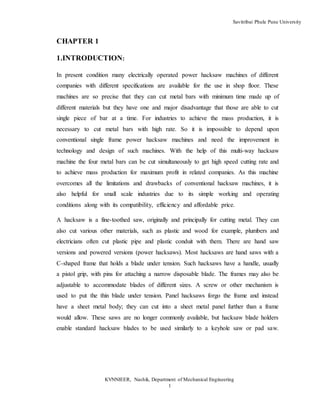
  • 8. Savitribai Phule Pune University KVNNIEER, Nashik, Department of Mechanical Engineering 8 Different Types Of Hacksaw Machine For Optimization 1. Model No. CE 1 Manufacture by :- Creative Engineers, Rajkot Cost of machine :- 45000/- Having following specification Table No.1.1 Specification of Model CE 1 Machine Particulars Cutting capacity Blade size (mm) Motor HP Cutting Stroke/min CE 1 75 mm 300/12 0.5 60-75 CE 1 machine having following features i. High speed machine for fast and bulk cutting ii. Higher accuracy iii. Less vibration
  • 9. Savitribai Phule Pune University KVNNIEER, Nashik, Department of Mechanical Engineering 9 Fig. No1.1. Hacksaw Machine Model No CE 1 2. Power Metal Hacksaw Machine Manufacture by :-Vishwacon Engineers Pvt Ltd, Ahemedabad Cost of machine :- 50000/- Machine Having following specification Table No. 1.2 Specification of Power Metal Hacksaw Machine Motor speed (rpm) Cutting capacity Blade size (mm) Motor HP Cutting Stroke/min 1440 45mm 300/12 1.5 80-85
  • 10. Savitribai Phule Pune University KVNNIEER, Nashik, Department of Mechanical Engineering 10 Fig. No.1.2Power Metal Hacksaw Machine 1.4 Hydraulic Hacksaw Machine Manufacture by :-Yash Machine Tool, Ahmedabad Cost of machine :- 43000/- Having following specification Table No. 1.3Specification of Hydraulic Hacksaw Machine Motor speed (rpm) Cutting capacity Blade size (mm) Motor HP Cutting Stroke/min 1440 60 400/32 1 80-85
  • 11. Savitribai Phule Pune University KVNNIEER, Nashik, Department of Mechanical Engineering 11 Fig No.1.3Hydraulic Hacksaw Machine 1.1 Problem Statement : The power hacksaw machines, which are operated by human operators as mentioned, have the demerit of unloading and loading the work-piece many times. In industries manufacturing pumps, these machines are used to cut the motor shafts to the required lengths. It will be difficult for the operator if he has been assigned to cut a huge quantity of motor shafts and he has to measure the lengths each time for cutting. Since humans are not as versatile as machines, there is a possibility that there may be inaccuracies. Besides, if there is a slight time delay in between every cycle of cutting a piece, the cumulative delay in time will be found to have a considerable magnitude, which might have been utilized properly if the proposed machine were in use there.To cut different metal bar pieces with high rate andaccuracy to minimize an idle time. 1.2Objectives : The most commonly used objective function is the specific cost.Walvekar and Lambert used geometric programming for the selection of machining variables. The optimum values of both cutting speed and feed rate were found out as a function of depth of cut
  • 12. Savitribai Phule Pune University KVNNIEER, Nashik, Department of Mechanical Engineering 12 in multi-pass Cutting operations .analyzed the problem of optimum cutting parameters selection by finding out the optimal cutting speed which satisfies the basic manufacturing criterion. We have optimize the hack saw machine model of C.E. 1 with it’s present specification and in lower of cost. And taking extra development in the present hack saw machine. 1.3 Scope : Four way hack saw machine is very effective for small scale industry because its manufacturing cost is very less. And it cut four work piece at one time in same power as compare to power hack saw, therefore the cutting cost are reduces therefore overall production cost is reduced. 1.4 Methodology : This project consists of single phase vertical electric motor rigidly placed at the center of metallic foundation provided. The shaft of motor rotates at 1440 rpm with the power 0.5 HP The circular disc is mounted on the shaft of motor with the help of key and key slot arrangement. The eccentric point on the plane of disc is provided such that the desired cutting stroke is achieved (around 4-5 inches). One end of each connecting rod is pivoted at this eccentric point by the use of suitable bearing. Another end of each rod is connected to the hacksaw blade fame with thehelp of universal joint to get vertical and horizontal Degree of Freedom of rotation for the proper cutting operation. The hacksaw frame slides on the guide ways provided. When motor is ON and disc starts rotating, due to the reciprocating motion of hacksaw frame the metal rod is cut which is firmly fixed in vise. The automatic feeding of coolant is provided to reduce heat generated due to friction which also avoids. 1.5 Organization of Dissertation We are conducting project development and its construction and fabrication workshop at our college also where will have possible it’s helpful for our project.
  • 13. Savitribai Phule Pune University KVNNIEER, Nashik, Department of Mechanical Engineering 13 PROCESS FLOW CHART Market Survey Of Different Type Of Hacksaw Machine Selecting The One Hacksaw Machine That To Be Optimized Preparation of The Designed Of Hacksaw Machine Selection Of Materials For Different Parts Of Hacksaw Machine Purchasing The Various Parts Of Machine Selection Of Manufacturing Process Assembling Of Multi-Way Hacksaw Machine Testing of Machine for preparation of Optimization process Calculating the Various Type Of Parameters Which Is Subjected To Optimization Process Chart No.1.5.1.Process Flow Chart
  • 14. Savitribai Phule Pune University KVNNIEER, Nashik, Department of Mechanical Engineering 14 CHAPTER 2 2.1 Literature Review : Prof.KshirsagarPrashant R., RathodHarayan J., RahatePrashant P., HalayePrashantP., SurveSahine design and theoretical analysis of multi way power hacksaw machine.There are many industrial applications where round bar or square bars are required to be operated on different machines to make machine components such as Shafts, Bolts, Screws etc. This needs more and more number of pieces to be cut for mass production of those components. To achieve this goal the Multi-way power hacksaw machine is developed. This paper proposes the model of multi-way hacksaw machine which is able to cut four pieces simultaneously without any jerk and minimum vibrations. The model implies conversion of rotary motion into the reciprocating motion for proper working of hacksaw. This model overcomes the limitations of conventional hacksaw machines which can cut single piece at a time. It is able to cut metal bars of different materials at same time and will be helpful in many industries due its compatibility, reliability and efficiency.[01] Prof. Nitinchandra R. Patel, Ravi Thakkar, MiteshkumarRathwa in his research paper “Material selection and testing of hacksaw blade based on mechanical properties” stated that the appropriate saw blade must be selected for better operation and fine cutting by selecting number of teeth per inch. There are four types of blades based on material namely High Carbon steel, Alloy Steel, Bi-metallic strip and High speed steel blades. Out of these four the best suitable for cutting hard materials like Mild steel bar and Aluminum is Bi-metallic blade on the basis of Properties of materials, Wear resistance and Cutting performance. Testing of different material blades like High Carbon Steel, Low Alloy Steel, Bi-metallic blade, High speed Steel blades for their hardness, Cutting time performance, Wear Resistance, Tensile Strength and performance under buckling. Experiment of Rockwell Hardness tester for getting Hardness Number on C-Scale for all different types of blades, so their relative hardness of teeth of different blade blades can be compared. For Cutting Performance test, Cutting of same diameter (25mm) job
  • 15. Savitribai Phule Pune University KVNNIEER, Nashik, Department of Mechanical Engineering 15 of different materials like Aluminum, Brass, Copper by all blades and their cutting time is noted and compared. For Wear Resistance ability, Profiles of blades-before and after cutting are developed with the help of profile projector.[02] D.V.Sabarinanda, V.Siddhartha, T.Mohanraj in their paper “Design and Fabrication of Automated Hacksaw Machine” (April 2014) gives an idea about the various components required for fabrication of the proposed model. These components will help to get smooth working condition and future automation of different mechanical actions as well as linkages. The objectives is to automate the conventional power hacksaw machine in order to achieved high productivity of work-pieces than the power hacksaw machine using microcontroller. The automated machine acquires two inputs from the user namely the number of pieces to be cut and the length of each piece that is required to be cut. The inputs are given by the user with the help of a keypad and an LCD display, which will help the user to verify the data given by him. The operator need not measure the length of the work-piece that is to be cut and to load and unload the work- piece from the chuck each time after a piece has been cut. After acquiring the two inputs from the user, the machine automatically feeds the given length of work-piece in to a chuck and starts to cut till the given number of work-pieces has been cut. The machine feeds the work-piece with the help of a conveyor, which is driven by a DC motor and an IR sensor ensures that the feeding stops when the specified length has been reached. A pneumatic cylinder is used for holding the work-piece when cutting operation is done. An AC motor is used to bring about the reciprocating motion required for cutting the work-pieces. There is a self-weight attached with the reciprocating mechanism to provide the necessary downward force required for penetration of hacksaw blade in to the work-piece. When a single piece has been cut, a limit switch will get triggered by the self-weight mechanism, which is sensed by the microcontroller to start the cyclic operation again provided if the specified number of work-pieces has not been cut.[03]
  • 16. Savitribai Phule Pune University KVNNIEER, Nashik, Department of Mechanical Engineering 16 R. Subash, K. Samuel Jayakaran, (2014), In this paper author has designed Pedal operated hacksaw machine which can be used for industrial applications and Household needs in which no specific input energy or power is needed. This project consists of a sprocket arrangement, the crank and slider mechanism, the chain drive. In the mechanism, chain drive is directly connected to the hacksaw for the processing of cutting the wooden blocks. The objective of the paper is using the conventional mechanical process which plays a vital role. The main aim is to reduce the human effort for machining various materials such as wooden blocks, steel, PVC etc.[04] Girish T.,Parameswaramurthy D.(2014), In this paper author has designed to development of conceptual model of water pumping and battery charging cross trainer which is user friendly, easy to do exercise, save & stores the energy of the users muscle efforts. When the human operates the lever and the pedal, the Centrifugal Pump is actuated and the water is pumped from ground sump to the tank. At the same time the attached dynamo (i.e., is mounted near the V-belt) operates and the mechanical energy is converted in to electrical energy, the generated electrical energy is stored in battery with the help of wires. The stored electrical energy is used when we are needed. [05] UmeshBokade, Zakiuddin Syed Kazi and Girish D Mehta, (2013), the author proposed the designed model which will convert the dirty/saline water into pure/ potable water using the renewable source of energy (i.e., Human power). The machine consists of a human-powered flywheel motor using a bicycle-drive mechanism with speed-increasing gearing and a flywheel, which drive the process unit though a spiral jaw clutch and torque increasing gearing. The operator puts energy into the flywheel at a convenient power level for about one minute. After enough energy is stored, pedaling is stopped and the energy in the flywheel is made available to the process unit.[06] DharwaChaitanyaKirtikumar designed and developed a multipurpose machine which does not require electricity for several operations like cutting, grinding etc. This is a human powered machine runs on chain drives mainly with human efforts. But if you wanted to operate this machine by electric power this machine can also does that. It has
  • 17. Savitribai Phule Pune University KVNNIEER, Nashik, Department of Mechanical Engineering 17 some special attachment so use both human power as well as electric power. The design is ideal for use in the developing world because it doesn’t require electricity and can be built using metal base, chain, pulley ,rubber belt, grinding wheel, saw, bearing, foot pedal (for operated by human) ,electric motor, chain socket. [07] S.G.Bahaley, Dr. A.U. Awate, S.V. Saharkar designed and fabricated a pedal powered multipurpose machine. It is a human powered machine which is developed for lifting the water to a height 10 meter and generates 14 Volt, 4 ampere of electricity in most effective way. Power required for pedaling is well below the capacity of an average healthy human being. The system is also useful for the work out purpose because pedaling will act as a health exercise and also doing a useful work.[08] Stephan Tambari, Dan Orawari Gloria, OrueneDiabi, Ayejan Victor designed and fabrication of pedal power hacksaw cutting machine. The aim of this work is to develop a modernized and less stressful operation for cutting woods metals and plastics material. It is very useful for cutting PVC materials and can be used widely in furniture making industries. This work also serve as an exercising machine for fitness while cutting it uses the principle of slider crank mechanism which converts the rotary motion of flywheel to the reciprocating motion of the hacksaw during its motion.The machine was tested and continued to be very efficient with an ideal mechanical Advantage of 0.5 (less than 1), velocity ratio of 0.65 (less than 1), a power output of 5.72KW and an efficiency of 76.9%, which makes it very adequate and capable for cutting.[09] Prof.Zoeb Khan, Mr.Sushil Dopkar Designed and fabrication of human power wood cutting machine.This is improved design of the human powered wood cutting machine which gives the less efforts of man and commonly used in rural areas where there is no power supply. The design ensures a smooth operation during the cutting process. The cutting force is provided by means of chain drive, gear assembly and other kinematic mechanism and all the parameter need to be optimized to get maximum cutting force. This machine is used for heavy duty wood cutting process for multiple operations like
  • 18. Savitribai Phule Pune University KVNNIEER, Nashik, Department of Mechanical Engineering 18 furniture, farm equipment’s, workshop and construction areas etc. It is light in weight and portable machine.[10] Avilasha B.G., Dr.Ramakrishna D.S. designed the measurement of load acting on machines and structures is important from many considerations. Accurate weighing of commodities, applying known load on specimens being tested for strength, safe operation of material handling equipment such as crane, determination of operating loads are some examples. When the load or forces are to be measured, a load cell is to be placed in the load path. Many times, it is not feasible to insert the load cell in the load path. In such cases, using the machine member themselves for measuring load will be advantageous. This dissertation work involves study Hack Saw machine where the load measurement is essential. Investigation is carried out to study the feasibility of using the member of the machine itself as load sensing member. The load measurement involves identification of critical component in the load path. Many times, it is not feasible to insert the load cell in the load path. In such cases, using the machine member themselves for measuring load will be advantageous. This dissertation work involves study Hack Saw machine where the load measurement is essential. Investigation is carried out to study the feasibility of using the member of the machine itself as load sensing member. The load measurement involves identification of critical component in the load path. While the process of load measurement is not straightforward in case where the known load is cannot be applied, inverse FEM is to be adopted for the case where applied load is not known. Once the critical component in the load path is identified, electrical resistance strain gauges are mounted in an appropriate fashion to get maximum output for an applied load. The dynamic strain was recorded using the LABVIEW software. The finite element analysis done for hacksaw machine with proper boundary conditions and the strain data are taken for series of loads and then these values are compared with the experimental strain value and the unknown load was estimated.[11]
  • 19. Savitribai Phule Pune University KVNNIEER, Nashik, Department of Mechanical Engineering 19 Umesh Bokade, Zakiuddin Syed Kazi and Girish D Mehta, (2013), the author proposed the designed model which will convert the dirty/saline water into pure/ potable water using the renewable source of energy (i.e., Human power). The machine consists of a human-powered flywheel motor using a bicycle-drive mechanism with speed-increasing gearing and a flywheel, which drive the process unit though a spiral jaw clutch and torque increasing gearing. The operator puts energy into the flywheel at a convenient power level for about one minute. After enough energy is stored, pedaling is stopped and the energy in the flywheel is made available to the process unit.[12] Linxu, WeinanBai, JingyuRu,Qiang Li designed and developed an automatically reciprocating pedal powered electricity generator (ARPPEG) in conjunction with the management and control over harvesting the kinetic energy, electricity generation, electric storage and the output of electricity. According to the operation testing results, this system has been proved to effective in power generation. In view of the simple structure and low costs of this system without territory and time limits, the application of ARPPEG designed by them could open a new path to saving the energy and helping build a new energy society.[13] Heinrich Arnold1 November 2001: Rather long re-investment cycles of about 15 years have created the notion that innovation in the machine tool industry happens incrementally. But looking at its recent history, the integration of digital controls technology and computers into machine tools have hit the industry in three waves of technology shocks. Most companies underestimated the impact of this new technology. This article gives an overview of the history of the machine tool industry since numerical controls were invented and introduced and analyzes the disruptive character of this new technology on the market. About 100 interviews were conducted with decision-makers and industry experts who witnessed the development of the industry over the last forty years. The study establishes a connection between radical technological change, industry structure, and competitive environment. It reveals a number of important occurrences and interrelations that have so far gone unnoticed.
  • 20. Savitribai Phule Pune University KVNNIEER, Nashik, Department of Mechanical Engineering 20 Recent trends in the machine tool technologies are surveyed from the view points of high speed and high performance machine tools, combined multifunctional machine tools, ultra precision machine tools and advanced and intelligent control technologies.[14] Frankfurt-am Main, 10 January 2011. : The crisis is over, but selling machinery remains a tough business. Machine tools nowadays have to be veritable “jack of all trades”, able to handle all kinds of materials, to manage without any process materials as far as possible, and be capable of adapting to new job profiles with maximized flexibility. Two highly respected experts on machining and forming from Dortmund and Chemnitz report on what’s in store for machine tool manufacturers and users.[15] PrashantH.Patil,SureshS.Patil designed and optimization weight of fixed jaw of rear vice of horizontal band saw machine using optimization.This paper is about Weight reduction of fix jaw of rear vice. Rear vice used for clamping work piece during cutting operation. It has two jaws Fix jaw and movable jaw. Movable jaw attached to hydraulic cylinder which applies force to hold work piece between these two jaw. Reduce weight of components help to minimize load on environmental resources .This efforts for reduction of weight by using topology optimization. fix jaws has been modeled using solid works First conducted analysis on existing jaws with calculating the forces acting on jaws in order to find out Max. Displacement and stress induced. These analyses were carried using Altair Hyperworks and solver used is optistuct. Again conducted topology optimization with applying manufacturing constrain like minimum member size and single type draw direction. Again prepare cad model based on topology result and carried analysis on optimized model. from the analyzed results, Displacement and stress are lower than existing model. From result it was found that current design is safe also save material and cost of component, Finally we reduced total weight by 12 % of current fix jaw model. Topology optimization analysis is carried out in Hyperworks which yielded in weight optimized.[16]
  • 21. Savitribai Phule Pune University KVNNIEER, Nashik, Department of Mechanical Engineering 21 Mohmad Saad Saleem,Mahmad Shadab Khan designed the effect of load on dry abrasive wear in blades of hand hacksaw.In this study, the abrasive wear is calculated in the High Carbon Steel (HCS) blades of Hand Hacksaw at different Loads. The wear is calculated by Mass Loss of blade before and after cutting the prepared specimen of Mild steel. The Wear is calculated for different specimen of blades at different Loads i.e. 5N,10N,15N and 20N with the help of the experimental Setup prepared. The result indicates that the wear in the blades increases with the increase in load.[17] H.G.Chothani,B.B.Kuchhadiya,J.R.Solanki designed the selection of material for material for hacksaw blade using AHP-PROMETHEE approach.In Technical Institute/Mechanical Workshop, Decision maker always faces the problem to select the perfect hacksaw blade material for students as well as trainee to reduce the failure rate of blade and avoid the accident. Numbers of methods are available for selection of an optimal material for an engineering design from among two or more alternative materials on the basis of two or more attributes. In this paper Preference Ranking Organization Methods for Enrichment Evaluations (PROMETHEE) and analytic hierarchy process (AHP) method have been applied to rank out the material of hacksaw blade among of five materials.[18] Padmanabham S. Chandrasekaran M. Srinivasa Raman V. design optimization of worm gear drive.Gears are used in almost all mechanical devices and do numerous essential jobs and important it provides a gear reduction. This is vital to ensure that even though there is enough power there is also enough torque. Gear box has to produce maximum power with minimum weight. In many real-life problems, objectives under consideration conflict with each other, and optimizing a particular solution with respect to a single objective can result in unacceptable results with respect to the other objectives. Multi-objective formulations are realistic models for many complex engineering optimization problems. A reasonable solution to a multi- objective problem is to investigate a set of solutions, each of which satisfies the objectives at an acceptable level without being dominated by any other solution. In
  • 22. Savitribai Phule Pune University KVNNIEER, Nashik, Department of Mechanical Engineering 22 this paper, Ant Colony Optimization was developed specifically for a Worm gear drive problem with multiple objectives.[19] Prof.Dr.Sarwar ,Dr.Haider J. Dr.Person M. designed Scientific evaluation of cutting- off process in Band sawing. In metal processing industries, bandsawing plays a key role in cutting off variety of raw materials as per to the customer required dimensions. The chip formation in bandsawing is a complex process owing to its distinctive relationship between edge geometry (edge radius: 5 µm - 15 µm) and the layer of material (5 µm - 50 µm) removed. This unique situation in bandsawing can lead to inefficient material removal with complex chip formation characteristics compared to a single point cutting tool. In this paper, scientific evaluation of the performance of bandsaw by full product and time compression simulation techniques has been discussed. Specific cutting energy parameter calculated based on cutting force and material removal data has been used to quantitatively measuring the efficiency of the metal cutting process or the machinability of a workpiece. The wear modes and mechanisms in bandsaw cutting edges have been discussed. The results presented in this paper will be of interest to the design engineers and bandsaw end users.[20] Mr. Parth B. Shah,Mr. ChandreshMotka, Mr. Krunal A. Shah designed a analysis and optimization of gearbox efficiency.The less efficiency of gear box of a machine tool is a serious problem as it increases maintenance cost and also affects the reputation of a firm. Hence its life has to be increased and should be made more reliable. The work to be done here is to find and rectify the causes of failure thereby improving the life of it. Also bearing failure should be reduced which is a cause of system failure. The alternative for the above problem is to design and optimization of a worm and worm gear box which reduced maintenance and improved reliability, lack of lubrication requirements, precise peak torque transmission, inherent overload protection, physically isolated input and output shafts, misalignment tolerance, and low acoustic noise and vibration etc. The parameters considered in the research are Lead Angle, Backlash and Bearing failure. [21]
  • 23. Savitribai Phule Pune University KVNNIEER, Nashik, Department of Mechanical Engineering 23 Girish T.,Parameswaramurthy D.(2014), In this paper author has designed to development of conceptual model of water pumping and battery charging cross trainer which is user friendly, easy to do exercise, save & stores the energy of the users muscle efforts. When the human operates the lever and the pedal, the Centrifugal Pump is actuated and the water is pumped from ground sump to the tank. At the same time the attached dynamo (i.e., is mounted near the V-belt) operates and the mechanical energy is converted in to electrical energy, the generated electrical energy is stored in battery with the help of wires. The stored electrical energy is used when we are needed. [22] R.D.Ankush, P.D.Darade designed and analysis of worm gear pair used in self locking system with development of manual clutch.In these systems when the driving torque is suddenly decreased due to power off or any mechanical failure at the input shaft of the system, then gears will be rotating either in the same direction driven by the system inertia, or in the opposite direction driven by the resistant output load due to gravity, spring load, etc. The latter condition is known as back driving. However, there are also solutions in gear transmission that prevent inertial motion or back driving using self- locking gears without any additional devices. Self-locking is the ability of gear system which constitute a drive which gives the input gear the freedom to rotate the output gear in either directions but the output gear locks with input when an outside torque attempts to rotate the output in either direction. Worm gear pair is also a self-locking gear pair but it is having very low efficiency around 40%, when made self-locking. In our project, self-locking property is obtained by using worm pair which is in mesh with each other. This system is simple in construction. The efficiency around 90% can be obtained as compared to 40% of conventional worm gear system.[23] RakeshAmbade,AmitSartabe,MeghrajArekar,PrajaktaGawali,designed and fabrication of human power multi purposemachine.This paper presents the concept of Human Powered Multi-Purpose Machine mainly carried out for production based industries. Industries are basically meant for Production of useful goods and services at low
  • 24. Savitribai Phule Pune University KVNNIEER, Nashik, Department of Mechanical Engineering 24 production cost, machinery cost and low inventory cost. Today in this world every task have been made quicker and fast due to technology advancement but this advancement also demands huge investments and expenditure, every industry desires to make high productivity rate maintaining the quality and standard of the product at low average cost. We have developed a conceptual model of a machine which would be capable of performing different operation simultaneously, and it should be economically efficient .This machine can be used in remote places where electricity is irregular or insufficient. It is designed as a portable one which can be used for cutting in various places. It can be used for operating on materials like thin metals,wood and p.v.c.The material can be cut without any external energy like fuel or current. Since machine uses no electric power and fuel, this is very cheap. Energy is the most vital aspect in the development of modern technological civilization. In the present work, a human powered multipurpose machine is developed which can perform three types of operations drilling, sawing and grinding. Power required for pedaling is well below the capacity of an average healthy human being. The system is also useful for the work out purpose because pedaling will act as a health exercise and also doing a useful work.[24] Faydor L. Litvin, Alessandro Nava, Qi Fan, and Alfonso Fuentes designed a New Geometry of Worm Face Gear Drives With Conical andCylindrical Worms: Generation, Simulation of Meshing,and Stress New geometry of face worm gear drives with conical and cylindrical worms is proposed. The generation ofthe face worm-gear is based on application of a tilted head-cutter (grinding tool) instead of application of ahob applied at present. The generation of a conjugated worm is based on application of a tilted head-cutter(grinding tool) as well. The bearing contact of the gear drive is localized and is oriented longitudinally. Apredesigned parabolic function of transmission errors for reduction of noise and vibration is provided. Thestress analysis of the gear drive is pertbrmed using a three-dimensional finite element analysis. Thecontacting model is automatically generated. The developed theory is illustrated with numerical examples.[25]
  • 25. Savitribai Phule Pune University KVNNIEER, Nashik, Department of Mechanical Engineering 25 YonghongChen,YanChen,WenjunLuo,Guanghui Zhang has Development and Classification of Worm Drive.Worm drive is the key machine element, and it is widely used to transmit motion and power at the shaft angle of 90°. In this paper, the development history of the worm drive is reviewed, the characteristics and applications of each worm drive are introduced. A worm drive systematic classification table is proposed based on the viewpoint of generating body shape, generating surface shape, tooth position and meshing area. Moreover, there exist universality and regularity on the geometry and transmission performance of each type, each series and each form in this systematic classification table. Based on the development of worm drive and the characteristics of industrial development in recent years, the development trends and research hotspots of worm drive are presented. This study is expected to guide researchers to reform the existing worm drive and invent the new worm drive.[26] R. Subash, K. Samuel Jayakaran, (2014), In this paper author has designed Pedal operated hacksaw machine which can be used for industrial applications and Household needs in which no specific input energy or power is needed. This project consists of a sprocket arrangement, the crank and slider mechanism, the chain drive. In the mechanism, chain drive is directly connected to the hacksaw for the processing of cutting the wooden blocks. The objective of the paper is using the conventional mechanical process which plays a vital role. The main aim is to reduce the human effort for machining various materials such as wooden blocks, steel, PVC etc.[27] David Gordon Wilson, (1986), According to the author, a person can generate four timer more power (1/4 horsepower (hp)) by pedaling than by hand-cranking. At the rate of1/4hp, continuous pedaling is for can done only short periods, about 10 minutes. However, pedaling at half this power (1/8 hp) can be sustained for around 60 minutes. Pedal power enables a person to drive devices at the same rate as that achieved by hand-cranking, but with far less effort and fatigue. Pedal power also lets one drive devices at a faster rate than before (e.g. winnower), or operate devices that require too
  • 26. Savitribai Phule Pune University KVNNIEER, Nashik, Department of Mechanical Engineering 26 much power for hand-cranking (e.g. thresher). The main use of pedal power today is still for bicycling, least in the high-power at range (75 watts and above of mechanical power). In the lower-power range there are a number of uses of pedal power-for agriculture, construction, water pumping, and electrical generation-that seem to be potentially advantageous, at least when electrical or internal-combustion engine power is unavailable or very expensive.[28] Vivek Kumar Chauhan, Faheem Khan, Chandra Kumar Johi designed and development of pedal power hacksaw. In this paper an effort has been made to design and developed model of Pedal Powered Hacksaw. The pedal powered hacksaw is a device which is used for cutting wood, plastic and metals. The basic principles of power driven hacksaw is Slider Crank Mechanism which is an inversion of four bar chain mechanism. In this mechanism, the connecting rod is directly connected to the hacksaw for the processing of cutting the wooden blocks. The hacksaw move to and fro motion when the pedal is powered, so as the rotating disc rotates. The main aim of this project is to reduce the human effort for machining various materials.[29] S.K.Deepak designed the cutting speed and feed rate optimization for minimizing production time of turning process. Optimum selection of cutting conditions importantly contribute to the increase of productivity by minimization of production time and the associated costs, therefore utmost attention is paid to this problem in this contribution. Time is the most important parameter in any operation and all the manufacturing firms aim at producing a product in minimum time to reach the customer quickly and enhance the customer satisfaction. This can be achieved by using optimization techniques. The success of an optimization technique does not lie in its complexity but the time in which it provides a solution to the manufacturing firms. In this research paper, a geometric programming based approach to optimize the production time of the turning process within in some operating constraints is proposed. It involves mathematical modeling for production time of turning process, which is expressed as a function of the cutting parameters which include the cutting
  • 27. Savitribai Phule Pune University KVNNIEER, Nashik, Department of Mechanical Engineering 27 speed and feed rate. Then, the developed mathematical model was optimized with in some operating constraints like the maximum cutting speed, maximum feed rate, power constraint and the surface roughness constraint. The results of the model reveal that the proposed method provides a systematic and efficient technique to obtain the optimal cutting parameters that will minimize the production time of turning process. Thus, it is possible to optimize the production time of turning process effectively by geometric programming. The approach is suitable for fast determination of optimum cutting parameters during machining, where there is not enough time for deep analysis.[30] SurajM.Satmohankar,AbhilashH.Khante,VishalV.Janbandhu,KartikD.Chafekar,Jitendr apachabhai designed an automatic cutting machine. In this paper we are concerned about Belt conveyor system not only used in mining industries but also used in cement industries, power plant, food industries, production industries etc. So it is essential instrument for in house material transportation today. The paper presents the review of belt conveyor design modification and latest technologies or working used in different applications to reduce failures, maintenance cost and equipment related fatal accidents occurs during operation. In today’s geopolitical climate, ensuring the protection of secure facilities or key locations against resourceful and determined intruders is of paramount importance to the defense of a national border as well as industries of national importance. The greatest threat to national security is “Terrorism” and it cannot be defeated by conventional military force alone. In critical border areas, regular forces or even satellites cannot monitor. These intruding terrorists as the area monitored is quite large and quite complex. To assist the army and security forces operating in these areas, smart dust like micro-sensors with wireless interfaces could be utilized to study and monitor these environments from a certain distance for military purposes. The spiral bevel gear (SBG) is a key component of the power Transmission of intersection axes. Since the mathematical model of the SBG is a basis for stress and thermal analysis, the optimization of machine-tool settings, frictional contact analysis in lubricated condition, and advanced manufacturing technology,
  • 28. Savitribai Phule Pune University KVNNIEER, Nashik, Department of Mechanical Engineering 28 research on designing and manufacturing of SBGs based on mathematical models of SBG has long been a topic of considerable interest in the field of mechanical transmission.[31] Dr. ManojDevare designed a Mathematical Modeling and Interface Design for Gear Error Testing.This work gives two major contributions that is software user interface design, and the automation of the gear testing data. This work is having the real time data handling, which is received from the sensors and handling the pulses converted into the digital formats of the data. This system is not only providing the effectiveinput screen design but also the meaningful output reports. Generation of the output reports and graphs requires the principals and standard graphics theory based algorithms for plotting the graphs for the tracing the rotational motion of the gear. The linear and circular graphs have been drawn to indicate the different errors such as backlash and pitch errors. It is necessary to have the knowledge of the interfacing of the sensors to the hardware unit, in the field of mechatronics. This work is simple case study and mathematical model for graph plotting from the rotational motion to the linear graphs for different scales and proportions. This piece of work also shares the experiences while automation of the gear error discovery techniques and interfacing of the hardware data. [32] Ion Gavrila designed a tooth's tensions analysis of face worm gears with cylindrical pinion development of FEA.The subject of this research project is extensive analysis of tension, stress and strains of face worm gear tooth, with special attention given to the influence of surface roughness. Gear teeth working surfaces are subjected to repeated rolling and sliding contacts. For operating conditions common for power transmission applications, the loads are sufficient to cause eventual fatigue of the surface. The surface roughness of a gear is one of the most influential factors that defines the quality of surface how determine indirectly fatigue capability of gear, and so this subject is of particular interest and importance to the field of gear design. This
  • 29. Savitribai Phule Pune University KVNNIEER, Nashik, Department of Mechanical Engineering 29 research project sought to provide analytical tools to further the understanding of the causal relationship of gear surface roughness to surface fatigue. [33] Muminovic N.,Repcic N. designed Calculation Of Parameters In The Engagement Field Of Worm Gears.In order to optimally design the worm gears in terms of the temperature (the heat) limit, it is necessary to have the knowledge of the operation losses. In addition to the applied lubricant that influences the efficiency degree, the geometry of gearing also plays a significant role by the conditions necessary for the hydrodynamic lubrication. The work presented here provides a mathematical model for description of the engagement geometry and solving the problem of worm gears lubrication (calculation of loss of power). Based on the presented mathematical model, the own computer program has been developed that enables rapid analysis of parameters in the engagement field (the engagement surface, the sliding velocities, the summary velocities, and the equivalent radius of curvature in the contact points of the engagement field.. [34] Amit S. Shelake, Prof. N. S. Hanamapure designed aBending Stress Analysis of Worm Wheel of Winch Machine Gearbox Using 3D Photoelasticity& FE AnalysisThe ‘Advance Engineering’, Kolhapur uses worm & worm wheel in gear box of Winch machine for lifting sand buckets of approximate weight of 250 kg & at height 25 feet. The motor used to drive the worm has power of 2 Hp& speed of 1440 rpm. The speed reduction is 60:1. In working condition of gear box, worm wheel fails due to load coming on the teeth. The crack is initiated at central thickness of tooth. Hence the tooth breaks at the central thickness. The failure occurs once within operational period of about 15 days. So the industry has to replace the worm wheel which is not cost effective. Calculation of stresses of worm wheel at tooth thickness is a 3D problem. This paper represents the analysis of stresses using theoretical, experimental and FE analysis. Experimentally obtained results are verified with the finite element analysis (FEA) results. Also proper solution is provided.. [35]
  • 30. Savitribai Phule Pune University KVNNIEER, Nashik, Department of Mechanical Engineering 30 DariuszOstrowski ,TadeuszMarciniak designed a Worm Gear's Kinematic Accuracy Measurement Methods.The paper discusses measurements conditions of worm gear kinematic accuracy, including construction and operation principles of the kinematic deviation measuring stand. There are presented two methods of measuring gear kinematic accuracy: direct method consisting in comparison of rotation angle of gear and worm wheel in the full rangeof rotation relatively to tooth elements; indirect method – consisting in measurementof worm wheel’s circuital tooth scale. In addition, notions of kinematic deviation andkinematic diversion of worm gear were defined. Paper presents as well examples of kinematic errors results of A80 gear depending on adopted measuring step – a number ofmeasurements per one full worm rotation. The result of research was determination of aminimal measuring step per full worm rotation L1 = 300, wider resolution did not causesignificant changes of measurement result.[36] Ahmad RazlanYusoff, Mohamed Reza Zalani Mohamed Suffian and MohdYusofTaib designed and optimization techniques for chatter surpressionin machining.Chatter produces a poor surface finish and high tool wear and can even damage machine tools as a result of the regenerative effect, the loss of the contact effect and the mode coupling effect. The early and latest researches are to suppress chatter by either passive or active methods by applying absorber, damping, varied speed and alternatives. In this paper, it can be observed that the optimization focuses on spindle design, tool path, cutting process and variable pitch for chatter suppression. There are various algorithms which can be applied in optimization of machining problems; however, Differential Evolution (DE) is the appropriate candidate that can solve time consuming, local optimal and more robust as compared to Genetic Algorithm (GA), although it has widely applications, and Sequential Quadratic Programming (SQP) as a famous conventional algorithm can be employed for chatter suppression.[37] Gun-HeeKim ,Jeong-Won Lee , and Tae Seo designed Durability Characteristics Analysis of Plastic Worm Wheel with Glass Fiber Reinforced Polyamide. Plastic
  • 31. Savitribai Phule Pune University KVNNIEER, Nashik, Department of Mechanical Engineering 31 worm wheel is widely used in the vehicle manufacturing field because it is favorable for weight lightening, vibration and noise reduction, as well as corrosion resistance. However, it is very difficult for general plastics to secure the mechanical properties that are required for vehicle gears. If the plastic resin is reinforced by glass fiber in the fabrication process of plastic worm wheel, it is possible to achieve the mechanical properties of metallic material levels. In this study, the mechanical characteristic analysis of the glass-reinforced plastic worm wheel, according to the contents of glass fiber, is performed by analytic and experimental methods. In the case of the glass fiber-reinforced resin, the orientation and contents of glass fibers can influence the mechanical properties. For the characteristic prediction of plastic worm wheel, computer-aided engineering (CAE) analysis processes such as structural and injection molding analysis were executed with the polyamide resin reinforcement glass fiber (25 wt %, 50 wt %). The injection mold for fabricating the prototype plastic worm wheel was designed and made to reflect the CAE analysis results. Finally, the durability of prototype plastic worm wheel fabricated by the injection molding process was evaluated by the experimental method and the characteristics according to the glass fiber contents.. [38] Sreejth K.,DanieDavis,FarishK.A.,George Johnson designed experimental investigation of pedal power hacksaw.The objective of this paper was to design, fabricates and experimentally investigate the working of Pedal Driven Hacksaw(PDH). PDH is working on Slider Crank Mechanism. The experiment was done using PDH and plywood work pieces. The main parts of PDH are hack saw, reciprocating rod welded to the pedal of a bicycle, flywheel, sprocket and chain drive. The hack saw is connected with the reciprocating rod. By pedaling the bicycle the reciprocating rod moves to and fro, the hack saw will be moving with the rod. The plywood to be cut is placed under the hack saw. Thus the plywood can be cut without any external energy like fuel or current. Since this uses no electric power and fuel, this is very cheap and best. The performance of the PDH was compared with Hand Hacksaw at different rpm. The results indicate that the PDH had given better, accurate
  • 32. Savitribai Phule Pune University KVNNIEER, Nashik, Department of Mechanical Engineering 32 and faster cuts when compared with hand hacksaw at different rpm. PDH reduces the effort of cutting plywood to a great extent. When compared to the Power Saw the PDH requires only manual power thereby reducing the utility bill considerably. Experimental result shows that cutting depth of about 17 mm can be obtained in one cycle of strokes for around100rpm.[39]
  • 33. Savitribai Phule Pune University KVNNIEER, Nashik, Department of Mechanical Engineering 33 CHAPTER 3 DESIGN OF ELEMENTS OF MACHINE 3.1 Designing Of Machine Element In Mechanical design the components are categories in two parts. 1. Design parts 2. Parts to be purchased. For design parts detail design is done and dimensions thus obtained are compared to next highest dimension which are readily available in market this simplifies the assembly as well as post production servicing work. The various tolerances on work pieces are specified in the manufacturing drawings. The process charts are prepared & passed on to the manufacturing stage .The parts are to be purchased directly are specified &selected from standard catalogues. 3.1.1System Design:- In system design we mainly concentrate on the following parameter 3.1.1.1 System Selection Based On Physical Constraints:- While selecting any m/c it must be checked whether it is going to be used in large scale or small scale industry in our case it is to be used in small scale industry so space is a major constrain .The system is to be very compact. The mechanical design has direct norms with the system design hence the foremost job is to control the physical parameters. 3.1.1.2 Arrangement Of Various Components:- Keeping into view the space restriction the components should be laid such that their easy removal or servicing is possible moreover every component should be easily seen & none should be hidden every possible space is utilized in component arrangement.
  • 34. Savitribai Phule Pune University KVNNIEER, Nashik, Department of Mechanical Engineering 34 3.1.1.3 Components Of System:- As already stated system should be compact enough so that it can be accommodated at a corner of a room. All the moving parts should be well closed & compact A compact system gives a better look & structure. Following are some example of this section:  Design of machine height  Energy expenditure in hand operation  Lighting condition of machine 3.1.1.4 Chances Of Failure:- The losses incurred by owner in case of failure of a component are important criteria of design. Factor of safety while doing the mechanical design is kept high so that there are less chances of failure. Periodic maintenance is required to keep the m/c trouble free 3.1.1.5 Servicing Facility:- The layout of components should be such that easy servicing is possible especially those components which required frequent servicing can be easily dismantled. 3.1.1.6 Height Of Machine From Ground:- Fore ease and comfort of operator the height of machine should be properly decided so that he may not get tired during operation .The m/c should be slightly higher than that the level also enough clearance be provided from ground for cleaning purpose. 3.1.1.7 Weight Of Machine:- The total wt. of machine depends upon the selection of material components as well as dimension of components. A higher weighted m/c is difficult for transportation & in case of major break down it becomes difficult to repair.
  • 35. Savitribai Phule Pune University KVNNIEER, Nashik, Department of Mechanical Engineering 35 3.2 Selection Of Machine Components 3.2.1 Motor Selection Thus selecting a motor of the following specifications Three phase AC motor Power = 0.5=0.37K watt Speed= 1440 rpm Motor is a three phase AC motor, Power 0.37 kw, Speed is continuously 1440 rpm. The speed of motor is variated by means of an electronic speed variator. Motor is accommodator motor i.e., the current to motor is supplied to motor by means of carbon brushes. The power input to motor is varied by changing the current supply to these brushes by the electronic speed variator; thereby the speed is also is changes. Motor is foot mounted and is bolted to the motor base plate welded to the base frame of the indexer table. Motor Torque P= 2 П N T 60 T = 60 x P 2 П x 1440 T = 2.47 x 10⁻³ N.m = 2.47 N.mm 3.3 Design Of Gear Drive 3.3.1 Design of Worm And Worm Wheel A worm gear is used when a large speed reduction ratio is required between crossed axis shafts which do not intersect. A basic helical gear can be used but the power which
  • 36. Savitribai Phule Pune University KVNNIEER, Nashik, Department of Mechanical Engineering 36 can be transmitted is low. A worm drive consists of a large diameter worm wheel with a worm screw meshing with teeth on the periphery of the worm wheel. The worm is similar to a screw and the worm wheel is similar to a section of a nut. As the worm is rotated the worm wheel is caused to rotate due to the screw like action of the worm. The size of the worm gear set is generally based on the center distance between the worm and the worm wheel. If the worm gears are machined basically as crossed helical gears the result is a highly stress point contactgear. Worm gears are used for transmitting power between two non-parallel, non-intersecting shafts. High gear ratios of 200:1 can be got. The worm is made of case hardened steel 14C6 whereas the worm wheel is made gun metal. Table No.3.3.1.Number Of Starts On Worm Speed Ratio No. of starts on worm 30 & above 1 15-30 2 7-15 4 Below 7 6 For the single start worm gear Designation selected from standard worm gear pair is given by Zw/Zg/q/m = 1/38/11.2/2 Where, Zw= No. of start on worm Zg= No. of teeth on worm gear q = Diametric quotient
  • 37. Savitribai Phule Pune University KVNNIEER, Nashik, Department of Mechanical Engineering 37 m= module Dimensions of worm and worm gear dw= m x q = 2 x 11.2 = 22.4 mm dg= m x Zg= 2 x 38 = 76 mm Pa =xm = x 2 =6.283 mm L=PaxZw = 6.283 x 1 = 6.283 mm Now, Lead angle of worm tanλ = L/x dw =6.283/  x 22.4 λ = 5.10210 Lengh of worm is calculated by Lw = x m [4.5 + (Zg/50) = x 2 [4.5 + (38/50) = 33.04 mm To Calculate Worm Wheel shaft Torque T design = 0.4 X Reduction Ratio Of Wormgear Box T design = 0.4 X 38 =15.2 N-m a. The geometry of a worm is similar to that of a power screw. Rotation of the worm simulates a linearly advancing involute rack,
  • 38. Savitribai Phule Pune University KVNNIEER, Nashik, Department of Mechanical Engineering 38 b. The geometry of a worm gear is similar to that of a helical gear, except that the teeth are curved to envelop the worm. c. Enveloping the gear gives a greater area of contact but requires extremely precise mounting. Fig.No.3.3.1.Worm And Worm Gear Drive 1. As with a spur or helical gear, the pitch diameter of a worm gear is related to its circular pitch and number of teeth Z. 2. When the angle is 90 0 between the nonintersecting shafts, the worm lead angle (λ) is equal to the gear helix angle. 3. The pitch diameter of a worm is not a function of its number of threads, Z1 4. This means that the velocity ratio of a worm gear set is determined by the ratio of gear teeth to worm threads; it is not equal to the ratio of gear and worm diameters. ω Z1 = ω Z2
  • 39. Savitribai Phule Pune University KVNNIEER, Nashik, Department of Mechanical Engineering 39 5. Worm gears usually have at least 24 teeth, and the number of gear teeth plus worm threads should be more than 40: Z1 + Z2> 40 6.A worm of any pitch diameter can be made with any number of threads and any axial pitch. 7. For maximum power transmitting capacity, the pitch diameter of the worm should 8. Integral worms cut directly on the shaft can, of course, have a smaller diameter than that of shell worms, which are made separately. 9. Shell worms are bored to slip over the shaft and are driven by splines, key, or pin. Strength considerations seldom permit a shell worm to have a pitch diameter less than d1 = 2.4p + 1.1 11. The face width of the gear should not exceed half the worm outside diameter. b ≤ 0.5 da1 Fig. 3.3.2 Nomenclature Of A Single Enveloping Worm Gear
  • 40. Savitribai Phule Pune University KVNNIEER, Nashik, Department of Mechanical Engineering 40 Friction coefficient Cast Iron and Phosphor Bronze x = 1.15 Cast Iron and Cast Iron x= 1.33 Quenched Steel and Aluminum Alloy. x = 1.33 Table 3.3.2 Worm Lead Angle For Various Pressure Angles Lead Angle λ 0-150 15-300 30-400 40-450 Normal Pressure Angle Φn 14.50 200 250 300 Components of forces Acting on worm :- Tangential force acting on the worm and worm gear (fw) = Pi Vw But, Vw = πdwnw 60x1000 = π x 22.4x 1440 60 x 1000 Vw = 1.6889...m/s
  • 41. Savitribai Phule Pune University KVNNIEER, Nashik, Department of Mechanical Engineering 41 Fig.No.3.3.3 Forces Analysis a) The tangential, axial, and radial force components acting on a worm and gear are illustrated in the fig. b) For the usual 900 shaft angle, the worm tangential force is equal to the gear axial force and vice versa. F1t = F2a F2t = F1a c) The worm and gear radial or separating forces are also equal, F1r = F2r If the power and speed of either the input or output are known, the tangential force acting on this member can be found from equation 1000WF= V 1. In the Fig. No. 3.3.3 the driving member is a clockwise-rotating right hand worm.
  • 42. Savitribai Phule Pune University KVNNIEER, Nashik, Department of Mechanical Engineering 42 2. The force directions shown can readily be visualized by thinking of the worm as a right hand screw being turned so as to pull the “nut” (worm gear tooth) towards the “screw head”. 3. Force directions for other combinations of worm hand and direction of rotation can be similarly visualized. Thrust Force Analysis. The thrust force direction for various worm and worm wheel drive conditions are shown in below figure. (a)
  • 43. Savitribai Phule Pune University KVNNIEER, Nashik, Department of Mechanical Engineering 43 (b) Fig.No.3.3.4 (a) And (b) Worm Gears Thrust Force Analysis The thread angle λ of a screw thread corresponds to the pressure angle φn of the worm. We can apply the force, efficiency, and self-locking equations of power screw directly to a worm and gear set. These equations are derived below with reference to the worm and gear geometry. Figs.a and b shows in detail the forces acting on the gear. Components of the normal tooth force are shown solid. Components of the friction force are shown in below figure.
  • 44. Savitribai Phule Pune University KVNNIEER, Nashik, Department of Mechanical Engineering 44 Fig.No.3.3.5 Forces on the worm gear tooth Friction Analysis. The coefficient of friction, f, varies widely depending on variables such as the gear materials, lubricant, temperature, surface finishes, accuracy of mounting, and sliding velocity. The typical coefficient of friction of well lubricated worm gears is given in Figure.
  • 45. Savitribai Phule Pune University KVNNIEER, Nashik, Department of Mechanical Engineering 45 Chart.No.3.3.1Characteristic Chart Table No.3.3.3 Selection Of Lead Angle And Normal Pressure Angle Lead angle in λ in degree Pressure angle Φnin degree Addendum hain mm Dedendumhrin mm 0-15 14.5 0.3683 p 0.3683 p 15-30 20 0.3683 p 0.3683 p 30-35 25 0.2865 p 0.331 p 35-40 25 0.2546 p 0.2947 p 40-45 30 0.2228 p 0.2578 p Table No.3.3.4 selection of helix angle Helix angle ψ in ° Efficiency η in % Helix angle ψ in ° Efficiency η in % Helix angle ψ in ° Efficiency η in % 1.0 25.2 7.5 71.2 20.0 86.0 2.5 46.8 10.0 76.8 25.0 88.0 5.0 62.6 15.0 82.7 30.0 89.2
  • 46. Savitribai Phule Pune University KVNNIEER, Nashik, Department of Mechanical Engineering 46 Table No.3.3.5 selection of gear ratio and gear pair Power (P), P = 0.5 HP =0.5 × 746 = 373 watts or 0.373 Kw Torque for single start : T=2.73 × 10⁻³ N-mm =2.73 N-m Fwt= 373/1.6889 =220.85 N Tangential force (Fwt) =220.85 N Axial force acting on worm (Fwa) =Fwt/(tanΦv +λ) Where ‚ Φv= Virtual friction angle =tan-l µv Centre Distance ‘a’ mm Gear Ratio ‘G’ Worm Gear Pair Zw/Zg/q/m 7.25 4/29/10.6/2.5 9.5 4/38/11.2/2 14.5 2/29/10.6/2.5 50 19 2/28/11.2/2 29 1/29/10.6/2.5 38 1/38/11.2/2 62 1/62/17.92/1.25
  • 47. Savitribai Phule Pune University KVNNIEER, Nashik, Department of Mechanical Engineering 47 µv=0.05 & Φv= 2.9564 (Fwa) = 220.85 Tan(2.9564+5.1021) = 1559.87 N 3) Radial force cutting on worm : (Fw)r= (Fw )t= tan Φv sinλ [ tanλ/ (tanΦv+tanλ)] = 220.85 × tan 14.5 sin5.1021 [ tan5.1021 / (tan14.5+tan5.1021)] = 406.89 N (Fw)r = 406.89 N Now , Components of force on the acting on the worm gear , (Fg)t = (Fw)a = 1559.87 N (Fg)a=(Fw)t= 220.85 N (Fg)r=(Fw)r= 406.89 N Efficiency of worm and worm gear pair : η = tanλ tan(Φv+λ)
  • 48. Savitribai Phule Pune University KVNNIEER, Nashik, Department of Mechanical Engineering 48 = tan5.1021 tan(2.9564+5.1021) η =63.06% & Power lost in friction ; Pf=(1-η )Pi =(1-0.6306)×0.373 Pf = 0.137 kw 3.4 DESIGN OF SHAFT A shaft is the component of a mechanical device that transmits rotational motion and power.It is integral to any mechanical system in which power is transmitted from a prime mover, such as an electric motor or an engine, to other rotating parts of the system. Because of the simultaneousoccurrence of torsional shear and normal stresses due to bending, thestress analysis of a shaft virtuallyalways involves the use of a combined stress approach.The recommended approach for shaftdesign and analysis is the distortionenergy theory of failure. Shaft is a common and important machine element. It is a rotating member, in general, has a circular cross-section and is used to transmit power. The shaft may be hollow or solid. The shaft is supported on bearings and it rotates a set of gears or pulleys for the purpose of power transmission. The shaft is generally acted upon by bending moment, torsion and axial force. Design of shaft primarily involves in determining stresses at critical point in the shaft that is arising due to aforementioned loading. Other two similar forms of a shaft are axle and spindle.
  • 49. Savitribai Phule Pune University KVNNIEER, Nashik, Department of Mechanical Engineering 49 Vertical shear stresses anddirect normal stresses due toaxial loads may also occur. On very short shafts or onportions of shafts where nobending or torsion occurs, suchstresses may be dominant. 3.4.1 Types of shaft : 1) Transmission shaft :- A shaft which is used to transmit the power between the sources and machine absorbing the power is called transmission shaft. 2) Machine Shaft : Its short rotating shaft which form an internal part of the machine it self. Standard Sizes Of Shafts : Typical sizes of solid shaft that are available in the market are, Up to 25 mm 0.5 mm increments 25 to 50 mm 1.0 mm increments 50 to 100 mm 2.0 mm increments 100 to 200 mm 5.0 mm increments Materialused ForShafts For transmission shaft are made of i. Low carbon steel – 20c8,25c8,30c8 ii. Medium carbon steel – 35c8, 40c8,45c8, 50c4 iii. High carbon steel- 60c4, 65c6 iv. Alloy steel – 35Mn6M03, 40Cr 4Mo2,35Ni5Cr2 v. The ferrous, non-ferrous materials and non metals are used as shaft material depending on the application. Some of the common ferrous materials used for shaft are discussed below. 1) Hot-rolled plain carbon steel : These materials are least expensive. Since it is hot rolled, scaling is always present on the surface and machining is required to make the surface smooth.
  • 50. Savitribai Phule Pune University KVNNIEER, Nashik, Department of Mechanical Engineering 50 2) Alloy steels : Alloy steel as one can understand is a mixture of various elements with the parent steel to improve certain physical properties. To retain the total advantage of alloying materials one requires heat treatment of the machine components after it has been manufactured. Nickel, chromium and vanadium are some of the common alloying materials. However, alloy steel is expensive. These materials are used for relatively severe service conditions. When the situation demands great strength then alloy steels are used. They have fewer tendencies to crack, warp or distort in heat treatment. Residual stresses are also less compared to CS(Carbon Steel). DesignConsiderations For Shaft : For the design of shaft following two methods are adopted, DesignBasedOn Strength :- In this method, design is carried out so that stress at any location of the shaft should not exceed the material yield stress. However, no consideration for shaft deflection and shaft twist is included. DesignBasedOn Stiffness :- Basic idea of design in such case depends on the allowable deflection and twist of the shaft.In certain cases the shaft needs to be wear resistant, and then more attention has to be paid to make the surface of the shaft to be wear resistant. Procedure for Designof Shaft 1. Determine the rotational speed ofthe shaft. 2. Determine the power or the torqueto be transmitted by the shaft. 3. Determine the design of thepower-transmitting components orother devices that will be mountedon the shaft, and specify therequired location of each device. 4. Specify the location of bearings tosupport the shaft. Normally onlytwo bearings are used to support ashaft.
  • 51. Savitribai Phule Pune University KVNNIEER, Nashik, Department of Mechanical Engineering 51 The stress at any point on the shaft depends on the nature of load acting on it. The stresses which may be present are as follows. Basic stress equations : Bending stress , Bending stress(σb) = 32 M/ π d0 3 (1-k4) Where, M : Bending moment at the point of interest do : Outer diameter of the shaft k : Ratio of inner to outer diameters of the shaft ( k = 0 for a solid shaft because inner diameter is zero ) Axial Stress : σa= 4 α E/ π d0 2 (1-k2) Where, F: Axial force (tensile or compressive) α: Column-action factor(= 1.0 for tensile load) The term α has been introduced in the equation. This is known as column action factor. What is a column action factor? This arises due the phenomenon of buckling of long slender members which are acted upon by axial compressive loads. Stress Due To Torsion. τxy= 16 T / π d0 3 (1-k4) Where, T : Torque on the shaft τxy : Shear stress due to torsion
  • 52. Savitribai Phule Pune University KVNNIEER, Nashik, Department of Mechanical Engineering 52 3.4.2 Material Selection: - Table No.3.4.2.1 Material Strength and Properties DESIGNATION ULTIMATE TENSILE STRENGTH N/mm2 YEILD STRENGTH N/mm2 EN 24 800 680 Properties For Shaft Material :- 1. It should be high static strength . 2. It should be ductile. 3. It should be high resilience. 4. It should be have good machinability. 5. It should be high fatigue strength. 3.4.3ASME CODE FOR DESIGN OF SHAFT Since the loads on most shafts in connected machinery are not constant, it is necessary to make proper allowance for the harmful effects of load fluctuations According to ASME code permissible values of shear stress may be calculated form various relations. τ = 0.18 x 800 τ = 144 N/mm2 OR
  • 53. Savitribai Phule Pune University KVNNIEER, Nashik, Department of Mechanical Engineering 53 fsmax = 0.3 fyt =0.3 x 680 =204 N/mm Considering minimum of the above values; fsmax = 144 N/mm2 Shaft is provided with key way; this will reduce its strength. Hence reducing above value of allowable stress by 25% fsmax = 108 N/mm2 Allowable shear stress as per ASME code (without keyway) For commercial steel shafting is 55 N/mm2 Allowable shear stress as per ASME code (with keyway) i) For commertial steel shafting τall=0.75 x 55 = 41 N/mm2 ii) If steel purchased under specification τall=0.75 x 0.3 Syt or 0.75 x 0.188 Sut select which is minimum value. This is the allowable value of shear stress that can be induced in the shaft material for safe operation. 3.4.4 Check For Torsional Shear Failure OfShaft Assuming minimum section diameter on input shaft = 14.3 mm as the worm wheel is to be mounted on shaft and minimum bore size that can be machined with dimensional tolerances is 14.3 mm
  • 54. Savitribai Phule Pune University KVNNIEER, Nashik, Department of Mechanical Engineering 54 d = 14.3 mm Td = /16 x fsact x d3 fsact = 16 x Td  x d 3 = 16 x 15.2 x 10 3  x (16) 3 fs act = 26.9 N/mm2 As fs act <fs all input shaft is safe under torsional load Material of Shaft EN24 Sult = 800 N/mm2 Sylt = 680N/mm2 fs all = 108 N/mm2 power= 373w shear stress τ =41 N Diameter of shaft=18 mm (by measuring) τmax= 16 Te π d3 41= 16 Te π x183 Te= 46.94x 10 3
  • 55. Savitribai Phule Pune University KVNNIEER, Nashik, Department of Mechanical Engineering 55 Table No.3.4.2 Selection of values of Kb and Kt Nature of loading Kb Kt 1)Stationary shaft  Gradual load  Sudden load 1 1.5-2.0 1 1.5-2.0 2)Rotating Shafts  Gradual load  Sudden with minor shock  Sudden load with heavy shock 1.5 1.5 to 2.0 2.0-3.0 1 1.0-1.5 1.5-3.0 Kb=1.5 &Kt= 1.2 but , 𝑇𝑒 = √( 𝐾𝑏. 𝑚)2 + ( 𝐾𝑡. 𝑇)2 2.20 x 109= (1.5M)2+(1.2T)2 2.20 x 109=2.25M2+1.44T2 P= 2π N T 60 x 1000 373= 2 x π x1440xT 60 T = 2473.53 N-mm 2.20 x 109= 2.25 M2 + 1.44(2473.53)2 M=31206.76 N-mm
  • 56. Savitribai Phule Pune University KVNNIEER, Nashik, Department of Mechanical Engineering 56 Where, T= Torque of shaft M= Moment of shaft 3.4.5 Design Of Bearing (Selection of Ball Bearing) In selection ofball bearing the main governing factor is the system design of the drive i.e.; the size of the ball bearing is of major importance; hence we shall first select an appropriate ball bearing first select an appropriate ball bearing first taking into consideration convenience of mounting the planetary pins and then we shall check for the actual life of ball bearing. The purpose of a ball bearing is to reduce rotational friction and support radial andaxial loads. It achieves this by using at least two races to contain the balls and transmit the loads through the balls. In most applications, one race is stationary and the other is attached to the rotating assembly (e.g., a hub or shaft). As one of the bearing races rotates it causes the balls to rotate as well. Because the balls are rolling they have a much lower coefficient of friction than if two flat surfaces were sliding against each other Ball Bearing Selection P = XFr + Yfa. Where ; P=Equivalent dynamic load ,(N) X=Radial load constant Fr= Radial load(H) Y = Axial load contact Fa = Axial load (N)
  • 57. Savitribai Phule Pune University KVNNIEER, Nashik, Department of Mechanical Engineering 57 In our case; Radial load FR= Pt = 15200/33 =460.6 N. P= 460.6 N L= (C/p) p L = 60 n L h 106 AS required dynamic of bearing is less than the rated dynamic capacity of bearing ; Bearing is safe. Selection Of Hacksaw Blade : A hacksaw is a fine-tooth saw with a blade under tension in a frame, used for cutting materials such as plastics, metals etc. The principle of metal cutting is working principle for hacksaw blade cutting operation. For cutting operation to be done the hacksaw blade should be of harder material than material to be cut. The well known power hacksaw machine is powered by electric motor. So the saw or saw blade is important component in consideration for high rates of cutting to be done. Different Types of Saw blades: Following are the types of blades which are generally used material cutting. 1. High Carbon Steel 2. Bi-Metallic Steel 3. High Speed Steel 4. Low Alloy Steel
  • 58. Savitribai Phule Pune University KVNNIEER, Nashik, Department of Mechanical Engineering 58 Table No.3.4.5.1 Types Of Blades Used For Material Cutting Wear Resistance Test Of Blade : Table No.3.4.5.2 Wear Resistance Of The Blade From the Table, Following conclusions are made on account of wear resistance 1.High Speed Steel has less wear working with Mild Steel. 2.Low Alloy Steel has good wear resistance working with Brass. 3.High Carbon Steel when working with Aluminum . Material HSS Bi-Metallic Steel Low Alloy Steel High Carbon Steel Hardness Best Better Good Fair Mild Steel Aluminum Brass High Speed Steel Best Fair Good Bi-Metallic Steel Better Good Fair Low Alloy Steel Fair Better Best High Carbon Steel Good best Better
  • 59. Savitribai Phule Pune University KVNNIEER, Nashik, Department of Mechanical Engineering 59 CHAPTER 4 CONSTRUCTION AND DEVOLOPMENT IN MACHINE 4.1 The Basic Components Of Multiway Hack Saw Machine Are: 4.1.1.Motor (1440RPM) Motor is a standard component 50 watt power, speed 0 to 6000variable speed. Motor carries the motor pulley connected to the input worm shaft pulley by means of acoupling. An electric motor is an electrical machine that converts electrical energy into mechanical energy. The reverse of this would be the conversion of mechanical energy into electrical energy and is done by an electric generator. In certain applications, such as in the transportation industry with traction motors, electric motors can operate in both motoring and generating or braking modes to also produce electrical energy from mechanical energy. Motor having 1440 rpm which give its best performance with as per load comes on it. It having best capacity to handle any how conditions to achieve its good performance. There are no. of models are available in market for different speed and its load performance, but achieving best performance we gives best importance on the such motor which gives to us its best performance. Fig.No.4.1.1.1 Motor
  • 60. Savitribai Phule Pune University KVNNIEER, Nashik, Department of Mechanical Engineering 60 4.1.2.Coupling Motor shaft is connected to the input worm shaft by means of ajow coupling of L70. A coupling is a device used to connect two shafts together at their ends for the purpose of transmitting power. Couplings do not normally allow disconnection of shafts during operation, however there are torque limiting couplings which can slip or disconnect when some torque limit is exceeded. Fig No.4.1.1.2. Jaw Coupling The primary purpose of couplings is to join two pieces of rotating equipment while permitting some degree of misalignment or end movement or both. By careful selection, installation and maintenance of couplings, substantial savings can be made in reduced maintenance costs and downtime. The rubber insert is designed to absorb shock loading and does not allow for any metal on metal contact. We stock both the Spider Elements as well as the Wrap Element Kits. We stock a range of jaw couplings in a variety of pre-bored and keyed sizes. The Jaw Coupling is recognized across a large range of industries. The Jaw Coupling is highly resilient, it does not require any lubrication and can work in environments contaminated with oil, dirt, sand, moisture and grease. A jaw coupling is a type of general purpose power transmission coupling that also can be used in motion control (servo) applications. It is designed to transmit torque (by connecting two shafts) while damping system vibrations and accommodating misalignment, which protects other components from damage. Jaw couplings are
  • 61. Savitribai Phule Pune University KVNNIEER, Nashik, Department of Mechanical Engineering 61 composed of three parts: two metallic hubs and an elastomer insert called an element, but commonly referred to as a "spider". The three parts press fit together with a jaw from each hub fitted alternately with the lobes of the spider. Jaw coupling torque is transmitted through the elastomer lobes in compression. The elastomer of the spider can be made in different materials and hardness, which allows the user to customize the coupling to best serve their application. Considerations for elastomer selection include ability to dampen vibration, ability to handle misalignment, operational temperature range, speed of equipment, and chemical conditions. Jaw couplings are considered "fail-safe" because, should the elastomer fail or wear away, the jaw coupling hub teeth will mate, much like teeth on two gears, and continue to transmit torque. This may or may not be desirable to the user depending on the application. Jaw couplings elastomers are wearing elements that do need to be inspected and replaced. Jaw coupling elastomers often have signature wear patterns, and failures can often be root caused based on the condition of the elastomer and hubs. Common failure causes include. 4.1.3 Worm And Worm Wheel : Worm and worm wheel arrangement is used as the reduction gear box arrangement. Worm is 1.5 module single start right hand worm whereas the worm wheel is 1.5 module 38 teeth gear. The worm shaft is held in ball bearing 6004 zz in bearing housing whereas the worm wheel is held on the main spline spindle.Aworm drive is a gear arrangement in which a worm (which is a gear in the form of a screw) meshes with a worm gear (which is similar in appearance to a spur gear). The two elements are also called the worm screw and worm wheel. The terminology is often confused by imprecise use of the term worm gear to refer to the worm, the worm gear, or the worm drive as a unit. Like other gear arrangements, a worm drive can reduce rotational speedor transmit higher torque. The image shows a section of a gear box with a worm
  • 62. Savitribai Phule Pune University KVNNIEER, Nashik, Department of Mechanical Engineering 62 gear driven by a worm. A worm is an example of a screw, one of the six simple machines. Fig.No.4.1.1.3 Worm and Worm Gear 4.1.4.Main Spindle : Main spline spindle is held in ball bearing 6205zz in gear box housing. ON main spindle mound the rotating plate on which supporting rod is mounted. spindle speed 1440 rpm by rotating with motor. its couple to gear box by using coupling .its able to transmit power entire system. 4.1.5.Drive Spindle : Spindle is fitted in housing by means of two ball bearings of 6204zz housed inside it is bolted to the boom. 4.1.6.HackSaw : The four hack saw frames are used in the machine. That is made up of High carbon steel.
  • 63. Savitribai Phule Pune University KVNNIEER, Nashik, Department of Mechanical Engineering 63 Fig No.4.1.1.6.Hacksaw A hacksaw is a fine-tooth saw with a blade under tension in a frame, used for cutting materials such as metal. Hand held hacksaws consist of a metal frame with a handle, and pins for attaching a narrow disposable blade. A screw or other mechanism is used to put the thin blade under tension. A power hacksaw (or electric hacksaw) is a type of hacksaw that is powered by electric motor. Most power hacksaws are stationary machines but some portable models do exist. Stationary models usually have a mechanism to lift up the saw blade on the return stroke and some have a coolant pump to prevent the saw blade from overheating. 4.1.7.Bearings A bearing is a machine element that constrains relative motion to only the desired motion, and reduces friction between moving parts.. Three types of bearings are used in the machine. One is 6200z, 62004zz, 6205zz. When kept floating, can confirm to the axis of the job during the translation motion, thereby ensuring the concentricity and co-axiality of the machined hole.
  • 64. Savitribai Phule Pune University KVNNIEER, Nashik, Department of Mechanical Engineering 64 Fig.4.1.1.7 Bearing 4.1.8.Vice For work piece holding we are used four baby vice. That hold the work piece up to the 50mm width. The vice is rigid construction. It has two jaws, one jaw remains fixed and the other is adjusted according to the size of the material to be cut. It’s able to fixed the rod to be cut and give constant holding for material to be cut. For holding purpose there are four vices are used and they sustain the rods for holding and it gives the constant Fig 4.1.1.8. Vice
  • 65. Savitribai Phule Pune University KVNNIEER, Nashik, Department of Mechanical Engineering 65 4.2 Constructional Diagram OfMultiway Hacksaw Machine (a)
  • 66. Savitribai Phule Pune University KVNNIEER, Nashik, Department of Mechanical Engineering 66 (b) Fig.No..4.2.2 Constructional Diagram of Multiway Hacksaw Machine
  • 67. Savitribai Phule Pune University KVNNIEER, Nashik, Department of Mechanical Engineering 67 4.3 Assembly of Machine Parts 4.3.1 Working of Hacksaw Machine : As the 3 phase AC supply is given to electric motor which couple to worm and worm type gear box through coupling. Motor having 1440 rpm and to achieve optimum speed gear box is provided.When the motor is starting it rotate the shaft of gear box with it. In this gear box speed reduction is carried out. The shaft of gearbox is connected to the circular plate through the crank. The crank rotates into the circular motion.There are four connecting rods are connected to the circular plate which give the rotation of 90° for every cutting stroke. Through connecting rod four hack saw cutters are connected at the end. When rotation of plate is done it moves blades for cutting and return stroke. And due this the cutting of metal is done.Every rotation of plate gives two cutting strokes and two return strokes. Which helps to reduce working time of operation.
  • 68. Savitribai Phule Pune University KVNNIEER, Nashik, Department of Mechanical Engineering 68 CHAPTER 5 EXPERIMENTAION 5.1 Cutting Performance Of Hacksaw Cutter (Cutting Time) We have performed cutting operations of these four blades on three different materials and the cutting action was Followed In Sequence Which Are As Follows: 1. Aluminum 2.Brass 3. Mild steel We have taken cutting time for same diameter jobs of above materials so we can find about the relative cuttingperformance. Here 25 mm Diameter of work piece is taken for being cut , this 25 mm round cross section is commonfor all different work pieces to be cut. Also we have taken profiles of blades on Profile Projector before and aftercutting of each material for all blades so that relative amount of wear can be determined. 5.2 Cutting performance High carbon steel blade is mainly used to cut the brass material as time for cutting of Brass material by Highcarbon steel blade is the least. So, the materials like brass, copper, bronze etc. are efficiently cut with highcarbon steel as far as time is concerned. For ferrous materials it takes lot of time to cut.Alloy steel blades are used to cut the non- ferrous materials like brass, aluminium etc. as they take lower time. for cutting of non-ferrous materials. Bi-metallic blades are the best to cut the ferrous materials like mild steel etc. as far as the cutting time isconcerned. Also for non-ferrous materials it gives good performance. HSS blades cut both ferrous as well as non-ferrous materials with minimum cutting time. 5.3 Wear test The high carbon steel experiences minimum wear on tooth for cutting the aluminium, gun metal etc. The brass material and other non-ferrous materials can be cut with alloy steel and high carbon steel for theminimum amount of wear. For cutting ferrous materials like mild steel, HSS as well as Bi-metallic blades experience lower wear whereasalloy steel blades experience highest wear for cutting ferrous
  • 69. Savitribai Phule Pune University KVNNIEER, Nashik, Department of Mechanical Engineering 69 materials.So, for cutting ferrous materials HSS and Bi-metallic blades are best in wear consideration also for cuttingnon-ferrous materials either high carbon steel or alloy steel is good as far as the wear is concerned. 5.4 Metal Cutting Rate For Hacksaw Machine Metal cutting is given by volume of metal cut with respective time. Forvarious materials cutting rate is given below. Table No.5.4.1 Material Cutting Rate For Various Material Material Cutting Rate ( mm/min) Cast iron 8 Alluminium 15 Steel 12
  • 70. Savitribai Phule Pune University KVNNIEER, Nashik, Department of Mechanical Engineering 70 CHAPTER 6 RESULTS Multi-way Hacksaw Machine Manufacture by :- KVNNIEER , NASHIK Cost of machine :- 20000/- Having following specification Table No.6.1 Result of Hack Saw Machine Particulars Cutting capacity Blade size (mm) Motor HP Cutting Stroke/min Multi-way Hacksaw Machine 40 mm 300/12 0.5 60-75 Multi-way Hacksaw Machine having following observations. 1.High speed machine for fast and bulk cutting. 2.Higher accuracy. 3.Less vibration. 4.Increasing production rate of cutting. 5.Less time required for production. 6.Labour cost reduced.