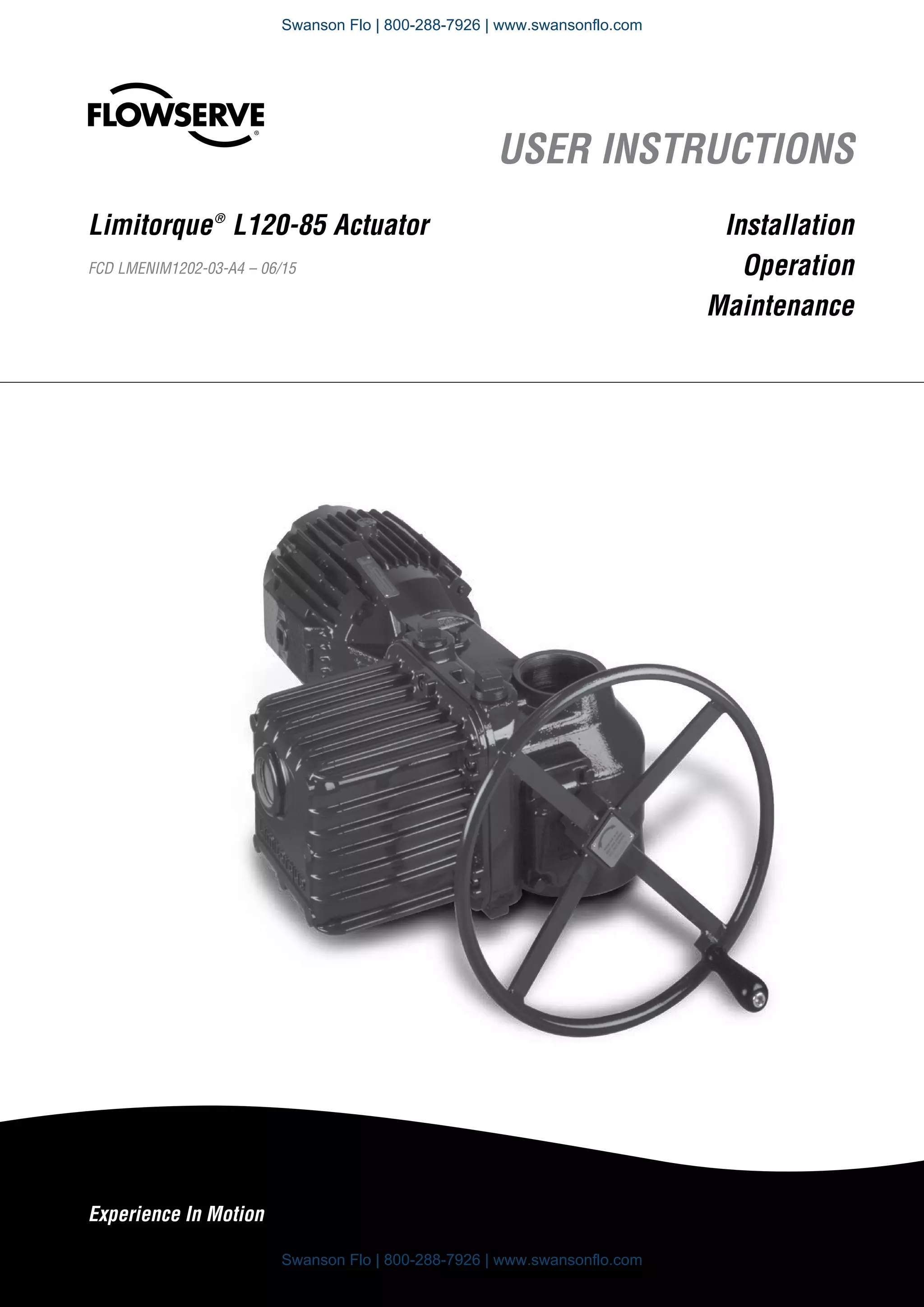
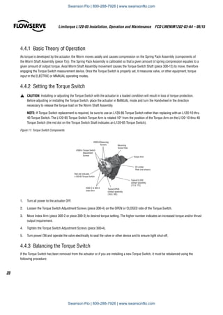
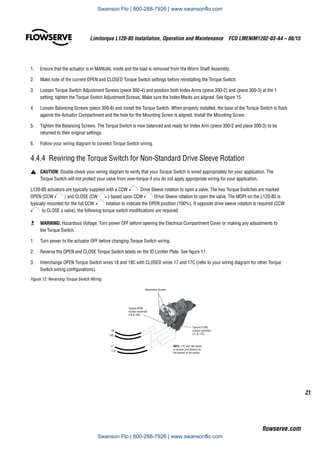
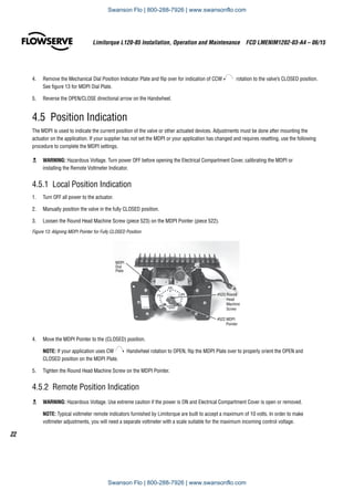
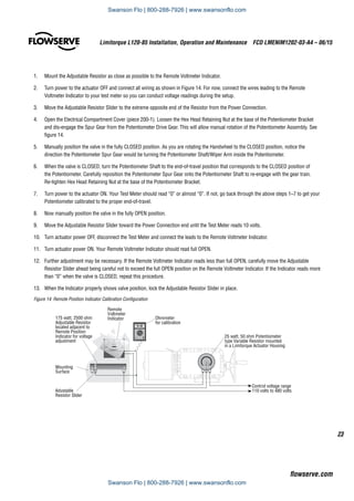
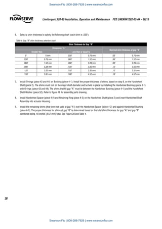
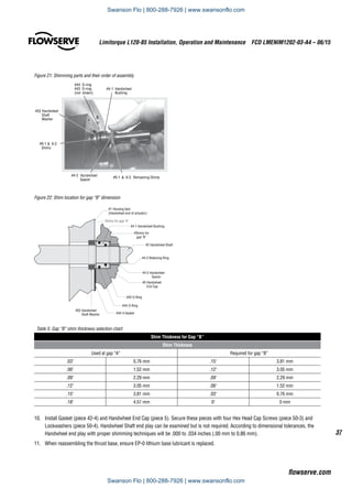
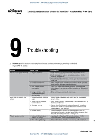
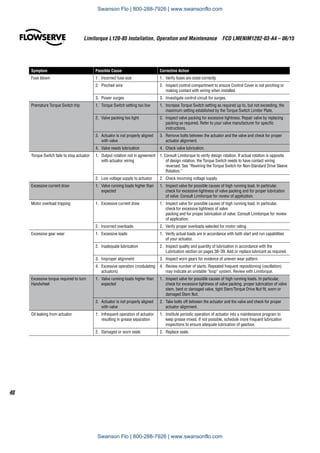
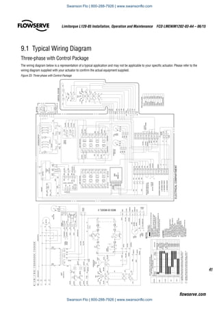
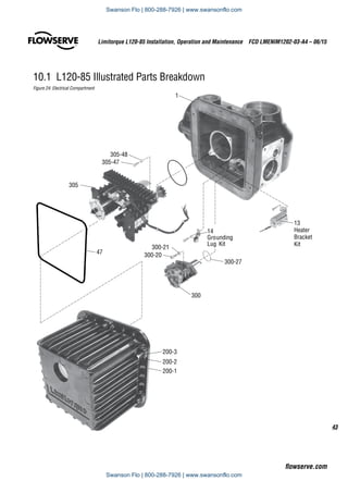
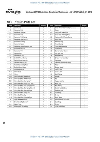
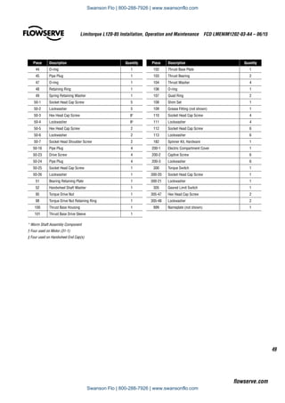
SlideShare a Scribd company logo
1 of 52
Download to read offline
Experience In Motion
USER INSTRUCTIONS
Installation
Operation
Maintenance
Limitorque®
L120-85 Actuator
FCD LMENIM1202-03-A4 – 06/15
Swanson Flo | 800-288-7926 | www.swansonflo.com
Limitorque L120-85 Installation, Operation and Maintenance  FCD LMENIM1202-03-A4 – 06/15
2
1	Introduction	 4
1.1	Purpose	 4
1.2	 User Safety 	 4
2	 Initial Inspection and Storage Instructions	 5
2.1	 Inspection and Recording	 5
2.2	 Short-Term Storage	 5
2.3	 Product Identification	 6
2.4	 Product Description	 7
2.5	 Product Features	 7
3	 Actuator Weight	 8
4	 Installation Instructions	 9
4.1	 Actuator Mounting	 9
4.1.1	 Torque Only Applications (Drive 1) 	 10
4.1.2	 Torque and Thrust Applications (Drive 2) 	 10
4.1.3	 Mounting Bolts	 11
4.1.4	 Stem Cover for Rising Stem Applications	 11
4.2	 Verifying Motor Rotation Direction	 13
4.2.1	 Initial Electrical Connections	 13
4.2.2	 Motor rotation (phasing) and OPEN/CLOSE
pushbutton operation.	 14
4.2.3	 Three-Phase Motor	 14
4.2.4	 DC Motor	 15
4.3	 Limit Switch Settings	 15
4.3.1	 Basic Theory of Operation	 16
4.3.2	Adjustment—General	 17
4.3.3	 Setting the OPEN Limit Switch	 17
4.3.4	 Setting the CLOSE Limit Switch	 19
4.4	 Torque Switch Setting and Wiring	 20
4.4.1	 Basic Theory of Operation	 20
4.4.2	 Setting the Torque Switch	 20
4.4.3	 Balancing the Torque Switch	 21
4.4.4	 Rewiring the Torque Switch
for Non-Standard Drive Sleeve Rotation	 21
4.5	 Position Indication	 21
4.5.1	 Local Position Indication	 21
4.5.2	 Remote Position Indication	 23
4.5.3	 Setting the Potentiometer	 24
5	Operation	 26
5.1	 Description of Motor Operation	 26
5.2	 Description of Manual Operation	 26
5.3	 Electrical Start-up Procedure	 27
6	Maintenance	 28
6.1	Lubrication	 28
6.1.1	 Initial Inspection	 28
6.1.2	Frequency	 28
6.1.3	 Routine Inspection	 28
6.1.4	 Factory Lubricants	 29
6.1.5	 Minimum Lubricant Qualities Required	 29
7	Disassembly	 30
7.1	 Removal From Valve	 30
7.2	 Open Electrical Compartment and Disconnect Motor	 30
7.3	 Remove Control Wiring	 31
7.4	 Remove Limit and Torque Switch	 31
7.5	 Remove Motor Assembly	 31
7.6	 Remove Handwheel	 31
7.7	 Remove Handwheel Shaft Assembly	 31
7.8	 Remove Declutch Lever Assembly	 32
7.9	 Remove Clutch Assembly	 32
7.10	 Remove Clutch Pinion Assembly	 32
7.11	 Remove Worm Shaft Assembly	 32
7.12	 Remove and Disassemble Thrust Base	 33
7.13	 Remove Drive Sleeve	 33
8	 Assembly	 34
8.1	 Handwheel Shaft Assembly and Shimming	 34
8.2	 Verifying Handwheel Operation	 38
8.3	 Thrust Base Assembly and Shimming	 38
9	Troubleshooting	 39
9.1	 Typical Wiring Diagram	 41
Three-phase with Control Package	 37
10	 How to Order Parts	 42
10.1	 L120-85 Illustrated Parts Breakdown	 43
10.2	 L120-85 Parts List	 48
11	 Regulatory Information	 50
Contents
Swanson Flo | 800-288-7926 | www.swansonflo.com
3
Limitorque L120-85 Installation, Operation and Maintenance  FCD LMENIM1202-03-A4 – 06/15
flowserve.com
Figures
Figure 1: Limitorque L120-85 Actuator	 7
Figure 2: L120-85 Torque Drive Nut and Retaining Ring Details	 10
Figure 3: Thrust Base removal from an L120-85	 10
Figure 4: L120-85 Torque Drive Nut orientation (Drive 1)	 12
Figure 5: L120-85 Thrust Base Assembly orientation (Drive 2)	 12
Figure 6: Electrical Compartment and Conduit Pipe Plug openings	14
Figure 7: Grounding Lug location	 14
Figure 8: Limit Switch Rotor development	 15
Figure 9: L120-85 Limit Switch Components	 17
Figure 10: Limit Switch OPEN/CLOSED Rotor Cam orientation	 18
Figure 11: Torque Switch Components	 20
Figure 12: Reversing Torque Switch wiring	 21
Figure 13: Aligning MDPI Pointer for Fully CLOSED Position	 21
Figure 14: Remote Position Indicator Calibration Configuration	 24
Figure 15: Potentiometer Calibration configuration	 24
Figure 16: Loosening Potentiometer Assembly	 25
Figure 17: Removing Clutch Pinion Assembly	 32
Figure 18: Key components affected by Handwheel shimming	 34
Figure 19: Cut-away view of L120-85 actuator
with Clutch Latch positioned on face of Clutch Bearing	 35
Figure 20: Gap between Housing face and Handwheel Bushing 		
shown as dimension “A”	 35
Figure 21: Shimming parts and their order of assembly	 37
Figure 22: Shim location for gap “B” dimension/	 37
Figure 23 Three-phase with Control Package	 41
Figure 24: Electrical Compartment	 43
Figure 25: Motor and Motor Drive Components	 44
Figure 26: Handwheel Shaft and Associated Components	 45
Figure 27: Drive Sleeve Group	 46
Figure 28: Thrust Base Group	 47
Tables
Table 1: L120-85 Approximate Weight Chart	 8
Table 2: Torque Drive Nut: Maximum Allowable
Bore and Key Sizes	 10
Table 3: L120-85 Actuator/Mounting Base Tap Size	 13
Table 4: Gap “A” shim thickness selection chart	 36
Table 5: Gap “B” shim thickness selection chart	 37
Swanson Flo | 800-288-7926 | www.swansonflo.com
1	Introduction	
1.1 Purpose
This Installation and Maintenance Manual explains how to install and maintain the L120-85 actuator.
Information is provided for installation, disassembly, reassembly, lubrication, and parts selection.
c	 WARNING: Read this installation and maintenance manual carefully and completely before storing,
installing, operating or troubleshooting your Flowserve Limitorque actuator. Be aware of electrical
hazards within the actuator and high-pressure hazards at the attached valve or other device when
installing or performing maintenance on your L120-85 actuator.
1.2  User Safety
Safety notices in this manual detail precautions the user must take to reduce the risk of personal injury and
damage to the equipment. The user must read and be familiar with these instructions before attempting
installation, operation, or maintenance. Work should be performed by a qualified tradesman who is familiar
with the operation and maintenance of electric actuators. Failure to observe these precautions could result in
serious bodily injury, damage to the equipment, voiding of the warranty, or operational difficulty.
Safety notices are presented in this manual in three forms:
c 	 WARNING: Refers to personal safety. Alerts the user to potential danger. Failure to follow warning
notices could result in personal injury or death.
a	 CAUTION: Directs the user’s attention to general precautions that, if not followed, could result in
personal injury and/or equipment damage.
NOTE: Highlights information critical to the user’s understanding of the actuator’s installation and
operation.
Limitorque L120-85 Installation, Operation and Maintenance  FCD LMENIM1202-03-A4 – 06/15
4
Swanson Flo | 800-288-7926 | www.swansonflo.com
2	Initial Inspection and 						
			Storage Instructions
2.1  Inspection and Recording
Upon receipt of the actuator, several steps should be initially followed to ensure condition of equipment and
to establish proper record keeping.
1.	 Carefully remove the actuator from the shipping carton or skid. Thoroughly examine for any physical
damage which may have occurred during shipment. If you note any damage, immediately report the
damage to the transport company.
2.	 A nameplate with important information is attached to each actuator. Record this information 		
for future reference.
2.2 Short-Term Storage (less than one year)
Actuators are not weatherproof until properly installed on the valve or prepared for storage.
Store actuators in a clean, dry, protected warehouse away from excessive vibration and rapid temperature
changes. If the actuators must be stored outside, they must be stored off the ground, high enough to prevent
them from being immersed in water or buried by snow.
1.	 Position the actuator in storage with motor and switch compartment horizontal.
2.	 Connect the internal heaters (if supplied) or place desiccant in the switch compartment.
3.	 Replace all plastic caps or plugs with taped or doped pipe plugs and ensure that all covers are tight.
4.	 If the actuator is mounted on a valve and the stem protrudes from the actuator, a suitable stem cover
must be provided.
5
Limitorque L120-85 Installation, Operation and Maintenance  FCD LMENIM1202-03-A4 – 06/15
flowserve.com
Swanson Flo | 800-288-7926 | www.swansonflo.com
2.3  Product Identification
The actuator nameplate is located on the back of the actuator, opposite the limit switch compartment.
The nameplate contains the following information:
•	 Product name
•	 Point of Manufacture
•	 Order Number
•	 Serial Number
•	 Customer Tagging
•	 Certification Information
The motor nameplate is located on the motor. The nameplate contains the following information:
•	 ID Number
•	 Run Torque
•	 RPM
•	 Full Load Amps
•	 Insulation Class
•	 Horsepower
•	 Number of Phases
•	 Motor Code
•	 Connection Diagram
•	 Start Torque
•	 Enclosure Type
•	 Volts
•	 Locked Rotor Amps
•	 Duty Rating
•	 Service Factor
•	 Frequency
•	 Ambient Temperature
Limitorque L120-85 Installation, Operation and Maintenance  FCD LMENIM1202-03-A4 – 06/15
6
Swanson Flo | 800-288-7926 | www.swansonflo.com
Figure 1: Limitorque L120-85 Actuator
Thrust
Base
Handwheel
Electrical
Compartment
Cover
Conduit
Openings
(plugged; two additional openings
are supplied on the bottom of the
Electrical Compartment)
Housing
Declutch
Lever
Motor
Position
Indication
Window
2.4  Product Description
Your L120-85 actuator controls the opening and closing travel of valves or other actuated devices. OPEN and CLOSED limits of travel are
controlled by limit switches, and output torque is controlled by the Torque Switches. As a result, all valves and other actuated devices are
protected from potential damage from overload, improper seating and foreign obstructions.
Limitorque actuators may be mounted on any appropriately sized valve in almost any position or location.
Microprocessor-based controls and monitoring devices are also available for L120 actuators. Contact your local Limitorque distributor or
Limitorque sales office for further information.
2.5  Product Features
•	 Up to 850 ft-lb/1156 Nm torque capacity.
•	 Up to 45,000 lb./20250 kg thrust capacity.
•	 Up to 3.25/76 mm threaded stem capacity.
•	 Up to 2.75/70 mm bore capacity.
•	 Torque Only (Drive 1) or Torque and Thrust (Drive 2) actuators, with removable ductile iron thrust base assembly.
•	 Cast iron gear housing.
•	 All power gearing supported on anti-friction bearings.
•	 All gearing is alloy, heat-treated steel or bronze.
•	 Speed range of 24-192 RPM (60 Hz), 20-160 RPM (50 Hz).
•	 Declutch force independent of load on valve stem.
•	 Self-locking gearing available.
7
Limitorque L120-85 Installation, Operation and Maintenance  FCD LMENIM1202-03-A4 – 06/15
flowserve.com
Swanson Flo | 800-288-7926 | www.swansonflo.com
3	Actuator Weight
The following table is an L120-85 representative weight chart. It provides the weight of several components
that may be incorporated into a typical package. Use the chart as a guideline to estimate the weight of your
particular actuator package.
Table 1: L120-85 Approximate Weight Chart
Components lb. kg
L120-85 with 40 ft-lb 1700 RPM Motor (Torque only) 275 125
With Minimum Integral Control
Package and Compartment
315 143
Thrust Base Assembly (Drive 2)1
70 32
1
Add to weights shown above for basic actuator or basic actuator with integral control package.
Limitorque L120-85 Installation, Operation and Maintenance  FCD LMENIM1202-03-A4 – 06/15
8
Swanson Flo | 800-288-7926 | www.swansonflo.com
4	Installation Instructions
c	 WARNING: Read this Installation and Maintenance Manual carefully and completely before
attempting to store, install, operate or troubleshoot your Limitorque valve actuator. Be aware of
electrical hazards within the actuator and high pressure hazards of the attached valve or other
actuated device when installing or performing maintenance on your L120-85 actuator.
NOTE: If your actuator incorporates a rising stem application, it may be shipped with a plastic cap over
the Drive Sleeve Housing. If so, in order to store without possible corrosion occurring, install a pipe plug
or protective stem cover to protect the Drive Sleeve Housing.
NOTE: Failure to comply with recommended storage procedures could cause the warranty to be voided.
For long-term storage procedures, consult the Limitorque Customer Service Department.
4.1  Actuator Mounting
Your L120-85 is designed to perform actuation for torque only applications (drive 1) or for torque and thrust
applications (drive 2). If you are using a torque only configuration, before installing on the valve or other actu-
ated device, you will need to verify that the Torque Drive Nut (piece 95) is properly bored and keyed to fit your
valve stem. If you are using a torque and thrust configuration, you will need to verify that the Thrust Base
Drive Sleeve (piece 101) is properly threaded to fit your threaded valve stem. Use the following procedures to
check for proper fit of the Torque Drive Nut or the Thrust Base Drive Sleeve.
9
Limitorque L120-85 Installation, Operation and Maintenance  FCD LMENIM1202-03-A4 – 06/15
flowserve.com
Swanson Flo | 800-288-7926 | www.swansonflo.com
Limitorque L120-85 Installation, Operation and Maintenance  FCD LMENIM1202-03-A4 – 06/15
10
4.1.1 Torque Only Applications (Drive 1) (Refer to Figure 27)
Remove the Torque Nut Retaining Ring (piece 98) and Torque Drive Nut (piece 95) from actuator.
Figure 2: L120-85 Torque Drive Nut and Retaining Ring Details
#95 Torque
Drive Nut
#98 Torque Nut
Retaining Ring
A)	If Torque Drive Nut has been bored and keywayed by supplier, verify dimensions of keyway for proper compatibility with the valve stem.
B) 	 If Torque Drive Nut has not been bored and keywayed by supplier, it is provided solid (blank) to allow customer to custom bore and key
up to the maximum permissible sizes as listed:
Table 2: Torque Drive Nut: Maximum Allowable Bore and Key Sizes
Key Type Maximum Bore in. (mm) Maximum Key in. (mm)
Rectangle 2.750 (69.85) .625 x .4375 (20 x 12)
Square 2.625 (66.67) .625 x .625 (20 x 20)
4.1.2 Torque and Thrust Applications (Drive 2) (Refer to Figure 28)
Remove Socket Head Cap Screw (piece 110) and Lockwasher (piece 111) that holds the Thrust Base Housing Assembly to the actuator
Housing (piece 1).
Figure 3: Thrust Base removal from an L120-85
#111 Lockwasher
#110 Socket Head
Cap Screw
#100 Thrust Base
Housing
#1 Housing
#101 Thrust Base
Drive Sleeve
Swanson Flo | 800-288-7926 | www.swansonflo.com
11
Limitorque L120-85 Installation, Operation and Maintenance  FCD LMENIM1202-03-A4 – 06/15
flowserve.com
A)	 If the Thrust Base Drive Sleeve (piece 101) has been threaded by supplier, verify thread compatibility with the threaded Valve Stem by
screwing Drive Sleeve onto the valve stem.
B)	 If Thrust Base Drive Sleeve (piece 101) has not been threaded by supplier, it is provided solid (blank) to allow customer to custom thread.
Maximum threaded stem diameter is 3.25” (82.5 mm).
NOTE: If Thrust Base disassembly is required in order to thread blank Thrust Base Drive Sleeve, remove Quad Rings (piece 107) before
removing Thrust Washer (piece 104) and Thrust Bearing (piece 103). This will prevent damaging the Quad Rings (piece 107). For
details refer to Section 10.1, Figure 28.
4.1.3  Mounting Bolts
Mount the L120-85 actuator on the Actuator Mounting Adapter (Drive 1) or on the Thrust Base Assembly (Drive 2). High-strength
(minimum hex head SAE-Grade 5 or ISO Metric Class socket head cap screws) 8.8 hex head or socket head cap screws with lockwashers
are recommended. The quantity and thread size of the actuator mounting taps are as follows:
Table 3: L120-85 Actuator/Mounting Base Tap Size
Unit Type Quantity Tap Size
Drive 1 and 2
English 4 3/4–10 Tap x 1.0 in. Deep*
Metric 4 M20 x 2.5 mm x 10 mm Deep*
*Complies with F16 IOS mounting flange criteria
NOTE: Limitorque has supplied four taps for the L120-85 English and metric actuators. All four securing bolts are required to retain
torque and/or thrust reaction on these actuators.
4.1.4 Stem Cover for Rising Stem Applications
a	 CAUTION: Selection and installation of a stem cover which is too short will result in damage to the valve and/or actuator.
a	 CAUTION: Be sure to complete each step of the installation overview before electrically operating your actuator. If your actuator is
already mounted to a valve or other actuated device from the manufacturer, verify that the actuator is mounted according to the
following overview. Failure to follow the installation procedures could result in personal injury or may allow the actuator to operate
improperly and could cause damage to your equipment.
a	 CAUTION: Ensure Retaining Ring (piece 98) is properly engaged in the Drive Sleeve (piece 25) to secure the Torque Drive Nut
(piece 95) in place. If the Torque Drive Nut is not properly secured, it may fall from the bottom of the actuator when removed from
customer mounting adapters.
Before putting your actuator into operational service, check the height of your valve stem at the full OPEN position and mount a suitable
stem cover to protect the valve stems and to prevent water entry into the actuator.
Installation Overview
1.	Applications
A.	 Torque Only Applications (Drive 1)
Mount Torque Drive Nut (piece 95) in the actuator with the Torque Drive Nut axially aligned on the Drive Sleeve (piece 25) so that
the bottom of the nut is positioned inside the actuator Mounting Base. Secure Torque Drive Nut inside Drive Sleeve (piece 25) with
Retaining Ring (piece 98). Refer to Figure 27.
Swanson Flo | 800-288-7926 | www.swansonflo.com
Limitorque L120-85 Installation, Operation and Maintenance  FCD LMENIM1202-03-A4 – 06/15
12
B.	 Torque and Thrust Applications (Drive 2)
Screw the Thrust Base Assembly onto the Threaded Valve Stem and secure the Thrust Base Assembly to the Actuator Mounting
Base using Socket Head Cap Screws (piece 110) and Lockwashers (piece 111).
Figure 4: L120-85 Torque Drive Nut orientation (Drive 1)
Drive 1
Actuator
Mounting
Base
Actuator
Mounting
Adapter
Valve
Stem
#95 Torque
Drive Nut
Key
Note: Key is shown for reference.
It may be in one of several other
orientations in reference to the
actuator.
Figure 5: L120-85 Thrust Base Assembly orientation (Drive 2)
Drive 2 Actuator
Mounting Base
Actuator
Mounting
Adapter
Threaded
Valve Stem
#101 Thrust Base
(Drive Sleeve)
Thrust Base
Assembly
#110 Socket Head
Cap Screws
#111 Lockwashers
4.2 Verifying Motor Rotation Direction
4.2.1  Initial Electrical Connections
c	 WARNING: Hazardous Voltage. No electrical power should be connected until all wiring and Limit Switch adjustments have been
completed. Once power is supplied to actuator, exercise caution if cover is not installed.
Swanson Flo | 800-288-7926 | www.swansonflo.com
13
Limitorque L120-85 Installation, Operation and Maintenance  FCD LMENIM1202-03-A4 – 06/15
flowserve.com
1.	 Open the Electrical Compartment Cover (piece 200-1) and remove the Conduit Pipe Plugs from the opening(s) most conveniently
located for your power leads and other cabling.
Conduit Pipe
Plug Locations
Conduit Pipe
Plug Locations
Electrical
Compartment
Figure 6: Electrical Compartment and Conduit Pipe Plug openings
2.	 Adjust the Limit Switches, MDPI (Mechanical Dial Position Indicator) and Potentiometer following the procedures outlined in Sections
4.5 and 4.7.
3.	 Ensure Torque Switch is set properly for your application. In most cases, adjustments are not needed, but if changes are required, see
Section 4.6, “Torque Switch Settings and Wiring”.
4.	 Connect wiring to Terminal Strips provided on the actuator. Refer to the wiring diagram supplied with your specific actuator. “Fork-
type” terminal connections are recommended.
5.	 Be sure any unused conduit entrances are plugged with metal Conduit Pipe Plugs.
Notes:
a)	 Explosion-proof actuators require approved “sealing fittings” installed in accordance with the National Electric Code.
b)	 Submersible actuators require approved “sealing fittings” in order to prevent water entering the actuator.
6.	 Attach grounding wire to Grounding Lug (piece 14).
Figure 7: Grounding Lug location
Grounding Lug
Swanson Flo | 800-288-7926 | www.swansonflo.com
Limitorque L120-85 Installation, Operation and Maintenance  FCD LMENIM1202-03-A4 – 06/15
14
7.	 Inspect actuator for proper lubrication. Refer to “Lubrication” Section 6.1 for lubrication instructions.
8.	 Verify that Motor rotation is operating in the proper direction; the Motor rotation will have a direct impact on the Limit Switch and
Torque Switch functions. Follow the procedure “Verifying Motor Rotation Direction” in Sections 4.4.2, 4.4.3 and 4.4.4).
9.	 Close Electrical Compartment Cover (piece 200-1).
10.	 The actuator is now ready for electrical operation. Continue to “Electrical Start-up Procedure” in Section 5.3.
4.2.2 Motor rotation (phasing) and OPEN/CLOSE Pushbutton Operation
It is very important to check for correct motor rotation to ensure that serious damage to your valve or other equipment does not occur. If
the actuator motor rotates in the wrong direction, damage could occur by over-torquing equipment into a seated position.
Prior to being shipped from the factory, each actuator is inspected to verify proper operation of the Torque and position Limit Switch and
to ensure that they function correctly (i.e. closes when the CLOSE pushbutton is depressed, opens with the OPEN pushbutton, etc.). These
inspections are made with a properly phased power source connected as described in the actuator manual.
a	 CAUTION: To ensure proper operation and to prevent your actuator or other actuated equipment from damage, verify that your actuator
is properly connected to its power source.
NOTE: Your application may vary from the following standard wiring configurations for Three-phase, Single-phase and DC motors.
Refer to your actuator wiring diagram for user-specific wiring configuration.
4.2.3  Three-Phase Motor
1.	 Using the Handwheel, move the valve to a midtravel position (midtravel position allows electrical operation in the valve “safe” area and
keeps the OPEN and CLOSED Limit Switches from tripping while testing motor direction).
2.	 Be prepared to immediately remove power should the actuator run the wrong way.
3.	 Test motor direction by momentarily pressing the OPEN pushbutton:
A)	 If the actuator moves toward CLOSED, immediately turn all power OFF and reverse the motor leads T1 and T3.
NOTE: Refer to your actuator wiring diagram for user-specific wiring configuration.
B)	 If the actuator moves toward OPEN, the motor is wired properly for the application.
4.2.4  DC Motor
1.	 Using the Handwheel, move the valve to a midtravel position (midtravel position allows electrical operation in the valve “safe” area and
keeps the OPEN and CLOSED limit switches from tripping while testing motor direction).
2.	 Test the motor direction by momentarily pressing the OPEN pushbutton:
A)	 If the actuator moves toward CLOSED, immediately turn all power OFF and reverse the motor leads A1 and A2.
NOTE: Refer to your actuator wiring diagram for user specific wiring configuration.
B)	 If the actuator moves toward OPEN, the motor is wired properly for the application.
Swanson Flo | 800-288-7926 | www.swansonflo.com
15
Limitorque L120-85 Installation, Operation and Maintenance  FCD LMENIM1202-03-A4 – 06/15
flowserve.com
4.3  Limit Switch Settings
The standard L120-85 Limit Switch has 16 contacts. The OPEN/CLOSE Limit Switch (first eight contacts) has two Rotor Sets, one for the
OPEN position and one for the CLOSED position. Each Rotor Set has four electrical contacts which can be arranged in any combination of
normally OPEN and normally CLOSED. The SPARE Limit Switch (second eight contacts) has two additional Rotor Sets with four contacts
each that can be set to operate anywhere between the OPEN and CLOSE positions. These can be used to stop the valve in mid-travel or to
interlock with other equipment such as pumps, fans, mixers, etc. Refer to Figure 8.
Figure 8: Limit Switch Rotor Development
NOTES
1. Contact Open
2. Contact Closed
3. All limit switch trip points
are fully adjustable.
.
BY-PASS CIR.
IND LIGHT
OPEN LIMIT
BY-PASS CIR
IND LIGHT
CLOSE LIMIT
SPARE
SPARE
SPARE
SPARE
SPARE
SPARE
SPARE
SPARE
FULLY
OPEN
A B
FULLY
CLOSED
VALVE SHOWN IN FULL OPEN POSITION
INDICATION
INDICATION
LIMIT SWITCH CONTA CT DEVELOPMENT
VALVE POSITION
ROTOR
OPEN
CLOSE
INT.1
INT.2
FUNCTION
1
2
3
4
5
6
7
8
9
10
11
12
13
14
15
16
CONTACT
NOTE: THE LIMIT SWITCH IS NOT PRESET at the Limitorque factory, and must be set after mounting on the valve or other associated
equipment. If your L120-85 actuator has been shipped already installed on your equipment, your actuator should have the Limit Switch
set for your application. If your actuator is not already installed on your equipment or needs resetting, use the following instructions to
make the appropriate settings.
The following instructions for setting the Limit Switches are based on the typical orientation for most actuator applications (CCW to
OPEN and CW to CLOSE). Consult the applicable wiring diagram located in the actuator Electrical Compartment for your specific Limit
Switch development.
4.3.1  Basic Theory of Operation
c	 WARNING: Do not manually operate actuator with devices other than installed Handwheel and Declutch Lever. Using additive force
devices (cheater bars, wheel wrenches, pipe wrenches or other devices of this nature) on the actuator Handwheel or Declutch
Lever may cause serious personal injury and/or damage to the actuator or valve.
c	 WARNING: Hazardous Voltage. Make sure all power is OFF before opening the Electrical Compartment Cover or making the
following settings.
The Limit Switch (piece 305) is driven directly by the Worm Shaft through the Limit Switch Pinion. Therefore, the Limit Switch is directly
connected to the output of the actuator. Once the Limit Switch is properly set, it measures the position of the valve, or other equipment, in
the ELECTRIC or MANUAL operating modes.
Swanson Flo | 800-288-7926 | www.swansonflo.com
Limitorque L120-85 Installation, Operation and Maintenance  FCD LMENIM1202-03-A4 – 06/15
16
The OPEN Rotor consists of contacts 1 through 4. These switches are set to change state at the full OPEN position. The switch functions are
as follows:
Contact 1  is the CLOSED Torque Switch bypass circuit. It’s purpose is to allow the electric actuator to apply its full torque to unseat a
backseated valve. When a valve is manually backseated to prevent packing leakage, it may stick momentarily when first operated. To prevent
the CLOSE Torque Switch from stopping the actuator during unseating, this momentary bypass is applied. The OPEN Rotor actuates at the
full OPEN position causing contact 1 to open as soon as the valve moves in the close direction, thus returning the Torque Switch function to
the control circuit.
Contact 2  is normally used for a Remote Valve Position Indication Lamp. As shown in Figure 8, the lamp will be turned ON when the valve
reaches the full OPEN position.
Contact 3  is for the Local Position Indication Lamp; included as part of the actuator assembly when required. This switch turns the green
lamp/LED OFF in the full OPEN position, leaving the red lamp/LED energized and indicating that the valve is OPEN.
Contact 4  is the OPEN Limit Switch which opens the control circuit to de-energize the Motor at full OPEN position.
The CLOSE Rotor consists of contacts 5 through 8. This Rotor is set to change state at the full CLOSE position. Switch functions are as
follows:
Contact 5  is the OPEN Torque Switch bypass. After the valve has been tightly closed, it may stick when it is first opened which would cause
the Torque Switch Contacts to break. To momentarily overcome this sticking, the OPEN Torque Switch is bypassed. This OPEN Torque
Switch bypass is part of the closed valve position rotor so that as soon as the valve moves in the OPEN direction, the bypass contact opens
and the OPEN Torque Switch control function is returned.
Contact 6  is normally used for a Remote Valve Position Indication Lamp. As shown in Figure 8, the lamp will be turned ON when the valve
reaches the full CLOSE position.
Contact 7  is for the Local Position Indication Lamp; included as part of the actuator assembly when required. This switch turns the red
lamp/LED OFF in the full CLOSE position, leaving the green lamp/LED energized and indicating the valve is in the full CLOSE position.
Contact 8  is the CLOSE Limit Switch that opens the control circuit to de-energize the Motor at full CLOSE position.
4.3.2 Adjustment—General
Tools required:
•	 The cross-slotted Intermediate Shafts A, B, C and D have been designed for use with a 6” No. 2 Phillips screw driver shank chucked into a
variable speed reversible electric drill. (See figure 9 for Limit Switch components).
•	 Phillips Head or Flat Head screwdriver.
c	 WARNING: Potential Explosion Hazard. Do not use an electric drill for setting the Limit Switch in an explosive environment.
a	 CAUTION: When setting Limit Switch Rotor Cams using a variable speed reversible electric drill, Do Not run drill at speeds higher
than 200 RPM. Operating drill at high speeds can cause damage to gearing within the Limit Switch.
Swanson Flo | 800-288-7926 | www.swansonflo.com
17
Limitorque L120-85 Installation, Operation and Maintenance  FCD LMENIM1202-03-A4 – 06/15
flowserve.com
a	 CAUTION: The Worm on the Worm Shaft Assembly is available in two different ratios 19:1 and 38:1. To avoid damage to the
gearing mechanisms, be sure you change the Limit Switch Drive Pinion gear if the Worm gear ratio is changed.
NOTE: The Limit Switch is available with a 4 Gear Set or a 5 Gear Set within the Gear Frame Assembly. The number of Gear Sets built
into your specific Limit Switch will determine the number of maximum Drive Sleeve rotations required to go the full range of the Limit
Switch. A four Gear Set with 19:1 and 38:1 has a maximum rotation of 902.25 Drive Sleeve rotations. A five Gear Set with 19:1 and
38:1 has a maximum rotation of 9022.5 Drive Sleeve rotations.
Figure 9: L120-85 Limit Switch Components
Gear Frame
Assembly
Intermediate Shafts
(A, B, C, and D)
Drive Pinion
Clutch Screw
Rotor Cams
4.3.3  Setting the OPEN Limit Switch
1.	 De-engerize the electrical circuit to the actuator.
2.	 Open the Electrical Compartment Cover (piece 200-1).
3.	 Put the actuator into MANUAL operation by moving the Declutch Lever in the direction of the arrow on the lever until the Declutch
Lever locks in place.
4.	 Turn the Handwheel CCW to move the valve to the full OPEN position. While turning the Handwheel, note the direction of the
Intermediate Shaft that corresponds to the Open Rotor Group. See figure 9.
NOTE: Most applications require turning the Handwheel CW to obtain the full CLOSE position and CCW to obtain full OPEN
position. The actuator Drive Sleeve rotates in a CW direction to the CLOSE position and CCW to the OPEN position. The
Limit Switch Intermediate Shafts rotate in a CCW direction to the CLOSE position and CW to the OPEN position. If your
application is configured differently, keep in mind that the descriptions in this manual will describe rotation directions opposite of your
application.
5.	 Once the valve is fully OPEN, turn the Handwheel back toward CLOSE approximately one full turn. This will allow for coasting during
motor operation.
a	 CAUTION: Do not operate the actuator when the Clutch Screw is in a fully depressed position; loss of the contact setting will occur and
the Setting Rod will be damaged.
Swanson Flo | 800-288-7926 | www.swansonflo.com
Limitorque L120-85 Installation, Operation and Maintenance  FCD LMENIM1202-03-A4 – 06/15
18
a	 CAUTION: For highly geared actuators, one turn of the handwheel may not be sufficient to allow for coast of moving parts. Refer to
valve manufacturer setting requirements in these cases.
6.	 Push in Clutch Screw and turn CW one quarter turn to latch in a depressed position.
7.	 Limit Switch Rotor Cams
A.	 If your Limit Switch Rotor Cams did not trip at the full OPEN position point, turn the Intermediate Open Shaft in a CW
direction until the Open Limit Rotor Cam rotates 90° to make an OPEN contact (OPEN limit trip point = Rotor Cam in a vertical
orientation to make an OPEN contact); see figure 10 for orientation. Once you have reached the full OPEN position point, use the
Handwheel to rotate the Intermediate Shaft slowly in the CCW direction until the Rotor just trips again.
B.	 If your Limit Switch Rotor Cams did trip before reaching the full OPEN position point, leave the valve at the full OPEN position
point and turn the Intermediate Open Shaft in a CCW direction until the Rotor Cam rotates 90° to make an OPEN contact
(OPEN limit trip point = Rotor Cam in a vertical orientation to make an OPEN contact). Once you have reached the full OPEN
position point, rotate the Intermediate Shaft slowly in the CW direction until the Rotor just trips again.
Figure 10: Limit Switch OPEN/CLOSED Rotor Cam orientation
OPEN
Contact
CLOSED
Contact
Contact
Plunger
Rotor
Cams
8.	 Before operating the actuator, depress and turn the Clutch Screw CCW one-quarter turn to the spring release position. Insert
a screwdriver into each of the Intermediate Shafts and “rock” them CW and CCW a few times to ensure all the gearing is
seated well.
4.3.4  Setting the CLOSE Limit Switch
1.	 De-engerize the electrical circuit to the actuator.
2.	 Open the Electrical Compartment Cover (piece 200-1).
3.	 Put the actuator into MANUAL operation by moving the Declutch Lever in the direction of the arrow on the lever until the Declutch
Lever locks in place.
4.	 Turn the Handwheel CW to move the valve to the full CLOSED position. While turning the Handwheel, note the direction of the
Intermediate Shaft that corresponds to the Closed Rotor Group.
Swanson Flo | 800-288-7926 | www.swansonflo.com
19
Limitorque L120-85 Installation, Operation and Maintenance  FCD LMENIM1202-03-A4 – 06/15
flowserve.com
NOTE: Most applications require turning the Handwheel CW to obtain the full CLOSE position and CCW to obtain full
OPEN position. The actuator Drive Sleeve rotates in a CW direction to the CLOSE position and CCW to the OPEN position.
The Limit Switch Intermediate Shafts rotate in a CCW direction to the CLOSE position and CW to the OPEN position. If
your application is configured differently, keep in mind that the descriptions in this manual will describe rotation directions opposite of
your application.
5.	 Once the valve is fully CLOSED, turn the Handwheel back toward OPEN approximately one full turn. This will allow for coasting during
motor operation.
a	 CAUTION: Do not operate the actuator when the Clutch Screw is in a fully depressed position; loss of the contact setting will occur and
the Setting Rod will be damaged.
a	 CAUTION: For highly geared actuators, one turn of the handwheel may not be sufficient to allow for coast of moving parts. Refer to
valve manufacturer setting requirements in these cases.
6. Push in Clutch Screw and turn CW one-quarter turn to latch in a depressed position. See Figure 9 for Limit Switch nomenclature.
7.	 Limit Switch Rotor Cams
A.	 If your Limit Switch Rotor Cams did not trip at the full CLOSE position point, turn the Intermediate Close Shaft in a CCW
direction until the Close Limit Rotor Cam rotates 90° to make an OPEN contact (CLOSE limit trip point = Rotor Cam in a vertical
orientation to make an OPEN contact). Once you have reached the full CLOSED position point, rotate the Intermediate Shaft slowly
in the CW direction until the Rotor just trips again.
B.	 If your Limit Switch Rotor Cams did trip before reaching the full CLOSE position point, leave the valve at the full CLOSE position
point and turn the Intermediate Close Shaft in a CW direction until the Close Limit Rotor Cam rotates 90° to make an OPEN
contact (CLOSE limit trip point = Rotor Cam in a vertical orientation to make an OPEN contact). Once you have reached the full
CLOSE position point, rotate the Intermediate Shaft slowly in the CCW direction until the Rotor just trips again.
8.	 Before operating the actuator, depress and turn the Clutch Screw CCW one quarter turn to the spring release position. Insert a
screwdriver into the Intermediate Shafts and “rock” them CW and CCW a few times to ensure all the gearing is seated well.
4.4 Torque Switch Setting and Wiring
c	 WARNING: Hazardous Voltage. Turn the power OFF before opening the Electrical Compartment Cover or making any adjustments
to the Torque Switch.
NOTE: Removal or modification of the Torque Switch Limiter Plate will void the actuator warranty. Do not exceed the torque setting
indicated by the Torque Switch Limiter Plate without contacting the Limitorque Customer Service Department.
The L120-85 actuator is equipped with a double-acting Torque Switch that has been factory preset according to the required torque value
provided by the valve manufacturer or other associated equipment supplier. Further Torque Switch adjustment should not be required;
however, the Torque Switch may be reset from positions 1 through 5 (5 being the highest input torque requirement) by adjusting the Torque
Switch Adjustment Screws unless it is limited by the Limiter Plate. See figure 11 for Torque Switch nomenclature.
Swanson Flo | 800-288-7926 | www.swansonflo.com
Limitorque L120-85 Installation, Operation and Maintenance  FCD LMENIM1202-03-A4 – 06/15
20
4.4.1  Basic Theory of Operation
As torque is developed by the actuator, the Worm moves axially and causes compression on the Spring Pack Assembly (components of
the Worm Shaft Assembly (piece 15)). The Spring Pack Assembly is calibrated so that a given amount of spring compression equates to a
given amount of output torque. Axial Worm Shaft Assembly movement causes the Torque Switch Shaft (piece 300-13) to move, therefore
engaging the Torque Switch measurement device. Once the Torque Switch is properly set, it measures valve, or other equipment, torque
input in the ELECTRIC or MANUAL operating modes.
4.4.2  Setting the Torque Switch
a	 CAUTION: Installing or adjusting the Torque Switch with the actuator in a loaded condition will result in loss of torque protection.
Before adjusting or installing the Torque Switch, place the actuator in MANUAL mode and turn the Handwheel in the direction
necessary to release the torque load on the Worm Shaft Assembly.
NOTE: If Torque Switch replacement is required, be sure to use an L120-85 Torque Switch rather than replacing with an L120-10 thru
40 Torque Switch. The L120-85 Torque Switch Torque Arm is rotated 10° from the position of the Torque Arm on the L120-10 thru 40
Torque Switch (the red dot on the Torque Switch Shaft indicates an L120-85 Torque Switch).
Figure 11: Torque Switch Components
ID Limiter
Plate (not shown)
#300-4 Torque Switch
Adjustment
Screws
#300-8 Balancing
Screws Mounting
Screw Hole
Torque Arm
Red dot indicates
L120-85 Torque Switch
Typical OPEN
contact assembly
(18  18C)
#300-2  300-3
Index Arm
Typical CLOSE
contact assembly
(17  17C)
1.	 Turn all power to the actuator OFF.
2.	 Loosen the Torque Switch Adjustment Screws (piece 300-4) on the OPEN or CLOSED side of the Torque Switch.
3.	 Move Index Arm (piece 300-2 or piece 300-3) to desired torque setting. The higher number indicates an increased torque and/or thrust
output requirement.
4.	 Tighten the Torque Switch Adjustment Screws (piece 300-4).
5.	 Turn power ON and operate the valve electrically to seat the valve or other device and to ensure tight shut-off.
4.4.3  Balancing the Torque Switch
If the Torque Switch has been removed from the actuator or if you are installing a new Torque Switch, it must be rebalanced using the
following procedure:
Swanson Flo | 800-288-7926 | www.swansonflo.com
21
Limitorque L120-85 Installation, Operation and Maintenance  FCD LMENIM1202-03-A4 – 06/15
flowserve.com
1.	 Ensure that the actuator is in MANUAL mode and the load is removed from the Worm Shaft Assembly.
2.	 Make note of the current OPEN and CLOSED Torque Switch settings before reinstalling the Torque Switch.
3.	 Loosen Torque Switch Adjustment Screws (piece 300-4) and position both Index Arms (piece 300-2) and (piece 300-3) at the 1
setting; tighten the Torque Switch Adjustment Screws. Make sure the Index Marks are aligned. See figure 15.
4.	 Loosen Balancing Screws (piece 300-8) and install the Torque Switch. When properly installed, the base of the Torque Switch is flush
against the Actuator Compartment and the hole for the Mounting Screw is aligned. Install the Mounting Screw.
5.	 Tighten the Balancing Screws. The Torque Switch is now balanced and ready for Index Arm (piece 300-2 and piece 300-3) to be
returned to their original settings.
6.	 Follow your wiring diagram to connect Torque Switch wiring.
4.4.4 Rewiring the Torque Switch for Non-Standard Drive Sleeve Rotation
a	 CAUTION: Double check your wiring diagram to verify that your Torque Switch is wired appropriately for your application. The
Torque Switch will not protect your valve from over-torque if you do not apply appropriate wiring for your application.
L120-85 actuators are typically supplied with a CCW Drive Sleeve rotation to open a valve. The two Torque Switches are marked
OPEN (CCW ) and CLOSE (CW ) based upon CCW Drive Sleeve rotation to open the valve. The MDPI on the L120-85 is
typically mounted for the full CCW rotation to indicate the OPEN position (100%). If opposite drive sleeve rotation is required (CCW
to CLOSE a valve), the following torque switch modifications are required.
c	 WARNING: Hazardous Voltage. Turn power OFF before opening the Electrical Compartment Cover or making any adjustments to
the Torque Switch.
1.	 Turn power to the actuator OFF before changing Torque Switch wiring.
2.	 Reverse the OPEN and CLOSE Torque Switch labels on the ID Limiter Plate. See figure 11.
3.	 Interchange OPEN Torque Switch wires 18 and 18C with CLOSED wires 17 and 17C (refer to your wiring diagram for other Torque
Switch wiring configurations).
Figure 12: Reversing Torque Switch Wiring
Typical CLOSE
contact assembly
(17  17C)
NOTE: 17C and 18C attach
to screws (not shown) on
the bottom of the switch.
#300-4 Torque Switch
Adjustment Screws
Typical OPEN
contact assembly
(18  18C)
18
18C
17
17C
Swanson Flo | 800-288-7926 | www.swansonflo.com
Limitorque L120-85 Installation, Operation and Maintenance  FCD LMENIM1202-03-A4 – 06/15
22
4.	 Remove the Mechanical Dial Position Indicator Plate and flip over for indication of CCW rotation to the valve’s CLOSED position.
See figure 13 for MDPI Dial Plate.
5.	 Reverse the OPEN/CLOSE directional arrow on the Handwheel.
4.5  Position Indication
The MDPI is used to indicate the current position of the valve or other actuated devices. Adjustments must be done after mounting the
actuator on the application. If your supplier has not set the MDPI or your application has changed and requires resetting, use the following
procedure to complete the MDPI settings.
c	 WARNING: Hazardous Voltage. Turn power OFF before opening the Electrical Compartment Cover, calibrating the MDPI or
installing the Remote Voltmeter Indicator.
4.5.1  Local Position Indication
1.	 Turn OFF all power to the actuator.
2.	 Manually position the valve in the fully CLOSED position.
3.	 Loosen the Round Head Machine Screw (piece 523) on the MDPI Pointer (piece 522).
Figure 13: Aligning MDPI Pointer for Fully CLOSED Position
#523 Round
Head
Machine
Screw
#522 MDPI
Pointer
MDPI
Dial
Plate
4.	 Move the MDPI Pointer to the (CLOSED) position.
NOTE: If your application uses CW Handwheel rotation to OPEN, flip the MDPI Plate over to properly orient the OPEN and
CLOSED position on the MDPI Plate.
5.	 Tighten the Round Head Machine Screw on the MDPI Pointer.
4.5.2  Remote Position Indication
c	 WARNING: Hazardous Voltage. Use extreme caution if the power is ON and Electrical Compartment Cover is open or removed.
NOTE: Typical voltmeter remote indicators furnished by Limitorque are built to accept a maximum of 10 volts. In order to make
voltmeter adjustments, you will need a separate voltmeter with a scale suitable for the maximum incoming control voltage.
Swanson Flo | 800-288-7926 | www.swansonflo.com
23
Limitorque L120-85 Installation, Operation and Maintenance  FCD LMENIM1202-03-A4 – 06/15
flowserve.com
1.	 Mount the Adjustable Resistor as close as possible to the Remote Voltmeter Indicator.
2.	 Turn power to the actuator OFF and connect all wiring as shown in Figure 14. For now, connect the wires leading to the Remote
Voltmeter Indicator to your test meter so you can conduct voltage readings during the setup.
3.	 Move the Adjustable Resistor Slider to the extreme opposite end of the Resistor from the Power Connection.
4.	 Open the Electrical Compartment Cover (piece 200-1). Loosen the Hex Head Retaining Nut at the base of the Potentiometer Bracket
and dis-engage the Spur Gear from the Potentiometer Drive Gear. This will allow manual rotation of the Potentiometer Assembly. See
figure 14.
5.	 Manually position the valve in the fully CLOSED position. As you are rotating the Handwheel to the CLOSED position, notice the
direction the Potentiometer Spur Gear would be turning the Potentiometer Shaft/Wiper Arm inside the Potentiometer.
6.	 When the valve is CLOSED, turn the Potentiometer Shaft to the end-of-travel position that corresponds to the CLOSED position of
the Potentiometer. Carefully reposition the Potentiometer Spur Gear onto the Potentiometer Shaft to re-engage with the gear train.
Re-tighten Hex Head Retaining Nut at the base of the Potentiometer Bracket.
7.	 Turn power to the actuator ON. Your Test Meter should read “0” or almost “0”. If not, go back through the above steps 1–7 to get your
Potentiometer calibrated to the proper end-of-travel.
8.	 Now manually position the valve in the fully OPEN position.
9.	 Move the Adjustable Resistor Slider toward the Power Connection end until the Test Meter reads 10 volts.
10.	 Turn actuator power OFF, disconnect the Test Meter and connect the leads to the Remote Voltmeter Indicator.
11.	 Turn actuator power ON. Your Remote Voltmeter Indicator should read full OPEN.
12.	 Further adjustment may be necessary. If the Remote Voltmeter Indicator reads less than full OPEN, carefully move the Adjustable
Resistor Slider ahead being careful not to exceed the full OPEN position on the Remote Voltmeter Indicator. If the Indicator reads more
than “0” when the valve is CLOSED, repeat this procedure.
13.	 When the Indicator properly shows valve position, lock the Adjustable Resistor Slider in place.
Figure 14: Remote Position Indicator Calibration Configuration
P1 P2 P3
CLOSED
Valve Position
1
4
1
2 3
4
OPEN
LIMITORQUE CORPORATION
LYNCHBURG V A.
25 watt, 50 ohm Potentiometer
type Variable Resistor mounted
in a Limitorque Actuator Housing
10.00
Digital Multitester
Control voltage range
110 volts to 480 volts
175 watt, 2500 ohm
Adjustable Resistor
located adjacent to
Remote Position
Indicator for voltage
adjustment
Remote
Voltmeter
Indicator Ohmmeter
for calibration
Adustable
Resistor Slider
Mounting
Surface
Swanson Flo | 800-288-7926 | www.swansonflo.com
Limitorque L120-85 Installation, Operation and Maintenance  FCD LMENIM1202-03-A4 – 06/15
24
4.5.3  Setting the Potentiometer
If your L120-85 actuator includes a Feedback Potentiometer supplied for remote valve position indication, use an ohmmeter to calibrate
the position of the Potentiometer. Typically, the Potentiometer Spur Gear is shipped from the factory dis-engaged from the Potentiometer
Drive Gear. If your supplier has not re-engaged and calibrated the Potentiometer, use the following procedure to complete the Potentiometer
setup.
c	 WARNING: Hazardous Voltage. Turn power OFF before opening the Electrical Compartment Cover or calibrating the Feedback
Potentiometer. Use extreme caution if the power is ON and the Electrical Compartment is OPEN.
1.	 Turn all power to the actuator OFF.
2.	 Using the Handwheel, position the actuator to mid-travel (valve at the 50% position).
3.	 Disconnect the Potentiometer Wiring Harness from the Interconnect Board or Terminal Strip.
4.	 Using an ohmmeter, verify that the potentiometer is in mid-travel. The resistance from each End Connection to the Center Connection
should be half of the full resistance of the Potentiometer. Example: a 1000 ohm potentiometer should read approximately 500 ohms
from one of the End Connections to the Center Connection. If the reading is not correct, proceed to step 5. If the reading is correct
proceed to step 11.
Figure 15: Potentiometer Calibration configuration
Pot Lead
End Connection
Pot Lead
Center Connection
Ohmmeter
5.	 If the Potentiometer Assembly is engaged with the Potentiometer Drive Gear: Loosen the Hex Head Retaining Nut at the base of
the Potentiometer Bracket and dis-engage the Spur Gear from the Potentiometer Drive Gear. This will allow manual rotation of the
Potentiometer Spur Gear. Continue to step 7.
Swanson Flo | 800-288-7926 | www.swansonflo.com
25
Limitorque L120-85 Installation, Operation and Maintenance  FCD LMENIM1202-03-A4 – 06/15
flowserve.com
Figure 16: Loosening Potentiometer Assembly
Hex Head
Retaining Nut
Pontentiometer
Spur Gear
Pontentiometer
Drive Gear
6.	 If the Potentiometer Spur Gear is not engaged with the Potentiometer Drive Gear continue to step 7.
7.	 Rotate the Potentiometer Spur Gear until the correct readings are obtained as described in step 3.
8.	 Carefully reposition the Potentiometer Spur Gear to re-engage with the gear train.
9.	 Re-tighten Hex Head Retaining Nut at the base of the Potentiometer Bracket.
10. 	 Recheck ohmmeter reading to assure Potentiometer adjustment was not changed when Potentiometer was tightened to Potentiometer
Bracket. If Potentiometer setting is not accurate, repeat steps 5­–9. If ohmmeter reading is accurate, proceed to step 11.
11.	 Disconnect the ohmmeter and reconnect the Potentiometer wiring to the Interconnect Board or Terminal Strip.
Swanson Flo | 800-288-7926 | www.swansonflo.com
5	Operation
L120-85 actuators are always available for motor operation when the motor is energized. Do not force the
Declutch Lever into the motor operation position. The Declutch Lever returns to motor operation position
automatically when the motor is energized.
NOTE: Refer to the Illustrated Parts Breakdown in Section 10.1 as you step through the Description of
Operation and the Assembly/Disassembly procedures.
5.1 Description of Motor Operation
In motor operation, the Motor Cam (piece 38) drives the Clutch Assembly (piece 19-1, 2, and 3) which is
splined on the outer diameter and mates with the internal splines of the Clutch Pinion Assembly (piece 18-1,
2 and 3). The helical gear teeth on the Clutch Pinion (piece 18-1) mate with the Wormshaft Gear (piece 35)
teeth. The Clutch Pinion and Wormshaft Gear are always engaged. The Wormshaft Gear is keyed to the
Wormshaft (piece 15-1) which is keyed to the Worm (piece 15-2). Rotation of the Wormshaft/ Worm
Assembly turns the Worm Gear (piece 21). Lugs on the Worm Gear engage lugs on the outer diameter of
the Drive Sleeve (piece 25). Hammerblow or no lost motion is selected by the assembly arrangement of
the Worm Gear and Drive Sleeve Lugs. Lugs at the base of the Drive Sleeve can drive either a Torque Drive
Nut (similar to L120-10 through 40) or they can drive the lugs of the Thrust Stem Nut contained in the type
Drive 2 Thrust Base Assembly.
5.2 Description of Manual Operation
c	 WARNING: Do not manually operate actuator with devices other than installed Handwheel and
Declutch lever. Using additive force devices (cheater bars, wheel wrenches, pipe wrenches or other
devices of this nature) on the actuator Handwheel or Declutch Lever may cause serious personal
injury and/or damage to the actuator or valve.
The L120-85 actuator has a Handwheel (piece 29) for manual operation. The actuator can be manually
operated any time the Motor is not energized. To manually operate the L120- 85, push the Declutch
Lever (piece 9) in the direction of the arrow until it latches in place. Pushing the Declutch Lever rotates
Limitorque L120-85 Installation, Operation and Maintenance  FCD LMENIM1202-03-A4 – 06/15
26
Swanson Flo | 800-288-7926 | www.swansonflo.com
27
Limitorque L120-85 Installation, Operation and Maintenance  FCD LMENIM1202-03-A4 – 06/15
flowserve.com
the Declutch Shaft which is keyed to the Declutch Link (piece 7-1). The Declutch Link engages the Clutch Ball Bearing (piece 19-2) which
disengages the Clutch from the Motor Cam and engages the Handwheel Lugs (piece 3-1). The Clutch Latches (piece 32) hold the Clutch
Assembly in MANUAL operation until the Motor is energized. Lobes on the Motor Cam (piece 38) cause the Clutch Latches to release when
the Motor is energized. The spring-loaded Clutch (piece 19-1) reengages with the lugs on the Motor Cam. The Declutch Lever will automati-
cally disengage when the Motor begins operating.
5.3  Electrical Start-up Procedure
1.	 Check that the actuator has been correctly lubricated. This is particularly important if the actuator has been in long-term storage.
2.	 Ensure that the Limit Switch and Torque Switch have been properly set.
3.	 If the valve stem is not visible, remove the Pipe Plug (piece 45) to observe the output direction of the Drive Sleeve (piece 25).
4.	 Engage MANUAL operation and hand crank actuator well away from the OPEN or CLOSED end-of-travel.
5.	 Turn power ON and push the OPEN button to electrically operate the actuator.
6.	 Check output rotation; if Motor rotation (phase) is correct, the valve will begin to open. If the valve begins to close, Stop Immediately.
7.	 Correct the Motor rotation by following the procedure “Verifying Motor Rotation Direction” in Section 4.4.
8.	 The actuator should operate correctly and will stop at the end of travel by the Torque and Limit Switch functions.
9.	 Replace Pipe Plug (piece 45).
10.	 If your actuator configuration has a control package, consult you specific controls package Installation and Maintenance Manual for
proper set-up and calibration.
Swanson Flo | 800-288-7926 | www.swansonflo.com
6	Maintenance
6.1 Lubrication
6.1.1  Initial Inspection
NOTE: Before operating your actuator, inspect it for proper lubrication, (especially if it has been
stored for a long period of time). No seal can remain absolutely tight at all times; therefore, it is not
unusual to find a very small amount of weeping around shaft seals — especially during long periods
of idleness such as storage. Using grease minimizes this condition as much as possible. If you find a
small amount of weeping at startup, remove it with a clean rag. Once the equipment is operating, the
weeping should stop.
6.1.2 Frequency
Base the frequency of lubrication inspections on historical data of your installed equipment. Every actuator
application has its own effect on lubricants. Pattern lubricant inspections based on the needs of your facility
and its applications. The following schedule of lubrication inspection should be followed until operating
experience indicates otherwise.
Gear Case:  Inspect lubrication every 18 months or 500 cycles — whichever occurs first.
6.1.3  Routine Inspection
The three primary considerations in a lubrication inspection are:
1.	 Quantity — L120-85 operators are built to operate on the immersion principle. The primary concern in
the amount of lubricant is whether the “worm” is totally immersed in grease.
2.	 Quality — If dirt, water or other foreign matter are found during lubrication inspection, the actuators
should be flushed with a commercial degreaser/cleaner such as Exxon Varsol 18 which is not corrosive
and does not affect seal materials. Repack actuator with fresh lubricant allowing room for grease
thermal expansion.
3.	 Consistency — Lubricant should be slightly fluid approximating a standard NLGI-0 grade consistency
or less. Thinners such as Amoco WAYTAC 31 oil may be added provided the volume of thinner does
not exceed 20% of the total lubricant.
Limitorque L120-85 Installation, Operation and Maintenance  FCD LMENIM1202-03-A4 – 06/15
28
Swanson Flo | 800-288-7926 | www.swansonflo.com
29
Limitorque L120-85 Installation, Operation and Maintenance  FCD LMENIM1202-03-A4 – 06/15
flowserve.com
6.1.4  Factory Lubricants
Gear Case 	
•	 L120-85 is factory lubricated with an EP-0 lithium base grease, suitable for temperatures from -20°F (-29°C) to + 250°F (+121°C).
Geared Limit Switch:  Exxon Beacon 325 (no substitute).
6.1.5  Minimum Lubricant Qualities Required
a	 CAUTION: Do not mix lubricants of a different base chemical. Mixing lubricant bases may cause lubricant properties		
to be ineffective.
The standard lubricants used by Limitorque have been proven extremely reliable over years of service. We do not recommend a particular
lubricant substitute for our standard lubricants, but below is a list of minimum lubricant qualities required by Limitorque:
•	 Should contain an “EP” additive.
•	 Must be suitable for the temperature range intended.
•	 Must be water and heat resistant and non-separating.
•	 Must not create more than 8% swell in Buna N or Viton.
•	 Must not contain any grit, abrasive or fillers.
•	 Must slump–prefer NLGI grade.
•	 Must not be corrosive to steel gears, ball or roller bearings.
•	 Dropping point must be above 316° F for temperature ranges of -20°F (-29°C) to 150°F (66°C).
Swanson Flo | 800-288-7926 | www.swansonflo.com
7	Disassembly
Limitorque L120-85 Installation, Operation and Maintenance  FCD LMENIM1202-03-A4 – 06/15
30
c	 WARNING: Hazardous Voltage. Turn power OFF before disassembling your L120-85 actuator.
c	 WARNING: Potential high pressure vessel. Before removing or disassembling your actuator, ensure
that the valve or other actuated device is isolated and is not under pressure.
NOTE: Minor service may be performed with the actuator mounted on the valve or other actuated
devices. Perform more complex service with the actuator removed from the valve or other actuated
device.
NOTE: Review and familiarize yourself with the illustrated parts breakdown prior to disassembly.
NOTE: Drive 2 units (Thrust only) will maintain the thrust of a valve without the actuator mounted on
the Thrust Base. Before removing the actuator from the Thrust Base, ensure that all actuated devices
are secured to appropriate positions while actuator is removed from the Thrust Base.
7.1  Removal From Valve
1.	 Rotate the Handwheel to the fully CLOSED position.
2.	 Drive 1 applications (Refer to illustrated parts breakdown)
a.	 Loosen and remove customer installed Mounting Screws and Lock-washers that are holding the
actuator to the Mounting Adapter.
b.	 Remove Pipe Plug (piece 45) from top of actuator Housing (piece 1).
c.	 Lift the actuator enough to loosen Key from the Drive Sleeve (piece 25).
d.	 Remove Key from the Valve Stem and the Drive Sleeve (piece 25).
e.	 Lift actuator completely off of the Mounting Adapter or Thrust Base Assembly.
3.	 Drive 2 applications
a.	 Loosen and remove Socket Head Cap Screws (piece 110) and Lockwashers (piece 111) at the
Mounting Base of the actuator to remove the actuator from the Thrust Base Assembly.
Swanson Flo | 800-288-7926 | www.swansonflo.com
31
Limitorque L120-85 Installation, Operation and Maintenance  FCD LMENIM1202-03-A4 – 06/15
flowserve.com
b.	 Lift actuator completely off of the Mounting Adapter or Thrust Base Assembly.
c.	 Disconnect Motor and remove control wiring (see next two sections).
d. 	 Drive 2 Only: Rotate the Thrust Base Assembly off the threaded Valve Stem.
7.2 Open Electrical Compartment  Disconnect Motor
1.	 Turn power to the actuator OFF.
2.	 Open or remove the Electrical Compartment Cover (piece 200-1) by loosening pieces 200-2 and 200-3. Refer to illustrated parts
breakdown.
3.	 Disconnect motor leads from the Terminal Strip (Refer to your wiring diagram to locate motor lead wiring numbers).
7.3  Remove Control Wiring
1.	 Slowly remove one of the Pipe Plugs (piece 50-24) to release any air pressure built up within the actuator. Refer to illustrated parts
breakdown.
2.	 If actuator has an Integral Assembly, remove all Integral Assembly wiring that is connected to the Terminal Strip.
7.4 Remove Limit and Torque Switch
1.	 Remove the M6 Hex Head Cap Screws and Lockwashers (piece #s 305-47 and 48) from the base of the Limit Switch (piece 305).
2.	 Remove the M6 Socket Head Cap Screw and Lockwasher (piece #s 300-20 and 21) from the base of the Torque Switch (piece 300).
3.	 Remove the Limit Switch (piece 305) and Torque Switch (piece 300) from the actuator with associated wiring intact.
7.5  Remove Motor Assembly
1.	 Remove the M10 Hex Head Cap Screws and Lockwashers (piece #s 50-3 and 50-4) to remove the Motor (piece 31-1).
2.	 Slide the Motor (piece 31-1) away from the actuator and pull the motor leads through the conduit hole.
7.6  Remove Handwheel
Loosen Set Screw (piece 29-1A) from the Handwheel Hub Assembly (piece 29-1) and remove Handwheel (piece 29-2) and Handwheel Hub
Assembly then remove Handwheel Shaft Key (piece 2-1) from the Handwheel Shaft (piece 2).
7.7 Remove Handwheel Shaft Assembly
NOTE: Before disassembling the Handwheel Shaft Assembly, make note of the number of Handwheel Shims (piece #s 6-1 and 6-2)
that are used on each side of the Handwheel Bushing (piece 4-1). This will allow reassembly of Handwheel Shims without need to
re-measure gap between actuator Housing face (piece 1) and Bushing (piece 4-1) for shimming requirements.
1.	 Remove the M10 Hex Head Cap Screws and Lockwashers (piece #s 50-3 and 50-4) to remove the Handwheel End Cap (piece 5).
2.	 Remove Handwheel Shaft Assembly comprised of (piece 2) Handwheel Shaft, (piece 3-1) Handwheel Lug, (piece 3-2) Spring,
(piece 3-3) Roll Pin, (piece 4-1) Handwheel Bushing, (piece 4-2) Handwheel Spacer, (piece 4-3) Retaining Ring, (piece 6-1) Handwheel
Shims, (piece 6-2) Handwheel Shims, (piece 43) O-ring and (piece 44) O-ring (not shown).
Swanson Flo | 800-288-7926 | www.swansonflo.com
Limitorque L120-85 Installation, Operation and Maintenance  FCD LMENIM1202-03-A4 – 06/15
32
7.8 Remove Declutch Lever Assembly
1.	 Before removing the Declutch Lever Assembly (piece 9), loosen Hex Head Screws and Lockwashers (piece #s 50-5 and 50-6) and
rotate the Declutch Lever Stop Plate (piece 11) in the CW direction to free the Declutch Lever Assembly.
2.	 Remove Socket Head Shoulder Screws (piece 50-7) to remove the Clutch Latch Assembly (piece 32) and Latch Spring (piece 33).
7.9  Remove Clutch Assembly
Remove Clutch Assembly comprised of (piece 19-1) Clutch, (piece 19-2) Ball Bearing and (piece 19-3) Retaining Ring.
7.10 Remove Clutch Pinion Assembly
1.	 Use a socket wrench extension or another bar device to exert force against the face of the Clutch Pinion Assembly; this will release
some of the spring tension compressed behind the Clutch Pinion Assembly by the Declutch Compression Spring (piece 30). With
some of the tension released from the Clutch Pinion Assembly, use retaining ring pliers to remove Retaining Ring (piece 41) that holds
the Clutch Pinion Assembly in place.
2.	 Remove the Clutch Pinion Assembly (piece #s 18-1, 18-2, 18-3) and the Declutch Compression Spring (piece 30).
Figure 17: Removing Clutch Pinion Assembly
7.11 Remove Worm Shaft Assembly
1.	 Remove Flexloc Nut (piece 37) by holding Flange Nut (piece 15-10) (on opposite end of Worm Shaft Assembly) securely with a wrench.
2.	 Remove Washer (piece 34) and Worm Shaft Gear (piece 35).
Swanson Flo | 800-288-7926 | www.swansonflo.com
33
Limitorque L120-85 Installation, Operation and Maintenance  FCD LMENIM1202-03-A4 – 06/15
flowserve.com
3.	 Push the Worm Shaft Assembly through the opposite end of the actuator. The Worm Shaft Assembly is comprised of Worm Shaft
(piece 15-1), Worm (piece 15-2), Ball Bearing (piece 15-3), Ball Bearing (piece 15-4), Disc Spring (piece 15-5-1), Spring Pack
Shim (piece 15-5-2), Disc Spring Spacer (piece 15-6), Disc Spring Mandrel (piece 15-7), Bearing Adapter (piece 15-9), Flange Nut
(piece 15-10), Key (piece 15-11), Retaining Ring (piece 15-12), Washer (piece 34), Worm Shaft Gear (piece 35), Key (piece 36) and
Flexloc Nut (piece 37).
NOTE: The Spring Pack is factory preloaded and should not be disassembled from the Worm Shaft Assembly; if Spring Pack replace-
ment is necessary, contact your Limitorque authorized dealer or the Limitorque Service Department for a complete Worm Shaft
Assembly replacement.
7.12 Remove  Disassemble Thrust Base (if Your Unit Uses Drive 2)
1.	 Remove Socket Head Cap Screws (piece 110) and Lockwashers (piece 111) to remove Thrust Base Assembly from actuator Housing
(piece 1).
NOTE: If reassembly of thrust base will use the same components, note quantity and location of shims.
2.	 After removing the Thrust Base Assembly from the actuator Housing and the Mounting Base, remove the Socket Head Cap Screw
(piece 112) and Lockwasher (piece 113) to remove the Thrust Base Housing (piece 100) from Thrust Base Plate (piece 102). See page 55.
3.	 Remove the top Quad Ring (piece 107), then remove the Thrust Bearing (piece 103) and Thrust Washers (piece 104).
NOTE: Removing the Quad Rings (piece 107) before removing the Thrust Bearing (piece 103) and Thrust Washers (piece 104) will
prevent damaging the Quad Rings.
4.	 Lift the Drive Sleeve (piece 101) out of the Thrust Base Plate (piece 102).
5.	 Pull the bottom Quad Ring (piece 107) off the Drive Sleeve, then remove the Thrust Bearing (piece 103) and Thrust Washers
(piece 104).
NOTE: If installing a new Thrust Base or replacing components within the Thrust Base, refer to L120-85 Thrust Base assembly in the
Assembly section.
7.13  Remove Drive Sleeve
1.	 Remove Socket Head Cap Screws (piece 50-1) and Lockwashers (piece 50-2) to remove the Actuator Base Plate (piece 27) from the
bottom of the actuator.
2.	 Remove the Retaining Ring (piece 22) and Ball Bearing (piece 16) from the Drive Sleeve (piece 25).
3.	 Remove the rest of the Drive Sleeve Assembly through the bottom of the actuator.
Swanson Flo | 800-288-7926 | www.swansonflo.com
8	Assembly
Assembly should be conducted in the reverse order of the disassembly procedures noting the following points:
8.1 Handwheel Shaft Assembly and Shimming
If you have disassembled the Clutch Latch Assembly (pieces 32-1, 32-2 and 33) or have replaced the
Handwheel Shaft Assembly, Clutch Pinion Assembly (piece 18), Clutch Assembly (piece 19) or Motor Cam
(piece 38) you need to re-shim the Handwheel Assembly using the following procedure:
1.	 Remove the Retaining Ring (piece 4-3), Handwheel Spacer (piece 4-2), Handwheel Shims (piece #s 6-1
and 6-2), Handwheel Bushing (piece 4-1), O-rings (piece #s 43 and 44) and second group of Handwheel
Shims (piece #s 6-1 and 6-2) from the Handwheel Shaft Assembly. Refer to the Illustrated Parts
Breakdown for additional views.
Figure 18: Key components affected by Handwheel shimming (Motor Cam not shown)
ClutchAssembly Clutch Pinion
Assembly
Handwheel Shaft
Assembly
Position of Latch for shimming
Handwheel Shaft
3-3 3-2
2-1
4-1
44 43 4-2
4-3
18-2
18-1
19-2
19-3 19-1 3-1
18-3 6-1
2-2
6-1
32-1 19-2
(qty. 1) (qty. 5)
Limitorque L120-85 Installation, Operation and Maintenance  FCD LMENIM1202-03-A4 – 06/15
34
Swanson Flo | 800-288-7926 | www.swansonflo.com
35
Limitorque L120-85 Installation, Operation and Maintenance  FCD LMENIM1202-03-A4 – 06/15
flowserve.com
2.	 Before shimming the Handwheel Assembly and to assure proper Handwheel Lug (piece 3-1) engagement with the Clutch (piece 19-1),
push the Declutch Lever into the MANUAL mode until Latch 32-1 is engaged with Clutch Bearing (piece 19-2) as shown in figures 18
and 19. Once Clutch is engaged, leave the Declutch Lever in the declutch position during the shimming procedure.
#19-2 Clutch Bearing
Special tool used in
place of motor for
cut-away view only
#21-1 Clutch Latch
Figure 19: Cut-away view of L120-85 actuator with Clutch Latch positioned on face of Clutch Bearing
3.	 Now insert the Handwheel Shaft Assembly (piece #s 2, 3-1, 3-2 and 3-3) (without the parts of the Handwheel Shaft Assembly removed
in step 1) into the actuator (see figure 18). Assure the Handwheel Lug (piece 3-1) is fully seated into the Clutch Assembly (piece 19) by
rotating the Handwheel Shaft Assembly until you feel it seat into engagement with the Clutch (piece 19-1).
4.	 After Clutch Latch (piece 32-1) is positioned on the Clutch Bearing (piece 19-2) as described in step 2 and the Handwheel Shaft
Assembly is inserted into the actuator Housing as described in step 3, insert the Handwheel Shaft Washer (piece 52) (see Figure 22)
into the actuator Housing.
5.	 Once the Handwheel Shaft is installed and fully seated, use a feeler gauge to measure the gap that is identified as Dimension “A” in
Figure 20. Dimension “A” must be within the range of .000 to .180 inches (.00 mm to 4.57 mm) prior to shimming. If dimension “A” is
not within the range of .000 to .180 inches (.00 mm to 4.57 mm), the assembly is incorrect and Steps 1 through 5 should be repeated.
NOTE: When measuring the gap, verify that Spring (piece 3-2) is at the “installed height” that is determined by the Handwheel Shaft
(piece 2), Handwheel Lugs (piece 3-1) and Roll Pin (piece 3-3). If Spring (piece 3-2) is compressed an additional amount due to
forcing the Handwheel Shaft into the Housing the gap measurement will be incorrect (see Figure 18).
Figure 20: Gap between Housing face and Handwheel Bushing shown as dimension “A”
Shoulder on Handwheel
Shaft that positions shaft
when shimmed
#52 Handwheel
Shaft Washer
#2 Handwheel Shaft
#4-1 Handwheel Bushing
(without O-rings)
Dimension A
(Housing face
to Bushing)
#1 Housing face
(Handwheel end of
actuator)
Swanson Flo | 800-288-7926 | www.swansonflo.com
Limitorque L120-85 Installation, Operation and Maintenance  FCD LMENIM1202-03-A4 – 06/15
36
6.	 Select a shim thickness to satisfy the following chart (each shim is .030):
Table 4: Gap “A” shim thickness selection chart
Shim Thickness for Gap “A”
Dimension “A”
Nominal shim thickness at gap “A”
Greater than Less than or equal to
0 0 mm .030 0.76 mm .03 0.76 mm
.030 0.76 mm .060 1.52 mm .06 1.52 mm
.060 1.52 mm .090 2.29 mm .09 2.29 mm
.090 2.29 mm .120 3.05 mm .12 3.05 mm
.120 3.05 mm .150 3.81 mm .15 3.81 mm
.150 3.81 mm .180 4.57 mm .18 4.57 mm
7.	 Install O-rings (piece 43 and 44) on Bushing (piece 4-1). Install the proper thickness of shims, based on step 6, on the Handwheel
Shaft (piece 2). The shims must rest on the major shaft diameter and be held in place by installing the Handwheel Bushing (piece 4-1)
with O-rings (piece 43 and 44). The shims that fill gap “A” must lie between the Handwheel Bushing (piece 4-1) and the Handwheel
Shaft Washer (piece 52). Refer to figure 18 for assembly parts drawing.
8.	 Install Handwheel Spacer (piece 4-2) and Retaining Ring (piece 4-3) on the Handwheel Shaft (piece 2) and insert Handwheel Shaft
Assembly into actuator Housing.
9.	 Install the remaining shims (that were not used at gap “A”) over the Handwheel Spacer (piece 4-2) and against Handwheel Bushing
(piece 4-1). The proper thickness for shims at gap “B” is determined based on the total shim thickness for gap “A” and gap “B”
combined being .18 inches (4.57 mm) total. See Figure 20 and Table 4.
Swanson Flo | 800-288-7926 | www.swansonflo.com
37
Limitorque L120-85 Installation, Operation and Maintenance  FCD LMENIM1202-03-A4 – 06/15
flowserve.com
Figure 21: Shimming parts and their order of assembly
#6-1  6-2
Shims
#6-1  6-2 Remaining Shims
#4-1 Handwheel
Bushing
#44 O-ring
#43 O-ring
(not shown)
#4-2 Handwheel
Spacer
#52 Handwheel
Shaft
Washer
Figure 22: Shim location for gap “B” dimension
#5 Handwheel
End Cap
#42-4 Gasket
#2 Handwheel Shaft
#4-1 Handwheel Bushing
#1 Housing face
(Handwheel end of actuator)
#4-2 Handwheel
Spacer
#Shims for
gap B
Shims for gap A
#4-3 Retaining Ring
#44 O-Ring
#43 O-Ring
#52 Handwheel
Shaft Washer
Table 5: Gap “B” shim thickness selection chart
Shim Thickness for Gap “B”
Shim Thickness
Used at gap “A” Required for gap “B”
.03 0.76 mm .15 3.81 mm
.06 1.52 mm .12 3.05 mm
.09 2.29 mm .09 2.29 mm
.12 3.05 mm .06 1.52 mm
.15 3.81 mm .03 0.76 mm
.18 4.57 mm 0 0 mm
10.	 Install Gasket (piece 42-4) and Handwheel End Cap (piece 5). Secure these pieces with four Hex Head Cap Screws (piece 50-3) and
Lockwashers (piece 50-4). Handwheel Shaft end play can be examined but is not required. According to dimensional tolerances, the
Handwheel end play with proper shimming techniques will be .000 to .034 inches (.00 mm to 0.86 mm).
11.	 When reassembling the thrust base, ensure EP-0 lithium base lubricant is replaced.
Swanson Flo | 800-288-7926 | www.swansonflo.com
Limitorque L120-85 Installation, Operation and Maintenance  FCD LMENIM1202-03-A4 – 06/15
38
8.2 Verifying Handwheel Operation
After your actuator is completely assembled, test the Handwheel for MANUAL operation. Put the Declutch Lever in MANUAL mode, turn
the Handwheel in either direction to ensure MANUAL operation is turning the Drive Sleeve mechanism. If there is resistance to turning
the Handwheel, the Declutch Lever Assembly is not properly disengaging the Motor Cam from the Clutch Pinion Assembly. If this occurs,
review the Handwheel shimming procedure to ensure Handwheel shimming is accurate. If you determine the shimming procedure was
correctly followed, call the Limitorque Service Department for further assistance.
8.3 Thrust Base Assembly and Shimming
NOTE: The piece numbers below are referenced on the Thrust Base Group illustrated parts breakdown.
1.	 Install one set of Thrust Washers (piece 104) and Thrust Bearing (piece 103) on each end of Stem Nut (piece 101). Ensure that the
Thrust Bearing (piece 103) is sandwiched between the two Thrust Washers (piece 104) on either end of the Stem Nut as shown in the
drawing.
2.	 Install the two Quad Rings (piece 107) in the seal grooves on the Stem Nut and lightly grease the seal and stem nut journal to aid in
installation.
3.	 Place the Stem Nut into the Thrust Base Housing (piece 100) taking care not to damage the Quard Ring.
4.	 Install O-ring (piece 106) on the Thrust Base Plate (piece 102) and lightly grease the seal and journal to aid in installation.
5.	 Test fit Thrust Base Plate (piece 102) onto the Stem Nut and Thrust Base Housing taking care not to damage the two seals. Do not
install the Shim Set (piece 108) at this time. It may be necessary to install several Cap Screws (piece 112) to temporarily secure the
assembly.
6.	 Using a flat feeler guage, measure the gap between the flanges of the Thrust Base Housing and Thrust Base Plate. Then remove the
Thrust Base Plate.
7.	 Fill the bearing cavity with grease and reinstall the Thrust Base Plate using the required quantity and thickness of shims to equal the
measured gap value rounded to the nearest .005. (See Note below.)
8.	 Secure the assembly using the Cap Screws (piece 112) and top off the lubricant using the grease fitting.
NOTE: Piece 108 is a shim set consisting of two .005 thick shims and two .010 thick shims. This allows a shimming range from zero
to .030 in increments of .005.
Swanson Flo | 800-288-7926 | www.swansonflo.com
9	Troubleshooting
39
Limitorque L120-85 Installation, Operation and Maintenance  FCD LMENIM1202-03-A4 – 06/15
flowserve.com
c	 WARNING: Be aware of electrical and high-pressure hazards when troubleshooting or performing maintenance
on your L120-85 actuator.
Symptom Possible Cause Corrective Action
Actuator will not operate electrically 1.	 No power to actuator 1a.	Verify electrical supply is phased correctly and present at actuator.
1b.	Verify electrical power leads are connected in accordance with the
applicable wiring diagram.
1c.	Inspect for tripped circuit breaker, overload, open disconnect switch, or
blown fuse.
2.	 Loose or incorrect wiring 2.	 Check wiring for proper connections in accordance with the applicable
wiring diagram. Also check for loose connections.
3.	 Limit Switches not set or
incorrectly set
3.	 Check Limit Switch development for agreement with the applicable
wiring diagram. If not set properly, follow instructions for “Setting Limit
Switches”.
4.	 Foreign material on switch
contacts preventing good
electrical contact
4.	 Check continuity of switches with an ohmmeter.
Motor runs, but no output from
actuator
1.	 Actuator not coupled properly to
output
1.	 Inspect Torque Drive Nut and Valve Shaft to verify key is in place and
properly staked.
2.	 Torque Drive Nut disengaged
from Drive Sleeve
2.	 Verify Torque Drive Nut is properly installed in accordance with step 1 of
the Installation Overview.
3.	 Worm gear worn out 3.	 Remove Worm Shaft Assembly (following Disassembly Instructions).
Inspect worm gear for unusual wear. If excessive wear has occurred,
replace the Worm Shaft Assembly.
4.	 Damaged gearing 4.	 Disassemble actuator following the Disassembly Instructions and
inspect gearing for rough or damaged spots. Replace as required. Most
frequently, damaged spots are seen in motor gear set.
Actuator operation is noisy 1.	 Inadequate lubrication (poor
quality or not enough)
1. 	nspect quality and quantity of lubrication in accordance with the
Lubrication section. Add or replace lubricant as required.
2.	 Worn or damaged bearings 2.	 Disassemble actuator and replace worn bearings, seals and lubricant.
Swanson Flo | 800-288-7926 | www.swansonflo.com
Limitorque L120-85 Installation, Operation and Maintenance  FCD LMENIM1202-03-A4 – 06/15
40
Symptom Possible Cause Corrective Action
Fuse blown 1.	 Incorrect fuse size 1.	 Verify fuses are sized correctly.
2.	 Pinched wire 2.	 Inspect control compartment to ensure Control Cover is not pinching or
making contact with wiring when installed.
3.	 Power surges 3.	 Investigate control circuit for surges.
Premature Torque Switch trip 1.	 Torque Switch setting too low 1.	 Increase Torque Switch setting as required up to, but not exceeding, the
maximum setting established by the Torque Switch Limiter Plate.
2.	 Valve packing too tight 2.	 Inspect valve packing for excessive tightness. Repair valve by replacing
packing as required. Refer to your valve manufacturer for specific
instructions.
3.	 Actuator is not properly aligned
with valve
3.	 Remove bolts between the actuator and the valve and check for proper
actuator alignment.
4.	 Valve needs lubrication 4.	 Check valve lubrication.
Torque Switch fails to stop actuator 1.	 Output rotation not in agreement
with actuator wiring
1. Consult Limitorque to verify design rotation. If actual rotation is opposite
of design rotation, the Torque Switch needs to have contact wiring
reversed. See “Rewiring the Torque Switch for Non-Standard Drive Sleeve
Rotation.”
2.	 Low voltage supply to actuator 2.	 Check incoming voltage supply.
Excessive current draw 1.	 Valve running loads higher than
expected
1.	 Inspect valve for possible causes of high running load. In particular,
check for excessive tightness of valve packing and for proper lubrication
of valve. Consult Limitorque for review of application.
Motor overload tripping 1.	 Excessive current draw 1.	 Inspect valve for possible causes of high running load. In particular,
check for excessive tightness of valve
packing and for proper lubrication of valve. Consult Limitorque for review
of application.
2.	 Incorrect overloads 2.	 Verify proper overloads selected for motor rating.
Excessive gear wear 1.	 Excessive loads 1.	 Verify actual loads are in accordance with both start and run capabilities
of your actuator.
2.	 Inadequate lubrication 2.	 Inspect quality and quantity of lubrication in accordance with the
Lubrication section on pages 38–39. Add or replace lubricant as required.
3.	 Improper alignment 3.	 Inspect worn gears for evidence of uneven wear pattern.
4.	 Excessive operation (modulating
actuators)
4.	 Review number of starts. Repeated frequent repositioning (oscillation)
may indicate an unstable “loop” system. Review with Limitorque.
Excessive torque required to turn
Handwheel
1.	 Valve running loads higher than
expected
1.	 Inspect valve for possible causes of high running loads. In particular,
check for excessive tightness of valve packing, proper lubrication of valve
stem, bent or damaged valve, tight Stem/Torque Drive Nut fit, worn or
damaged Stem Nut.
2.	 Actuator is not properly aligned
with valve
2.	 Take bolts off between the actuator and the valve and check for proper
actuator alignment.
Oil leaking from actuator 1.	 Infrequent operation of actuator
resulting in grease separation
1.	 Institute periodic operation of actuator into a maintenance program to
keep grease mixed. If not possible, schedule more frequent lubrication
inspections to ensure adequate lubrication of gearbox.
2.	 Damaged or worn seals 2.	 Replace seals.
Swanson Flo | 800-288-7926 | www.swansonflo.com
41
Limitorque L120-85 Installation, Operation and Maintenance  FCD LMENIM1202-03-A4 – 06/15
flowserve.com
9.1  Typical Wiring Diagram
Three-phase with Control Package
The wiring diagram below is a representation of a typical application and may not be applicable to your specific actuator. Please refer to the
wiring diagram supplied with your actuator to confirm the actual equipment supplied.
FUSE
RED
WHITE
BLU
FUSE
FUSE
FUSE
YEL
YEL
BLU
LIMITSWITCHCONTACTDEVELOPMENT
VALVEPOSITION
ROTOR
OPEN
CLOSE
INT.1
INT.2
FUNCTION
1
2
3
4
5
6
7
8
9
10
11
12
13
14
15
16
CONTACT
OPENINGTORQUESWITCHINTERRUPTSCONTROLCIRCUITIF
MECHANICALOVERLOADOCCURSDURINGOPENINGCYCLE
CLOSINGTORQUESWITCHINTERRUPTSCONTROLCIRCUITIF
MECHANICALOVERLOADOCCURSDURINGCLOSINGCYCLE
18
17
(OPEN)
2
(CLOSE)
1
11
12
13
H2H121/22
10
19/20
O
C
(COMMON)
REMOTE
REMOTE
5
6
3
4ORANGE
BROWN
PINK
GRAY
BROWNBLACK
BRN
BLK
GRAY
PINK
ORG
PUR
17
18
(+)
(-)
BLUE
YELLOW
ORANGE
10
9
8
7
6
5
4
3
1
2
OPEN
CLOSE
COMMON
CW
SWEEPER
CCW
(+)
(-)
INPUT
SIGNAL
18VAC
POWER
4-20mA
INPUT
SIGNAL
1000
OHM
POT
1
1C
5
5C
5
4
4C
3
3C
2
2C
8
8
8C
7
7C
6
6
6C
12
12
12C
11
11
11C
10
10
10C
9
9
9C
16
16
16C
15
15
15C
14
14
14C
13
13
13C
1
2
3
4
7
YEL/BLK
YEL/RED
GRN
BLK
BLU/RED
BLUE
BLU/BLK
BLU/RED
RED
BLK
YEL/RED
YEL
INT.2ROTORINT.1ROTOR
BLU/BLK
BLU/RED
YEL/BLK
YEL/RED
MOD
-20-
MODELII
LEGEND
2.
1.
CLOSECONTACT
OPENCONTACT
NOTES
ELECHTR
MTRHTR
17
18
LIGHTS
SEL.SW.
AUX.TERM.
GRN
RED
WHT
BRN
GRY
PNK
ORG
BLK
BLU
PUR
YEL
BLU/WHT
P1
L3T3
L2T2
L1T1
YEL/WHT
P1
L1T3
L2T2
L3T1
C
O
YEL
PUR
BLU
BLU
BLK
YEL
BLK
PUR
YEL
YEL
115V
75VA
18V
10VA
PRIMARY
SECONDARY
YEL
RED
BLUE
YELLOW
BLU
WHT
YEL
WHT
YEL
BLK
BLU
BLK
P1
P1
WHT
BLU
RED
P1
BLACK
BLACK
GREENBLACK
P2
REDBLK
BLACK
BLACK
ELEC
HTR
BLUE
YELLOW
PURPLE
BLACK
ORANGE
BROWN
WHITE
RED
GREEN
PINK
GRAY
COLOR/STRIPED
WIRECOLORLEGEND
MOTORGROUNDLUG
GREEN/WHITE
GREEN/WHITEGREEN/WHITE
GRN/WHT
WHITE
RED
BLUE
1
L1
L2
FUSES
CHASSIS
GROUND
2
3
4
5
6
7
8
9
10
11
12
13
14
15
16
17
18
19
20
21
22
SELECTORSWITCHIN
REMOTEINDICATION
4-20mA
OUTPUTSIGNAL
INCOMINGPOWERGROUND
L3INCOMINGPOWER
L2INCOMINGPOWER
L1INCOMINGPOWER
4-20mA
INPUTSIGNAL
:BLU
:YEL
:PUR
:BLK
:ORG
:BRN
:WHT
:RED
:GRN
:PNK
:GRY
L1F
L2F
L1F
L2F
REVERSINGSTARTER
L2F
L1F
WHITE
CLOSEROTOROPENROTOR
2
3
1
1
2
3
4
1
2
3
4
4.ROTORSINT.1INT.2CANBESETATVALVE
POSITIONFULLOPEN,FULLCLOSEDORANY
POSITIONINBETWEENASINDICATEDBY
POINTSAANDB.
5.ADDJUMPERONLS#8BETWEENTERMINALS(8)
(8C)FORTORQUESEATINGVALVES
O-OPENCONTACT
C-CLOSECONTACT
-OPENINGCOIL
-CLOSINGCOIL
CPT-CONTROLPOWERTRANSFORMER
+-MECHANICALINTERLOCK
TH.OL-THERMALOVERLOADCONTACTS
-REDINDICATINGLIGHT
-GREENINDICATINGLIGHT
SS#2-SELECTORSWITCH
(LOCAL-STOP-OFF-STOP-REMOTE)
SS#1-SELECTORSWITCH(OPEN-CLOSE)
(SPRINGRETURNTOCENTER)
ELECHTR-COMPARTMENTHEATER
MTRHTR-MOTORHEATER
POT-POTENTIOMETER
J-INTERNAL(INSELECTORSWITCH)
NOTREMOVABLE
BLU
BLU
2
1
18V
10VA
BLUE
YELLOW
BLK/WHT
RED/WHT1
2
BLU
BLU
1
2
S
BLK
BRN
(+)mA
(-)mA
CW
ORG+V
6
5
4
3
2
SIGNAL CONVERTER
COM
1
2
3
1
GRN
LK3LK2
DC
AC
1
2
3
1
2
3
BLK
BRN
RED
CCW
BLUE
BLUE
RED/WHT
BLK/WHT
8
(+)
(-)
4-20mA
OUTPUT
SIGNAL
CCW S
(+)mA
(-)mA
CW
+V
1
2
3
4
5
COM
1
2
3
DC
AC3
2
1
3
2
1
AC
DC
6
SIGNAL
CONVERTER
LK2
LK3
ORG
GRN
BRN
BLK
7
RED
BROWN
BLACK
YELLOW/BLACK
BLUE/BLACK
MOD-20MODELII
YEL
YEL
YEL/BLK
BLU/BLK
BLK
BRN
RED
ORG
YEL
BLU
1
2
3
4
5
6
7
8
9
10
YEL
YELLOW
YELLOW
1
2
3
1
2
3
4
1
2
3
(SEENOTE3)
MOTOR
7
3
(7)(7C)
(3)(3C)
R
G
(18)(18C)
(17)(17C)
(5)(5C)
(1)(1C)
(8)(8C)
8
1
O
C
O
C
C
C
C
O
O
O
T1
T2
T3
L1
L2
L3
4
5
(4)(4C)
TH.OL
BY-PASSCIR.
INDLIGHT
OPENLIMIT
BY-PASSCIR
INDLIGHT
CLOSELIMIT
SPARE
SPARE
SPARE
SPARE
SPARE
SPARE
SPARE
SPARE
FULLY
OPEN
ABFULLY
CLOSED
VALVESHOWNINFULLOPENPOSITION
O
C
R
G
SPARE
SPARE
ELECTRICALCOMPARTMENT
B26170070069000067
3.SEECERTIFICATIONSHEETFORVOLTAGESUPPLIED
TOTRANSFORMER.
JUMPER
SEENOTE#5
3
AB
18
17
OPEN
CLOSE
(17C)(17)
(18C)(18)
TORQUE
SWITCH
TH.OL
MOTOR
LIMITSWITCHES
MTRHTR
T1
T2
T3
P1
H1
H2
P2
LIMITSWITCHES
CPT
WHTBLK
GND
(NOTE#3)
CPT
18V115V
BLU
YEL
BRN
ORG
GRY
PNK
BLK/WHT
RED/WHT
BLK
(-)
GRN/WHT
BLK
WHT
H2
H1
GRN/WHT
L1
L2
L3
R-to-I
POT
1000
OHM
BLK
BRN
RED
WHT
BLK
WHT
BLK
18V
OPENCLOSE
SS#2
SPRINGRETURN
TOCENTER
LOCAL
STOP
OFF
STOP
REMOTE
SS#1
CONTROLSTATION
GR
OPENCLOSE
SS#1
REDWHTGRN
SS#2
LOCAL
STOP
OFF
STOP
REMOTE
BRNBLU
YEL
ORG
BRNBLK
BLK
BRN
BLK
(1)(2)
(11)(12)
(10)(9)
(8)(7)
(6)(5)
(4)(3)
(1)(2)
(3)(4)
(5)(6)
(7)(8)
(9)(10)
(11)(12)
(2)
(3)(4)
(2)
(3)
(4)
YEL/BLK
BLU/BLK
(1)
J
(1)
J
BROWN
BLACK
RED
1000OHM
POT
FEEDBACKPOT
1000OHM
BLK
BRN
RED
BLK
BRN
RED
RED
BRN
BLK
BLU
YEL
BRN
ORGORG
YEL
BLU
(+)
(-)
(+)
P2
J
J
PUR
J
J
Figure 23: Three-phase with Control Package
Swanson Flo | 800-288-7926 | www.swansonflo.com
10	How to Order Parts
Limitorque L120-85 Installation, Operation and Maintenance  FCD LMENIM1202-03-A4 – 06/15
42
To obtain further information or order parts for your Limitorque valve actuator, contact your local
Limitorque distributor, sales office or contact:
Flowserve Limitorque
5114 Woodall Road
P.O. Box 11318
Lynchburg, Virginia 24506-1318
Attn: Service Manager
Telephone (434) 528-4400
Fax (434) 845-9736
Before calling with inquiries on existing actuators, be sure to have the following information from your
actuator nameplate available:
1) Actuator size and type,
2) Serial number,
3) Limitorque order number.
Swanson Flo | 800-288-7926 | www.swansonflo.com
43
Limitorque L120-85 Installation, Operation and Maintenance  FCD LMENIM1202-03-A4 – 06/15
flowserve.com
10.1  L120-85 Illustrated Parts Breakdown
300-27
13
Heater
Bracket
Kit
300-20
300-21
14
Grounding
Lug Kit
200-1
200-2
200-3
47
305
305-47
305-48
1
300
Figure 24: Electrical Compartment
Swanson Flo | 800-288-7926 | www.swansonflo.com
Limitorque L120-85 Installation, Operation and Maintenance  FCD LMENIM1202-03-A4 – 06/15
44
20
50-25
50-26
51
24
23
24
30
26
28
Clutch Pinion
Assembly (18)
41
Clutch
Assembly (19)
32-1
51
42-3
38
40
33
50-731-2
31-1
50-4
50-3
39
Motor
Leads
32-2
19-2
19-3
19-1
18-2
18-1
18-3 (not shown)
Figure 25: Motor and Motor Drive Components
Swanson Flo | 800-288-7926 | www.swansonflo.com
45
Limitorque L120-85 Installation, Operation and Maintenance  FCD LMENIM1202-03-A4 – 06/15
flowserve.com
9
10
11
50-5
50-6
42-6
1249
8
7-2
7-1
48
35
34
WormShaft
Assembly (15)
36
42-4
5
50-4
50-3
29-2A
29-2B
182-1
182-2
182-3
29-1C
29-2E
29-1A 29-1B
29-1D
29-2C
29-2D
37
2-1
Handwheel
Shaft Assembly
52
6-1
44
4-1
4-2
4-3
2
3-2
3-3
3-1
Figure 26: Handwheel Shaft and Associated Components
Swanson Flo | 800-288-7926 | www.swansonflo.com
Limitorque L120-85 Installation, Operation and Maintenance  FCD LMENIM1202-03-A4 – 06/15
46
50-24
42-2
50-2
27
50-1
95
98
22
42-5
16
21
25
42-1
17
50-24
1
45
50-16
Figure 27: Drive Sleeve Group
Swanson Flo | 800-288-7926 | www.swansonflo.com
47
Limitorque L120-85 Installation, Operation and Maintenance  FCD LMENIM1202-03-A4 – 06/15
flowserve.com
113
107
108
104
103
104
100
107
104
103
104
106
101 102
112
111
110
Figure 28: Thrust Base Group
Swanson Flo | 800-288-7926 | www.swansonflo.com
Limitorque L120-85 Installation, Operation and Maintenance  FCD LMENIM1202-03-A4 – 06/15
48
10.2  L120-85 Parts List
Piece Description Quantity
1 Unit Housing 1
2 Handwheel Shaft 1
2-1 Handwheel Shaft Key 1
3-1 Handwheel Lugs 1
3-2 Handwheel Shaft Spring 1
3-3 Handwheel Shaft Roll Pin 1
4-1 Handwheel Bushing 1
4-2 Handwheel Spacer 1
4-3 Handwheel Spacer Retaining Ring 1
5 Handwheel End Cap 1
6-1 Handwheel Shim 6
7-1 Declutch Link 1
7-2 Declutch Link Key 1
8 Declutch Return Spring 1
9 Declutch Lever Assembly 1
10 Declutch Lever Roll Pin 1
11 Declutch Lever Stop Plate 1
12 Declutch Lever Washer 1
14 Grounding Lug Kit 1
15-1 Worm Shaft* 1
15-2 Worm* 1
15-3 Worm Shaft Assy. Ball Bearing* 1
15-4 Worm Shaft Assy. Ball Bearing* 1
15-5-1 Worm Shaft Assy. Disc Spring* 12
15-5-2 Worm Shaft Assy. Spring Pack Shim* 12
15-6 Worm Shaft Assy. Disc Spring Spacer* 2
15-7 Worm Shaft Assy. Disc Spring Mandrel* 1
15-9 Worm Shaft Assy. Bearing Adapter* 1
15-10 Worm Shaft Assy. Flange Nut 1
15-11 Worm Shaft Assy. Key 1
15-12 Worm Shaft Assy. Retaining Ring 1
16 Drive Sleeve Ball Bearing 1
17 Drive Sleeve Top Bearing* 1
18-1 Clutch Pinion 1
18-2 Clutch Pinion Ball Bearing 1
Piece Description Quantity
18-3 Clutch Pinion Retaining Ring* (not shown) 1
19-1 Clutch 1
19-2 Clutch Assy. Ball Bearing 1
19-3 Clutch Assy. Retaining Ring 1
20 Handwheel Shaft Needle Bearing 1
21 Worm Gear 1
22 Retaining Ring 1
23 Thrust Bearing 1
24 Thrust Bearing Washer 2
25 Drive Sleeve 1
26 Bearing Backup Washer 1
27 Unit Base Plate 1
28 Needle Bearing 1
29-1 2 Square Nut Assembly* 1
29-2 Handwheel 1
30 Declutch Compression Spring* 1
31-1 Motor 1
31-2 Conduit Nipple 1
32-1 Clutch Latch 1
32-2 Clutch Latch 1
33 Latch Spring 1
34 Washer* 1
36 Key 1
37 Flanged Lock Nut 1
38 Motor Cam 1
39 Key (Motor) 1
40 Socket Head Set Screw 1
41 Retaining Ring 1
42-1 Quad Ring 1
42-2 O-ring 1
42-3 Motor Gasket 1
42-4 Handwheel End Cap Gasket 1
42-5 Quad Ring 1
42-6 O-ring 1
43 O-ring (not shown) 1
Swanson Flo | 800-288-7926 | www.swansonflo.com
49
Limitorque L120-85 Installation, Operation and Maintenance  FCD LMENIM1202-03-A4 – 06/15
flowserve.com
Piece Description Quantity
44 O-ring 1
45 Pipe Plug 1
47 O-ring 1
48 Retaining Ring 1
49 Spring Retaining Washer 1
50-1 Socket Head Cap Screw 5
50-2 Lockwasher 5
50-3 Hex Head Cap Screw 8†
50-4 Lockwasher 8‡
50-5 Hex Head Cap Screw 2
50-6 Lockwasher 2
50-7 Socket Head Shoulder Screw 2
50-16 Pipe Plug 4
50-23 Drive Screw 4
50-24 Pipe Plug 4
50-25 Socket Head Cap Screw 1
50-26 Lockwasher 1
51 Bearing Retaining Plate 1
52 Handwheel Shaft Washer 1
95 Torque Drive Nut 1
98 Torque Drive Nut Retaining Ring 1
100 Thrust Base Housing 1
101 Thrust Base Drive Sleeve 1
* Worm Shaft Assembly Component
† Four used on Motor (31-1)
‡ Four used on Handwheel End Cap(s)
Piece Description Quantity
102 Thrust Base Plate 1
103 Thrust Bearing 2
104 Thrust Washer 4
106 O-ring 1
107 Quad Ring 2
108 Shim Set 1
109 Grease Fitting (not shown) 1
110 Socket Head Cap Screw 4
111 Lockwasher 4
112 Socket Head Cap Screw 6
113 Lockwasher 6
182 Spinner Kit, Hardware 1
200-1 Electric Compartment Cover 1
200-2 Captive Screw 6
200-3 Lockwasher 6
300 Torque Switch 1
300-20 Socket Head Cap Screw 1
300-21 Lockwasher 1
305 Geared Limit Switch 1
305-47 Hex Head Cap Screw 2
305-48 Lockwasher 2
999 Nameplate (not shown) 1
Swanson Flo | 800-288-7926 | www.swansonflo.com
11	EC Declaration of 				
					Conformity
Limitorque L120-85 Installation, Operation and Maintenance  FCD LMENIM1202-03-A4 – 06/15
50
Swanson Flo | 800-288-7926 | www.swansonflo.com
51
Limitorque L120-85 Installation, Operation and Maintenance  FCD LMENIM1202-03-A4 – 06/15
flowserve.com
Swanson Flo | 800-288-7926 | www.swansonflo.com
flowserve.com
To find your local Flowserve representative
or for more information about Flowserve Corporation, visit
www.flowserve.com.
FCD LMENIM1202-03-AQ Printed in USA. June 2015
Flowserve Corporation has established industry leadership in the design and manufacture of its products. When properly selected, this Flowserve product is designed to perform
its intended function safely during its useful life. However, the purchaser or user of Flowserve products should be aware that Flowserve products might be used in numerous
applications under a wide variety of industrial service conditions. Although Flowserve can (and often does) provide general guidelines, it cannot provide specific data and warnings
for all possible applications. The purchaser/user must therefore assume the ultimate responsibility for the proper sizing and selection, installation, operation, and maintenance of
Flowserve products. The purchaser/user should read and understand the Installation Operation Maintenance (IOM) instructions included with the product, and train its employees
and contractors in the safe use of Flowserve products in connection with the specific application.
While the information and specifications contained in this literature are believed to be accurate, they are supplied for informative purposes only and should not be considered
certified or as a guarantee of satisfactory results by reliance thereon. Nothing contained herein is to be construed as a warranty or guarantee, express or implied, regarding any
matter with respect to this product. Because Flowserve is continually improving and upgrading its product design, the specifications, dimensions and information contained herein
are subject to change without notice. Should any question arise concerning these provisions, the purchaser/user should contact Flowserve Corporation at any one of its worldwide
operations or offices.
© 2015 Flowserve Corporation, Irving, Texas, USA. Flowserve is a registered trademark of Flowserve Corporation.
Flowserve Corporation
United States
Flowserve Limitorque
5114 Woodall Road
P.O. Box 11318
Lynchburg, VA 24506-1318
Phone: 434-528-4400
Fax: 434-845-9736
England
Flowserve Limitorque
Euro House
Abex Road
Newbury
Berkshire, RG14 5EY
United Kingdom
Phone: 44-1-635-46999
Fax: 44-1-635-36034
Singapore
Limitorque Asia, Pte., Ltd.
12, Tuas Avenue 20
Singapore 638824
Phone: 65-6868-4628
Fax: 65-6862-4940
China
Limitorque Beijing, Pte., Ltd.
RM A1/A2
22/F, East Area, Hanwei Plaza
No. 7 Guanghua Road, Chaoyang
District
Beijing 100004, Peoples Republic
of
China
Phone: 86-10-5921-0606
Fax: 86-10-6561-2702
India
Flowserve Limitorque
Plot No. #4, 1 A, Road No. 8,
EPIP
Whitefield, Bangalore – 560066
Karnataka
India
Phone: 91-80-40146200
Fax: 91-80-28410286
Italy
Flowserve Limitorque
Fluid Power Systems
Via Rio Vallone 17
20883 Mezzago MB
Italy
Phone: 39-039-620601
Fax: 39-039-62060 213
Swanson Flo | 800-288-7926 | www.swansonflo.com

More Related Content

What's hot

Tabela diametro-furo-para-fazer-rosca
Tabela diametro-furo-para-fazer-roscaTabela diametro-furo-para-fazer-rosca
Tabela diametro-furo-para-fazer-rosca
Braga2013
 
Liebherr L509-1112 Wheel Loader Service Repair Manual SN:19047
Liebherr L509-1112 Wheel Loader Service Repair Manual SN:19047Liebherr L509-1112 Wheel Loader Service Repair Manual SN:19047
Liebherr L509-1112 Wheel Loader Service Repair Manual SN:19047
fhjskesefmmm
 
Yamaha outboard z200 neto, z200tr service repair manual x 100101
Yamaha outboard z200 neto, z200tr service repair manual x 100101  Yamaha outboard z200 neto, z200tr service repair manual x 100101
Yamaha outboard z200 neto, z200tr service repair manual x 100101
jndnd rsftd
 
2010 Yamaha T25A 25HP OUTBOARD Service Repair Manual
2010 Yamaha T25A 25HP OUTBOARD Service Repair Manual2010 Yamaha T25A 25HP OUTBOARD Service Repair Manual
2010 Yamaha T25A 25HP OUTBOARD Service Repair Manual
hjnsemm
 
Daewoo doosan solar 500 lc v (500lcv) crawler excavator parts catalogue manual
Daewoo doosan solar 500 lc v (500lcv) crawler excavator parts catalogue manualDaewoo doosan solar 500 lc v (500lcv) crawler excavator parts catalogue manual
Daewoo doosan solar 500 lc v (500lcv) crawler excavator parts catalogue manual
f9oseoidkdk
 
Yamaha outboard 50 heto, 50tr service repair manual s 210142
Yamaha outboard 50 heto, 50tr service repair manual s 210142  Yamaha outboard 50 heto, 50tr service repair manual s 210142
Yamaha outboard 50 heto, 50tr service repair manual s 210142
jsnef kioui
 
Tabela de conversões de durezas
Tabela de conversões de durezasTabela de conversões de durezas
Tabela de conversões de durezas
José Lima
 

What's hot (20)

Tabela diametro-furo-para-fazer-rosca
Tabela diametro-furo-para-fazer-roscaTabela diametro-furo-para-fazer-rosca
Tabela diametro-furo-para-fazer-rosca
 
HD78 электросхема
HD78 электросхема HD78 электросхема
HD78 электросхема
 
Sae -j744-1996
Sae -j744-1996Sae -j744-1996
Sae -j744-1996
 
PUMA 210 CASE IH Tractor parts catalog
PUMA 210 CASE IH Tractor parts catalogPUMA 210 CASE IH Tractor parts catalog
PUMA 210 CASE IH Tractor parts catalog
 
Tabela conversão polegadas em milimetros
Tabela conversão polegadas em milimetrosTabela conversão polegadas em milimetros
Tabela conversão polegadas em milimetros
 
PARKER - MANUAL DE IDENFITICAÇÃO DE ROSCAS E SEDES DE VEDAÇÕES
PARKER - MANUAL DE IDENFITICAÇÃO DE ROSCAS E SEDES DE VEDAÇÕESPARKER - MANUAL DE IDENFITICAÇÃO DE ROSCAS E SEDES DE VEDAÇÕES
PARKER - MANUAL DE IDENFITICAÇÃO DE ROSCAS E SEDES DE VEDAÇÕES
 
Liebherr L509-1112 Wheel Loader Service Repair Manual SN:19047
Liebherr L509-1112 Wheel Loader Service Repair Manual SN:19047Liebherr L509-1112 Wheel Loader Service Repair Manual SN:19047
Liebherr L509-1112 Wheel Loader Service Repair Manual SN:19047
 
Perkins 2506 15
Perkins 2506 15Perkins 2506 15
Perkins 2506 15
 
Yamaha outboard z200 neto, z200tr service repair manual x 100101
Yamaha outboard z200 neto, z200tr service repair manual x 100101  Yamaha outboard z200 neto, z200tr service repair manual x 100101
Yamaha outboard z200 neto, z200tr service repair manual x 100101
 
Manual st10 flash-pro-usb (1)
Manual st10 flash-pro-usb (1)Manual st10 flash-pro-usb (1)
Manual st10 flash-pro-usb (1)
 
NSK - Manual de treinamento sobre rolamentos
NSK - Manual de treinamento sobre rolamentosNSK - Manual de treinamento sobre rolamentos
NSK - Manual de treinamento sobre rolamentos
 
Aemco Catalogo de Produtos e Aplicações
Aemco Catalogo de Produtos e AplicaçõesAemco Catalogo de Produtos e Aplicações
Aemco Catalogo de Produtos e Aplicações
 
Yamaha f40 bet, f40tr outboard service repair manual sn:500101
Yamaha f40 bet, f40tr outboard service repair manual sn:500101Yamaha f40 bet, f40tr outboard service repair manual sn:500101
Yamaha f40 bet, f40tr outboard service repair manual sn:500101
 
2010 Yamaha T25A 25HP OUTBOARD Service Repair Manual
2010 Yamaha T25A 25HP OUTBOARD Service Repair Manual2010 Yamaha T25A 25HP OUTBOARD Service Repair Manual
2010 Yamaha T25A 25HP OUTBOARD Service Repair Manual
 
Juntas e simbolos
Juntas e simbolosJuntas e simbolos
Juntas e simbolos
 
Daewoo doosan solar 500 lc v (500lcv) crawler excavator parts catalogue manual
Daewoo doosan solar 500 lc v (500lcv) crawler excavator parts catalogue manualDaewoo doosan solar 500 lc v (500lcv) crawler excavator parts catalogue manual
Daewoo doosan solar 500 lc v (500lcv) crawler excavator parts catalogue manual
 
Ddec 2
Ddec 2Ddec 2
Ddec 2
 
Yamaha outboard 50 heto, 50tr service repair manual s 210142
Yamaha outboard 50 heto, 50tr service repair manual s 210142  Yamaha outboard 50 heto, 50tr service repair manual s 210142
Yamaha outboard 50 heto, 50tr service repair manual s 210142
 
Tabela de conversões de durezas
Tabela de conversões de durezasTabela de conversões de durezas
Tabela de conversões de durezas
 
trator Massey Ferguson 275
trator Massey Ferguson 275trator Massey Ferguson 275
trator Massey Ferguson 275
 

Similar to Flowserve Limitorque L120-85 Electric Actuator IOM

Caterpillar Cat 416F2 Backhoe Loader (Prefix LYA) Service Repair Manual (LYA0...
Caterpillar Cat 416F2 Backhoe Loader (Prefix LYA) Service Repair Manual (LYA0...Caterpillar Cat 416F2 Backhoe Loader (Prefix LYA) Service Repair Manual (LYA0...
Caterpillar Cat 416F2 Backhoe Loader (Prefix LYA) Service Repair Manual (LYA0...
fujskkmdmd
 
Caterpillar Cat 416F2 Backhoe Loader (Prefix LYA) Service Repair Manual (LYA0...
Caterpillar Cat 416F2 Backhoe Loader (Prefix LYA) Service Repair Manual (LYA0...Caterpillar Cat 416F2 Backhoe Loader (Prefix LYA) Service Repair Manual (LYA0...
Caterpillar Cat 416F2 Backhoe Loader (Prefix LYA) Service Repair Manual (LYA0...
fujsekmdd8di
 
Caterpillar Cat 416F2 Backhoe Loader (Prefix LYA) Service Repair Manual (LYA0...
Caterpillar Cat 416F2 Backhoe Loader (Prefix LYA) Service Repair Manual (LYA0...Caterpillar Cat 416F2 Backhoe Loader (Prefix LYA) Service Repair Manual (LYA0...
Caterpillar Cat 416F2 Backhoe Loader (Prefix LYA) Service Repair Manual (LYA0...
f7useijdkdmdm
 
Caterpillar Cat 416F2 Backhoe Loader (Prefix LYA) Service Repair Manual Insta...
Caterpillar Cat 416F2 Backhoe Loader (Prefix LYA) Service Repair Manual Insta...Caterpillar Cat 416F2 Backhoe Loader (Prefix LYA) Service Repair Manual Insta...
Caterpillar Cat 416F2 Backhoe Loader (Prefix LYA) Service Repair Manual Insta...
f8uejkdkdmm3e
 
Caterpillar Cat 416F2 Backhoe Loader (Prefix LYA) Service Repair Manual (LYA0...
Caterpillar Cat 416F2 Backhoe Loader (Prefix LYA) Service Repair Manual (LYA0...Caterpillar Cat 416F2 Backhoe Loader (Prefix LYA) Service Repair Manual (LYA0...
Caterpillar Cat 416F2 Backhoe Loader (Prefix LYA) Service Repair Manual (LYA0...
fusekddmm3e
 
Caterpillar Cat 416F2 Backhoe Loader (Prefix LYA) Service Repair Manual (LYA0...
Caterpillar Cat 416F2 Backhoe Loader (Prefix LYA) Service Repair Manual (LYA0...Caterpillar Cat 416F2 Backhoe Loader (Prefix LYA) Service Repair Manual (LYA0...
Caterpillar Cat 416F2 Backhoe Loader (Prefix LYA) Service Repair Manual (LYA0...
cu393dumen
 
Caterpillar Cat 416F2 Backhoe Loader (Prefix LYA) Service Repair Manual (LYA0...
Caterpillar Cat 416F2 Backhoe Loader (Prefix LYA) Service Repair Manual (LYA0...Caterpillar Cat 416F2 Backhoe Loader (Prefix LYA) Service Repair Manual (LYA0...
Caterpillar Cat 416F2 Backhoe Loader (Prefix LYA) Service Repair Manual (LYA0...
f8isekdodkdmd
 
Caterpillar Cat 416F2 Backhoe Loader (Prefix LYA) Service Repair Manual Insta...
Caterpillar Cat 416F2 Backhoe Loader (Prefix LYA) Service Repair Manual Insta...Caterpillar Cat 416F2 Backhoe Loader (Prefix LYA) Service Repair Manual Insta...
Caterpillar Cat 416F2 Backhoe Loader (Prefix LYA) Service Repair Manual Insta...
yin9niaojiao
 
Caterpillar Cat 416F2 Backhoe Loader (Prefix LYA) Service Repair Manual (LYA0...
Caterpillar Cat 416F2 Backhoe Loader (Prefix LYA) Service Repair Manual (LYA0...Caterpillar Cat 416F2 Backhoe Loader (Prefix LYA) Service Repair Manual (LYA0...
Caterpillar Cat 416F2 Backhoe Loader (Prefix LYA) Service Repair Manual (LYA0...
fuskddmmd
 
Caterpillar Cat 416F2 Backhoe Loader (Prefix LYA) Service Repair Manual (LYA0...
Caterpillar Cat 416F2 Backhoe Loader (Prefix LYA) Service Repair Manual (LYA0...Caterpillar Cat 416F2 Backhoe Loader (Prefix LYA) Service Repair Manual (LYA0...
Caterpillar Cat 416F2 Backhoe Loader (Prefix LYA) Service Repair Manual (LYA0...
jfksemmdm3e
 
Caterpillar Cat 416F2 Backhoe Loader (Prefix LYA) Service Repair Manual Insta...
Caterpillar Cat 416F2 Backhoe Loader (Prefix LYA) Service Repair Manual Insta...Caterpillar Cat 416F2 Backhoe Loader (Prefix LYA) Service Repair Manual Insta...
Caterpillar Cat 416F2 Backhoe Loader (Prefix LYA) Service Repair Manual Insta...
shibi1322
 

Similar to Flowserve Limitorque L120-85 Electric Actuator IOM (20)

Caterpillar Cat 416F2 Backhoe Loader (Prefix LYA) Service Repair Manual (LYA0...
Caterpillar Cat 416F2 Backhoe Loader (Prefix LYA) Service Repair Manual (LYA0...Caterpillar Cat 416F2 Backhoe Loader (Prefix LYA) Service Repair Manual (LYA0...
Caterpillar Cat 416F2 Backhoe Loader (Prefix LYA) Service Repair Manual (LYA0...
 
Caterpillar Cat 416F2 Backhoe Loader (Prefix LYA) Service Repair Manual (LYA0...
Caterpillar Cat 416F2 Backhoe Loader (Prefix LYA) Service Repair Manual (LYA0...Caterpillar Cat 416F2 Backhoe Loader (Prefix LYA) Service Repair Manual (LYA0...
Caterpillar Cat 416F2 Backhoe Loader (Prefix LYA) Service Repair Manual (LYA0...
 
Caterpillar Cat 416F2 Backhoe Loader (Prefix LYA) Service Repair Manual Insta...
Caterpillar Cat 416F2 Backhoe Loader (Prefix LYA) Service Repair Manual Insta...Caterpillar Cat 416F2 Backhoe Loader (Prefix LYA) Service Repair Manual Insta...
Caterpillar Cat 416F2 Backhoe Loader (Prefix LYA) Service Repair Manual Insta...
 
Caterpillar Cat 416F2 Backhoe Loader (Prefix LYA) Service Repair Manual Insta...
Caterpillar Cat 416F2 Backhoe Loader (Prefix LYA) Service Repair Manual Insta...Caterpillar Cat 416F2 Backhoe Loader (Prefix LYA) Service Repair Manual Insta...
Caterpillar Cat 416F2 Backhoe Loader (Prefix LYA) Service Repair Manual Insta...
 
Caterpillar Cat 416F2 Backhoe Loader (Prefix LYA) Service Repair Manual (LYA0...
Caterpillar Cat 416F2 Backhoe Loader (Prefix LYA) Service Repair Manual (LYA0...Caterpillar Cat 416F2 Backhoe Loader (Prefix LYA) Service Repair Manual (LYA0...
Caterpillar Cat 416F2 Backhoe Loader (Prefix LYA) Service Repair Manual (LYA0...
 
Caterpillar Cat 416F2 Backhoe Loader (Prefix LYA) Service Repair Manual Insta...
Caterpillar Cat 416F2 Backhoe Loader (Prefix LYA) Service Repair Manual Insta...Caterpillar Cat 416F2 Backhoe Loader (Prefix LYA) Service Repair Manual Insta...
Caterpillar Cat 416F2 Backhoe Loader (Prefix LYA) Service Repair Manual Insta...
 
Caterpillar Cat 416F2 Backhoe Loader (Prefix LYA) Service Repair Manual (LYA0...
Caterpillar Cat 416F2 Backhoe Loader (Prefix LYA) Service Repair Manual (LYA0...Caterpillar Cat 416F2 Backhoe Loader (Prefix LYA) Service Repair Manual (LYA0...
Caterpillar Cat 416F2 Backhoe Loader (Prefix LYA) Service Repair Manual (LYA0...
 
Caterpillar Cat 416F2 Backhoe Loader (Prefix LYA) Service Repair Manual (LYA0...
Caterpillar Cat 416F2 Backhoe Loader (Prefix LYA) Service Repair Manual (LYA0...Caterpillar Cat 416F2 Backhoe Loader (Prefix LYA) Service Repair Manual (LYA0...
Caterpillar Cat 416F2 Backhoe Loader (Prefix LYA) Service Repair Manual (LYA0...
 
Caterpillar Cat 416F2 Backhoe Loader (Prefix LYA) Service Repair Manual Insta...
Caterpillar Cat 416F2 Backhoe Loader (Prefix LYA) Service Repair Manual Insta...Caterpillar Cat 416F2 Backhoe Loader (Prefix LYA) Service Repair Manual Insta...
Caterpillar Cat 416F2 Backhoe Loader (Prefix LYA) Service Repair Manual Insta...
 
Caterpillar Cat 416F2 Backhoe Loader (Prefix LYA) Service Repair Manual Insta...
Caterpillar Cat 416F2 Backhoe Loader (Prefix LYA) Service Repair Manual Insta...Caterpillar Cat 416F2 Backhoe Loader (Prefix LYA) Service Repair Manual Insta...
Caterpillar Cat 416F2 Backhoe Loader (Prefix LYA) Service Repair Manual Insta...
 

More from Swanson Flo

More from Swanson Flo (20)

Flowserve Valves - Kammer Control Valves
Flowserve Valves - Kammer Control ValvesFlowserve Valves - Kammer Control Valves
Flowserve Valves - Kammer Control Valves
 
Process Instrumentation for the Chemical Industry
Process Instrumentation for the Chemical IndustryProcess Instrumentation for the Chemical Industry
Process Instrumentation for the Chemical Industry
 
Limitorque Pneumatic Compact Scotch Yoke Actuator Model LPC
Limitorque Pneumatic Compact Scotch Yoke Actuator Model LPCLimitorque Pneumatic Compact Scotch Yoke Actuator Model LPC
Limitorque Pneumatic Compact Scotch Yoke Actuator Model LPC
 
Flowserve Control Valve Product Guide (Valtek, Kammer)
Flowserve Control Valve Product Guide (Valtek, Kammer)Flowserve Control Valve Product Guide (Valtek, Kammer)
Flowserve Control Valve Product Guide (Valtek, Kammer)
 
Limitorque MX Electronic Actuator User Instructions Maintenance Spare Parts
Limitorque MX Electronic Actuator User Instructions Maintenance Spare PartsLimitorque MX Electronic Actuator User Instructions Maintenance Spare Parts
Limitorque MX Electronic Actuator User Instructions Maintenance Spare Parts
 
Foxboro Magnetic Flowmeter for Chemical and Process Industries
Foxboro Magnetic Flowmeter for Chemical and Process IndustriesFoxboro Magnetic Flowmeter for Chemical and Process Industries
Foxboro Magnetic Flowmeter for Chemical and Process Industries
 
WedgeRock RW Worm Gear Actuator IOM
WedgeRock RW Worm Gear Actuator IOMWedgeRock RW Worm Gear Actuator IOM
WedgeRock RW Worm Gear Actuator IOM
 
Jordan MK75PTP Sliding Gate Control Valve
Jordan MK75PTP Sliding Gate  Control ValveJordan MK75PTP Sliding Gate  Control Valve
Jordan MK75PTP Sliding Gate Control Valve
 
Instruction Manual for Bronkhorst Mass Flow Pressure Meters and Controllers f...
Instruction Manual for Bronkhorst Mass Flow Pressure Meters and Controllers f...Instruction Manual for Bronkhorst Mass Flow Pressure Meters and Controllers f...
Instruction Manual for Bronkhorst Mass Flow Pressure Meters and Controllers f...
 
Jordan Valve Mark 75 Flangeless Wafer Style Control Valves
Jordan Valve Mark 75 Flangeless Wafer Style Control ValvesJordan Valve Mark 75 Flangeless Wafer Style Control Valves
Jordan Valve Mark 75 Flangeless Wafer Style Control Valves
 
Fundamentals of Thermal Mass Flow Measurement
Fundamentals of Thermal Mass Flow MeasurementFundamentals of Thermal Mass Flow Measurement
Fundamentals of Thermal Mass Flow Measurement
 
Jordan Valve Mark 80 Self Operated Temperature Regulator
Jordan Valve Mark 80 Self Operated Temperature RegulatorJordan Valve Mark 80 Self Operated Temperature Regulator
Jordan Valve Mark 80 Self Operated Temperature Regulator
 
Choosing Temperature Sensors for HVAC and Chiller Equipment
Choosing Temperature Sensors for HVAC and Chiller EquipmentChoosing Temperature Sensors for HVAC and Chiller Equipment
Choosing Temperature Sensors for HVAC and Chiller Equipment
 
Cam-Line ITT Engineered Valve
Cam-Line ITT Engineered ValveCam-Line ITT Engineered Valve
Cam-Line ITT Engineered Valve
 
LLT 100 Continuous, Non-contact, Laser Level Transmitter
LLT 100 Continuous, Non-contact, Laser Level TransmitterLLT 100 Continuous, Non-contact, Laser Level Transmitter
LLT 100 Continuous, Non-contact, Laser Level Transmitter
 
Foxboro Instrumentation for Power Plants
Foxboro Instrumentation for Power PlantsFoxboro Instrumentation for Power Plants
Foxboro Instrumentation for Power Plants
 
Flowserve Valtek Mark One Control Valve
Flowserve Valtek Mark One Control ValveFlowserve Valtek Mark One Control Valve
Flowserve Valtek Mark One Control Valve
 
Continental Disc HPX Rupture Disc Family
Continental Disc HPX Rupture Disc FamilyContinental Disc HPX Rupture Disc Family
Continental Disc HPX Rupture Disc Family
 
Tech Sales & Marketing Linecard
Tech Sales & Marketing LinecardTech Sales & Marketing Linecard
Tech Sales & Marketing Linecard
 
Swanson Flo Minnesota Linecard
Swanson Flo Minnesota LinecardSwanson Flo Minnesota Linecard
Swanson Flo Minnesota Linecard
 

Recently uploaded

Call Girls in South Ex (delhi) call me [🔝9953056974🔝] escort service 24X7
Call Girls in South Ex (delhi) call me [🔝9953056974🔝] escort service 24X7Call Girls in South Ex (delhi) call me [🔝9953056974🔝] escort service 24X7
Call Girls in South Ex (delhi) call me [🔝9953056974🔝] escort service 24X7
9953056974 Low Rate Call Girls In Saket, Delhi NCR
 
XXXXXXXXXXXXXXXXXXXXXXXXXXXXXXXXXXXXXXXXXXXXXXXXXXXX
XXXXXXXXXXXXXXXXXXXXXXXXXXXXXXXXXXXXXXXXXXXXXXXXXXXXXXXXXXXXXXXXXXXXXXXXXXXXXXXXXXXXXXXXXXXXXXXXXXXXXXXX
XXXXXXXXXXXXXXXXXXXXXXXXXXXXXXXXXXXXXXXXXXXXXXXXXXXX
ssuser89054b
 
DeepFakes presentation : brief idea of DeepFakes
DeepFakes presentation : brief idea of DeepFakesDeepFakes presentation : brief idea of DeepFakes
DeepFakes presentation : brief idea of DeepFakes
MayuraD1
 
Digital Communication Essentials: DPCM, DM, and ADM .pptx
Digital Communication Essentials: DPCM, DM, and ADM .pptxDigital Communication Essentials: DPCM, DM, and ADM .pptx
Digital Communication Essentials: DPCM, DM, and ADM .pptx
pritamlangde
 

Recently uploaded (20)

Call Girls in South Ex (delhi) call me [🔝9953056974🔝] escort service 24X7
Call Girls in South Ex (delhi) call me [🔝9953056974🔝] escort service 24X7Call Girls in South Ex (delhi) call me [🔝9953056974🔝] escort service 24X7
Call Girls in South Ex (delhi) call me [🔝9953056974🔝] escort service 24X7
 
FEA Based Level 3 Assessment of Deformed Tanks with Fluid Induced Loads
FEA Based Level 3 Assessment of Deformed Tanks with Fluid Induced LoadsFEA Based Level 3 Assessment of Deformed Tanks with Fluid Induced Loads
FEA Based Level 3 Assessment of Deformed Tanks with Fluid Induced Loads
 
XXXXXXXXXXXXXXXXXXXXXXXXXXXXXXXXXXXXXXXXXXXXXXXXXXXX
XXXXXXXXXXXXXXXXXXXXXXXXXXXXXXXXXXXXXXXXXXXXXXXXXXXXXXXXXXXXXXXXXXXXXXXXXXXXXXXXXXXXXXXXXXXXXXXXXXXXXXXX
XXXXXXXXXXXXXXXXXXXXXXXXXXXXXXXXXXXXXXXXXXXXXXXXXXXX
 
COST-EFFETIVE and Energy Efficient BUILDINGS ptx
COST-EFFETIVE  and Energy Efficient BUILDINGS ptxCOST-EFFETIVE  and Energy Efficient BUILDINGS ptx
COST-EFFETIVE and Energy Efficient BUILDINGS ptx
 
data_management_and _data_science_cheat_sheet.pdf
data_management_and _data_science_cheat_sheet.pdfdata_management_and _data_science_cheat_sheet.pdf
data_management_and _data_science_cheat_sheet.pdf
 
DeepFakes presentation : brief idea of DeepFakes
DeepFakes presentation : brief idea of DeepFakesDeepFakes presentation : brief idea of DeepFakes
DeepFakes presentation : brief idea of DeepFakes
 
Digital Communication Essentials: DPCM, DM, and ADM .pptx
Digital Communication Essentials: DPCM, DM, and ADM .pptxDigital Communication Essentials: DPCM, DM, and ADM .pptx
Digital Communication Essentials: DPCM, DM, and ADM .pptx
 
A Study of Urban Area Plan for Pabna Municipality
A Study of Urban Area Plan for Pabna MunicipalityA Study of Urban Area Plan for Pabna Municipality
A Study of Urban Area Plan for Pabna Municipality
 
Introduction to Data Visualization,Matplotlib.pdf
Introduction to Data Visualization,Matplotlib.pdfIntroduction to Data Visualization,Matplotlib.pdf
Introduction to Data Visualization,Matplotlib.pdf
 
S1S2 B.Arch MGU - HOA1&2 Module 3 -Temple Architecture of Kerala.pptx
S1S2 B.Arch MGU - HOA1&2 Module 3 -Temple Architecture of Kerala.pptxS1S2 B.Arch MGU - HOA1&2 Module 3 -Temple Architecture of Kerala.pptx
S1S2 B.Arch MGU - HOA1&2 Module 3 -Temple Architecture of Kerala.pptx
 
Unit 4_Part 1 CSE2001 Exception Handling and Function Template and Class Temp...
Unit 4_Part 1 CSE2001 Exception Handling and Function Template and Class Temp...Unit 4_Part 1 CSE2001 Exception Handling and Function Template and Class Temp...
Unit 4_Part 1 CSE2001 Exception Handling and Function Template and Class Temp...
 
Thermal Engineering-R & A / C - unit - V
Thermal Engineering-R & A / C - unit - VThermal Engineering-R & A / C - unit - V
Thermal Engineering-R & A / C - unit - V
 
School management system project Report.pdf
School management system project Report.pdfSchool management system project Report.pdf
School management system project Report.pdf
 
Design For Accessibility: Getting it right from the start
Design For Accessibility: Getting it right from the startDesign For Accessibility: Getting it right from the start
Design For Accessibility: Getting it right from the start
 
Thermal Engineering -unit - III & IV.ppt
Thermal Engineering -unit - III & IV.pptThermal Engineering -unit - III & IV.ppt
Thermal Engineering -unit - III & IV.ppt
 
457503602-5-Gas-Well-Testing-and-Analysis-pptx.pptx
457503602-5-Gas-Well-Testing-and-Analysis-pptx.pptx457503602-5-Gas-Well-Testing-and-Analysis-pptx.pptx
457503602-5-Gas-Well-Testing-and-Analysis-pptx.pptx
 
Navigating Complexity: The Role of Trusted Partners and VIAS3D in Dassault Sy...
Navigating Complexity: The Role of Trusted Partners and VIAS3D in Dassault Sy...Navigating Complexity: The Role of Trusted Partners and VIAS3D in Dassault Sy...
Navigating Complexity: The Role of Trusted Partners and VIAS3D in Dassault Sy...
 
Introduction to Serverless with AWS Lambda
Introduction to Serverless with AWS LambdaIntroduction to Serverless with AWS Lambda
Introduction to Serverless with AWS Lambda
 
Jaipur ❤CALL GIRL 0000000000❤CALL GIRLS IN Jaipur ESCORT SERVICE❤CALL GIRL IN...
Jaipur ❤CALL GIRL 0000000000❤CALL GIRLS IN Jaipur ESCORT SERVICE❤CALL GIRL IN...Jaipur ❤CALL GIRL 0000000000❤CALL GIRLS IN Jaipur ESCORT SERVICE❤CALL GIRL IN...
Jaipur ❤CALL GIRL 0000000000❤CALL GIRLS IN Jaipur ESCORT SERVICE❤CALL GIRL IN...
 
NO1 Top No1 Amil Baba In Azad Kashmir, Kashmir Black Magic Specialist Expert ...
NO1 Top No1 Amil Baba In Azad Kashmir, Kashmir Black Magic Specialist Expert ...NO1 Top No1 Amil Baba In Azad Kashmir, Kashmir Black Magic Specialist Expert ...
NO1 Top No1 Amil Baba In Azad Kashmir, Kashmir Black Magic Specialist Expert ...
 

Flowserve Limitorque L120-85 Electric Actuator IOM

  • 1. Experience In Motion USER INSTRUCTIONS Installation Operation Maintenance Limitorque® L120-85 Actuator FCD LMENIM1202-03-A4 – 06/15 Swanson Flo | 800-288-7926 | www.swansonflo.com Swanson Flo | 800-288-7926 | www.swansonflo.com
  • 2. Limitorque L120-85 Installation, Operation and Maintenance  FCD LMENIM1202-03-A4 – 06/15 2 1 Introduction 4 1.1 Purpose 4 1.2 User Safety 4 2 Initial Inspection and Storage Instructions 5 2.1 Inspection and Recording 5 2.2 Short-Term Storage 5 2.3 Product Identification 6 2.4 Product Description 7 2.5 Product Features 7 3 Actuator Weight 8 4 Installation Instructions 9 4.1 Actuator Mounting 9 4.1.1 Torque Only Applications (Drive 1) 10 4.1.2 Torque and Thrust Applications (Drive 2) 10 4.1.3 Mounting Bolts 11 4.1.4 Stem Cover for Rising Stem Applications 11 4.2 Verifying Motor Rotation Direction 13 4.2.1 Initial Electrical Connections 13 4.2.2 Motor rotation (phasing) and OPEN/CLOSE pushbutton operation. 14 4.2.3 Three-Phase Motor 14 4.2.4 DC Motor 15 4.3 Limit Switch Settings 15 4.3.1 Basic Theory of Operation 16 4.3.2 Adjustment—General 17 4.3.3 Setting the OPEN Limit Switch 17 4.3.4 Setting the CLOSE Limit Switch 19 4.4 Torque Switch Setting and Wiring 20 4.4.1 Basic Theory of Operation 20 4.4.2 Setting the Torque Switch 20 4.4.3 Balancing the Torque Switch 21 4.4.4 Rewiring the Torque Switch for Non-Standard Drive Sleeve Rotation 21 4.5 Position Indication 21 4.5.1 Local Position Indication 21 4.5.2 Remote Position Indication 23 4.5.3 Setting the Potentiometer 24 5 Operation 26 5.1 Description of Motor Operation 26 5.2 Description of Manual Operation 26 5.3 Electrical Start-up Procedure 27 6 Maintenance 28 6.1 Lubrication 28 6.1.1 Initial Inspection 28 6.1.2 Frequency 28 6.1.3 Routine Inspection 28 6.1.4 Factory Lubricants 29 6.1.5 Minimum Lubricant Qualities Required 29 7 Disassembly 30 7.1 Removal From Valve 30 7.2 Open Electrical Compartment and Disconnect Motor 30 7.3 Remove Control Wiring 31 7.4 Remove Limit and Torque Switch 31 7.5 Remove Motor Assembly 31 7.6 Remove Handwheel 31 7.7 Remove Handwheel Shaft Assembly 31 7.8 Remove Declutch Lever Assembly 32 7.9 Remove Clutch Assembly 32 7.10 Remove Clutch Pinion Assembly 32 7.11 Remove Worm Shaft Assembly 32 7.12 Remove and Disassemble Thrust Base 33 7.13 Remove Drive Sleeve 33 8 Assembly 34 8.1 Handwheel Shaft Assembly and Shimming 34 8.2 Verifying Handwheel Operation 38 8.3 Thrust Base Assembly and Shimming 38 9 Troubleshooting 39 9.1 Typical Wiring Diagram 41 Three-phase with Control Package 37 10 How to Order Parts 42 10.1 L120-85 Illustrated Parts Breakdown 43 10.2 L120-85 Parts List 48 11 Regulatory Information 50 Contents Swanson Flo | 800-288-7926 | www.swansonflo.com Swanson Flo | 800-288-7926 | www.swansonflo.com
  • 3. 3 Limitorque L120-85 Installation, Operation and Maintenance  FCD LMENIM1202-03-A4 – 06/15 flowserve.com Figures Figure 1: Limitorque L120-85 Actuator 7 Figure 2: L120-85 Torque Drive Nut and Retaining Ring Details 10 Figure 3: Thrust Base removal from an L120-85 10 Figure 4: L120-85 Torque Drive Nut orientation (Drive 1) 12 Figure 5: L120-85 Thrust Base Assembly orientation (Drive 2) 12 Figure 6: Electrical Compartment and Conduit Pipe Plug openings 14 Figure 7: Grounding Lug location 14 Figure 8: Limit Switch Rotor development 15 Figure 9: L120-85 Limit Switch Components 17 Figure 10: Limit Switch OPEN/CLOSED Rotor Cam orientation 18 Figure 11: Torque Switch Components 20 Figure 12: Reversing Torque Switch wiring 21 Figure 13: Aligning MDPI Pointer for Fully CLOSED Position 21 Figure 14: Remote Position Indicator Calibration Configuration 24 Figure 15: Potentiometer Calibration configuration 24 Figure 16: Loosening Potentiometer Assembly 25 Figure 17: Removing Clutch Pinion Assembly 32 Figure 18: Key components affected by Handwheel shimming 34 Figure 19: Cut-away view of L120-85 actuator with Clutch Latch positioned on face of Clutch Bearing 35 Figure 20: Gap between Housing face and Handwheel Bushing shown as dimension “A” 35 Figure 21: Shimming parts and their order of assembly 37 Figure 22: Shim location for gap “B” dimension/ 37 Figure 23 Three-phase with Control Package 41 Figure 24: Electrical Compartment 43 Figure 25: Motor and Motor Drive Components 44 Figure 26: Handwheel Shaft and Associated Components 45 Figure 27: Drive Sleeve Group 46 Figure 28: Thrust Base Group 47 Tables Table 1: L120-85 Approximate Weight Chart 8 Table 2: Torque Drive Nut: Maximum Allowable Bore and Key Sizes 10 Table 3: L120-85 Actuator/Mounting Base Tap Size 13 Table 4: Gap “A” shim thickness selection chart 36 Table 5: Gap “B” shim thickness selection chart 37 Swanson Flo | 800-288-7926 | www.swansonflo.com Swanson Flo | 800-288-7926 | www.swansonflo.com
  • 4. 1 Introduction 1.1 Purpose This Installation and Maintenance Manual explains how to install and maintain the L120-85 actuator. Information is provided for installation, disassembly, reassembly, lubrication, and parts selection. c WARNING: Read this installation and maintenance manual carefully and completely before storing, installing, operating or troubleshooting your Flowserve Limitorque actuator. Be aware of electrical hazards within the actuator and high-pressure hazards at the attached valve or other device when installing or performing maintenance on your L120-85 actuator. 1.2  User Safety Safety notices in this manual detail precautions the user must take to reduce the risk of personal injury and damage to the equipment. The user must read and be familiar with these instructions before attempting installation, operation, or maintenance. Work should be performed by a qualified tradesman who is familiar with the operation and maintenance of electric actuators. Failure to observe these precautions could result in serious bodily injury, damage to the equipment, voiding of the warranty, or operational difficulty. Safety notices are presented in this manual in three forms: c WARNING: Refers to personal safety. Alerts the user to potential danger. Failure to follow warning notices could result in personal injury or death. a CAUTION: Directs the user’s attention to general precautions that, if not followed, could result in personal injury and/or equipment damage. NOTE: Highlights information critical to the user’s understanding of the actuator’s installation and operation. Limitorque L120-85 Installation, Operation and Maintenance  FCD LMENIM1202-03-A4 – 06/15 4 Swanson Flo | 800-288-7926 | www.swansonflo.com Swanson Flo | 800-288-7926 | www.swansonflo.com
  • 5. 2 Initial Inspection and Storage Instructions 2.1  Inspection and Recording Upon receipt of the actuator, several steps should be initially followed to ensure condition of equipment and to establish proper record keeping. 1. Carefully remove the actuator from the shipping carton or skid. Thoroughly examine for any physical damage which may have occurred during shipment. If you note any damage, immediately report the damage to the transport company. 2. A nameplate with important information is attached to each actuator. Record this information for future reference. 2.2 Short-Term Storage (less than one year) Actuators are not weatherproof until properly installed on the valve or prepared for storage. Store actuators in a clean, dry, protected warehouse away from excessive vibration and rapid temperature changes. If the actuators must be stored outside, they must be stored off the ground, high enough to prevent them from being immersed in water or buried by snow. 1. Position the actuator in storage with motor and switch compartment horizontal. 2. Connect the internal heaters (if supplied) or place desiccant in the switch compartment. 3. Replace all plastic caps or plugs with taped or doped pipe plugs and ensure that all covers are tight. 4. If the actuator is mounted on a valve and the stem protrudes from the actuator, a suitable stem cover must be provided. 5 Limitorque L120-85 Installation, Operation and Maintenance  FCD LMENIM1202-03-A4 – 06/15 flowserve.com Swanson Flo | 800-288-7926 | www.swansonflo.com Swanson Flo | 800-288-7926 | www.swansonflo.com
  • 6. 2.3  Product Identification The actuator nameplate is located on the back of the actuator, opposite the limit switch compartment. The nameplate contains the following information: • Product name • Point of Manufacture • Order Number • Serial Number • Customer Tagging • Certification Information The motor nameplate is located on the motor. The nameplate contains the following information: • ID Number • Run Torque • RPM • Full Load Amps • Insulation Class • Horsepower • Number of Phases • Motor Code • Connection Diagram • Start Torque • Enclosure Type • Volts • Locked Rotor Amps • Duty Rating • Service Factor • Frequency • Ambient Temperature Limitorque L120-85 Installation, Operation and Maintenance  FCD LMENIM1202-03-A4 – 06/15 6 Swanson Flo | 800-288-7926 | www.swansonflo.com Swanson Flo | 800-288-7926 | www.swansonflo.com
  • 7. Figure 1: Limitorque L120-85 Actuator Thrust Base Handwheel Electrical Compartment Cover Conduit Openings (plugged; two additional openings are supplied on the bottom of the Electrical Compartment) Housing Declutch Lever Motor Position Indication Window 2.4  Product Description Your L120-85 actuator controls the opening and closing travel of valves or other actuated devices. OPEN and CLOSED limits of travel are controlled by limit switches, and output torque is controlled by the Torque Switches. As a result, all valves and other actuated devices are protected from potential damage from overload, improper seating and foreign obstructions. Limitorque actuators may be mounted on any appropriately sized valve in almost any position or location. Microprocessor-based controls and monitoring devices are also available for L120 actuators. Contact your local Limitorque distributor or Limitorque sales office for further information. 2.5  Product Features • Up to 850 ft-lb/1156 Nm torque capacity. • Up to 45,000 lb./20250 kg thrust capacity. • Up to 3.25/76 mm threaded stem capacity. • Up to 2.75/70 mm bore capacity. • Torque Only (Drive 1) or Torque and Thrust (Drive 2) actuators, with removable ductile iron thrust base assembly. • Cast iron gear housing. • All power gearing supported on anti-friction bearings. • All gearing is alloy, heat-treated steel or bronze. • Speed range of 24-192 RPM (60 Hz), 20-160 RPM (50 Hz). • Declutch force independent of load on valve stem. • Self-locking gearing available. 7 Limitorque L120-85 Installation, Operation and Maintenance  FCD LMENIM1202-03-A4 – 06/15 flowserve.com Swanson Flo | 800-288-7926 | www.swansonflo.com Swanson Flo | 800-288-7926 | www.swansonflo.com
  • 8. 3 Actuator Weight The following table is an L120-85 representative weight chart. It provides the weight of several components that may be incorporated into a typical package. Use the chart as a guideline to estimate the weight of your particular actuator package. Table 1: L120-85 Approximate Weight Chart Components lb. kg L120-85 with 40 ft-lb 1700 RPM Motor (Torque only) 275 125 With Minimum Integral Control Package and Compartment 315 143 Thrust Base Assembly (Drive 2)1 70 32 1 Add to weights shown above for basic actuator or basic actuator with integral control package. Limitorque L120-85 Installation, Operation and Maintenance  FCD LMENIM1202-03-A4 – 06/15 8 Swanson Flo | 800-288-7926 | www.swansonflo.com Swanson Flo | 800-288-7926 | www.swansonflo.com
  • 9. 4 Installation Instructions c WARNING: Read this Installation and Maintenance Manual carefully and completely before attempting to store, install, operate or troubleshoot your Limitorque valve actuator. Be aware of electrical hazards within the actuator and high pressure hazards of the attached valve or other actuated device when installing or performing maintenance on your L120-85 actuator. NOTE: If your actuator incorporates a rising stem application, it may be shipped with a plastic cap over the Drive Sleeve Housing. If so, in order to store without possible corrosion occurring, install a pipe plug or protective stem cover to protect the Drive Sleeve Housing. NOTE: Failure to comply with recommended storage procedures could cause the warranty to be voided. For long-term storage procedures, consult the Limitorque Customer Service Department. 4.1  Actuator Mounting Your L120-85 is designed to perform actuation for torque only applications (drive 1) or for torque and thrust applications (drive 2). If you are using a torque only configuration, before installing on the valve or other actu- ated device, you will need to verify that the Torque Drive Nut (piece 95) is properly bored and keyed to fit your valve stem. If you are using a torque and thrust configuration, you will need to verify that the Thrust Base Drive Sleeve (piece 101) is properly threaded to fit your threaded valve stem. Use the following procedures to check for proper fit of the Torque Drive Nut or the Thrust Base Drive Sleeve. 9 Limitorque L120-85 Installation, Operation and Maintenance  FCD LMENIM1202-03-A4 – 06/15 flowserve.com Swanson Flo | 800-288-7926 | www.swansonflo.com Swanson Flo | 800-288-7926 | www.swansonflo.com
  • 10. Limitorque L120-85 Installation, Operation and Maintenance  FCD LMENIM1202-03-A4 – 06/15 10 4.1.1 Torque Only Applications (Drive 1) (Refer to Figure 27) Remove the Torque Nut Retaining Ring (piece 98) and Torque Drive Nut (piece 95) from actuator. Figure 2: L120-85 Torque Drive Nut and Retaining Ring Details #95 Torque Drive Nut #98 Torque Nut Retaining Ring A) If Torque Drive Nut has been bored and keywayed by supplier, verify dimensions of keyway for proper compatibility with the valve stem. B) If Torque Drive Nut has not been bored and keywayed by supplier, it is provided solid (blank) to allow customer to custom bore and key up to the maximum permissible sizes as listed: Table 2: Torque Drive Nut: Maximum Allowable Bore and Key Sizes Key Type Maximum Bore in. (mm) Maximum Key in. (mm) Rectangle 2.750 (69.85) .625 x .4375 (20 x 12) Square 2.625 (66.67) .625 x .625 (20 x 20) 4.1.2 Torque and Thrust Applications (Drive 2) (Refer to Figure 28) Remove Socket Head Cap Screw (piece 110) and Lockwasher (piece 111) that holds the Thrust Base Housing Assembly to the actuator Housing (piece 1). Figure 3: Thrust Base removal from an L120-85 #111 Lockwasher #110 Socket Head Cap Screw #100 Thrust Base Housing #1 Housing #101 Thrust Base Drive Sleeve Swanson Flo | 800-288-7926 | www.swansonflo.com Swanson Flo | 800-288-7926 | www.swansonflo.com
  • 11. 11 Limitorque L120-85 Installation, Operation and Maintenance  FCD LMENIM1202-03-A4 – 06/15 flowserve.com A) If the Thrust Base Drive Sleeve (piece 101) has been threaded by supplier, verify thread compatibility with the threaded Valve Stem by screwing Drive Sleeve onto the valve stem. B) If Thrust Base Drive Sleeve (piece 101) has not been threaded by supplier, it is provided solid (blank) to allow customer to custom thread. Maximum threaded stem diameter is 3.25” (82.5 mm). NOTE: If Thrust Base disassembly is required in order to thread blank Thrust Base Drive Sleeve, remove Quad Rings (piece 107) before removing Thrust Washer (piece 104) and Thrust Bearing (piece 103). This will prevent damaging the Quad Rings (piece 107). For details refer to Section 10.1, Figure 28. 4.1.3  Mounting Bolts Mount the L120-85 actuator on the Actuator Mounting Adapter (Drive 1) or on the Thrust Base Assembly (Drive 2). High-strength (minimum hex head SAE-Grade 5 or ISO Metric Class socket head cap screws) 8.8 hex head or socket head cap screws with lockwashers are recommended. The quantity and thread size of the actuator mounting taps are as follows: Table 3: L120-85 Actuator/Mounting Base Tap Size Unit Type Quantity Tap Size Drive 1 and 2 English 4 3/4–10 Tap x 1.0 in. Deep* Metric 4 M20 x 2.5 mm x 10 mm Deep* *Complies with F16 IOS mounting flange criteria NOTE: Limitorque has supplied four taps for the L120-85 English and metric actuators. All four securing bolts are required to retain torque and/or thrust reaction on these actuators. 4.1.4 Stem Cover for Rising Stem Applications a CAUTION: Selection and installation of a stem cover which is too short will result in damage to the valve and/or actuator. a CAUTION: Be sure to complete each step of the installation overview before electrically operating your actuator. If your actuator is already mounted to a valve or other actuated device from the manufacturer, verify that the actuator is mounted according to the following overview. Failure to follow the installation procedures could result in personal injury or may allow the actuator to operate improperly and could cause damage to your equipment. a CAUTION: Ensure Retaining Ring (piece 98) is properly engaged in the Drive Sleeve (piece 25) to secure the Torque Drive Nut (piece 95) in place. If the Torque Drive Nut is not properly secured, it may fall from the bottom of the actuator when removed from customer mounting adapters. Before putting your actuator into operational service, check the height of your valve stem at the full OPEN position and mount a suitable stem cover to protect the valve stems and to prevent water entry into the actuator. Installation Overview 1. Applications A. Torque Only Applications (Drive 1) Mount Torque Drive Nut (piece 95) in the actuator with the Torque Drive Nut axially aligned on the Drive Sleeve (piece 25) so that the bottom of the nut is positioned inside the actuator Mounting Base. Secure Torque Drive Nut inside Drive Sleeve (piece 25) with Retaining Ring (piece 98). Refer to Figure 27. Swanson Flo | 800-288-7926 | www.swansonflo.com Swanson Flo | 800-288-7926 | www.swansonflo.com
  • 12. Limitorque L120-85 Installation, Operation and Maintenance  FCD LMENIM1202-03-A4 – 06/15 12 B. Torque and Thrust Applications (Drive 2) Screw the Thrust Base Assembly onto the Threaded Valve Stem and secure the Thrust Base Assembly to the Actuator Mounting Base using Socket Head Cap Screws (piece 110) and Lockwashers (piece 111). Figure 4: L120-85 Torque Drive Nut orientation (Drive 1) Drive 1 Actuator Mounting Base Actuator Mounting Adapter Valve Stem #95 Torque Drive Nut Key Note: Key is shown for reference. It may be in one of several other orientations in reference to the actuator. Figure 5: L120-85 Thrust Base Assembly orientation (Drive 2) Drive 2 Actuator Mounting Base Actuator Mounting Adapter Threaded Valve Stem #101 Thrust Base (Drive Sleeve) Thrust Base Assembly #110 Socket Head Cap Screws #111 Lockwashers 4.2 Verifying Motor Rotation Direction 4.2.1  Initial Electrical Connections c WARNING: Hazardous Voltage. No electrical power should be connected until all wiring and Limit Switch adjustments have been completed. Once power is supplied to actuator, exercise caution if cover is not installed. Swanson Flo | 800-288-7926 | www.swansonflo.com Swanson Flo | 800-288-7926 | www.swansonflo.com
  • 13. 13 Limitorque L120-85 Installation, Operation and Maintenance  FCD LMENIM1202-03-A4 – 06/15 flowserve.com 1. Open the Electrical Compartment Cover (piece 200-1) and remove the Conduit Pipe Plugs from the opening(s) most conveniently located for your power leads and other cabling. Conduit Pipe Plug Locations Conduit Pipe Plug Locations Electrical Compartment Figure 6: Electrical Compartment and Conduit Pipe Plug openings 2. Adjust the Limit Switches, MDPI (Mechanical Dial Position Indicator) and Potentiometer following the procedures outlined in Sections 4.5 and 4.7. 3. Ensure Torque Switch is set properly for your application. In most cases, adjustments are not needed, but if changes are required, see Section 4.6, “Torque Switch Settings and Wiring”. 4. Connect wiring to Terminal Strips provided on the actuator. Refer to the wiring diagram supplied with your specific actuator. “Fork- type” terminal connections are recommended. 5. Be sure any unused conduit entrances are plugged with metal Conduit Pipe Plugs. Notes: a) Explosion-proof actuators require approved “sealing fittings” installed in accordance with the National Electric Code. b) Submersible actuators require approved “sealing fittings” in order to prevent water entering the actuator. 6. Attach grounding wire to Grounding Lug (piece 14). Figure 7: Grounding Lug location Grounding Lug Swanson Flo | 800-288-7926 | www.swansonflo.com Swanson Flo | 800-288-7926 | www.swansonflo.com
  • 14. Limitorque L120-85 Installation, Operation and Maintenance  FCD LMENIM1202-03-A4 – 06/15 14 7. Inspect actuator for proper lubrication. Refer to “Lubrication” Section 6.1 for lubrication instructions. 8. Verify that Motor rotation is operating in the proper direction; the Motor rotation will have a direct impact on the Limit Switch and Torque Switch functions. Follow the procedure “Verifying Motor Rotation Direction” in Sections 4.4.2, 4.4.3 and 4.4.4). 9. Close Electrical Compartment Cover (piece 200-1). 10. The actuator is now ready for electrical operation. Continue to “Electrical Start-up Procedure” in Section 5.3. 4.2.2 Motor rotation (phasing) and OPEN/CLOSE Pushbutton Operation It is very important to check for correct motor rotation to ensure that serious damage to your valve or other equipment does not occur. If the actuator motor rotates in the wrong direction, damage could occur by over-torquing equipment into a seated position. Prior to being shipped from the factory, each actuator is inspected to verify proper operation of the Torque and position Limit Switch and to ensure that they function correctly (i.e. closes when the CLOSE pushbutton is depressed, opens with the OPEN pushbutton, etc.). These inspections are made with a properly phased power source connected as described in the actuator manual. a CAUTION: To ensure proper operation and to prevent your actuator or other actuated equipment from damage, verify that your actuator is properly connected to its power source. NOTE: Your application may vary from the following standard wiring configurations for Three-phase, Single-phase and DC motors. Refer to your actuator wiring diagram for user-specific wiring configuration. 4.2.3  Three-Phase Motor 1. Using the Handwheel, move the valve to a midtravel position (midtravel position allows electrical operation in the valve “safe” area and keeps the OPEN and CLOSED Limit Switches from tripping while testing motor direction). 2. Be prepared to immediately remove power should the actuator run the wrong way. 3. Test motor direction by momentarily pressing the OPEN pushbutton: A) If the actuator moves toward CLOSED, immediately turn all power OFF and reverse the motor leads T1 and T3. NOTE: Refer to your actuator wiring diagram for user-specific wiring configuration. B) If the actuator moves toward OPEN, the motor is wired properly for the application. 4.2.4  DC Motor 1. Using the Handwheel, move the valve to a midtravel position (midtravel position allows electrical operation in the valve “safe” area and keeps the OPEN and CLOSED limit switches from tripping while testing motor direction). 2. Test the motor direction by momentarily pressing the OPEN pushbutton: A) If the actuator moves toward CLOSED, immediately turn all power OFF and reverse the motor leads A1 and A2. NOTE: Refer to your actuator wiring diagram for user specific wiring configuration. B) If the actuator moves toward OPEN, the motor is wired properly for the application. Swanson Flo | 800-288-7926 | www.swansonflo.com Swanson Flo | 800-288-7926 | www.swansonflo.com
  • 15. 15 Limitorque L120-85 Installation, Operation and Maintenance  FCD LMENIM1202-03-A4 – 06/15 flowserve.com 4.3  Limit Switch Settings The standard L120-85 Limit Switch has 16 contacts. The OPEN/CLOSE Limit Switch (first eight contacts) has two Rotor Sets, one for the OPEN position and one for the CLOSED position. Each Rotor Set has four electrical contacts which can be arranged in any combination of normally OPEN and normally CLOSED. The SPARE Limit Switch (second eight contacts) has two additional Rotor Sets with four contacts each that can be set to operate anywhere between the OPEN and CLOSE positions. These can be used to stop the valve in mid-travel or to interlock with other equipment such as pumps, fans, mixers, etc. Refer to Figure 8. Figure 8: Limit Switch Rotor Development NOTES 1. Contact Open 2. Contact Closed 3. All limit switch trip points are fully adjustable. . BY-PASS CIR. IND LIGHT OPEN LIMIT BY-PASS CIR IND LIGHT CLOSE LIMIT SPARE SPARE SPARE SPARE SPARE SPARE SPARE SPARE FULLY OPEN A B FULLY CLOSED VALVE SHOWN IN FULL OPEN POSITION INDICATION INDICATION LIMIT SWITCH CONTA CT DEVELOPMENT VALVE POSITION ROTOR OPEN CLOSE INT.1 INT.2 FUNCTION 1 2 3 4 5 6 7 8 9 10 11 12 13 14 15 16 CONTACT NOTE: THE LIMIT SWITCH IS NOT PRESET at the Limitorque factory, and must be set after mounting on the valve or other associated equipment. If your L120-85 actuator has been shipped already installed on your equipment, your actuator should have the Limit Switch set for your application. If your actuator is not already installed on your equipment or needs resetting, use the following instructions to make the appropriate settings. The following instructions for setting the Limit Switches are based on the typical orientation for most actuator applications (CCW to OPEN and CW to CLOSE). Consult the applicable wiring diagram located in the actuator Electrical Compartment for your specific Limit Switch development. 4.3.1  Basic Theory of Operation c WARNING: Do not manually operate actuator with devices other than installed Handwheel and Declutch Lever. Using additive force devices (cheater bars, wheel wrenches, pipe wrenches or other devices of this nature) on the actuator Handwheel or Declutch Lever may cause serious personal injury and/or damage to the actuator or valve. c WARNING: Hazardous Voltage. Make sure all power is OFF before opening the Electrical Compartment Cover or making the following settings. The Limit Switch (piece 305) is driven directly by the Worm Shaft through the Limit Switch Pinion. Therefore, the Limit Switch is directly connected to the output of the actuator. Once the Limit Switch is properly set, it measures the position of the valve, or other equipment, in the ELECTRIC or MANUAL operating modes. Swanson Flo | 800-288-7926 | www.swansonflo.com Swanson Flo | 800-288-7926 | www.swansonflo.com
  • 16. Limitorque L120-85 Installation, Operation and Maintenance  FCD LMENIM1202-03-A4 – 06/15 16 The OPEN Rotor consists of contacts 1 through 4. These switches are set to change state at the full OPEN position. The switch functions are as follows: Contact 1  is the CLOSED Torque Switch bypass circuit. It’s purpose is to allow the electric actuator to apply its full torque to unseat a backseated valve. When a valve is manually backseated to prevent packing leakage, it may stick momentarily when first operated. To prevent the CLOSE Torque Switch from stopping the actuator during unseating, this momentary bypass is applied. The OPEN Rotor actuates at the full OPEN position causing contact 1 to open as soon as the valve moves in the close direction, thus returning the Torque Switch function to the control circuit. Contact 2  is normally used for a Remote Valve Position Indication Lamp. As shown in Figure 8, the lamp will be turned ON when the valve reaches the full OPEN position. Contact 3  is for the Local Position Indication Lamp; included as part of the actuator assembly when required. This switch turns the green lamp/LED OFF in the full OPEN position, leaving the red lamp/LED energized and indicating that the valve is OPEN. Contact 4  is the OPEN Limit Switch which opens the control circuit to de-energize the Motor at full OPEN position. The CLOSE Rotor consists of contacts 5 through 8. This Rotor is set to change state at the full CLOSE position. Switch functions are as follows: Contact 5  is the OPEN Torque Switch bypass. After the valve has been tightly closed, it may stick when it is first opened which would cause the Torque Switch Contacts to break. To momentarily overcome this sticking, the OPEN Torque Switch is bypassed. This OPEN Torque Switch bypass is part of the closed valve position rotor so that as soon as the valve moves in the OPEN direction, the bypass contact opens and the OPEN Torque Switch control function is returned. Contact 6  is normally used for a Remote Valve Position Indication Lamp. As shown in Figure 8, the lamp will be turned ON when the valve reaches the full CLOSE position. Contact 7  is for the Local Position Indication Lamp; included as part of the actuator assembly when required. This switch turns the red lamp/LED OFF in the full CLOSE position, leaving the green lamp/LED energized and indicating the valve is in the full CLOSE position. Contact 8  is the CLOSE Limit Switch that opens the control circuit to de-energize the Motor at full CLOSE position. 4.3.2 Adjustment—General Tools required: • The cross-slotted Intermediate Shafts A, B, C and D have been designed for use with a 6” No. 2 Phillips screw driver shank chucked into a variable speed reversible electric drill. (See figure 9 for Limit Switch components). • Phillips Head or Flat Head screwdriver. c WARNING: Potential Explosion Hazard. Do not use an electric drill for setting the Limit Switch in an explosive environment. a CAUTION: When setting Limit Switch Rotor Cams using a variable speed reversible electric drill, Do Not run drill at speeds higher than 200 RPM. Operating drill at high speeds can cause damage to gearing within the Limit Switch. Swanson Flo | 800-288-7926 | www.swansonflo.com Swanson Flo | 800-288-7926 | www.swansonflo.com
  • 17. 17 Limitorque L120-85 Installation, Operation and Maintenance  FCD LMENIM1202-03-A4 – 06/15 flowserve.com a CAUTION: The Worm on the Worm Shaft Assembly is available in two different ratios 19:1 and 38:1. To avoid damage to the gearing mechanisms, be sure you change the Limit Switch Drive Pinion gear if the Worm gear ratio is changed. NOTE: The Limit Switch is available with a 4 Gear Set or a 5 Gear Set within the Gear Frame Assembly. The number of Gear Sets built into your specific Limit Switch will determine the number of maximum Drive Sleeve rotations required to go the full range of the Limit Switch. A four Gear Set with 19:1 and 38:1 has a maximum rotation of 902.25 Drive Sleeve rotations. A five Gear Set with 19:1 and 38:1 has a maximum rotation of 9022.5 Drive Sleeve rotations. Figure 9: L120-85 Limit Switch Components Gear Frame Assembly Intermediate Shafts (A, B, C, and D) Drive Pinion Clutch Screw Rotor Cams 4.3.3  Setting the OPEN Limit Switch 1. De-engerize the electrical circuit to the actuator. 2. Open the Electrical Compartment Cover (piece 200-1). 3. Put the actuator into MANUAL operation by moving the Declutch Lever in the direction of the arrow on the lever until the Declutch Lever locks in place. 4. Turn the Handwheel CCW to move the valve to the full OPEN position. While turning the Handwheel, note the direction of the Intermediate Shaft that corresponds to the Open Rotor Group. See figure 9. NOTE: Most applications require turning the Handwheel CW to obtain the full CLOSE position and CCW to obtain full OPEN position. The actuator Drive Sleeve rotates in a CW direction to the CLOSE position and CCW to the OPEN position. The Limit Switch Intermediate Shafts rotate in a CCW direction to the CLOSE position and CW to the OPEN position. If your application is configured differently, keep in mind that the descriptions in this manual will describe rotation directions opposite of your application. 5. Once the valve is fully OPEN, turn the Handwheel back toward CLOSE approximately one full turn. This will allow for coasting during motor operation. a CAUTION: Do not operate the actuator when the Clutch Screw is in a fully depressed position; loss of the contact setting will occur and the Setting Rod will be damaged. Swanson Flo | 800-288-7926 | www.swansonflo.com Swanson Flo | 800-288-7926 | www.swansonflo.com
  • 18. Limitorque L120-85 Installation, Operation and Maintenance  FCD LMENIM1202-03-A4 – 06/15 18 a CAUTION: For highly geared actuators, one turn of the handwheel may not be sufficient to allow for coast of moving parts. Refer to valve manufacturer setting requirements in these cases. 6. Push in Clutch Screw and turn CW one quarter turn to latch in a depressed position. 7. Limit Switch Rotor Cams A. If your Limit Switch Rotor Cams did not trip at the full OPEN position point, turn the Intermediate Open Shaft in a CW direction until the Open Limit Rotor Cam rotates 90° to make an OPEN contact (OPEN limit trip point = Rotor Cam in a vertical orientation to make an OPEN contact); see figure 10 for orientation. Once you have reached the full OPEN position point, use the Handwheel to rotate the Intermediate Shaft slowly in the CCW direction until the Rotor just trips again. B. If your Limit Switch Rotor Cams did trip before reaching the full OPEN position point, leave the valve at the full OPEN position point and turn the Intermediate Open Shaft in a CCW direction until the Rotor Cam rotates 90° to make an OPEN contact (OPEN limit trip point = Rotor Cam in a vertical orientation to make an OPEN contact). Once you have reached the full OPEN position point, rotate the Intermediate Shaft slowly in the CW direction until the Rotor just trips again. Figure 10: Limit Switch OPEN/CLOSED Rotor Cam orientation OPEN Contact CLOSED Contact Contact Plunger Rotor Cams 8. Before operating the actuator, depress and turn the Clutch Screw CCW one-quarter turn to the spring release position. Insert a screwdriver into each of the Intermediate Shafts and “rock” them CW and CCW a few times to ensure all the gearing is seated well. 4.3.4  Setting the CLOSE Limit Switch 1. De-engerize the electrical circuit to the actuator. 2. Open the Electrical Compartment Cover (piece 200-1). 3. Put the actuator into MANUAL operation by moving the Declutch Lever in the direction of the arrow on the lever until the Declutch Lever locks in place. 4. Turn the Handwheel CW to move the valve to the full CLOSED position. While turning the Handwheel, note the direction of the Intermediate Shaft that corresponds to the Closed Rotor Group. Swanson Flo | 800-288-7926 | www.swansonflo.com Swanson Flo | 800-288-7926 | www.swansonflo.com
  • 19. 19 Limitorque L120-85 Installation, Operation and Maintenance  FCD LMENIM1202-03-A4 – 06/15 flowserve.com NOTE: Most applications require turning the Handwheel CW to obtain the full CLOSE position and CCW to obtain full OPEN position. The actuator Drive Sleeve rotates in a CW direction to the CLOSE position and CCW to the OPEN position. The Limit Switch Intermediate Shafts rotate in a CCW direction to the CLOSE position and CW to the OPEN position. If your application is configured differently, keep in mind that the descriptions in this manual will describe rotation directions opposite of your application. 5. Once the valve is fully CLOSED, turn the Handwheel back toward OPEN approximately one full turn. This will allow for coasting during motor operation. a CAUTION: Do not operate the actuator when the Clutch Screw is in a fully depressed position; loss of the contact setting will occur and the Setting Rod will be damaged. a CAUTION: For highly geared actuators, one turn of the handwheel may not be sufficient to allow for coast of moving parts. Refer to valve manufacturer setting requirements in these cases. 6. Push in Clutch Screw and turn CW one-quarter turn to latch in a depressed position. See Figure 9 for Limit Switch nomenclature. 7. Limit Switch Rotor Cams A. If your Limit Switch Rotor Cams did not trip at the full CLOSE position point, turn the Intermediate Close Shaft in a CCW direction until the Close Limit Rotor Cam rotates 90° to make an OPEN contact (CLOSE limit trip point = Rotor Cam in a vertical orientation to make an OPEN contact). Once you have reached the full CLOSED position point, rotate the Intermediate Shaft slowly in the CW direction until the Rotor just trips again. B. If your Limit Switch Rotor Cams did trip before reaching the full CLOSE position point, leave the valve at the full CLOSE position point and turn the Intermediate Close Shaft in a CW direction until the Close Limit Rotor Cam rotates 90° to make an OPEN contact (CLOSE limit trip point = Rotor Cam in a vertical orientation to make an OPEN contact). Once you have reached the full CLOSE position point, rotate the Intermediate Shaft slowly in the CCW direction until the Rotor just trips again. 8. Before operating the actuator, depress and turn the Clutch Screw CCW one quarter turn to the spring release position. Insert a screwdriver into the Intermediate Shafts and “rock” them CW and CCW a few times to ensure all the gearing is seated well. 4.4 Torque Switch Setting and Wiring c WARNING: Hazardous Voltage. Turn the power OFF before opening the Electrical Compartment Cover or making any adjustments to the Torque Switch. NOTE: Removal or modification of the Torque Switch Limiter Plate will void the actuator warranty. Do not exceed the torque setting indicated by the Torque Switch Limiter Plate without contacting the Limitorque Customer Service Department. The L120-85 actuator is equipped with a double-acting Torque Switch that has been factory preset according to the required torque value provided by the valve manufacturer or other associated equipment supplier. Further Torque Switch adjustment should not be required; however, the Torque Switch may be reset from positions 1 through 5 (5 being the highest input torque requirement) by adjusting the Torque Switch Adjustment Screws unless it is limited by the Limiter Plate. See figure 11 for Torque Switch nomenclature. Swanson Flo | 800-288-7926 | www.swansonflo.com Swanson Flo | 800-288-7926 | www.swansonflo.com
  • 20. Limitorque L120-85 Installation, Operation and Maintenance  FCD LMENIM1202-03-A4 – 06/15 20 4.4.1  Basic Theory of Operation As torque is developed by the actuator, the Worm moves axially and causes compression on the Spring Pack Assembly (components of the Worm Shaft Assembly (piece 15)). The Spring Pack Assembly is calibrated so that a given amount of spring compression equates to a given amount of output torque. Axial Worm Shaft Assembly movement causes the Torque Switch Shaft (piece 300-13) to move, therefore engaging the Torque Switch measurement device. Once the Torque Switch is properly set, it measures valve, or other equipment, torque input in the ELECTRIC or MANUAL operating modes. 4.4.2  Setting the Torque Switch a CAUTION: Installing or adjusting the Torque Switch with the actuator in a loaded condition will result in loss of torque protection. Before adjusting or installing the Torque Switch, place the actuator in MANUAL mode and turn the Handwheel in the direction necessary to release the torque load on the Worm Shaft Assembly. NOTE: If Torque Switch replacement is required, be sure to use an L120-85 Torque Switch rather than replacing with an L120-10 thru 40 Torque Switch. The L120-85 Torque Switch Torque Arm is rotated 10° from the position of the Torque Arm on the L120-10 thru 40 Torque Switch (the red dot on the Torque Switch Shaft indicates an L120-85 Torque Switch). Figure 11: Torque Switch Components ID Limiter Plate (not shown) #300-4 Torque Switch Adjustment Screws #300-8 Balancing Screws Mounting Screw Hole Torque Arm Red dot indicates L120-85 Torque Switch Typical OPEN contact assembly (18 18C) #300-2 300-3 Index Arm Typical CLOSE contact assembly (17 17C) 1. Turn all power to the actuator OFF. 2. Loosen the Torque Switch Adjustment Screws (piece 300-4) on the OPEN or CLOSED side of the Torque Switch. 3. Move Index Arm (piece 300-2 or piece 300-3) to desired torque setting. The higher number indicates an increased torque and/or thrust output requirement. 4. Tighten the Torque Switch Adjustment Screws (piece 300-4). 5. Turn power ON and operate the valve electrically to seat the valve or other device and to ensure tight shut-off. 4.4.3  Balancing the Torque Switch If the Torque Switch has been removed from the actuator or if you are installing a new Torque Switch, it must be rebalanced using the following procedure: Swanson Flo | 800-288-7926 | www.swansonflo.com Swanson Flo | 800-288-7926 | www.swansonflo.com
  • 21. 21 Limitorque L120-85 Installation, Operation and Maintenance  FCD LMENIM1202-03-A4 – 06/15 flowserve.com 1. Ensure that the actuator is in MANUAL mode and the load is removed from the Worm Shaft Assembly. 2. Make note of the current OPEN and CLOSED Torque Switch settings before reinstalling the Torque Switch. 3. Loosen Torque Switch Adjustment Screws (piece 300-4) and position both Index Arms (piece 300-2) and (piece 300-3) at the 1 setting; tighten the Torque Switch Adjustment Screws. Make sure the Index Marks are aligned. See figure 15. 4. Loosen Balancing Screws (piece 300-8) and install the Torque Switch. When properly installed, the base of the Torque Switch is flush against the Actuator Compartment and the hole for the Mounting Screw is aligned. Install the Mounting Screw. 5. Tighten the Balancing Screws. The Torque Switch is now balanced and ready for Index Arm (piece 300-2 and piece 300-3) to be returned to their original settings. 6. Follow your wiring diagram to connect Torque Switch wiring. 4.4.4 Rewiring the Torque Switch for Non-Standard Drive Sleeve Rotation a CAUTION: Double check your wiring diagram to verify that your Torque Switch is wired appropriately for your application. The Torque Switch will not protect your valve from over-torque if you do not apply appropriate wiring for your application. L120-85 actuators are typically supplied with a CCW Drive Sleeve rotation to open a valve. The two Torque Switches are marked OPEN (CCW ) and CLOSE (CW ) based upon CCW Drive Sleeve rotation to open the valve. The MDPI on the L120-85 is typically mounted for the full CCW rotation to indicate the OPEN position (100%). If opposite drive sleeve rotation is required (CCW to CLOSE a valve), the following torque switch modifications are required. c WARNING: Hazardous Voltage. Turn power OFF before opening the Electrical Compartment Cover or making any adjustments to the Torque Switch. 1. Turn power to the actuator OFF before changing Torque Switch wiring. 2. Reverse the OPEN and CLOSE Torque Switch labels on the ID Limiter Plate. See figure 11. 3. Interchange OPEN Torque Switch wires 18 and 18C with CLOSED wires 17 and 17C (refer to your wiring diagram for other Torque Switch wiring configurations). Figure 12: Reversing Torque Switch Wiring Typical CLOSE contact assembly (17 17C) NOTE: 17C and 18C attach to screws (not shown) on the bottom of the switch. #300-4 Torque Switch Adjustment Screws Typical OPEN contact assembly (18 18C) 18 18C 17 17C Swanson Flo | 800-288-7926 | www.swansonflo.com Swanson Flo | 800-288-7926 | www.swansonflo.com
  • 22. Limitorque L120-85 Installation, Operation and Maintenance  FCD LMENIM1202-03-A4 – 06/15 22 4. Remove the Mechanical Dial Position Indicator Plate and flip over for indication of CCW rotation to the valve’s CLOSED position. See figure 13 for MDPI Dial Plate. 5. Reverse the OPEN/CLOSE directional arrow on the Handwheel. 4.5  Position Indication The MDPI is used to indicate the current position of the valve or other actuated devices. Adjustments must be done after mounting the actuator on the application. If your supplier has not set the MDPI or your application has changed and requires resetting, use the following procedure to complete the MDPI settings. c WARNING: Hazardous Voltage. Turn power OFF before opening the Electrical Compartment Cover, calibrating the MDPI or installing the Remote Voltmeter Indicator. 4.5.1  Local Position Indication 1. Turn OFF all power to the actuator. 2. Manually position the valve in the fully CLOSED position. 3. Loosen the Round Head Machine Screw (piece 523) on the MDPI Pointer (piece 522). Figure 13: Aligning MDPI Pointer for Fully CLOSED Position #523 Round Head Machine Screw #522 MDPI Pointer MDPI Dial Plate 4. Move the MDPI Pointer to the (CLOSED) position. NOTE: If your application uses CW Handwheel rotation to OPEN, flip the MDPI Plate over to properly orient the OPEN and CLOSED position on the MDPI Plate. 5. Tighten the Round Head Machine Screw on the MDPI Pointer. 4.5.2  Remote Position Indication c WARNING: Hazardous Voltage. Use extreme caution if the power is ON and Electrical Compartment Cover is open or removed. NOTE: Typical voltmeter remote indicators furnished by Limitorque are built to accept a maximum of 10 volts. In order to make voltmeter adjustments, you will need a separate voltmeter with a scale suitable for the maximum incoming control voltage. Swanson Flo | 800-288-7926 | www.swansonflo.com Swanson Flo | 800-288-7926 | www.swansonflo.com
  • 23. 23 Limitorque L120-85 Installation, Operation and Maintenance  FCD LMENIM1202-03-A4 – 06/15 flowserve.com 1. Mount the Adjustable Resistor as close as possible to the Remote Voltmeter Indicator. 2. Turn power to the actuator OFF and connect all wiring as shown in Figure 14. For now, connect the wires leading to the Remote Voltmeter Indicator to your test meter so you can conduct voltage readings during the setup. 3. Move the Adjustable Resistor Slider to the extreme opposite end of the Resistor from the Power Connection. 4. Open the Electrical Compartment Cover (piece 200-1). Loosen the Hex Head Retaining Nut at the base of the Potentiometer Bracket and dis-engage the Spur Gear from the Potentiometer Drive Gear. This will allow manual rotation of the Potentiometer Assembly. See figure 14. 5. Manually position the valve in the fully CLOSED position. As you are rotating the Handwheel to the CLOSED position, notice the direction the Potentiometer Spur Gear would be turning the Potentiometer Shaft/Wiper Arm inside the Potentiometer. 6. When the valve is CLOSED, turn the Potentiometer Shaft to the end-of-travel position that corresponds to the CLOSED position of the Potentiometer. Carefully reposition the Potentiometer Spur Gear onto the Potentiometer Shaft to re-engage with the gear train. Re-tighten Hex Head Retaining Nut at the base of the Potentiometer Bracket. 7. Turn power to the actuator ON. Your Test Meter should read “0” or almost “0”. If not, go back through the above steps 1–7 to get your Potentiometer calibrated to the proper end-of-travel. 8. Now manually position the valve in the fully OPEN position. 9. Move the Adjustable Resistor Slider toward the Power Connection end until the Test Meter reads 10 volts. 10. Turn actuator power OFF, disconnect the Test Meter and connect the leads to the Remote Voltmeter Indicator. 11. Turn actuator power ON. Your Remote Voltmeter Indicator should read full OPEN. 12. Further adjustment may be necessary. If the Remote Voltmeter Indicator reads less than full OPEN, carefully move the Adjustable Resistor Slider ahead being careful not to exceed the full OPEN position on the Remote Voltmeter Indicator. If the Indicator reads more than “0” when the valve is CLOSED, repeat this procedure. 13. When the Indicator properly shows valve position, lock the Adjustable Resistor Slider in place. Figure 14: Remote Position Indicator Calibration Configuration P1 P2 P3 CLOSED Valve Position 1 4 1 2 3 4 OPEN LIMITORQUE CORPORATION LYNCHBURG V A. 25 watt, 50 ohm Potentiometer type Variable Resistor mounted in a Limitorque Actuator Housing 10.00 Digital Multitester Control voltage range 110 volts to 480 volts 175 watt, 2500 ohm Adjustable Resistor located adjacent to Remote Position Indicator for voltage adjustment Remote Voltmeter Indicator Ohmmeter for calibration Adustable Resistor Slider Mounting Surface Swanson Flo | 800-288-7926 | www.swansonflo.com Swanson Flo | 800-288-7926 | www.swansonflo.com
  • 24. Limitorque L120-85 Installation, Operation and Maintenance  FCD LMENIM1202-03-A4 – 06/15 24 4.5.3  Setting the Potentiometer If your L120-85 actuator includes a Feedback Potentiometer supplied for remote valve position indication, use an ohmmeter to calibrate the position of the Potentiometer. Typically, the Potentiometer Spur Gear is shipped from the factory dis-engaged from the Potentiometer Drive Gear. If your supplier has not re-engaged and calibrated the Potentiometer, use the following procedure to complete the Potentiometer setup. c WARNING: Hazardous Voltage. Turn power OFF before opening the Electrical Compartment Cover or calibrating the Feedback Potentiometer. Use extreme caution if the power is ON and the Electrical Compartment is OPEN. 1. Turn all power to the actuator OFF. 2. Using the Handwheel, position the actuator to mid-travel (valve at the 50% position). 3. Disconnect the Potentiometer Wiring Harness from the Interconnect Board or Terminal Strip. 4. Using an ohmmeter, verify that the potentiometer is in mid-travel. The resistance from each End Connection to the Center Connection should be half of the full resistance of the Potentiometer. Example: a 1000 ohm potentiometer should read approximately 500 ohms from one of the End Connections to the Center Connection. If the reading is not correct, proceed to step 5. If the reading is correct proceed to step 11. Figure 15: Potentiometer Calibration configuration Pot Lead End Connection Pot Lead Center Connection Ohmmeter 5. If the Potentiometer Assembly is engaged with the Potentiometer Drive Gear: Loosen the Hex Head Retaining Nut at the base of the Potentiometer Bracket and dis-engage the Spur Gear from the Potentiometer Drive Gear. This will allow manual rotation of the Potentiometer Spur Gear. Continue to step 7. Swanson Flo | 800-288-7926 | www.swansonflo.com Swanson Flo | 800-288-7926 | www.swansonflo.com
  • 25. 25 Limitorque L120-85 Installation, Operation and Maintenance  FCD LMENIM1202-03-A4 – 06/15 flowserve.com Figure 16: Loosening Potentiometer Assembly Hex Head Retaining Nut Pontentiometer Spur Gear Pontentiometer Drive Gear 6. If the Potentiometer Spur Gear is not engaged with the Potentiometer Drive Gear continue to step 7. 7. Rotate the Potentiometer Spur Gear until the correct readings are obtained as described in step 3. 8. Carefully reposition the Potentiometer Spur Gear to re-engage with the gear train. 9. Re-tighten Hex Head Retaining Nut at the base of the Potentiometer Bracket. 10. Recheck ohmmeter reading to assure Potentiometer adjustment was not changed when Potentiometer was tightened to Potentiometer Bracket. If Potentiometer setting is not accurate, repeat steps 5­–9. If ohmmeter reading is accurate, proceed to step 11. 11. Disconnect the ohmmeter and reconnect the Potentiometer wiring to the Interconnect Board or Terminal Strip. Swanson Flo | 800-288-7926 | www.swansonflo.com Swanson Flo | 800-288-7926 | www.swansonflo.com
  • 26. 5 Operation L120-85 actuators are always available for motor operation when the motor is energized. Do not force the Declutch Lever into the motor operation position. The Declutch Lever returns to motor operation position automatically when the motor is energized. NOTE: Refer to the Illustrated Parts Breakdown in Section 10.1 as you step through the Description of Operation and the Assembly/Disassembly procedures. 5.1 Description of Motor Operation In motor operation, the Motor Cam (piece 38) drives the Clutch Assembly (piece 19-1, 2, and 3) which is splined on the outer diameter and mates with the internal splines of the Clutch Pinion Assembly (piece 18-1, 2 and 3). The helical gear teeth on the Clutch Pinion (piece 18-1) mate with the Wormshaft Gear (piece 35) teeth. The Clutch Pinion and Wormshaft Gear are always engaged. The Wormshaft Gear is keyed to the Wormshaft (piece 15-1) which is keyed to the Worm (piece 15-2). Rotation of the Wormshaft/ Worm Assembly turns the Worm Gear (piece 21). Lugs on the Worm Gear engage lugs on the outer diameter of the Drive Sleeve (piece 25). Hammerblow or no lost motion is selected by the assembly arrangement of the Worm Gear and Drive Sleeve Lugs. Lugs at the base of the Drive Sleeve can drive either a Torque Drive Nut (similar to L120-10 through 40) or they can drive the lugs of the Thrust Stem Nut contained in the type Drive 2 Thrust Base Assembly. 5.2 Description of Manual Operation c WARNING: Do not manually operate actuator with devices other than installed Handwheel and Declutch lever. Using additive force devices (cheater bars, wheel wrenches, pipe wrenches or other devices of this nature) on the actuator Handwheel or Declutch Lever may cause serious personal injury and/or damage to the actuator or valve. The L120-85 actuator has a Handwheel (piece 29) for manual operation. The actuator can be manually operated any time the Motor is not energized. To manually operate the L120- 85, push the Declutch Lever (piece 9) in the direction of the arrow until it latches in place. Pushing the Declutch Lever rotates Limitorque L120-85 Installation, Operation and Maintenance  FCD LMENIM1202-03-A4 – 06/15 26 Swanson Flo | 800-288-7926 | www.swansonflo.com Swanson Flo | 800-288-7926 | www.swansonflo.com
  • 27. 27 Limitorque L120-85 Installation, Operation and Maintenance  FCD LMENIM1202-03-A4 – 06/15 flowserve.com the Declutch Shaft which is keyed to the Declutch Link (piece 7-1). The Declutch Link engages the Clutch Ball Bearing (piece 19-2) which disengages the Clutch from the Motor Cam and engages the Handwheel Lugs (piece 3-1). The Clutch Latches (piece 32) hold the Clutch Assembly in MANUAL operation until the Motor is energized. Lobes on the Motor Cam (piece 38) cause the Clutch Latches to release when the Motor is energized. The spring-loaded Clutch (piece 19-1) reengages with the lugs on the Motor Cam. The Declutch Lever will automati- cally disengage when the Motor begins operating. 5.3  Electrical Start-up Procedure 1. Check that the actuator has been correctly lubricated. This is particularly important if the actuator has been in long-term storage. 2. Ensure that the Limit Switch and Torque Switch have been properly set. 3. If the valve stem is not visible, remove the Pipe Plug (piece 45) to observe the output direction of the Drive Sleeve (piece 25). 4. Engage MANUAL operation and hand crank actuator well away from the OPEN or CLOSED end-of-travel. 5. Turn power ON and push the OPEN button to electrically operate the actuator. 6. Check output rotation; if Motor rotation (phase) is correct, the valve will begin to open. If the valve begins to close, Stop Immediately. 7. Correct the Motor rotation by following the procedure “Verifying Motor Rotation Direction” in Section 4.4. 8. The actuator should operate correctly and will stop at the end of travel by the Torque and Limit Switch functions. 9. Replace Pipe Plug (piece 45). 10. If your actuator configuration has a control package, consult you specific controls package Installation and Maintenance Manual for proper set-up and calibration. Swanson Flo | 800-288-7926 | www.swansonflo.com Swanson Flo | 800-288-7926 | www.swansonflo.com
  • 28. 6 Maintenance 6.1 Lubrication 6.1.1  Initial Inspection NOTE: Before operating your actuator, inspect it for proper lubrication, (especially if it has been stored for a long period of time). No seal can remain absolutely tight at all times; therefore, it is not unusual to find a very small amount of weeping around shaft seals — especially during long periods of idleness such as storage. Using grease minimizes this condition as much as possible. If you find a small amount of weeping at startup, remove it with a clean rag. Once the equipment is operating, the weeping should stop. 6.1.2 Frequency Base the frequency of lubrication inspections on historical data of your installed equipment. Every actuator application has its own effect on lubricants. Pattern lubricant inspections based on the needs of your facility and its applications. The following schedule of lubrication inspection should be followed until operating experience indicates otherwise. Gear Case:  Inspect lubrication every 18 months or 500 cycles — whichever occurs first. 6.1.3  Routine Inspection The three primary considerations in a lubrication inspection are: 1. Quantity — L120-85 operators are built to operate on the immersion principle. The primary concern in the amount of lubricant is whether the “worm” is totally immersed in grease. 2. Quality — If dirt, water or other foreign matter are found during lubrication inspection, the actuators should be flushed with a commercial degreaser/cleaner such as Exxon Varsol 18 which is not corrosive and does not affect seal materials. Repack actuator with fresh lubricant allowing room for grease thermal expansion. 3. Consistency — Lubricant should be slightly fluid approximating a standard NLGI-0 grade consistency or less. Thinners such as Amoco WAYTAC 31 oil may be added provided the volume of thinner does not exceed 20% of the total lubricant. Limitorque L120-85 Installation, Operation and Maintenance  FCD LMENIM1202-03-A4 – 06/15 28 Swanson Flo | 800-288-7926 | www.swansonflo.com Swanson Flo | 800-288-7926 | www.swansonflo.com
  • 29. 29 Limitorque L120-85 Installation, Operation and Maintenance  FCD LMENIM1202-03-A4 – 06/15 flowserve.com 6.1.4  Factory Lubricants Gear Case • L120-85 is factory lubricated with an EP-0 lithium base grease, suitable for temperatures from -20°F (-29°C) to + 250°F (+121°C). Geared Limit Switch:  Exxon Beacon 325 (no substitute). 6.1.5  Minimum Lubricant Qualities Required a CAUTION: Do not mix lubricants of a different base chemical. Mixing lubricant bases may cause lubricant properties to be ineffective. The standard lubricants used by Limitorque have been proven extremely reliable over years of service. We do not recommend a particular lubricant substitute for our standard lubricants, but below is a list of minimum lubricant qualities required by Limitorque: • Should contain an “EP” additive. • Must be suitable for the temperature range intended. • Must be water and heat resistant and non-separating. • Must not create more than 8% swell in Buna N or Viton. • Must not contain any grit, abrasive or fillers. • Must slump–prefer NLGI grade. • Must not be corrosive to steel gears, ball or roller bearings. • Dropping point must be above 316° F for temperature ranges of -20°F (-29°C) to 150°F (66°C). Swanson Flo | 800-288-7926 | www.swansonflo.com Swanson Flo | 800-288-7926 | www.swansonflo.com
  • 30. 7 Disassembly Limitorque L120-85 Installation, Operation and Maintenance  FCD LMENIM1202-03-A4 – 06/15 30 c WARNING: Hazardous Voltage. Turn power OFF before disassembling your L120-85 actuator. c WARNING: Potential high pressure vessel. Before removing or disassembling your actuator, ensure that the valve or other actuated device is isolated and is not under pressure. NOTE: Minor service may be performed with the actuator mounted on the valve or other actuated devices. Perform more complex service with the actuator removed from the valve or other actuated device. NOTE: Review and familiarize yourself with the illustrated parts breakdown prior to disassembly. NOTE: Drive 2 units (Thrust only) will maintain the thrust of a valve without the actuator mounted on the Thrust Base. Before removing the actuator from the Thrust Base, ensure that all actuated devices are secured to appropriate positions while actuator is removed from the Thrust Base. 7.1  Removal From Valve 1. Rotate the Handwheel to the fully CLOSED position. 2. Drive 1 applications (Refer to illustrated parts breakdown) a. Loosen and remove customer installed Mounting Screws and Lock-washers that are holding the actuator to the Mounting Adapter. b. Remove Pipe Plug (piece 45) from top of actuator Housing (piece 1). c. Lift the actuator enough to loosen Key from the Drive Sleeve (piece 25). d. Remove Key from the Valve Stem and the Drive Sleeve (piece 25). e. Lift actuator completely off of the Mounting Adapter or Thrust Base Assembly. 3. Drive 2 applications a. Loosen and remove Socket Head Cap Screws (piece 110) and Lockwashers (piece 111) at the Mounting Base of the actuator to remove the actuator from the Thrust Base Assembly. Swanson Flo | 800-288-7926 | www.swansonflo.com Swanson Flo | 800-288-7926 | www.swansonflo.com
  • 31. 31 Limitorque L120-85 Installation, Operation and Maintenance  FCD LMENIM1202-03-A4 – 06/15 flowserve.com b. Lift actuator completely off of the Mounting Adapter or Thrust Base Assembly. c. Disconnect Motor and remove control wiring (see next two sections). d. Drive 2 Only: Rotate the Thrust Base Assembly off the threaded Valve Stem. 7.2 Open Electrical Compartment Disconnect Motor 1. Turn power to the actuator OFF. 2. Open or remove the Electrical Compartment Cover (piece 200-1) by loosening pieces 200-2 and 200-3. Refer to illustrated parts breakdown. 3. Disconnect motor leads from the Terminal Strip (Refer to your wiring diagram to locate motor lead wiring numbers). 7.3  Remove Control Wiring 1. Slowly remove one of the Pipe Plugs (piece 50-24) to release any air pressure built up within the actuator. Refer to illustrated parts breakdown. 2. If actuator has an Integral Assembly, remove all Integral Assembly wiring that is connected to the Terminal Strip. 7.4 Remove Limit and Torque Switch 1. Remove the M6 Hex Head Cap Screws and Lockwashers (piece #s 305-47 and 48) from the base of the Limit Switch (piece 305). 2. Remove the M6 Socket Head Cap Screw and Lockwasher (piece #s 300-20 and 21) from the base of the Torque Switch (piece 300). 3. Remove the Limit Switch (piece 305) and Torque Switch (piece 300) from the actuator with associated wiring intact. 7.5  Remove Motor Assembly 1. Remove the M10 Hex Head Cap Screws and Lockwashers (piece #s 50-3 and 50-4) to remove the Motor (piece 31-1). 2. Slide the Motor (piece 31-1) away from the actuator and pull the motor leads through the conduit hole. 7.6  Remove Handwheel Loosen Set Screw (piece 29-1A) from the Handwheel Hub Assembly (piece 29-1) and remove Handwheel (piece 29-2) and Handwheel Hub Assembly then remove Handwheel Shaft Key (piece 2-1) from the Handwheel Shaft (piece 2). 7.7 Remove Handwheel Shaft Assembly NOTE: Before disassembling the Handwheel Shaft Assembly, make note of the number of Handwheel Shims (piece #s 6-1 and 6-2) that are used on each side of the Handwheel Bushing (piece 4-1). This will allow reassembly of Handwheel Shims without need to re-measure gap between actuator Housing face (piece 1) and Bushing (piece 4-1) for shimming requirements. 1. Remove the M10 Hex Head Cap Screws and Lockwashers (piece #s 50-3 and 50-4) to remove the Handwheel End Cap (piece 5). 2. Remove Handwheel Shaft Assembly comprised of (piece 2) Handwheel Shaft, (piece 3-1) Handwheel Lug, (piece 3-2) Spring, (piece 3-3) Roll Pin, (piece 4-1) Handwheel Bushing, (piece 4-2) Handwheel Spacer, (piece 4-3) Retaining Ring, (piece 6-1) Handwheel Shims, (piece 6-2) Handwheel Shims, (piece 43) O-ring and (piece 44) O-ring (not shown). Swanson Flo | 800-288-7926 | www.swansonflo.com Swanson Flo | 800-288-7926 | www.swansonflo.com
  • 32. Limitorque L120-85 Installation, Operation and Maintenance  FCD LMENIM1202-03-A4 – 06/15 32 7.8 Remove Declutch Lever Assembly 1. Before removing the Declutch Lever Assembly (piece 9), loosen Hex Head Screws and Lockwashers (piece #s 50-5 and 50-6) and rotate the Declutch Lever Stop Plate (piece 11) in the CW direction to free the Declutch Lever Assembly. 2. Remove Socket Head Shoulder Screws (piece 50-7) to remove the Clutch Latch Assembly (piece 32) and Latch Spring (piece 33). 7.9  Remove Clutch Assembly Remove Clutch Assembly comprised of (piece 19-1) Clutch, (piece 19-2) Ball Bearing and (piece 19-3) Retaining Ring. 7.10 Remove Clutch Pinion Assembly 1. Use a socket wrench extension or another bar device to exert force against the face of the Clutch Pinion Assembly; this will release some of the spring tension compressed behind the Clutch Pinion Assembly by the Declutch Compression Spring (piece 30). With some of the tension released from the Clutch Pinion Assembly, use retaining ring pliers to remove Retaining Ring (piece 41) that holds the Clutch Pinion Assembly in place. 2. Remove the Clutch Pinion Assembly (piece #s 18-1, 18-2, 18-3) and the Declutch Compression Spring (piece 30). Figure 17: Removing Clutch Pinion Assembly 7.11 Remove Worm Shaft Assembly 1. Remove Flexloc Nut (piece 37) by holding Flange Nut (piece 15-10) (on opposite end of Worm Shaft Assembly) securely with a wrench. 2. Remove Washer (piece 34) and Worm Shaft Gear (piece 35). Swanson Flo | 800-288-7926 | www.swansonflo.com Swanson Flo | 800-288-7926 | www.swansonflo.com
  • 33. 33 Limitorque L120-85 Installation, Operation and Maintenance  FCD LMENIM1202-03-A4 – 06/15 flowserve.com 3. Push the Worm Shaft Assembly through the opposite end of the actuator. The Worm Shaft Assembly is comprised of Worm Shaft (piece 15-1), Worm (piece 15-2), Ball Bearing (piece 15-3), Ball Bearing (piece 15-4), Disc Spring (piece 15-5-1), Spring Pack Shim (piece 15-5-2), Disc Spring Spacer (piece 15-6), Disc Spring Mandrel (piece 15-7), Bearing Adapter (piece 15-9), Flange Nut (piece 15-10), Key (piece 15-11), Retaining Ring (piece 15-12), Washer (piece 34), Worm Shaft Gear (piece 35), Key (piece 36) and Flexloc Nut (piece 37). NOTE: The Spring Pack is factory preloaded and should not be disassembled from the Worm Shaft Assembly; if Spring Pack replace- ment is necessary, contact your Limitorque authorized dealer or the Limitorque Service Department for a complete Worm Shaft Assembly replacement. 7.12 Remove Disassemble Thrust Base (if Your Unit Uses Drive 2) 1. Remove Socket Head Cap Screws (piece 110) and Lockwashers (piece 111) to remove Thrust Base Assembly from actuator Housing (piece 1). NOTE: If reassembly of thrust base will use the same components, note quantity and location of shims. 2. After removing the Thrust Base Assembly from the actuator Housing and the Mounting Base, remove the Socket Head Cap Screw (piece 112) and Lockwasher (piece 113) to remove the Thrust Base Housing (piece 100) from Thrust Base Plate (piece 102). See page 55. 3. Remove the top Quad Ring (piece 107), then remove the Thrust Bearing (piece 103) and Thrust Washers (piece 104). NOTE: Removing the Quad Rings (piece 107) before removing the Thrust Bearing (piece 103) and Thrust Washers (piece 104) will prevent damaging the Quad Rings. 4. Lift the Drive Sleeve (piece 101) out of the Thrust Base Plate (piece 102). 5. Pull the bottom Quad Ring (piece 107) off the Drive Sleeve, then remove the Thrust Bearing (piece 103) and Thrust Washers (piece 104). NOTE: If installing a new Thrust Base or replacing components within the Thrust Base, refer to L120-85 Thrust Base assembly in the Assembly section. 7.13  Remove Drive Sleeve 1. Remove Socket Head Cap Screws (piece 50-1) and Lockwashers (piece 50-2) to remove the Actuator Base Plate (piece 27) from the bottom of the actuator. 2. Remove the Retaining Ring (piece 22) and Ball Bearing (piece 16) from the Drive Sleeve (piece 25). 3. Remove the rest of the Drive Sleeve Assembly through the bottom of the actuator. Swanson Flo | 800-288-7926 | www.swansonflo.com Swanson Flo | 800-288-7926 | www.swansonflo.com
  • 34. 8 Assembly Assembly should be conducted in the reverse order of the disassembly procedures noting the following points: 8.1 Handwheel Shaft Assembly and Shimming If you have disassembled the Clutch Latch Assembly (pieces 32-1, 32-2 and 33) or have replaced the Handwheel Shaft Assembly, Clutch Pinion Assembly (piece 18), Clutch Assembly (piece 19) or Motor Cam (piece 38) you need to re-shim the Handwheel Assembly using the following procedure: 1. Remove the Retaining Ring (piece 4-3), Handwheel Spacer (piece 4-2), Handwheel Shims (piece #s 6-1 and 6-2), Handwheel Bushing (piece 4-1), O-rings (piece #s 43 and 44) and second group of Handwheel Shims (piece #s 6-1 and 6-2) from the Handwheel Shaft Assembly. Refer to the Illustrated Parts Breakdown for additional views. Figure 18: Key components affected by Handwheel shimming (Motor Cam not shown) ClutchAssembly Clutch Pinion Assembly Handwheel Shaft Assembly Position of Latch for shimming Handwheel Shaft 3-3 3-2 2-1 4-1 44 43 4-2 4-3 18-2 18-1 19-2 19-3 19-1 3-1 18-3 6-1 2-2 6-1 32-1 19-2 (qty. 1) (qty. 5) Limitorque L120-85 Installation, Operation and Maintenance  FCD LMENIM1202-03-A4 – 06/15 34 Swanson Flo | 800-288-7926 | www.swansonflo.com Swanson Flo | 800-288-7926 | www.swansonflo.com
  • 35. 35 Limitorque L120-85 Installation, Operation and Maintenance  FCD LMENIM1202-03-A4 – 06/15 flowserve.com 2. Before shimming the Handwheel Assembly and to assure proper Handwheel Lug (piece 3-1) engagement with the Clutch (piece 19-1), push the Declutch Lever into the MANUAL mode until Latch 32-1 is engaged with Clutch Bearing (piece 19-2) as shown in figures 18 and 19. Once Clutch is engaged, leave the Declutch Lever in the declutch position during the shimming procedure. #19-2 Clutch Bearing Special tool used in place of motor for cut-away view only #21-1 Clutch Latch Figure 19: Cut-away view of L120-85 actuator with Clutch Latch positioned on face of Clutch Bearing 3. Now insert the Handwheel Shaft Assembly (piece #s 2, 3-1, 3-2 and 3-3) (without the parts of the Handwheel Shaft Assembly removed in step 1) into the actuator (see figure 18). Assure the Handwheel Lug (piece 3-1) is fully seated into the Clutch Assembly (piece 19) by rotating the Handwheel Shaft Assembly until you feel it seat into engagement with the Clutch (piece 19-1). 4. After Clutch Latch (piece 32-1) is positioned on the Clutch Bearing (piece 19-2) as described in step 2 and the Handwheel Shaft Assembly is inserted into the actuator Housing as described in step 3, insert the Handwheel Shaft Washer (piece 52) (see Figure 22) into the actuator Housing. 5. Once the Handwheel Shaft is installed and fully seated, use a feeler gauge to measure the gap that is identified as Dimension “A” in Figure 20. Dimension “A” must be within the range of .000 to .180 inches (.00 mm to 4.57 mm) prior to shimming. If dimension “A” is not within the range of .000 to .180 inches (.00 mm to 4.57 mm), the assembly is incorrect and Steps 1 through 5 should be repeated. NOTE: When measuring the gap, verify that Spring (piece 3-2) is at the “installed height” that is determined by the Handwheel Shaft (piece 2), Handwheel Lugs (piece 3-1) and Roll Pin (piece 3-3). If Spring (piece 3-2) is compressed an additional amount due to forcing the Handwheel Shaft into the Housing the gap measurement will be incorrect (see Figure 18). Figure 20: Gap between Housing face and Handwheel Bushing shown as dimension “A” Shoulder on Handwheel Shaft that positions shaft when shimmed #52 Handwheel Shaft Washer #2 Handwheel Shaft #4-1 Handwheel Bushing (without O-rings) Dimension A (Housing face to Bushing) #1 Housing face (Handwheel end of actuator) Swanson Flo | 800-288-7926 | www.swansonflo.com Swanson Flo | 800-288-7926 | www.swansonflo.com
  • 36. Limitorque L120-85 Installation, Operation and Maintenance  FCD LMENIM1202-03-A4 – 06/15 36 6. Select a shim thickness to satisfy the following chart (each shim is .030): Table 4: Gap “A” shim thickness selection chart Shim Thickness for Gap “A” Dimension “A” Nominal shim thickness at gap “A” Greater than Less than or equal to 0 0 mm .030 0.76 mm .03 0.76 mm .030 0.76 mm .060 1.52 mm .06 1.52 mm .060 1.52 mm .090 2.29 mm .09 2.29 mm .090 2.29 mm .120 3.05 mm .12 3.05 mm .120 3.05 mm .150 3.81 mm .15 3.81 mm .150 3.81 mm .180 4.57 mm .18 4.57 mm 7. Install O-rings (piece 43 and 44) on Bushing (piece 4-1). Install the proper thickness of shims, based on step 6, on the Handwheel Shaft (piece 2). The shims must rest on the major shaft diameter and be held in place by installing the Handwheel Bushing (piece 4-1) with O-rings (piece 43 and 44). The shims that fill gap “A” must lie between the Handwheel Bushing (piece 4-1) and the Handwheel Shaft Washer (piece 52). Refer to figure 18 for assembly parts drawing. 8. Install Handwheel Spacer (piece 4-2) and Retaining Ring (piece 4-3) on the Handwheel Shaft (piece 2) and insert Handwheel Shaft Assembly into actuator Housing. 9. Install the remaining shims (that were not used at gap “A”) over the Handwheel Spacer (piece 4-2) and against Handwheel Bushing (piece 4-1). The proper thickness for shims at gap “B” is determined based on the total shim thickness for gap “A” and gap “B” combined being .18 inches (4.57 mm) total. See Figure 20 and Table 4. Swanson Flo | 800-288-7926 | www.swansonflo.com Swanson Flo | 800-288-7926 | www.swansonflo.com
  • 37. 37 Limitorque L120-85 Installation, Operation and Maintenance  FCD LMENIM1202-03-A4 – 06/15 flowserve.com Figure 21: Shimming parts and their order of assembly #6-1 6-2 Shims #6-1 6-2 Remaining Shims #4-1 Handwheel Bushing #44 O-ring #43 O-ring (not shown) #4-2 Handwheel Spacer #52 Handwheel Shaft Washer Figure 22: Shim location for gap “B” dimension #5 Handwheel End Cap #42-4 Gasket #2 Handwheel Shaft #4-1 Handwheel Bushing #1 Housing face (Handwheel end of actuator) #4-2 Handwheel Spacer #Shims for gap B Shims for gap A #4-3 Retaining Ring #44 O-Ring #43 O-Ring #52 Handwheel Shaft Washer Table 5: Gap “B” shim thickness selection chart Shim Thickness for Gap “B” Shim Thickness Used at gap “A” Required for gap “B” .03 0.76 mm .15 3.81 mm .06 1.52 mm .12 3.05 mm .09 2.29 mm .09 2.29 mm .12 3.05 mm .06 1.52 mm .15 3.81 mm .03 0.76 mm .18 4.57 mm 0 0 mm 10. Install Gasket (piece 42-4) and Handwheel End Cap (piece 5). Secure these pieces with four Hex Head Cap Screws (piece 50-3) and Lockwashers (piece 50-4). Handwheel Shaft end play can be examined but is not required. According to dimensional tolerances, the Handwheel end play with proper shimming techniques will be .000 to .034 inches (.00 mm to 0.86 mm). 11. When reassembling the thrust base, ensure EP-0 lithium base lubricant is replaced. Swanson Flo | 800-288-7926 | www.swansonflo.com Swanson Flo | 800-288-7926 | www.swansonflo.com
  • 38. Limitorque L120-85 Installation, Operation and Maintenance  FCD LMENIM1202-03-A4 – 06/15 38 8.2 Verifying Handwheel Operation After your actuator is completely assembled, test the Handwheel for MANUAL operation. Put the Declutch Lever in MANUAL mode, turn the Handwheel in either direction to ensure MANUAL operation is turning the Drive Sleeve mechanism. If there is resistance to turning the Handwheel, the Declutch Lever Assembly is not properly disengaging the Motor Cam from the Clutch Pinion Assembly. If this occurs, review the Handwheel shimming procedure to ensure Handwheel shimming is accurate. If you determine the shimming procedure was correctly followed, call the Limitorque Service Department for further assistance. 8.3 Thrust Base Assembly and Shimming NOTE: The piece numbers below are referenced on the Thrust Base Group illustrated parts breakdown. 1. Install one set of Thrust Washers (piece 104) and Thrust Bearing (piece 103) on each end of Stem Nut (piece 101). Ensure that the Thrust Bearing (piece 103) is sandwiched between the two Thrust Washers (piece 104) on either end of the Stem Nut as shown in the drawing. 2. Install the two Quad Rings (piece 107) in the seal grooves on the Stem Nut and lightly grease the seal and stem nut journal to aid in installation. 3. Place the Stem Nut into the Thrust Base Housing (piece 100) taking care not to damage the Quard Ring. 4. Install O-ring (piece 106) on the Thrust Base Plate (piece 102) and lightly grease the seal and journal to aid in installation. 5. Test fit Thrust Base Plate (piece 102) onto the Stem Nut and Thrust Base Housing taking care not to damage the two seals. Do not install the Shim Set (piece 108) at this time. It may be necessary to install several Cap Screws (piece 112) to temporarily secure the assembly. 6. Using a flat feeler guage, measure the gap between the flanges of the Thrust Base Housing and Thrust Base Plate. Then remove the Thrust Base Plate. 7. Fill the bearing cavity with grease and reinstall the Thrust Base Plate using the required quantity and thickness of shims to equal the measured gap value rounded to the nearest .005. (See Note below.) 8. Secure the assembly using the Cap Screws (piece 112) and top off the lubricant using the grease fitting. NOTE: Piece 108 is a shim set consisting of two .005 thick shims and two .010 thick shims. This allows a shimming range from zero to .030 in increments of .005. Swanson Flo | 800-288-7926 | www.swansonflo.com Swanson Flo | 800-288-7926 | www.swansonflo.com
  • 39. 9 Troubleshooting 39 Limitorque L120-85 Installation, Operation and Maintenance  FCD LMENIM1202-03-A4 – 06/15 flowserve.com c WARNING: Be aware of electrical and high-pressure hazards when troubleshooting or performing maintenance on your L120-85 actuator. Symptom Possible Cause Corrective Action Actuator will not operate electrically 1. No power to actuator 1a. Verify electrical supply is phased correctly and present at actuator. 1b. Verify electrical power leads are connected in accordance with the applicable wiring diagram. 1c. Inspect for tripped circuit breaker, overload, open disconnect switch, or blown fuse. 2. Loose or incorrect wiring 2. Check wiring for proper connections in accordance with the applicable wiring diagram. Also check for loose connections. 3. Limit Switches not set or incorrectly set 3. Check Limit Switch development for agreement with the applicable wiring diagram. If not set properly, follow instructions for “Setting Limit Switches”. 4. Foreign material on switch contacts preventing good electrical contact 4. Check continuity of switches with an ohmmeter. Motor runs, but no output from actuator 1. Actuator not coupled properly to output 1. Inspect Torque Drive Nut and Valve Shaft to verify key is in place and properly staked. 2. Torque Drive Nut disengaged from Drive Sleeve 2. Verify Torque Drive Nut is properly installed in accordance with step 1 of the Installation Overview. 3. Worm gear worn out 3. Remove Worm Shaft Assembly (following Disassembly Instructions). Inspect worm gear for unusual wear. If excessive wear has occurred, replace the Worm Shaft Assembly. 4. Damaged gearing 4. Disassemble actuator following the Disassembly Instructions and inspect gearing for rough or damaged spots. Replace as required. Most frequently, damaged spots are seen in motor gear set. Actuator operation is noisy 1. Inadequate lubrication (poor quality or not enough) 1. nspect quality and quantity of lubrication in accordance with the Lubrication section. Add or replace lubricant as required. 2. Worn or damaged bearings 2. Disassemble actuator and replace worn bearings, seals and lubricant. Swanson Flo | 800-288-7926 | www.swansonflo.com Swanson Flo | 800-288-7926 | www.swansonflo.com
  • 40. Limitorque L120-85 Installation, Operation and Maintenance  FCD LMENIM1202-03-A4 – 06/15 40 Symptom Possible Cause Corrective Action Fuse blown 1. Incorrect fuse size 1. Verify fuses are sized correctly. 2. Pinched wire 2. Inspect control compartment to ensure Control Cover is not pinching or making contact with wiring when installed. 3. Power surges 3. Investigate control circuit for surges. Premature Torque Switch trip 1. Torque Switch setting too low 1. Increase Torque Switch setting as required up to, but not exceeding, the maximum setting established by the Torque Switch Limiter Plate. 2. Valve packing too tight 2. Inspect valve packing for excessive tightness. Repair valve by replacing packing as required. Refer to your valve manufacturer for specific instructions. 3. Actuator is not properly aligned with valve 3. Remove bolts between the actuator and the valve and check for proper actuator alignment. 4. Valve needs lubrication 4. Check valve lubrication. Torque Switch fails to stop actuator 1. Output rotation not in agreement with actuator wiring 1. Consult Limitorque to verify design rotation. If actual rotation is opposite of design rotation, the Torque Switch needs to have contact wiring reversed. See “Rewiring the Torque Switch for Non-Standard Drive Sleeve Rotation.” 2. Low voltage supply to actuator 2. Check incoming voltage supply. Excessive current draw 1. Valve running loads higher than expected 1. Inspect valve for possible causes of high running load. In particular, check for excessive tightness of valve packing and for proper lubrication of valve. Consult Limitorque for review of application. Motor overload tripping 1. Excessive current draw 1. Inspect valve for possible causes of high running load. In particular, check for excessive tightness of valve packing and for proper lubrication of valve. Consult Limitorque for review of application. 2. Incorrect overloads 2. Verify proper overloads selected for motor rating. Excessive gear wear 1. Excessive loads 1. Verify actual loads are in accordance with both start and run capabilities of your actuator. 2. Inadequate lubrication 2. Inspect quality and quantity of lubrication in accordance with the Lubrication section on pages 38–39. Add or replace lubricant as required. 3. Improper alignment 3. Inspect worn gears for evidence of uneven wear pattern. 4. Excessive operation (modulating actuators) 4. Review number of starts. Repeated frequent repositioning (oscillation) may indicate an unstable “loop” system. Review with Limitorque. Excessive torque required to turn Handwheel 1. Valve running loads higher than expected 1. Inspect valve for possible causes of high running loads. In particular, check for excessive tightness of valve packing, proper lubrication of valve stem, bent or damaged valve, tight Stem/Torque Drive Nut fit, worn or damaged Stem Nut. 2. Actuator is not properly aligned with valve 2. Take bolts off between the actuator and the valve and check for proper actuator alignment. Oil leaking from actuator 1. Infrequent operation of actuator resulting in grease separation 1. Institute periodic operation of actuator into a maintenance program to keep grease mixed. If not possible, schedule more frequent lubrication inspections to ensure adequate lubrication of gearbox. 2. Damaged or worn seals 2. Replace seals. Swanson Flo | 800-288-7926 | www.swansonflo.com Swanson Flo | 800-288-7926 | www.swansonflo.com
  • 41. 41 Limitorque L120-85 Installation, Operation and Maintenance  FCD LMENIM1202-03-A4 – 06/15 flowserve.com 9.1  Typical Wiring Diagram Three-phase with Control Package The wiring diagram below is a representation of a typical application and may not be applicable to your specific actuator. Please refer to the wiring diagram supplied with your actuator to confirm the actual equipment supplied. FUSE RED WHITE BLU FUSE FUSE FUSE YEL YEL BLU LIMITSWITCHCONTACTDEVELOPMENT VALVEPOSITION ROTOR OPEN CLOSE INT.1 INT.2 FUNCTION 1 2 3 4 5 6 7 8 9 10 11 12 13 14 15 16 CONTACT OPENINGTORQUESWITCHINTERRUPTSCONTROLCIRCUITIF MECHANICALOVERLOADOCCURSDURINGOPENINGCYCLE CLOSINGTORQUESWITCHINTERRUPTSCONTROLCIRCUITIF MECHANICALOVERLOADOCCURSDURINGCLOSINGCYCLE 18 17 (OPEN) 2 (CLOSE) 1 11 12 13 H2H121/22 10 19/20 O C (COMMON) REMOTE REMOTE 5 6 3 4ORANGE BROWN PINK GRAY BROWNBLACK BRN BLK GRAY PINK ORG PUR 17 18 (+) (-) BLUE YELLOW ORANGE 10 9 8 7 6 5 4 3 1 2 OPEN CLOSE COMMON CW SWEEPER CCW (+) (-) INPUT SIGNAL 18VAC POWER 4-20mA INPUT SIGNAL 1000 OHM POT 1 1C 5 5C 5 4 4C 3 3C 2 2C 8 8 8C 7 7C 6 6 6C 12 12 12C 11 11 11C 10 10 10C 9 9 9C 16 16 16C 15 15 15C 14 14 14C 13 13 13C 1 2 3 4 7 YEL/BLK YEL/RED GRN BLK BLU/RED BLUE BLU/BLK BLU/RED RED BLK YEL/RED YEL INT.2ROTORINT.1ROTOR BLU/BLK BLU/RED YEL/BLK YEL/RED MOD -20- MODELII LEGEND 2. 1. CLOSECONTACT OPENCONTACT NOTES ELECHTR MTRHTR 17 18 LIGHTS SEL.SW. AUX.TERM. GRN RED WHT BRN GRY PNK ORG BLK BLU PUR YEL BLU/WHT P1 L3T3 L2T2 L1T1 YEL/WHT P1 L1T3 L2T2 L3T1 C O YEL PUR BLU BLU BLK YEL BLK PUR YEL YEL 115V 75VA 18V 10VA PRIMARY SECONDARY YEL RED BLUE YELLOW BLU WHT YEL WHT YEL BLK BLU BLK P1 P1 WHT BLU RED P1 BLACK BLACK GREENBLACK P2 REDBLK BLACK BLACK ELEC HTR BLUE YELLOW PURPLE BLACK ORANGE BROWN WHITE RED GREEN PINK GRAY COLOR/STRIPED WIRECOLORLEGEND MOTORGROUNDLUG GREEN/WHITE GREEN/WHITEGREEN/WHITE GRN/WHT WHITE RED BLUE 1 L1 L2 FUSES CHASSIS GROUND 2 3 4 5 6 7 8 9 10 11 12 13 14 15 16 17 18 19 20 21 22 SELECTORSWITCHIN REMOTEINDICATION 4-20mA OUTPUTSIGNAL INCOMINGPOWERGROUND L3INCOMINGPOWER L2INCOMINGPOWER L1INCOMINGPOWER 4-20mA INPUTSIGNAL :BLU :YEL :PUR :BLK :ORG :BRN :WHT :RED :GRN :PNK :GRY L1F L2F L1F L2F REVERSINGSTARTER L2F L1F WHITE CLOSEROTOROPENROTOR 2 3 1 1 2 3 4 1 2 3 4 4.ROTORSINT.1INT.2CANBESETATVALVE POSITIONFULLOPEN,FULLCLOSEDORANY POSITIONINBETWEENASINDICATEDBY POINTSAANDB. 5.ADDJUMPERONLS#8BETWEENTERMINALS(8) (8C)FORTORQUESEATINGVALVES O-OPENCONTACT C-CLOSECONTACT -OPENINGCOIL -CLOSINGCOIL CPT-CONTROLPOWERTRANSFORMER +-MECHANICALINTERLOCK TH.OL-THERMALOVERLOADCONTACTS -REDINDICATINGLIGHT -GREENINDICATINGLIGHT SS#2-SELECTORSWITCH (LOCAL-STOP-OFF-STOP-REMOTE) SS#1-SELECTORSWITCH(OPEN-CLOSE) (SPRINGRETURNTOCENTER) ELECHTR-COMPARTMENTHEATER MTRHTR-MOTORHEATER POT-POTENTIOMETER J-INTERNAL(INSELECTORSWITCH) NOTREMOVABLE BLU BLU 2 1 18V 10VA BLUE YELLOW BLK/WHT RED/WHT1 2 BLU BLU 1 2 S BLK BRN (+)mA (-)mA CW ORG+V 6 5 4 3 2 SIGNAL CONVERTER COM 1 2 3 1 GRN LK3LK2 DC AC 1 2 3 1 2 3 BLK BRN RED CCW BLUE BLUE RED/WHT BLK/WHT 8 (+) (-) 4-20mA OUTPUT SIGNAL CCW S (+)mA (-)mA CW +V 1 2 3 4 5 COM 1 2 3 DC AC3 2 1 3 2 1 AC DC 6 SIGNAL CONVERTER LK2 LK3 ORG GRN BRN BLK 7 RED BROWN BLACK YELLOW/BLACK BLUE/BLACK MOD-20MODELII YEL YEL YEL/BLK BLU/BLK BLK BRN RED ORG YEL BLU 1 2 3 4 5 6 7 8 9 10 YEL YELLOW YELLOW 1 2 3 1 2 3 4 1 2 3 (SEENOTE3) MOTOR 7 3 (7)(7C) (3)(3C) R G (18)(18C) (17)(17C) (5)(5C) (1)(1C) (8)(8C) 8 1 O C O C C C C O O O T1 T2 T3 L1 L2 L3 4 5 (4)(4C) TH.OL BY-PASSCIR. INDLIGHT OPENLIMIT BY-PASSCIR INDLIGHT CLOSELIMIT SPARE SPARE SPARE SPARE SPARE SPARE SPARE SPARE FULLY OPEN ABFULLY CLOSED VALVESHOWNINFULLOPENPOSITION O C R G SPARE SPARE ELECTRICALCOMPARTMENT B26170070069000067 3.SEECERTIFICATIONSHEETFORVOLTAGESUPPLIED TOTRANSFORMER. JUMPER SEENOTE#5 3 AB 18 17 OPEN CLOSE (17C)(17) (18C)(18) TORQUE SWITCH TH.OL MOTOR LIMITSWITCHES MTRHTR T1 T2 T3 P1 H1 H2 P2 LIMITSWITCHES CPT WHTBLK GND (NOTE#3) CPT 18V115V BLU YEL BRN ORG GRY PNK BLK/WHT RED/WHT BLK (-) GRN/WHT BLK WHT H2 H1 GRN/WHT L1 L2 L3 R-to-I POT 1000 OHM BLK BRN RED WHT BLK WHT BLK 18V OPENCLOSE SS#2 SPRINGRETURN TOCENTER LOCAL STOP OFF STOP REMOTE SS#1 CONTROLSTATION GR OPENCLOSE SS#1 REDWHTGRN SS#2 LOCAL STOP OFF STOP REMOTE BRNBLU YEL ORG BRNBLK BLK BRN BLK (1)(2) (11)(12) (10)(9) (8)(7) (6)(5) (4)(3) (1)(2) (3)(4) (5)(6) (7)(8) (9)(10) (11)(12) (2) (3)(4) (2) (3) (4) YEL/BLK BLU/BLK (1) J (1) J BROWN BLACK RED 1000OHM POT FEEDBACKPOT 1000OHM BLK BRN RED BLK BRN RED RED BRN BLK BLU YEL BRN ORGORG YEL BLU (+) (-) (+) P2 J J PUR J J Figure 23: Three-phase with Control Package Swanson Flo | 800-288-7926 | www.swansonflo.com Swanson Flo | 800-288-7926 | www.swansonflo.com
  • 42. 10 How to Order Parts Limitorque L120-85 Installation, Operation and Maintenance  FCD LMENIM1202-03-A4 – 06/15 42 To obtain further information or order parts for your Limitorque valve actuator, contact your local Limitorque distributor, sales office or contact: Flowserve Limitorque 5114 Woodall Road P.O. Box 11318 Lynchburg, Virginia 24506-1318 Attn: Service Manager Telephone (434) 528-4400 Fax (434) 845-9736 Before calling with inquiries on existing actuators, be sure to have the following information from your actuator nameplate available: 1) Actuator size and type, 2) Serial number, 3) Limitorque order number. Swanson Flo | 800-288-7926 | www.swansonflo.com Swanson Flo | 800-288-7926 | www.swansonflo.com
  • 43. 43 Limitorque L120-85 Installation, Operation and Maintenance  FCD LMENIM1202-03-A4 – 06/15 flowserve.com 10.1  L120-85 Illustrated Parts Breakdown 300-27 13 Heater Bracket Kit 300-20 300-21 14 Grounding Lug Kit 200-1 200-2 200-3 47 305 305-47 305-48 1 300 Figure 24: Electrical Compartment Swanson Flo | 800-288-7926 | www.swansonflo.com Swanson Flo | 800-288-7926 | www.swansonflo.com
  • 44. Limitorque L120-85 Installation, Operation and Maintenance  FCD LMENIM1202-03-A4 – 06/15 44 20 50-25 50-26 51 24 23 24 30 26 28 Clutch Pinion Assembly (18) 41 Clutch Assembly (19) 32-1 51 42-3 38 40 33 50-731-2 31-1 50-4 50-3 39 Motor Leads 32-2 19-2 19-3 19-1 18-2 18-1 18-3 (not shown) Figure 25: Motor and Motor Drive Components Swanson Flo | 800-288-7926 | www.swansonflo.com Swanson Flo | 800-288-7926 | www.swansonflo.com
  • 45. 45 Limitorque L120-85 Installation, Operation and Maintenance  FCD LMENIM1202-03-A4 – 06/15 flowserve.com 9 10 11 50-5 50-6 42-6 1249 8 7-2 7-1 48 35 34 WormShaft Assembly (15) 36 42-4 5 50-4 50-3 29-2A 29-2B 182-1 182-2 182-3 29-1C 29-2E 29-1A 29-1B 29-1D 29-2C 29-2D 37 2-1 Handwheel Shaft Assembly 52 6-1 44 4-1 4-2 4-3 2 3-2 3-3 3-1 Figure 26: Handwheel Shaft and Associated Components Swanson Flo | 800-288-7926 | www.swansonflo.com Swanson Flo | 800-288-7926 | www.swansonflo.com
  • 46. Limitorque L120-85 Installation, Operation and Maintenance  FCD LMENIM1202-03-A4 – 06/15 46 50-24 42-2 50-2 27 50-1 95 98 22 42-5 16 21 25 42-1 17 50-24 1 45 50-16 Figure 27: Drive Sleeve Group Swanson Flo | 800-288-7926 | www.swansonflo.com Swanson Flo | 800-288-7926 | www.swansonflo.com
  • 47. 47 Limitorque L120-85 Installation, Operation and Maintenance  FCD LMENIM1202-03-A4 – 06/15 flowserve.com 113 107 108 104 103 104 100 107 104 103 104 106 101 102 112 111 110 Figure 28: Thrust Base Group Swanson Flo | 800-288-7926 | www.swansonflo.com Swanson Flo | 800-288-7926 | www.swansonflo.com
  • 48. Limitorque L120-85 Installation, Operation and Maintenance  FCD LMENIM1202-03-A4 – 06/15 48 10.2  L120-85 Parts List Piece Description Quantity 1 Unit Housing 1 2 Handwheel Shaft 1 2-1 Handwheel Shaft Key 1 3-1 Handwheel Lugs 1 3-2 Handwheel Shaft Spring 1 3-3 Handwheel Shaft Roll Pin 1 4-1 Handwheel Bushing 1 4-2 Handwheel Spacer 1 4-3 Handwheel Spacer Retaining Ring 1 5 Handwheel End Cap 1 6-1 Handwheel Shim 6 7-1 Declutch Link 1 7-2 Declutch Link Key 1 8 Declutch Return Spring 1 9 Declutch Lever Assembly 1 10 Declutch Lever Roll Pin 1 11 Declutch Lever Stop Plate 1 12 Declutch Lever Washer 1 14 Grounding Lug Kit 1 15-1 Worm Shaft* 1 15-2 Worm* 1 15-3 Worm Shaft Assy. Ball Bearing* 1 15-4 Worm Shaft Assy. Ball Bearing* 1 15-5-1 Worm Shaft Assy. Disc Spring* 12 15-5-2 Worm Shaft Assy. Spring Pack Shim* 12 15-6 Worm Shaft Assy. Disc Spring Spacer* 2 15-7 Worm Shaft Assy. Disc Spring Mandrel* 1 15-9 Worm Shaft Assy. Bearing Adapter* 1 15-10 Worm Shaft Assy. Flange Nut 1 15-11 Worm Shaft Assy. Key 1 15-12 Worm Shaft Assy. Retaining Ring 1 16 Drive Sleeve Ball Bearing 1 17 Drive Sleeve Top Bearing* 1 18-1 Clutch Pinion 1 18-2 Clutch Pinion Ball Bearing 1 Piece Description Quantity 18-3 Clutch Pinion Retaining Ring* (not shown) 1 19-1 Clutch 1 19-2 Clutch Assy. Ball Bearing 1 19-3 Clutch Assy. Retaining Ring 1 20 Handwheel Shaft Needle Bearing 1 21 Worm Gear 1 22 Retaining Ring 1 23 Thrust Bearing 1 24 Thrust Bearing Washer 2 25 Drive Sleeve 1 26 Bearing Backup Washer 1 27 Unit Base Plate 1 28 Needle Bearing 1 29-1 2 Square Nut Assembly* 1 29-2 Handwheel 1 30 Declutch Compression Spring* 1 31-1 Motor 1 31-2 Conduit Nipple 1 32-1 Clutch Latch 1 32-2 Clutch Latch 1 33 Latch Spring 1 34 Washer* 1 36 Key 1 37 Flanged Lock Nut 1 38 Motor Cam 1 39 Key (Motor) 1 40 Socket Head Set Screw 1 41 Retaining Ring 1 42-1 Quad Ring 1 42-2 O-ring 1 42-3 Motor Gasket 1 42-4 Handwheel End Cap Gasket 1 42-5 Quad Ring 1 42-6 O-ring 1 43 O-ring (not shown) 1 Swanson Flo | 800-288-7926 | www.swansonflo.com Swanson Flo | 800-288-7926 | www.swansonflo.com
  • 49. 49 Limitorque L120-85 Installation, Operation and Maintenance  FCD LMENIM1202-03-A4 – 06/15 flowserve.com Piece Description Quantity 44 O-ring 1 45 Pipe Plug 1 47 O-ring 1 48 Retaining Ring 1 49 Spring Retaining Washer 1 50-1 Socket Head Cap Screw 5 50-2 Lockwasher 5 50-3 Hex Head Cap Screw 8† 50-4 Lockwasher 8‡ 50-5 Hex Head Cap Screw 2 50-6 Lockwasher 2 50-7 Socket Head Shoulder Screw 2 50-16 Pipe Plug 4 50-23 Drive Screw 4 50-24 Pipe Plug 4 50-25 Socket Head Cap Screw 1 50-26 Lockwasher 1 51 Bearing Retaining Plate 1 52 Handwheel Shaft Washer 1 95 Torque Drive Nut 1 98 Torque Drive Nut Retaining Ring 1 100 Thrust Base Housing 1 101 Thrust Base Drive Sleeve 1 * Worm Shaft Assembly Component † Four used on Motor (31-1) ‡ Four used on Handwheel End Cap(s) Piece Description Quantity 102 Thrust Base Plate 1 103 Thrust Bearing 2 104 Thrust Washer 4 106 O-ring 1 107 Quad Ring 2 108 Shim Set 1 109 Grease Fitting (not shown) 1 110 Socket Head Cap Screw 4 111 Lockwasher 4 112 Socket Head Cap Screw 6 113 Lockwasher 6 182 Spinner Kit, Hardware 1 200-1 Electric Compartment Cover 1 200-2 Captive Screw 6 200-3 Lockwasher 6 300 Torque Switch 1 300-20 Socket Head Cap Screw 1 300-21 Lockwasher 1 305 Geared Limit Switch 1 305-47 Hex Head Cap Screw 2 305-48 Lockwasher 2 999 Nameplate (not shown) 1 Swanson Flo | 800-288-7926 | www.swansonflo.com Swanson Flo | 800-288-7926 | www.swansonflo.com
  • 50. 11 EC Declaration of Conformity Limitorque L120-85 Installation, Operation and Maintenance  FCD LMENIM1202-03-A4 – 06/15 50 Swanson Flo | 800-288-7926 | www.swansonflo.com Swanson Flo | 800-288-7926 | www.swansonflo.com
  • 51. 51 Limitorque L120-85 Installation, Operation and Maintenance  FCD LMENIM1202-03-A4 – 06/15 flowserve.com Swanson Flo | 800-288-7926 | www.swansonflo.com Swanson Flo | 800-288-7926 | www.swansonflo.com
  • 52. flowserve.com To find your local Flowserve representative or for more information about Flowserve Corporation, visit www.flowserve.com. FCD LMENIM1202-03-AQ Printed in USA. June 2015 Flowserve Corporation has established industry leadership in the design and manufacture of its products. When properly selected, this Flowserve product is designed to perform its intended function safely during its useful life. However, the purchaser or user of Flowserve products should be aware that Flowserve products might be used in numerous applications under a wide variety of industrial service conditions. Although Flowserve can (and often does) provide general guidelines, it cannot provide specific data and warnings for all possible applications. The purchaser/user must therefore assume the ultimate responsibility for the proper sizing and selection, installation, operation, and maintenance of Flowserve products. The purchaser/user should read and understand the Installation Operation Maintenance (IOM) instructions included with the product, and train its employees and contractors in the safe use of Flowserve products in connection with the specific application. While the information and specifications contained in this literature are believed to be accurate, they are supplied for informative purposes only and should not be considered certified or as a guarantee of satisfactory results by reliance thereon. Nothing contained herein is to be construed as a warranty or guarantee, express or implied, regarding any matter with respect to this product. Because Flowserve is continually improving and upgrading its product design, the specifications, dimensions and information contained herein are subject to change without notice. Should any question arise concerning these provisions, the purchaser/user should contact Flowserve Corporation at any one of its worldwide operations or offices. © 2015 Flowserve Corporation, Irving, Texas, USA. Flowserve is a registered trademark of Flowserve Corporation. Flowserve Corporation United States Flowserve Limitorque 5114 Woodall Road P.O. Box 11318 Lynchburg, VA 24506-1318 Phone: 434-528-4400 Fax: 434-845-9736 England Flowserve Limitorque Euro House Abex Road Newbury Berkshire, RG14 5EY United Kingdom Phone: 44-1-635-46999 Fax: 44-1-635-36034 Singapore Limitorque Asia, Pte., Ltd. 12, Tuas Avenue 20 Singapore 638824 Phone: 65-6868-4628 Fax: 65-6862-4940 China Limitorque Beijing, Pte., Ltd. RM A1/A2 22/F, East Area, Hanwei Plaza No. 7 Guanghua Road, Chaoyang District Beijing 100004, Peoples Republic of China Phone: 86-10-5921-0606 Fax: 86-10-6561-2702 India Flowserve Limitorque Plot No. #4, 1 A, Road No. 8, EPIP Whitefield, Bangalore – 560066 Karnataka India Phone: 91-80-40146200 Fax: 91-80-28410286 Italy Flowserve Limitorque Fluid Power Systems Via Rio Vallone 17 20883 Mezzago MB Italy Phone: 39-039-620601 Fax: 39-039-62060 213 Swanson Flo | 800-288-7926 | www.swansonflo.com Swanson Flo | 800-288-7926 | www.swansonflo.com