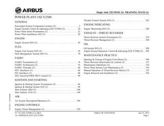
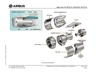
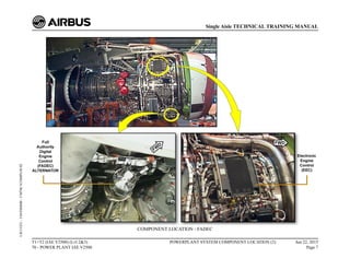
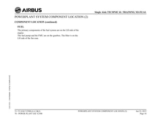
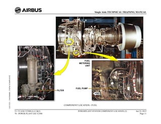
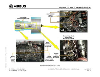
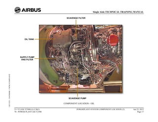
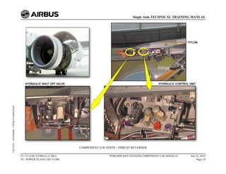
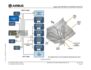
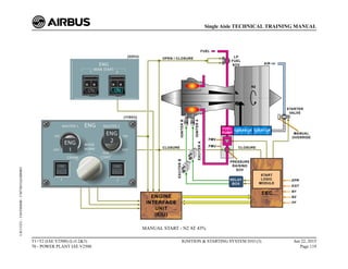
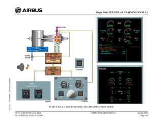
Single Aisle
TECHNICAL TRAINING MANUAL
T1+T2 (IAE V2500) (Lvl 2&3)
POWER PLANT IAE V2500
This document must be used for training purposes only
Under no circumstances should this document be used as a reference
It will not be updated.
All rights reserved
No part of this manual may be reproduced in any form,
by photostat, microfilm, retrieval system, or any other means,
without the prior written permission of AIRBUS S.A.S.
AIRBUS Environmental Recommendation
Please consider your environmental responsability before printing this document.
POWER PLANT IAE V2500
GENERAL
Powerplant System Component Location (2) . . . . . . . . . . . . . . . . . . . . 2
Engine System Control & Indicating (IAE V2500) (2) . . . . . . . . . . . 20
Power Plant Drain Presentation (2) . . . . . . . . . . . . . . . . . . . . . . . . . . 22
Power Plant Installation D/O (3) . . . . . . . . . . . . . . . . . . . . . . . . . . . . 28
ENGINE
Engine System D/O (3) . . . . . . . . . . . . . . . . . . . . . . . . . . . . . . . . . . . 42
FUEL
Engine Fuel System D/O (3) . . . . . . . . . . . . . . . . . . . . . . . . . . . . . . . 58
Heat Management System D/O (3) . . . . . . . . . . . . . . . . . . . . . . . . . . 70
FADEC
FADEC Presentation (2) . . . . . . . . . . . . . . . . . . . . . . . . . . . . . . . . . . . 74
FADEC Architecture (2) . . . . . . . . . . . . . . . . . . . . . . . . . . . . . . . . . . . 76
FADEC Principle (2) . . . . . . . . . . . . . . . . . . . . . . . . . . . . . . . . . . . . . 80
EEC Interfaces (3) . . . . . . . . . . . . . . . . . . . . . . . . . . . . . . . . . . . . . . . 84
EIU Interfaces (3) . . . . . . . . . . . . . . . . . . . . . . . . . . . . . . . . . . . . . . . . 88
EEC Electrical PWR SPLY Control (3) . . . . . . . . . . . . . . . . . . . . . . . 94
IGNITION AND STARTING
Ignition & Starting System Presentation (2) . . . . . . . . . . . . . . . . . . . 96
Ignition & Starting System D/O (3) . . . . . . . . . . . . . . . . . . . . . . . . . . 98
Start Failures (Me) (3) . . . . . . . . . . . . . . . . . . . . . . . . . . . . . . . . . . . 140
Start Failures (US) (3) . . . . . . . . . . . . . . . . . . . . . . . . . . . . . . . . . . . 168
AIR
Air System Description/Operation (3) . . . . . . . . . . . . . . . . . . . . . . . 196
ENGINE CONTROLS
Engine Thrust Management (3) . . . . . . . . . . . . . . . . . . . . . . . . . . . . 220
Throttle Control System D/O (3) . . . . . . . . . . . . . . . . . . . . . . . . . . . 242
ENGINE INDICATING
Engine Monitoring D/O (3) . . . . . . . . . . . . . . . . . . . . . . . . . . . . . . . 248
EXHAUST - THRUST REVERSER
Thrust Reverser System Presentation (2) . . . . . . . . . . . . . . . . . . . . . 274
Thrust Reverser Management (3) . . . . . . . . . . . . . . . . . . . . . . . . . . . 280
OIL
Oil System D/O (3) . . . . . . . . . . . . . . . . . . . . . . . . . . . . . . . . . . . . . . 290
Engine System Operation, Control & Indicating (IAE V2500) (3) . . 302
MAINTENANCE PRACTICE
Opening & Closing of Engine Cowl Doors (2) . . . . . . . . . . . . . . . . 304
Thrust Reverser Deactivation & Lockout (2) . . . . . . . . . . . . . . . . . . 312
Maintenance Operations (2) . . . . . . . . . . . . . . . . . . . . . . . . . . . . . . . 318
Power Plant System Line Maintenance (2) . . . . . . . . . . . . . . . . . . . 338
Manual Operation of Thrust Reverser Sleeves (3) . . . . . . . . . . . . . . 352
Engine Removal and Installation (3) . . . . . . . . . . . . . . . . . . . . . . . . 356
T1+T2 (IAE V2500) (Lvl 2&3)
70 - POWER PLANT IAE V2500
TABLE OF CONTENTS Jun 23, 2015
Page 1
Single Aisle TECHNICAL TRAINING MANUAL
UJC15251
-
U04T0MM0
POWERPLANT SYSTEM COMPONENT LOCATION (2)
SYSTEM OVERVIEW
The IAE V2500-A5 engine is a two-spool, axial-flow, high-bypass-ratio
turbo-fan power engine. The V2500-A5 can power all aircraft types of
the SingleAisle family except theA318.V2500-A5 engines are available
in several thrust ratings.
All the engines have the same basic configuration. A programming plug
on the Electronic Engine Control (EEC) changes the available thrust.
The power plant installation includes the engine, the engine inlet, the
exhaust, the fan cowls and the reverser assemblies. The pylon connects
the engine to the wing structure. The engine is attached to the pylon by
FWD and AFT mounts.
T1+T2 (IAE V2500) (Lvl 2&3)
70 - POWER PLANT IAE V2500
POWERPLANT SYSTEM COMPONENT LOCATION (2) Jun 22, 2015
Page 2
Single Aisle TECHNICAL TRAINING MANUAL
UJC15251
-
U04T0MM0
-
UM70C1COMPLOC02
SYSTEM OVERVIEW
T1+T2 (IAE V2500) (Lvl 2&3)
70 - POWER PLANT IAE V2500
POWERPLANT SYSTEM COMPONENT LOCATION (2) Jun 22, 2015
Page 3
Single Aisle TECHNICAL TRAINING MANUAL
UJC15251
-
U04T0MM0
-
UM70C1COMPLOC02
POWERPLANT SYSTEM COMPONENT LOCATION (2)
SYSTEM OVERVIEW (continued)
THRUST REVERSER SYSTEM
The thrust reverser system operated from the cockpit consists of 2
hydraulically operated translating sleeves.
When the translating sleeve moves aft during deployment, it lifts
blocker doors that redirect the engine fan airflow.
T1+T2 (IAE V2500) (Lvl 2&3)
70 - POWER PLANT IAE V2500
POWERPLANT SYSTEM COMPONENT LOCATION (2) Jun 22, 2015
Page 4
Single Aisle TECHNICAL TRAINING MANUAL
UJC15251
-
U04T0MM0
-
UM70C1COMPLOC02
SYSTEM OVERVIEW - THRUST REVERSER SYSTEM
T1+T2 (IAE V2500) (Lvl 2&3)
70 - POWER PLANT IAE V2500
POWERPLANT SYSTEM COMPONENT LOCATION (2) Jun 22, 2015
Page 5
Single Aisle TECHNICAL TRAINING MANUAL
UJC15251
-
U04T0MM0
-
UM70C1COMPLOC02
POWERPLANT SYSTEM COMPONENT LOCATION (2)
COMPONENT LOCATION
The engine system components are at the following locations.
FADEC
The EEC is on the RH side of the fan case. The FADEC alternator is
on the gearbox.
T1+T2 (IAE V2500) (Lvl 2&3)
70 - POWER PLANT IAE V2500
POWERPLANT SYSTEM COMPONENT LOCATION (2) Jun 22, 2015
Page 6
Single Aisle TECHNICAL TRAINING MANUAL
UJC15251
-
U04T0MM0
-
UM70C1COMPLOC02
COMPONENT LOCATION - FADEC
T1+T2 (IAE V2500) (Lvl 2&3)
70 - POWER PLANT IAE V2500
POWERPLANT SYSTEM COMPONENT LOCATION (2) Jun 22, 2015
Page 7
Single Aisle TECHNICAL TRAINING MANUAL
UJC15251
-
U04T0MM0
-
UM70C1COMPLOC02
POWERPLANT SYSTEM COMPONENT LOCATION (2)
COMPONENT LOCATION (continued)
STARTING
Two ignition boxes are on the RH side of the engine core. The air
starter is on the RH side of the gearbox front face.
T1+T2 (IAE V2500) (Lvl 2&3)
70 - POWER PLANT IAE V2500
POWERPLANT SYSTEM COMPONENT LOCATION (2) Jun 22, 2015
Page 8
Single Aisle TECHNICAL TRAINING MANUAL
UJC15251
-
U04T0MM0
-
UM70C1COMPLOC02
COMPONENT LOCATION - STARTING
T1+T2 (IAE V2500) (Lvl 2&3)
70 - POWER PLANT IAE V2500
POWERPLANT SYSTEM COMPONENT LOCATION (2) Jun 22, 2015
Page 9
Single Aisle TECHNICAL TRAINING MANUAL
UJC15251
-
U04T0MM0
-
UM70C1COMPLOC02
POWERPLANT SYSTEM COMPONENT LOCATION (2)
COMPONENT LOCATION (continued)
FUEL
The primary components of the fuel system are on the LH side of the
engine.
The fuel pump and the FMU are on the gearbox. The filter is on the
LH side of the fan case.
T1+T2 (IAE V2500) (Lvl 2&3)
70 - POWER PLANT IAE V2500
POWERPLANT SYSTEM COMPONENT LOCATION (2) Jun 22, 2015
Page 10
Single Aisle TECHNICAL TRAINING MANUAL
UJC15251
-
U04T0MM0
-
UM70C1COMPLOC02
COMPONENT LOCATION - FUEL
T1+T2 (IAE V2500) (Lvl 2&3)
70 - POWER PLANT IAE V2500
POWERPLANT SYSTEM COMPONENT LOCATION (2) Jun 22, 2015
Page 11
Single Aisle TECHNICAL TRAINING MANUAL
UJC15251
-
U04T0MM0
-
UM70C1COMPLOC02
POWERPLANT SYSTEM COMPONENT LOCATION (2)
COMPONENT LOCATION (continued)
AIR
The next picture shows the compressor airflow control system and
the turbine clearance control system.
On the LH side, there are 2 bleed valves for the 7th
stage and one for
the 10th
stage of the HP compressor.
On the RH side, one more bleed valve is installed for the 7th
stage.
T1+T2 (IAE V2500) (Lvl 2&3)
70 - POWER PLANT IAE V2500
POWERPLANT SYSTEM COMPONENT LOCATION (2) Jun 22, 2015
Page 12
Single Aisle TECHNICAL TRAINING MANUAL
UJC15251
-
U04T0MM0
-
UM70C1COMPLOC02
COMPONENT LOCATION - AIR
T1+T2 (IAE V2500) (Lvl 2&3)
70 - POWER PLANT IAE V2500
POWERPLANT SYSTEM COMPONENT LOCATION (2) Jun 22, 2015
Page 13
Single Aisle TECHNICAL TRAINING MANUAL
UJC15251
-
U04T0MM0
-
UM70C1COMPLOC02
COMPONENT LOCATION - AIR
T1+T2 (IAE V2500) (Lvl 2&3)
70 - POWER PLANT IAE V2500
POWERPLANT SYSTEM COMPONENT LOCATION (2) Jun 22, 2015
Page 14
Single Aisle TECHNICAL TRAINING MANUAL
UJC15251
-
U04T0MM0
-
UM70C1COMPLOC02
This Page Intentionally Left Blank
T1+T2 (IAE V2500) (Lvl 2&3)
70 - POWER PLANT IAE V2500
POWERPLANT SYSTEM COMPONENT LOCATION (2) Jun 22, 2015
Page 15
Single Aisle TECHNICAL TRAINING MANUAL
UJC15251
-
U04T0MM0
-
UM70C1COMPLOC02
POWERPLANT SYSTEM COMPONENT LOCATION (2)
COMPONENT LOCATION (continued)
OIL
The oil tank, the pressure pump, the scavenge pumps and the filter
are on the gearbox.
T1+T2 (IAE V2500) (Lvl 2&3)
70 - POWER PLANT IAE V2500
POWERPLANT SYSTEM COMPONENT LOCATION (2) Jun 22, 2015
Page 16
Single Aisle TECHNICAL TRAINING MANUAL
UJC15251
-
U04T0MM0
-
UM70C1COMPLOC02
COMPONENT LOCATION - OIL
T1+T2 (IAE V2500) (Lvl 2&3)
70 - POWER PLANT IAE V2500
POWERPLANT SYSTEM COMPONENT LOCATION (2) Jun 22, 2015
Page 17
Single Aisle TECHNICAL TRAINING MANUAL
UJC15251
-
U04T0MM0
-
UM70C1COMPLOC02
POWERPLANT SYSTEM COMPONENT LOCATION (2)
COMPONENT LOCATION (continued)
THRUST REVERSER
The hydraulic shut-off valve is in the front lower part of the pylon.
The Hydraulic Control Unit (HCU) is installed on the pylon above
the engine centerline, immediately forward of the C-duct. Access to
the HCU is done from the left side.
T1+T2 (IAE V2500) (Lvl 2&3)
70 - POWER PLANT IAE V2500
POWERPLANT SYSTEM COMPONENT LOCATION (2) Jun 22, 2015
Page 18
Single Aisle TECHNICAL TRAINING MANUAL
UJC15251
-
U04T0MM0
-
UM70C1COMPLOC02
COMPONENT LOCATION - THRUST REVERSER
T1+T2 (IAE V2500) (Lvl 2&3)
70 - POWER PLANT IAE V2500
POWERPLANT SYSTEM COMPONENT LOCATION (2) Jun 22, 2015
Page 19
Single Aisle TECHNICAL TRAINING MANUAL
UJC15251
-
U04T0MM0
-
UM70C1COMPLOC02
ENGINE SYSTEM CONTROL & INDICATING (IAE V2500) (2)
LOCATE CONTROL/INDICATING IN COCKPIT
FADEC POWERING / ENGINE CONTROLS
T1+T2 (IAE V2500) (Lvl 2&3)
70 - POWER PLANT IAE V2500
ENGINE SYSTEM CONTROL & INDICATING (IAE V2500) (2) Jun 22, 2015
Page 20
Single Aisle TECHNICAL TRAINING MANUAL
UJC15251
-
U04T0MM0
-
UM70IZIAELVL202
This Page Intentionally Left Blank
T1+T2 (IAE V2500) (Lvl 2&3)
70 - POWER PLANT IAE V2500
ENGINE SYSTEM CONTROL & INDICATING (IAE V2500) (2) Jun 22, 2015
Page 21
Single Aisle TECHNICAL TRAINING MANUAL
UJC15251
-
U04T0MM0
-
UM70IZIAELVL202
POWER PLANT DRAIN PRESENTATION (2)
GENERAL
The power plant drain system collects fluids which can leak from the
pylon, the engine accessories and drives. The fluids collected from the
power plant can be fuel, oil, hydraulic or water. They are discharged
overboard through the pylon drains and the engine drains.
T1+T2 (IAE V2500) (Lvl 2&3)
70 - POWER PLANT IAE V2500
POWER PLANT DRAIN PRESENTATION (2) Jun 22, 2015
Page 22
Single Aisle TECHNICAL TRAINING MANUAL
UJC15251
-
U04T0MM0
-
UM71P1IAE000002
GENERAL
T1+T2 (IAE V2500) (Lvl 2&3)
70 - POWER PLANT IAE V2500
POWER PLANT DRAIN PRESENTATION (2) Jun 22, 2015
Page 23
Single Aisle TECHNICAL TRAINING MANUAL
UJC15251
-
U04T0MM0
-
UM71P1IAE000002
POWER PLANT DRAIN PRESENTATION (2)
PYLON DRAINS
The engine pylon is divided into 7 compartments; various systems are
routed through these areas. Any leakage from fluid lines is drained
overboard through separate lines in the rear of the pylon.
T1+T2 (IAE V2500) (Lvl 2&3)
70 - POWER PLANT IAE V2500
POWER PLANT DRAIN PRESENTATION (2) Jun 22, 2015
Page 24
Single Aisle TECHNICAL TRAINING MANUAL
UJC15251
-
U04T0MM0
-
UM71P1IAE000002
PYLON DRAINS
T1+T2 (IAE V2500) (Lvl 2&3)
70 - POWER PLANT IAE V2500
POWER PLANT DRAIN PRESENTATION (2) Jun 22, 2015
Page 25
Single Aisle TECHNICAL TRAINING MANUAL
UJC15251
-
U04T0MM0
-
UM71P1IAE000002
POWER PLANT DRAIN PRESENTATION (2)
ENGINE DRAINS
Fluid drained from the oil tank scupper, fuel diverter valve and gear box
mounted accessories, is independently routed to the drain mast. The fuel
drains from the core engine accessories, are routed through a separate
drain line which passes through the bifurcation panel.
T1+T2 (IAE V2500) (Lvl 2&3)
70 - POWER PLANT IAE V2500
POWER PLANT DRAIN PRESENTATION (2) Jun 22, 2015
Page 26
Single Aisle TECHNICAL TRAINING MANUAL
UJC15251
-
U04T0MM0
-
UM71P1IAE000002
ENGINE DRAINS
T1+T2 (IAE V2500) (Lvl 2&3)
70 - POWER PLANT IAE V2500
POWER PLANT DRAIN PRESENTATION (2) Jun 22, 2015
Page 27
Single Aisle TECHNICAL TRAINING MANUAL
UJC15251
-
U04T0MM0
-
UM71P1IAE000002
POWER PLANT INSTALLATION D/O (3)
AIR INTAKE COWL
The air intake cowl is bolted onto the front of the fan case flange. It
includes an anti-ice system, an interphone jack and a P2/ T2 probe.
For removal and installation, the components that follow supply the inlet
cowl:
- 4 hoisting points,
- 36 identical attach fittings,
- 4 alignment dowels.
T1+T2 (IAE V2500) (Lvl 2&3)
70 - POWER PLANT IAE V2500
POWER PLANT INSTALLATION D/O (3) Jun 22, 2015
Page 28
Single Aisle TECHNICAL TRAINING MANUAL
UJC15251
-
U04T0MM0
-
UM71D1IAE000002
AIR INTAKE COWL
T1+T2 (IAE V2500) (Lvl 2&3)
70 - POWER PLANT IAE V2500
POWER PLANT INSTALLATION D/O (3) Jun 22, 2015
Page 29
Single Aisle TECHNICAL TRAINING MANUAL
UJC15251
-
U04T0MM0
-
UM71D1IAE000002
POWER PLANT INSTALLATION D/O (3)
FAN COWL DOORS (LH & RH)
There are two fan cowl doors to give access to the fan case and gearbox
installed accessories.
Four hinges hold each door at the pylon. Four latches latch the door
assembly along the bottom centerline.
Each door is installed with:
- 2 hoisting points, for removal and installation,
- 2 hold-open struts, to open.
Access doors are also installed for the start valve and to service the oil
tank.
NOTE: Note that aerodynamic strakes are installed on the inboard
nacelle side (A320).
As an option, the aerodynamic strakes can be installed at the outboard
nacelle side.
T1+T2 (IAE V2500) (Lvl 2&3)
70 - POWER PLANT IAE V2500
POWER PLANT INSTALLATION D/O (3) Jun 22, 2015
Page 30
Single Aisle TECHNICAL TRAINING MANUAL
UJC15251
-
U04T0MM0
-
UM71D1IAE000002
FAN COWL DOORS (LH & RH)
T1+T2 (IAE V2500) (Lvl 2&3)
70 - POWER PLANT IAE V2500
POWER PLANT INSTALLATION D/O (3) Jun 22, 2015
Page 31
Single Aisle TECHNICAL TRAINING MANUAL
UJC15251
-
U04T0MM0
-
UM71D1IAE000002
POWER PLANT INSTALLATION D/O (3)
THRUST REVERSER "C" DUCTS
The thrust reverser "C" ducts are in two halves installed with cascades,
blocker doors and translating sleeves.
Four hinges hold each half at the pylon. 6 latches latch the halves
assembly along the bottom centerline.
Each half is installed with:
- 3 attachment points for handling,
- 1 opening actuator operated with a hand pump,
- 2 hold-open rods for opening.
The latch assembly includes:
- 1 FWD bumper latch,
- 3 center latches, with access through a hinged access panel,
- 1 aft twin latch.
T1+T2 (IAE V2500) (Lvl 2&3)
70 - POWER PLANT IAE V2500
POWER PLANT INSTALLATION D/O (3) Jun 22, 2015
Page 32
Single Aisle TECHNICAL TRAINING MANUAL
UJC15251
-
U04T0MM0
-
UM71D1IAE000002
THRUST REVERSER "C" DUCTS
T1+T2 (IAE V2500) (Lvl 2&3)
70 - POWER PLANT IAE V2500
POWER PLANT INSTALLATION D/O (3) Jun 22, 2015
Page 33
Single Aisle TECHNICAL TRAINING MANUAL
UJC15251
-
U04T0MM0
-
UM71D1IAE000002
POWER PLANT INSTALLATION D/O (3)
FWD MOUNT
The FWD mount transmits the engine thrust, vertical and side loads. It
is installed on the intermediate case, at the top center of the LP
compressor, with the FWD support shaft of the engine.
The FWD mount is made of 4 main parts:
- two thrust link assemblies,
- a beam assembly,
- a cross beam assembly,
- a support bearing assembly.
The FWD mount is made to be fail-safe. 4 bolts and self-locking nuts
link it to the pylon FWD part.
AFT MOUNT
The aft mount transmits the engine torque, vertical and side loads. It is
free in FWD and aft directions to let engine thermal expand.
It is installed on the case lugs of the turbine exhaust.
The aft mount is made of 3 main parts:
- a beam assembly,
- two side link assemblies,
- a center link assembly.
The aft mount is made to be fail-safe. 4 bolts link it to the pylon aft part.
T1+T2 (IAE V2500) (Lvl 2&3)
70 - POWER PLANT IAE V2500
POWER PLANT INSTALLATION D/O (3) Jun 22, 2015
Page 34
Single Aisle TECHNICAL TRAINING MANUAL
UJC15251
-
U04T0MM0
-
UM71D1IAE000002
FWD MOUNT & AFT MOUNT
T1+T2 (IAE V2500) (Lvl 2&3)
70 - POWER PLANT IAE V2500
POWER PLANT INSTALLATION D/O (3) Jun 22, 2015
Page 35
Single Aisle TECHNICAL TRAINING MANUAL
UJC15251
-
U04T0MM0
-
UM71D1IAE000002
POWER PLANT INSTALLATION D/O (3)
BOOTSTRAP SYSTEM INSTALLATION
The removal and installation of the engine requires the installation of a
bootstrap system on the aircraft pylon. The bootstrap system is composed
of two elements, to be installed at the front and at the rear of the pylon.
Each element permits to attach at its ends the chain pulley blocks assembly
and dynamometers that are used to lower or to lift the transportation stand
attached to the engine.
T1+T2 (IAE V2500) (Lvl 2&3)
70 - POWER PLANT IAE V2500
POWER PLANT INSTALLATION D/O (3) Jun 22, 2015
Page 36
Single Aisle TECHNICAL TRAINING MANUAL
UJC15251
-
U04T0MM0
-
UM71D1IAE000002
BOOTSTRAP SYSTEM INSTALLATION
T1+T2 (IAE V2500) (Lvl 2&3)
70 - POWER PLANT IAE V2500
POWER PLANT INSTALLATION D/O (3) Jun 22, 2015
Page 37
Single Aisle TECHNICAL TRAINING MANUAL
UJC15251
-
U04T0MM0
-
UM71D1IAE000002
BOOTSTRAP SYSTEM INSTALLATION
T1+T2 (IAE V2500) (Lvl 2&3)
70 - POWER PLANT IAE V2500
POWER PLANT INSTALLATION D/O (3) Jun 22, 2015
Page 38
Single Aisle TECHNICAL TRAINING MANUAL
UJC15251
-
U04T0MM0
-
UM71D1IAE000002
This Page Intentionally Left Blank
T1+T2 (IAE V2500) (Lvl 2&3)
70 - POWER PLANT IAE V2500
POWER PLANT INSTALLATION D/O (3) Jun 22, 2015
Page 39
Single Aisle TECHNICAL TRAINING MANUAL
UJC15251
-
U04T0MM0
-
UM71D1IAE000002
POWER PLANT INSTALLATION D/O (3)
ENGINE TRANSPORTATION STAND ATTACHMENT
POINTS
The engine transportation stand, which is used for engine removal and
installation, can be fixed to the engine by means of four trunnions:
- two front trunnions fixed on the LP compressor case, LH side and RH
side,
- two rear trunnions fixed on the LP turbine case, LH side and RH side.
T1+T2 (IAE V2500) (Lvl 2&3)
70 - POWER PLANT IAE V2500
POWER PLANT INSTALLATION D/O (3) Jun 22, 2015
Page 40
Single Aisle TECHNICAL TRAINING MANUAL
UJC15251
-
U04T0MM0
-
UM71D1IAE000002
ENGINE TRANSPORTATION STAND ATTACHMENT POINTS
T1+T2 (IAE V2500) (Lvl 2&3)
70 - POWER PLANT IAE V2500
POWER PLANT INSTALLATION D/O (3) Jun 22, 2015
Page 41
Single Aisle TECHNICAL TRAINING MANUAL
UJC15251
-
U04T0MM0
-
UM71D1IAE000002
ENGINE SYSTEM D/O (3)
ENGINE CHARACTERISTICS
The Airbus A319/A320/A321 are powered by two International Aero
Engines (IAE) V2500- A5 turbofan engines.
These engines can produce a thrust ranging from 22,000 lbs (9,980 kg)
to 33,000 lbs (14,970 kg) depending on the aircraft version set by the
engine data-programming plug.
PYLON
The engines are attached to the lower surface of the wings by pylons.
The pylons supply an interface between the engine and the aircraft
for electrics and fluids.
NACELLE
The engine is enclosed in the nacelle, which supplies aerodynamic
airflow around the engine and ensures protection for the accessories.
ENGINE CONTROL
The engine includes a FullAuthority Digital Engine Control (FADEC),
which supplies engine control, engine monitoring and help for
maintenance and trouble shooting.
T1+T2 (IAE V2500) (Lvl 2&3)
70 - POWER PLANT IAE V2500
ENGINE SYSTEM D/O (3) Jun 22, 2015
Page 42
Single Aisle TECHNICAL TRAINING MANUAL
UJC15251
-
U04T0MM0
-
UM72D1IAE000002
ENGINE CHARACTERISTICS - PYLON ... ENGINE CONTROL
T1+T2 (IAE V2500) (Lvl 2&3)
70 - POWER PLANT IAE V2500
ENGINE SYSTEM D/O (3) Jun 22, 2015
Page 43
Single Aisle TECHNICAL TRAINING MANUAL
UJC15251
-
U04T0MM0
-
UM72D1IAE000002
ENGINE SYSTEM D/O (3)
ENGINE BEARINGS
The No.1, 2 and 3 (front) bearing compartment is built into the case
module and contains the support bearings for the low spool and high
spool stubshafts.
The No.4 bearing compartment is part of the diffuser/combustor module
and the No 5 is located on the exhaust case.
NO.1 AND NO.2 BEARINGS
The No.1 ball bearing carries the axial loads generated by the LP rotor
system. This bearing is a split inner race ball bearing. The No.1 bearing
support provides structural support for the No.1 bearing, oil supply
tube and No.1 bearing seal support.
The No.2 bearing is a cylindrical roller bearing with a shouldered
outer race. The No.2 roller bearing carries the radial loads generated
by the front part of the LP rotor system.
NO.3 BEARING
The No.3 ball bearing, internal gearbox and support assembly are
located in the internal gearbox and drive section of the Low Pressure
Compressor (LPC) intermediate case module. The No.3 ball bearing
carries the axial loads generated by the HP rotor system.
NO.4 AND NO.5 BEARINGS
The No.4 bearing is a roller bearing, which is secured onto the bearing
support assembly. Rotor support is transmitted through the bearing
and bearing support to the diffuser case inner wall. The No.4 roller
bearing carries the radial loads generated by the HP rotor system.
The Low Pressure Turbine (LPT) shaft is supported at the rear end
by the No.5 roller bearing, which is located on the exhaust case. The
No.5 bearing inner race is secured on the shaft by an interference fit
and is secured against the seal assembly by a coupling nut. The outer
race is loosely fitted in the bore of the bearing support.
T1+T2 (IAE V2500) (Lvl 2&3)
70 - POWER PLANT IAE V2500
ENGINE SYSTEM D/O (3) Jun 22, 2015
Page 44
Single Aisle TECHNICAL TRAINING MANUAL
UJC15251
-
U04T0MM0
-
UM72D1IAE000002
ENGINE BEARINGS - NO.1 AND NO.2 BEARINGS ... NO.4 AND NO.5 BEARINGS
T1+T2 (IAE V2500) (Lvl 2&3)
70 - POWER PLANT IAE V2500
ENGINE SYSTEM D/O (3) Jun 22, 2015
Page 45
Single Aisle TECHNICAL TRAINING MANUAL
UJC15251
-
U04T0MM0
-
UM72D1IAE000002
ENGINE SYSTEM D/O (3)
COMPRESSOR
The compressor section includes three modules:
- LPC (fan) module assembly,
- LPC/intermediate case module,
- HPC module.
LPC FAN MODULE ASSEMBLY
The LPC (fan) module is a rotor assembly, which includes twenty-two
blades and a disk. Rotation of the rotor causes air to be ingested into
the front of the engine and compressed.
A large proportion of the compressed air is delivered through the fan
discharge duct to the exhaust nozzle to supply the majority of engine
thrust. The remainder of the compressed air goes into the booster
section for further compression by the booster.
LPC INTERMEDIATE CASE MODULE
The LPC intermediate case module includes a four stages axial flow
booster section, a fan case section and an internal gearbox and drive
section.
The fan case section of LPC/intermediate case module makes the
outer annulus of the cold stream duct.
HPC
The HPC is a ten stages axial flow module. It comprises the HPC,
blades, the front casing and variable vanes, the rear casing which
contains the fixed stators and shapes the bleed manifolds.
T1+T2 (IAE V2500) (Lvl 2&3)
70 - POWER PLANT IAE V2500
ENGINE SYSTEM D/O (3) Jun 22, 2015
Page 46
Single Aisle TECHNICAL TRAINING MANUAL
UJC15251
-
U04T0MM0
-
UM72D1IAE000002
COMPRESSOR - LPC FAN MODULE ASSEMBLY ... HPC
T1+T2 (IAE V2500) (Lvl 2&3)
70 - POWER PLANT IAE V2500
ENGINE SYSTEM D/O (3) Jun 22, 2015
Page 47
Single Aisle TECHNICAL TRAINING MANUAL
UJC15251
-
U04T0MM0
-
UM72D1IAE000002
ENGINE SYSTEM D/O (3)
TURBINE SECTION
The turbine section includes the HPT and LPT modules.
The HPT is a two stages turbine and drives the HPC and the accessory
gearbox.
The LPT is a five stages module attached at the rear flange of the HPT
module.
Active Clearance Control (ACC) is used to control seal clearances and
to supply structural cooling.
HPT SECTION
The HPT rotor and stator assembly includes stage 1 turbine rotor
assembly; a HPT case and vane assembly; a stage 2 HPT airseal; and
a stage 2 turbine rotor assembly.
LPT CASE, VANES AND STATIC SEALS
The LPT case, stator vanes and seals are the static parts of the LPT
assembly. This assembly includes five stages of vanes, static air seals,
and diffuser of inner and outer segments assembled in a casing.
LPT ROTOR
The LPT rotor is a bolted configuration including five disks and
associated blades and rotating air seals.
LPT SHAFT
The LPT Shaft joins the LPT assembly with the LPC and the Fan.
The shaft is bolted to the LPT at the LPT rotor disk stage 6 and extends
forward through the engine.
TEC AND Nº5 BEARING ASSEMBLY
The Turbine Exhaust Case (TEC) is used to straighten the turbine
exhaust gases, and supplies structural support for the No.5 bearing.
ACTIVE CLEARANCE CONTROL SYSTEM (ACC)
The ACC system uses air to control the tip clearances of the HPT and
LPT blades.
T1+T2 (IAE V2500) (Lvl 2&3)
70 - POWER PLANT IAE V2500
ENGINE SYSTEM D/O (3) Jun 22, 2015
Page 48
Single Aisle TECHNICAL TRAINING MANUAL
UJC15251
-
U04T0MM0
-
UM72D1IAE000002
TURBINE SECTION - HPT SECTION ... ACTIVE CLEARANCE CONTROL SYSTEM (ACC)
T1+T2 (IAE V2500) (Lvl 2&3)
70 - POWER PLANT IAE V2500
ENGINE SYSTEM D/O (3) Jun 22, 2015
Page 49
Single Aisle TECHNICAL TRAINING MANUAL
UJC15251
-
U04T0MM0
-
UM72D1IAE000002
ENGINE SYSTEM D/O (3)
TURBINE SECTION OPERATION
The HPT rotor and stator assembly supplies the rotational driving force
to the HPC and accessory gearbox by extracting energy from the hot
combustion gases, and releases a gas stream to the LPT in order to drive
the LPC and the fan through the LPT shaft.
Exhaust gas from the LPT goes through a nozzle to supply propulsive
thrust.
Blade tip clearance and LPT case heat expansion are controlled by an
external ACC system. Fan discharge air is directed externally to the LPT
case via the ACC tubes. This controls the heat expansion of the LPT case
and optimizes the blade tip clearances.
T1+T2 (IAE V2500) (Lvl 2&3)
70 - POWER PLANT IAE V2500
ENGINE SYSTEM D/O (3) Jun 22, 2015
Page 50
Single Aisle TECHNICAL TRAINING MANUAL
UJC15251
-
U04T0MM0
-
UM72D1IAE000002
TURBINE SECTION OPERATION
T1+T2 (IAE V2500) (Lvl 2&3)
70 - POWER PLANT IAE V2500
ENGINE SYSTEM D/O (3) Jun 22, 2015
Page 51
Single Aisle TECHNICAL TRAINING MANUAL
UJC15251
-
U04T0MM0
-
UM72D1IAE000002
ENGINE SYSTEM D/O (3)
ACCESSORY GEARBOX
The accessory gearbox has an angle gearbox assembly, a main gear
assembly and external components.
The angle gearbox transmits power from the engine to the main gearbox
and from the starter on the main gearbox to the engine.
The oil pressure pump receives the movement through the fuel pump
drive gearshaft and supplies oil under pressure to the engine bearings and
accessory gearbox.
The deoiler receives the movement through the Integrated Drive Generator
(IDG) system gearshaft and separates air and oil by centrifugal action.
The deaerated oil goes back to the oil system and the clean air is bled
overboard.
T1+T2 (IAE V2500) (Lvl 2&3)
70 - POWER PLANT IAE V2500
ENGINE SYSTEM D/O (3) Jun 22, 2015
Page 52
Single Aisle TECHNICAL TRAINING MANUAL
UJC15251
-
U04T0MM0
-
UM72D1IAE000002
ACCESSORY GEARBOX
T1+T2 (IAE V2500) (Lvl 2&3)
70 - POWER PLANT IAE V2500
ENGINE SYSTEM D/O (3) Jun 22, 2015
Page 53
Single Aisle TECHNICAL TRAINING MANUAL
UJC15251
-
U04T0MM0
-
UM72D1IAE000002
ENGINE SYSTEM D/O (3)
AERODYNAMIC STATIONS
Here are the main aerodynamic stations corresponding to the pressure
and temperature sensors installed on the engine:
- STA 1: intake /engine inlet interfaces,
- STA 2: fan inlet,
- STA 12.5: fan exit,
- STA 2.5: LP compressor exit,
- STA 3: HP compressor exit,
- STA 4: combustion section exit,
- STA 4.5: HP turbine exit,
- STA 4.9: LP turbine exit.
Here is the compressor stage numbering:
- Stage 1.fan,
- Stages 1.5 to 2.5: booster (LP compressor),
- Stages 3 to 12: HP compressor.
Here is the turbine stage numbering:
- Stages 1 and 2: HP turbine,
- Stages 3 to 7: LP turbine.
T1+T2 (IAE V2500) (Lvl 2&3)
70 - POWER PLANT IAE V2500
ENGINE SYSTEM D/O (3) Jun 22, 2015
Page 54
Single Aisle TECHNICAL TRAINING MANUAL
UJC15251
-
U04T0MM0
-
UM72D1IAE000002
AERODYNAMIC STATIONS
T1+T2 (IAE V2500) (Lvl 2&3)
70 - POWER PLANT IAE V2500
ENGINE SYSTEM D/O (3) Jun 22, 2015
Page 55
Single Aisle TECHNICAL TRAINING MANUAL
UJC15251
-
U04T0MM0
-
UM72D1IAE000002
ENGINE SYSTEM D/O (3)
BORESCOPE PORTS
Several ports are provided on the engine for borescope inspection.
T1+T2 (IAE V2500) (Lvl 2&3)
70 - POWER PLANT IAE V2500
ENGINE SYSTEM D/O (3) Jun 22, 2015
Page 56
Single Aisle TECHNICAL TRAINING MANUAL
UJC15251
-
U04T0MM0
-
UM72D1IAE000002
BORESCOPE PORTS
T1+T2 (IAE V2500) (Lvl 2&3)
70 - POWER PLANT IAE V2500
ENGINE SYSTEM D/O (3) Jun 22, 2015
Page 57
Single Aisle TECHNICAL TRAINING MANUAL
UJC15251
-
U04T0MM0
-
UM72D1IAE000002
ENGINE FUEL SYSTEM D/O (3)
FUEL FEED
The engine fuel system is designed to provide fuel flow into the
combustion chamber, servo fuel for actuation of the compressor airflow
control and turbine clearance control systems and cooling for engine oil
and Integrated Drive Generator (IDG) oil.
The fuel coming from the aircraft tanks supplies the Low Pressure (LP)
fuel pump then provides engine oil cooling, through the fuel cooled oil
cooler. It then passes through the filter before entering into the High
Pressure (HP) pump then into the Fuel Metering Unit (FMU). A fuel
Differential Pressure (DELTA P) Switch provides indication to the cockpit
if the filter is clogged. A fuel temperature sensor is installed at the fuel
filter outlet for the fuel diverter and return valve operation.
T1+T2 (IAE V2500) (Lvl 2&3)
70 - POWER PLANT IAE V2500
ENGINE FUEL SYSTEM D/O (3) Jun 22, 2015
Page 58
Single Aisle TECHNICAL TRAINING MANUAL
UJC15251
-
U04T0MM0
-
UM73D1IAE000002
FUEL FEED
T1+T2 (IAE V2500) (Lvl 2&3)
70 - POWER PLANT IAE V2500
ENGINE FUEL SYSTEM D/O (3) Jun 22, 2015
Page 59
Single Aisle TECHNICAL TRAINING MANUAL
UJC15251
-
U04T0MM0
-
UM73D1IAE000002
ENGINE FUEL SYSTEM D/O (3)
METERED FUEL
The fuel from the fuel pump assembly goes through a fuel metering valve,
an overspeed valve and a pressure raising and Shut-Off Valve (SOV)
included in the FMU. The fuel flow is then routed to a fuel distribution
valve, which supplies 20 nozzles through 10 manifolds. The Electronic
Engine Control (EEC) controls the valves included in the FMU through
Torque Motors (TMs) to carry out fuel metering, overspeed protection,
pressure raising and shut-off functions. A flow adjuster installed below
the metering valve is used for the fuel flow adjustment between "high
flow" and "normal flow" by a maintenance action.
NOTE: Note: The LP SOV, pressure raising and SOV close when the
ENGine MASTER lever is set to OFF. The pressure raising
and SOV could be automatically closed by the EEC, during
auto start only, to abort in case of an incident.
T1+T2 (IAE V2500) (Lvl 2&3)
70 - POWER PLANT IAE V2500
ENGINE FUEL SYSTEM D/O (3) Jun 22, 2015
Page 60
Single Aisle TECHNICAL TRAINING MANUAL
UJC15251
-
U04T0MM0
-
UM73D1IAE000002
METERED FUEL
T1+T2 (IAE V2500) (Lvl 2&3)
70 - POWER PLANT IAE V2500
ENGINE FUEL SYSTEM D/O (3) Jun 22, 2015
Page 61
Single Aisle TECHNICAL TRAINING MANUAL
UJC15251
-
U04T0MM0
-
UM73D1IAE000002
ENGINE FUEL SYSTEM D/O (3)
DIVERTED FUEL
Part of the fuel is used to provide adequate cooling of the engine oil and
IDG oil, and to maintain engine fuel and oil temperatures within specified
limits. These functions are controlled through a fuel diverter and return
valve, which incorporates a module to permit fuel to be returned to the
aircraft tanks under certain conditions. The EEC processes the operation
modes of the fuel diverter and return valve by software logic. The logic
is generated around the limiting temperatures of fuel and oil, to provide
the heat management system.
T1+T2 (IAE V2500) (Lvl 2&3)
70 - POWER PLANT IAE V2500
ENGINE FUEL SYSTEM D/O (3) Jun 22, 2015
Page 62
Single Aisle TECHNICAL TRAINING MANUAL
UJC15251
-
U04T0MM0
-
UM73D1IAE000002
DIVERTED FUEL
T1+T2 (IAE V2500) (Lvl 2&3)
70 - POWER PLANT IAE V2500
ENGINE FUEL SYSTEM D/O (3) Jun 22, 2015
Page 63
Single Aisle TECHNICAL TRAINING MANUAL
UJC15251
-
U04T0MM0
-
UM73D1IAE000002
ENGINE FUEL SYSTEM D/O (3)
SERVO FUEL
In the FMU, a servo regulator provides the HP fuel to:
- the FMU TM servo valves,
- the Air Cooled Oil Cooler (ACOC) actuator,
- the booster stage bleed valve actuators,
- the Variable Stator Vane (VSV) actuator,
- the Active Clearance Control (ACC) actuator.
The servo regulator of the FMU regulates a fuel pressure to the
compressor airflow control systems, i.e. the booster stage bleed valve
and VSV and the pressure of the turbine ACC system.
T1+T2 (IAE V2500) (Lvl 2&3)
70 - POWER PLANT IAE V2500
ENGINE FUEL SYSTEM D/O (3) Jun 22, 2015
Page 64
Single Aisle TECHNICAL TRAINING MANUAL
UJC15251
-
U04T0MM0
-
UM73D1IAE000002
SERVO FUEL
T1+T2 (IAE V2500) (Lvl 2&3)
70 - POWER PLANT IAE V2500
ENGINE FUEL SYSTEM D/O (3) Jun 22, 2015
Page 65
Single Aisle TECHNICAL TRAINING MANUAL
UJC15251
-
U04T0MM0
-
UM73D1IAE000002
ENGINE FUEL SYSTEM D/O (3)
EEC CONTROL
The EEC controls the operation of the FMU TM servo valves, the fuel
diverter and return valve, theACOC actuator, the actuators of the booster
stage bleed valve, VSV and ACC systems. The EEC performs control
functions and fault analysis required to regulate the fuel and to maintain
the engine operation in all conditions. In the event of loss of control
functions on both channels, each servo valve and actuator has a fail-safe
position.
In the event of overspeed, due to malfunction of fuel flow control, EEC
activates a torque motor which drives the overspeed valve to reduce fuel
flow to a minimum value. In this case EEC triggers the warning message:
"ENG 1(2) FADEC FAULT".
T1+T2 (IAE V2500) (Lvl 2&3)
70 - POWER PLANT IAE V2500
ENGINE FUEL SYSTEM D/O (3) Jun 22, 2015
Page 66
Single Aisle TECHNICAL TRAINING MANUAL
UJC15251
-
U04T0MM0
-
UM73D1IAE000002
EEC CONTROL
T1+T2 (IAE V2500) (Lvl 2&3)
70 - POWER PLANT IAE V2500
ENGINE FUEL SYSTEM D/O (3) Jun 22, 2015
Page 67
Single Aisle TECHNICAL TRAINING MANUAL
UJC15251
-
U04T0MM0
-
UM73D1IAE000002
ENGINE FUEL SYSTEM D/O (3)
ENGINE SHUT DOWN
Normal Engine Shut Down:
When the Master switch is set from On to OFF, an electrical signal is
sent directly to the Pressure Raising and Shut OffValve (PRSOV) Torque
Motor (TM). The PRSOV closes and the fuel flow to the Fuel Distribution
Valve and the combustion chamber is stopped.
A second electrical signal is sent to the two motors of the LP Valve,
which is controlled to close, to isolate the aircraft fuel system from the
engine. The EEC closes the Fuel Metering Valve (FMV).
In case of an engine fire, after the Master Switch is set to OFF, the Fire
Pushbutton is released out to confirm the closure of the LP Valve.
T1+T2 (IAE V2500) (Lvl 2&3)
70 - POWER PLANT IAE V2500
ENGINE FUEL SYSTEM D/O (3) Jun 22, 2015
Page 68
Single Aisle TECHNICAL TRAINING MANUAL
UJC15251
-
U04T0MM0
-
UM73D1IAE000002
ENGINE SHUT DOWN
T1+T2 (IAE V2500) (Lvl 2&3)
70 - POWER PLANT IAE V2500
ENGINE FUEL SYSTEM D/O (3) Jun 22, 2015
Page 69
Single Aisle TECHNICAL TRAINING MANUAL
UJC15251
-
U04T0MM0
-
UM73D1IAE000002
HEAT MANAGEMENT SYSTEM D/O (3)
GENERAL
Heating and cooling of the fuel, engine oil and Integrated Drive Generator
(IDG) oil is performed by the fuel cooled oil cooler, the Air Cooled Oil
Cooler (ACOC) and the IDG fuel cooled oil cooler under the control of
the Electronic Engine Control (EEC). The EEC acts on the heat
management system through the Fuel Diverter and Return to tank Valve
(FDRV) and the ACOC modulating valve.
ACOC MODULATING VALVE
Oil heated by the engine passes through the ACOC and then to the fuel
cooled oil cooler. The ACOC modulating valve regulates a bleed part of
fan airflow crossing theACOC to maintain both oil and fuel temperatures
within acceptable minimum and maximum limits.
FUEL DIVERTERAND RETURNTOTANKVALVE (FDRV)
The fuel diverter valve and the return to tank valve are enclosed in the
same housing. The FDRV maintain fuel, engine oil and IDG oil
temperatures within limits by minimizing ACOC cooling air usage. The
two-position diverter valve works by managing the fuel recirculation
inside the engine fuel system. The return to tank valve will divert a
modulated proportion of the LP fuel back to the aircraft tanks.
CONTROL
The EEC controls the heat management system through 4 modes of
operation taking into account 3 parameters of temperature:
- engine fuel,
- engine oil,
- IDG oil.
The temperature of the aircraft fuel tanks and the engine power setting
are parameters used for inhibition of fuel return to aircraft tanks.
NOTE: Note: The 4 modes of operation are modes 1, 3, 4 and 5:
- modes 1 and 4 are return to tank modes,
- modes 3 and 5 are no return to tank modes.
T1+T2 (IAE V2500) (Lvl 2&3)
70 - POWER PLANT IAE V2500
HEAT MANAGEMENT SYSTEM D/O (3) Jun 22, 2015
Page 70
Single Aisle TECHNICAL TRAINING MANUAL
UJC15251
-
U04T0MM0
-
UM73D6IAE000001
GENERAL ... CONTROL
T1+T2 (IAE V2500) (Lvl 2&3)
70 - POWER PLANT IAE V2500
HEAT MANAGEMENT SYSTEM D/O (3) Jun 22, 2015
Page 71
Single Aisle TECHNICAL TRAINING MANUAL
UJC15251
-
U04T0MM0
-
UM73D6IAE000001
HEAT MANAGEMENT SYSTEM D/O (3)
COMPONENTS
IDG FUEL COOLED OIL COOLER
The IDG Fuel Cooled Oil Cooler (FCOC) is installed on the LH side
of the LP compressor intermediate case.
FUEL DIVERTER AND RETURN TO TANK VALVE
(FDRV)
The FDRV is installed on the fuel filter.
AIR COOLED OIL COOLER
The ACOC is mounted on the RH side of the engine fan case.
T1+T2 (IAE V2500) (Lvl 2&3)
70 - POWER PLANT IAE V2500
HEAT MANAGEMENT SYSTEM D/O (3) Jun 22, 2015
Page 72
Single Aisle TECHNICAL TRAINING MANUAL
UJC15251
-
U04T0MM0
-
UM73D6IAE000001
COMPONENTS - IDG FUEL COOLED OIL COOLER ... AIR COOLED OIL COOLER
T1+T2 (IAE V2500) (Lvl 2&3)
70 - POWER PLANT IAE V2500
HEAT MANAGEMENT SYSTEM D/O (3) Jun 22, 2015
Page 73
Single Aisle TECHNICAL TRAINING MANUAL
UJC15251
-
U04T0MM0
-
UM73D6IAE000001
FADEC PRESENTATION (2)
PURPOSE
The Full Authority Digital Engine Control (FADEC) system provides
full range engine control throughout all flight and operational phases. It
consists of a dual channel Electronic Engine Control (EEC) and its
peripheral components and sensors.
FADEC FUNCTIONS
The FADEC provides the engine system regulation and scheduling to
control the thrust and optimize the engine operation. The FADEC
provides:
- power setting with EPR or N1 back-up mode,
- P2/T2 heating,
- acceleration and deceleration times,
- idle speed governing,
- overspeed limits for N1 and N2,
- Fuel Flow (FF) control,
- Variable Stator Vane system (VSV) control,
- compressor handling bleed valves control,
- booster stage bleed valve system control,
- High Pressure (HP)/Low Pressure (LP) turbineActive Clearance Control
(ACC),
- automatic and manual engine starting,
- thrust reverser control,
- oil and fuel temperature management through the heat management
system.
FADEC BENEFITS
The application of a FADEC system provides multiple benefits:
- it saves weight and fuel by a full range control of the gas generator,
- it reduces pilot workload and maintenance cost,
- it allows the optimum adaptation of thrust rating schedules to the A/C
needs.
POWER SUPPLY
The FADEC system is self-powered by a dedicated Permanent Magnet
Alternator (PMA) when N2 is greater than 10%. The EEC is powered by
the aircraft 28 VDC electrical network for starting, as a backup and for
testing with the engine not running. 115VAC is used for the power supply
of the ignition system and the P2/T2 probe heating. The PMA also
provides the EEC Channel A and Channel B with the N2 rotation speed.
T1+T2 (IAE V2500) (Lvl 2&3)
70 - POWER PLANT IAE V2500
FADEC PRESENTATION (2) Jun 22, 2015
Page 74
Single Aisle TECHNICAL TRAINING MANUAL
UJC15251
-
U04T0MM0
-
UM73P1IAE000002
PURPOSE ... POWER SUPPLY
T1+T2 (IAE V2500) (Lvl 2&3)
70 - POWER PLANT IAE V2500
FADEC PRESENTATION (2) Jun 22, 2015
Page 75
Single Aisle TECHNICAL TRAINING MANUAL
UJC15251
-
U04T0MM0
-
UM73P1IAE000002
FADEC ARCHITECTURE (2)
DUAL CHANNEL
The Full Authority Digital Engine Control (FADEC) system is fully
redundant and built around two independent control channels. Dual inputs,
dual outputs and automatic switchover from one channel to the other
eliminate any dormant failure. The Electronic Engine Control (EEC)
consists of two channels A and B. Each channel can control the different
components of the engine systems. Channels A and B are permanently
operational. The channel in control manages the system.
DUAL INPUTS
All control inputs to the FADEC system are doubled. Only some
secondary parameters used for monitoring and indicating are single. To
increase the fault tolerant design, the parameters are exchanged between
the two control channels inside the EEC via the cross channel data link.
HARDWIRED INPUTS
Most of the information exchanged between the A/C and the EEC is
transmitted over digital data buses, some signals over a single line. In
addition, some signals are hard-wired directly from the A/C to the EEC.
The Throttle Lever Angle (TLA) is transformed by resolvers into a
Throttle Resolver Angle (TRA) and transmitted directly to the EEC. 1°
of TLA corresponds to 1.9° of TRA.
DUAL OUTPUTS
All the EEC outputs are double, but only the channel in control supplies
the engine control signals to the various receptors such as torque motors
and solenoids. The other channel calculation is used for crosschecking.
BITE CAPABILITY
The EEC is equipped with a BITE system which provides maintenance
information and test capabilities via the MCDU.
FAULT STRATEGY
Using the BITE system, the EEC can detect and isolate failures. It also
allows the EEC to switch engine control from the faulty channel to the
healthy one. Depending on the nature of the failure, the EEC will behave
differently in case of:
- single input signal failure, there is no channel changeover, the channel
in control uses the inputs from the other channel through the cross channel
data link,
- dual input signal failure, the system runs on synthesized values of the
healthiest channel,
- single output signal failure, there is an automatic switchover to the
standby active channel,
- complete output signal failure, there is no longer any current to drive
the torque motors or solenoids, the related component will go to the
"fail-safe" position.
FAIL-SAFE CONTROL
If a channel is faulty and the channel in control is unable to ensure one
engine function, this control is moved to a fail-safe position. Example:
if the channel is faulty and the remaining channel in control is unable to
control the Variable Stator Vane (VSV) position, the vanes are set to the
fail-safe open position.
MAIN INTERFACES
To perform all its tasks, the EEC interfaces with A/C computers, either
directly or via the Engine Interface Unit (EIU), which is an interface
T1+T2 (IAE V2500) (Lvl 2&3)
70 - POWER PLANT IAE V2500
FADEC ARCHITECTURE (2) Jun 22, 2015
Page 76
Single Aisle TECHNICAL TRAINING MANUAL
UJC15251
-
U04T0MM0
-
UM73P2IAE000002
concentrator between the A/C systems and the FADEC system. There is
one EIU for each engine, located in the avionics bay.
EEC INPUTS
The EEC receives inputs from:
- the Landing Gear Control and Interface Unit (LGCIU),
- the Air Data Inertial Reference Units (ADIRUs),
- the Flight Control Unit (FCU),
- the Environmental Control System (ECS) computers,
- the Centralized Fault Display Interface Unit (CFDIU),
- the cockpit engine controls including TRA, fire and anti-ice systems.
EEC OUPUTS
The EEC sends outputs to:
- the Bleed air Monitoring Computers (BMCs),
- the Electronic Control Box (ECB),
- the Flight Warning Computers (FWCs),
- the Display Management Computers (DMCs),
- the Flight Management and Guidance Computers (FMGCs),
- the CFDIU,
- the Data Management Unit (DMU), in option.
T1+T2 (IAE V2500) (Lvl 2&3)
70 - POWER PLANT IAE V2500
FADEC ARCHITECTURE (2) Jun 22, 2015
Page 77
Single Aisle TECHNICAL TRAINING MANUAL
UJC15251
-
U04T0MM0
-
UM73P2IAE000002
DUAL CHANNEL ... MAIN INTERFACES
T1+T2 (IAE V2500) (Lvl 2&3)
70 - POWER PLANT IAE V2500
FADEC ARCHITECTURE (2) Jun 22, 2015
Page 78
Single Aisle TECHNICAL TRAINING MANUAL
UJC15251
-
U04T0MM0
-
UM73P2IAE000002
This Page Intentionally Left Blank
T1+T2 (IAE V2500) (Lvl 2&3)
70 - POWER PLANT IAE V2500
FADEC ARCHITECTURE (2) Jun 22, 2015
Page 79
Single Aisle TECHNICAL TRAINING MANUAL
UJC15251
-
U04T0MM0
-
UM73P2IAE000002
FADEC PRINCIPLE (2)
GENERAL
The Full Authority Digital Engine Control (FADEC) system manages
the engine thrust and optimizes the performance.
FADEC
The FADEC consists of the Electronic Engine Control (EEC) and its
peripheral components and sensors used for control and monitoring. The
EEC is in relation with the otherA/C systems through the Engine Interface
Unit (EIU). The primary parameters Engine Pressure Ratio (EPR), Low
Pressure Rotor Speed (N1), High Pressure Rotor Speed (N2), Exhaust
Gas Temperature (EGT), and Fuel Flow (FF) are sent directly by the EEC
to the ECAM.
Secondary parameters:
- the oil quantity and oil pressure are sent to the DMCs by the SDACs.
In case of SDACs failure, the EIU sends data to DMCs by the FWCs,
- the oil temperature is sent by the EIU to DMCs via thhe FWCs,
- the fuel used data is directly sent to DMCs via the EEC,
- the vibration parameters are sent by the EIVMU to DMCs via the
SDACs.
EIU
Each EIU, located in the avionics bay, is an interface concentrator between
the airframe and the corresponding FADEC located on the engine. There
is one EIU for each engine.
POWER MANAGEMENT
The FADEC provides automatic engine thrust control and thrust parameter
limit computation. The thrust is computed according to the Engine
Pressure Ratio (EPR) in normal mode or N1 in back-up mode. In fact,
when the Engine Pressure Ratio (EPR) mode is no longer operational the
FADEC automatically reverts to the N1 alternate control mode. The
FADEC manages power according to two thrust modes:
- manual mode depending on the Throttle Resolver Angle (TRA),
- auto thrust mode depending on the auto thrust function generated by
the Auto Flight System (AFS).
The FADEC also provides two idle mode selections:
- approach idle,
- minimum idle.
Approach idle is obtained when the slats are extended. Minimum idle
can be modulated up to approach idle depending on air conditioning,
engine anti-ice and wing anti-ice demands.
ENGINE LIMITS
The FADEC provides overspeed protection for N1 and N2, in order to
prevent the engine from exceeding limits, and also monitors the EGT
and Engine Pressure Ratio (EPR).
ENGINE SYSTEMS
The FADEC provides optimal engine operation by controlling the:
- FF,
- compressor airflow and turbine clearance.
IGNITION AND STARTING
The FADEC controls the engine start sequence. It monitors N1, N2, and
EGT parameters and can abort or recycle an engine start. The FADEC
controls the ignition and starting in automatic or manual mode when
initiated from the ENGine start or ENGine MANual START panels.
THRUST REVERSER
The FADEC supervises the thrust reverser operation entirely.
T1+T2 (IAE V2500) (Lvl 2&3)
70 - POWER PLANT IAE V2500
FADEC PRINCIPLE (2) Jun 22, 2015
Page 80
Single Aisle TECHNICAL TRAINING MANUAL
UJC15251
-
U04T0MM0
-
UM73P3IAE000002
NOTE: Note: during reverse operation the thrust is controlled as a
function of N1.
T1+T2 (IAE V2500) (Lvl 2&3)
70 - POWER PLANT IAE V2500
FADEC PRINCIPLE (2) Jun 22, 2015
Page 81
Single Aisle TECHNICAL TRAINING MANUAL
UJC15251
-
U04T0MM0
-
UM73P3IAE000002
GENERAL ... THRUST REVERSER
T1+T2 (IAE V2500) (Lvl 2&3)
70 - POWER PLANT IAE V2500
FADEC PRINCIPLE (2) Jun 22, 2015
Page 82
Single Aisle TECHNICAL TRAINING MANUAL
UJC15251
-
U04T0MM0
-
UM73P3IAE000002
This Page Intentionally Left Blank
T1+T2 (IAE V2500) (Lvl 2&3)
70 - POWER PLANT IAE V2500
FADEC PRINCIPLE (2) Jun 22, 2015
Page 83
Single Aisle TECHNICAL TRAINING MANUAL
UJC15251
-
U04T0MM0
-
UM73P3IAE000002
EEC INTERFACES (3)
GENERAL
In order to provide a full range of engine control and monitoring, the
Electronic Engine Control (EEC) interfaces with the following sub
systems:
- air data computers, which transmit air data for engine control,
- Engine Interface Unit (EIU), which concentrates A/C signals and
transmits them to the EEC,
- for cockpit indication and control, and autothrust control, the EEC sends
signals to computers,
- engine sensors and controls.
DIGITAL INPUTS
Inputs of each channel are isolated in order to prevent failure propagation.
Each channel receives inputs for both the Air Data/Inertial Reference
Units (ADIRUs) and the EIU. The EEC performs a fault detection on its
input parameters by determining if they are valid. This check is made by
applying a range of tests to each input. Faults detected by the EEC are
annunciated and recorded for maintenance or crew action, if required.
TheADIRUs send air data parameters to the EEC for engine control. The
EEC performs validation tests and selection logic between air data signals
from the ADIRUs and the engine sensors. ADIRU data is preferred over
engine data. The air data used to validate Altitude (P0), Total Air
Temperature (TAT), TOTal PRESSure, mach for the power management
and engine controls are:
- TAT, TOTal PRESSure, P0, mach number, from the ADIRUs,
- P2, T2 and P0 from engine sensors.
DIGITAL OUTPUTS
Each channel has 2 output ports and each bus has a separated line driver,
i.e. A1, A2, B1, B2, in such a way that propagation of failures is
prevented. The EEC output buses provide:
- engine control parameters,
- engine condition monitoring parameters,
- EEC status and fault indication,
- engine rating parameters,
- Full Authority Digital Engine Control (FADEC) system maintenance
data.
The EEC transmits outputs continuously on all buses in normal operation,
irrespective of whether the given channel is in active control or not. The
parameter values on the 2 output buses are normally identical as long as
the cross channel data link is functioning.
NOTE: Channel switchover does not affect the output data of the EEC.
DISCRETE/ANALOG SIGNALS
The EEC receives the Throttle Resolver Angle (TRA) signals, the
autothrust instinctive disconnect switch signals and engine sensor signals.
They are validated by the EEC. The EEC also sends signals to the engine
controls. The resolvers of the Throttle Control Unit (TCU) receive an
excitation current from the EEC. The EEC checks the range limits, the
rate limits and performs an interface fault detection test.
NOTE: 1 degree TLA corresponds to 1.9 degree TRA.
T1+T2 (IAE V2500) (Lvl 2&3)
70 - POWER PLANT IAE V2500
EEC INTERFACES (3) Jun 22, 2015
Page 84
Single Aisle TECHNICAL TRAINING MANUAL
UJC15251
-
U04T0MM0
-
UM73D7IAE000001
GENERAL ... DISCRETE/ANALOG SIGNALS
T1+T2 (IAE V2500) (Lvl 2&3)
70 - POWER PLANT IAE V2500
EEC INTERFACES (3) Jun 22, 2015
Page 85
Single Aisle TECHNICAL TRAINING MANUAL
UJC15251
-
U04T0MM0
-
UM73D7IAE000001
EEC INTERFACES (3)
BLOCK DIAGRAM
Here are the interfaces between the EEC and the A/C in the form of a
block diagram.
T1+T2 (IAE V2500) (Lvl 2&3)
70 - POWER PLANT IAE V2500
EEC INTERFACES (3) Jun 22, 2015
Page 86
Single Aisle TECHNICAL TRAINING MANUAL
UJC15251
-
U04T0MM0
-
UM73D7IAE000001
BLOCK DIAGRAM
T1+T2 (IAE V2500) (Lvl 2&3)
70 - POWER PLANT IAE V2500
EEC INTERFACES (3) Jun 22, 2015
Page 87
Single Aisle TECHNICAL TRAINING MANUAL
UJC15251
-
U04T0MM0
-
UM73D7IAE000001
EIU INTERFACES (3)
GENERAL
There are 2 Engine Interface Units (EIUs), one for each engine. The EIU
is an interface concentrator between theA/C and the FullAuthority Digital
Engine Control (FADEC) system. The main functions of the EIU are:
- to concentrate data from the cockpit panels,
- to ensure the segregation of the 2 engines,
- to provide the Electronic Engine Control (EEC) with an electrical power
supply,
- to give the necessary logic and information from the engine to the
aircraft systems.
EIU COMPOSITION
The EIU is composed of 5 main parts:
- discrete and analog inputs,
- digital inputs,
- digital outputs,
- discrete outputs,
- power supply switching.
EIU FUNCTIONS
The EIU performs the following:
- acquisition of information,
- transmission of messages,
- logics for Low Oil Pressure (LOP) andAuxiliary Power Unit (APU)
boost,
- fault detection logic carried out by an internal BITE and transmission
of the result to the Centralized Fault Display System (CFDS).
INPUTS
The EIU receives the following:
- discrete signals which are of the ground/open circuit type,
- analog inputs which are of the differential type with a working range
of 1 to 9 volts,
- digital inputs on ARINC 429 lines.
OUTPUTS
The EIU sends the following:
- digital output signals on ARINC 429 buses,
- discrete signals which are of the 28V DC/open circuit or ground/open
circuit types.
EEC INTERFACE
The EIU receives 2 ARINC 429 output data buses from EEC channels
A and B and it uses data from the channel in control. If some data is not
available from the control channel, data from the other channel is used.
The EIU looks at particular engine data on the EEC digital data flow to
interface this with other aircraft computers and with cockpit panels for
control and monitoring. The EIU sends information, coming from all
aircraft computers, which have to communicate with the EEC, through
an output ARINC 429 data bus. The EIU does not deal with Air
Data/Inertial Reference Unit (ADIRU) and thrust lever information as
they communicate directly with the EEC.
NOTE: Note: There is no data flow during the EIU internal test or
initialization.
ECS INTERFACE
The EIU receives two inputs from theAir Conditioning System Controller
(ACSC) 1 and 2 of the Environmental Control System (ECS).
The ECS determines the various air bleed configurations according to
logics of the air conditioning, wing anti-ice and nacelle anti-ice. This
information is transmitted by the EIU to the EEC to compute the bleed
air demand required at the engine customer bleed ports.
T1+T2 (IAE V2500) (Lvl 2&3)
70 - POWER PLANT IAE V2500
EIU INTERFACES (3) Jun 22, 2015
Page 88
Single Aisle TECHNICAL TRAINING MANUAL
UJC15251
-
U04T0MM0
-
UM73D4IAE000002
ENGINE START CONTROL
The EIU receives and generates all starting signals from the cockpit
engine panels. Therefore engine starting is not possible in case of EIU
failure. The control panels provide the EIU with the following signals:
- engine start mode selector position,
- master lever position,
- manual start P/B.
The EIU provides all starting signals to the EEC and to the ENGine start
panel FAULT light.
CFDS INTERFACE
The Centralized Fault Display Interface Unit (CFDIU) communicates
with the BITE memory of the EIU and with the BITE memory of the
EEC via the EIU. The EIU interfaces with the CFDIU to generate the
EIU and the FADEC fault messages on the MCDU. To access the FADEC
menu function, the CFDS interrogates the EEC BITE memory through
the EIU.
BMC INTERFACE
There is an interface between the EIU and the pneumatic system Bleed
Monitoring Computer (BMC) for engines 1 and 2. During engine start,
the EIU generates a ground signal for the BMC when the start valve
moves away from the closed position. On receipt of this ground signal,
the BMC closes the pneumatic system Pressure Regulating Valve (PRV).
OTHER INTERFACES
The EIU also receives other signals from various aircraft systems for
control and monitoring purposes. The EIU also generates signals for
various aircraft systems.
POWER SUPPLY
The EIU receives the following:
- 28V DC for its own power supply and for the FADEC power supply,
- 115V AC for engine ignition system power supply.
NOTE: Note: In case of EIU failure, the power supply for FADEC and
ignition is preserved (fail safe position).
T1+T2 (IAE V2500) (Lvl 2&3)
70 - POWER PLANT IAE V2500
EIU INTERFACES (3) Jun 22, 2015
Page 89
Single Aisle TECHNICAL TRAINING MANUAL
UJC15251
-
U04T0MM0
-
UM73D4IAE000002
GENERAL ... POWER SUPPLY
T1+T2 (IAE V2500) (Lvl 2&3)
70 - POWER PLANT IAE V2500
EIU INTERFACES (3) Jun 22, 2015
Page 90
Single Aisle TECHNICAL TRAINING MANUAL
UJC15251
-
U04T0MM0
-
UM73D4IAE000002
This Page Intentionally Left Blank
T1+T2 (IAE V2500) (Lvl 2&3)
70 - POWER PLANT IAE V2500
EIU INTERFACES (3) Jun 22, 2015
Page 91
Single Aisle TECHNICAL TRAINING MANUAL
UJC15251
-
U04T0MM0
-
UM73D4IAE000002
EIU INTERFACES (3)
FMGS
TheAutoTHRust (A/THR) function is provided by the Flight Management
and Guidance System (FMGS). Therefore, the FMGS sends all command
signals for engine power management via the Flight Control Unit (FCU)
and both EIUs. The FMGS assumes the following functions:
- computation of Engine Pressure Ratio (EPR) target,
- selection of A/THR modes,
- alpha floor protection,
- flexible takeoff,
- A/THR engagement.
FEEDBACK
The EEC directly sends specific feedback outputs to the FMGS without
going through the EIU. The EIU also receives this data but does not
transmit it to FMGS. The EEC feedback output data to Flight
Management and Guidance Computer (FMGC) is as follows:
- Thrust Resolver Angle (TRA),
- EPR command,
- EPR actual,
- EPR target in feedback,
- EPR limit,
- EPR max,
- EPR reference throttle,
- thrust mode,
- Fuel Flow (FF),
- bleed configuration in feedback,
- engine rating identification,
- flexible temperature in feedback.
T1+T2 (IAE V2500) (Lvl 2&3)
70 - POWER PLANT IAE V2500
EIU INTERFACES (3) Jun 22, 2015
Page 92
Single Aisle TECHNICAL TRAINING MANUAL
UJC15251
-
U04T0MM0
-
UM73D4IAE000002
FMGS - FEEDBACK
T1+T2 (IAE V2500) (Lvl 2&3)
70 - POWER PLANT IAE V2500
EIU INTERFACES (3) Jun 22, 2015
Page 93
Single Aisle TECHNICAL TRAINING MANUAL
UJC15251
-
U04T0MM0
-
UM73D4IAE000002
EEC ELECTRICAL PWR SPLY CONTROL (3)
GENERAL
The Electronic Engine Control (EEC) is electrically supplied by:
- the A/C network when High Pressure Rotor Speed (N2) is below 10%
or when the dedicated alternator has failed,
- the dedicated alternator when N2 is above 10%.
POWERING N2 < 10%
The EEC is supplied by the A/C electrical power network when N2 is
below 10%. Each channel is independently supplied by the A/C 28V DC
through the Engine Interface Unit (EIU). The aircraft 28V DC permits:
- automatic ground check of the Full Authority Digital Engine Control
(FADEC) system before the engine is running, that is to say FADEC
GrouND PoWeR ON,
- engine starting: MASTER lever ON or mode selector on IGNition or
CRANK,
- powering the EEC while the engine reaches 10% of N2.
NOTE: Note: the EIU takes its power from the same bus bar as the
EEC.
POWERING N2 > 10%
As soon as the engine is running above 10% of N2, the dedicated
alternator directly supplies the EEC. The dedicated alternator supplies
each channel with three-phase AC power. Two transformer rectifiers
provide 28V DC power supply to channels A and B. Switching between
the A/C 28V DC supply and the dedicated alternator power supplies is
done automatically by the EEC.
AUTO DEPOWERING
The FADEC is automatically depowered on the ground, through the EIU,
after engine shutdown. EEC automatic depowering occurs on the ground:
- 5 min after A/C power-up,
- 5 min after engine shutdown.
NOTE: Note:An action on the ENGine FIRE P/B provides EEC power
cut-off from the A/C network.
MANUAL REPOWERING
For maintenance purposes and MCDU engine tests, the ENGine FADEC
GrouND PoWeR panel permits FADEC power supply to be restored on
the ground with engines shut down. When the corresponding ENGine
FADEC GrouND PoWeR P/B is pressed ON the EEC recovers its power
supply.
NOTE: Note: The FADEC is also repowered as soon as the engine start
selector is in IGNition/START or CRANK position, or the
MASTER lever is selected ON.
T1+T2 (IAE V2500) (Lvl 2&3)
70 - POWER PLANT IAE V2500
EEC ELECTRICAL PWR SPLY CONTROL (3) Jun 22, 2015
Page 94
Single Aisle TECHNICAL TRAINING MANUAL
UJC15251
-
U04T0MM0
-
UM73D8IAE000001
GENERAL ... MANUAL REPOWERING
T1+T2 (IAE V2500) (Lvl 2&3)
70 - POWER PLANT IAE V2500
EEC ELECTRICAL PWR SPLY CONTROL (3) Jun 22, 2015
Page 95
Single Aisle TECHNICAL TRAINING MANUAL
UJC15251
-
U04T0MM0
-
UM73D8IAE000001
IGNITION & STARTING SYSTEM PRESENTATION (2)
GENERAL
The ignition system provides the electrical spark needed to start or
continue engine combustion. The ignition system is made up of two
independent subsystems energized by a relay box. Each subsystem
includes an ignition exciter, a coaxial shield ignition lead and an igniter
plug. The pneumatic starting system drives the engine High Pressure
(HP) rotor at a speed high enough for a ground or in flight start to be
initiated. The start system is made up of the start valve and the starter.
CONTROL AND INDICATING
The Electronic Engine Control (EEC) controls the ignition through the
relay box and starting through the start valve, either in automatic or
manual mode. The operation of the start valve and of the ignition system
is displayed on the ENGINE ECAM page.
AUTOMATIC START
During an automatic start, the EEC opens the start valve, then the ignition
exciter is energized when the HP rotor speed is nominal. The EEC
provides full protection during the start sequence. When the automatic
start is completed, the EEC closes the start valve and cuts off the ignition.
In case of an incident during the automatic start the EEC aborts the start
procedure.
MANUAL START
During a manual start, the start valve opens when the engine MANual
START P/B is pressed in, then the ignition system is energized when the
MASTER control lever is set to the ON position.
NOTE: there is no automatic shutdown function in manual mode.
CRANKING
Engine motoring could be performed for dry cranking or wet cranking
sequences.
NOTE: during cranking ignition is inhibited.
CONTINUOUS IGNITION
With engine running, continuous ignition can be selected via the EEC
either manually using the rotary selector or automatically by the Full
Authority Digital Engine Control (FADEC).
SAFETY PRECAUTIONS
Safety precautions have to be taken prior to working in this area.
WARNING: THE EEC AND THE RELAY BOX SEND 115 VOLTS
TO THE IGNITION BOXES,WHICH CONVERT ITAND
SEND HIGH ENERGY PULSES THROUGH THE
IGNITION LEADS TO THE IGNITERS PLUGS.
MAINTENANCE PRACTICES
To increase A/C dispatch, the start valve is equipped with a manual
override. For this manual operation, the mechanic has to be aware of the
engine safety zones.
T1+T2 (IAE V2500) (Lvl 2&3)
70 - POWER PLANT IAE V2500
IGNITION & STARTING SYSTEM PRESENTATION (2) Jun 22, 2015
Page 96
Single Aisle TECHNICAL TRAINING MANUAL
UJC15251
-
U04T0MM0
-
UM74P1IAE000002
GENERAL ... MAINTENANCE PRACTICES
T1+T2 (IAE V2500) (Lvl 2&3)
70 - POWER PLANT IAE V2500
IGNITION & STARTING SYSTEM PRESENTATION (2) Jun 22, 2015
Page 97
Single Aisle TECHNICAL TRAINING MANUAL
UJC15251
-
U04T0MM0
-
UM74P1IAE000002
IGNITION & STARTING SYSTEM D/O (3)
GENERAL
The Electronic Engine Control (EEC) controls and monitors the start
sequence either in automatic or in manual mode.
The start sequence is aborted below 50% N2 in case of:
- starter valve failure,
- ignition failure,
- pressure raising Shut-Off Valve (SOV) failure,
- hot start,
- hung start,
The system consists of a starter valve, a pneumatic starter, a relay box,
two ignition exciters and igniters A and B. The starter valve is fitted with
a manual override for mechanic operation on ground.
T1+T2 (IAE V2500) (Lvl 2&3)
70 - POWER PLANT IAE V2500
IGNITION & STARTING SYSTEM D/O (3) Jun 22, 2015
Page 98
Single Aisle TECHNICAL TRAINING MANUAL
UJC15251
-
U04T0MM0
-
UM74D1IAE000003
GENERAL
T1+T2 (IAE V2500) (Lvl 2&3)
70 - POWER PLANT IAE V2500
IGNITION & STARTING SYSTEM D/O (3) Jun 22, 2015
Page 99
Single Aisle TECHNICAL TRAINING MANUAL
UJC15251
-
U04T0MM0
-
UM74D1IAE000003
IGNITION & STARTING SYSTEM D/O (3)
AUTO START
In aircraft configuration, the APU is running and APU bleed air is
available. When the MODE selector is set to IGNition START, the EEC
is armed for the start sequence. After checking indications and obtaining
Ground Clearance, set the ENG/MASTER control switch to ON.
T1+T2 (IAE V2500) (Lvl 2&3)
70 - POWER PLANT IAE V2500
IGNITION & STARTING SYSTEM D/O (3) Jun 22, 2015
Page 100
Single Aisle TECHNICAL TRAINING MANUAL
UJC15251
-
U04T0MM0
-
UM74D1IAE000003
AUTO START
T1+T2 (IAE V2500) (Lvl 2&3)
70 - POWER PLANT IAE V2500
IGNITION & STARTING SYSTEM D/O (3) Jun 22, 2015
Page 101
Single Aisle TECHNICAL TRAINING MANUAL
UJC15251
-
U04T0MM0
-
UM74D1IAE000003
IGNITION & STARTING SYSTEM D/O (3)
AUTO START (continued)
MASTER SWITCH ON
As soon as the MASTER switch is set to ON, the Low Pressure (LP)
fuel SOV opens and the EEC opens the starter valve:
- N2 increases,
o the pressure raising and SOV solenoid is de-energized because the
MASTER switch is ON.
o Then the EEC provides ignition, which is automatically selected by
the EEC and displayed on the ECAM ENGINE page.
T1+T2 (IAE V2500) (Lvl 2&3)
70 - POWER PLANT IAE V2500
IGNITION & STARTING SYSTEM D/O (3) Jun 22, 2015
Page 102
Single Aisle TECHNICAL TRAINING MANUAL
UJC15251
-
U04T0MM0
-
UM74D1IAE000003
AUTO START - MASTER SWITCH ON
T1+T2 (IAE V2500) (Lvl 2&3)
70 - POWER PLANT IAE V2500
IGNITION & STARTING SYSTEM D/O (3) Jun 22, 2015
Page 103
Single Aisle TECHNICAL TRAINING MANUAL
UJC15251
-
U04T0MM0
-
UM74D1IAE000003
IGNITION & STARTING SYSTEM D/O (3)
AUTO START (continued)
AFTER 30 SECONDS
After 30 seconds and together with the ignition, the EEC opens the
Fuel Metering Valve (FMV) and the resulting fuel flow opens the
pressure raising and SOV. In case of malfunction, the EEC
automatically shuts down the engine and performs a dry motoring
sequence.
T1+T2 (IAE V2500) (Lvl 2&3)
70 - POWER PLANT IAE V2500
IGNITION & STARTING SYSTEM D/O (3) Jun 22, 2015
Page 104
Single Aisle TECHNICAL TRAINING MANUAL
UJC15251
-
U04T0MM0
-
UM74D1IAE000003
AUTO START - AFTER 30 SECONDS
T1+T2 (IAE V2500) (Lvl 2&3)
70 - POWER PLANT IAE V2500
IGNITION & STARTING SYSTEM D/O (3) Jun 22, 2015
Page 105
Single Aisle TECHNICAL TRAINING MANUAL
UJC15251
-
U04T0MM0
-
UM74D1IAE000003
IGNITION & STARTING SYSTEM D/O (3)
AUTO START (continued)
N2 AT 43%
When N2 reaches 43%, the EEC closes the starter valve and cuts off
the ignition.
T1+T2 (IAE V2500) (Lvl 2&3)
70 - POWER PLANT IAE V2500
IGNITION & STARTING SYSTEM D/O (3) Jun 22, 2015
Page 106
Single Aisle TECHNICAL TRAINING MANUAL
UJC15251
-
U04T0MM0
-
UM74D1IAE000003
AUTO START - N2 AT 43%
T1+T2 (IAE V2500) (Lvl 2&3)
70 - POWER PLANT IAE V2500
IGNITION & STARTING SYSTEM D/O (3) Jun 22, 2015
Page 107
Single Aisle TECHNICAL TRAINING MANUAL
UJC15251
-
U04T0MM0
-
UM74D1IAE000003
IGNITION & STARTING SYSTEM D/O (3)
AUTO START (continued)
MODE SELECTOR SET TO NORM
Engine 2 is now stabilized at minimum idle.
NOTE: to start the second engine, you leave the MODE selector in
the IGN START position, and set the MASTER lever 1 to
ON.
After engine start the MODE selector is set to NORMal with the
engine running.
WARNING: IF IGN START IS RESELECTED,THE CONTINUOUS
RELIGHT FUNCTION IS INITIATED ON THE
RUNNING ENGINE(S).
T1+T2 (IAE V2500) (Lvl 2&3)
70 - POWER PLANT IAE V2500
IGNITION & STARTING SYSTEM D/O (3) Jun 22, 2015
Page 108
Single Aisle TECHNICAL TRAINING MANUAL
UJC15251
-
U04T0MM0
-
UM74D1IAE000003
AUTO START - MODE SELECTOR SET TO NORM
T1+T2 (IAE V2500) (Lvl 2&3)
70 - POWER PLANT IAE V2500
IGNITION & STARTING SYSTEM D/O (3) Jun 22, 2015
Page 109
Single Aisle TECHNICAL TRAINING MANUAL
UJC15251
-
U04T0MM0
-
UM74D1IAE000003
IGNITION & STARTING SYSTEM D/O (3)
AUTO START (continued)
MASTER LEVER OFF
At any time, if the MASTER lever is set to OFF, the start sequence
or engine operation is stopped because the MASTER lever directly
energizes the pressure raising and SOV solenoid. With the MASTER
lever to OFF, the LP and pressure raising SOVs close.
T1+T2 (IAE V2500) (Lvl 2&3)
70 - POWER PLANT IAE V2500
IGNITION & STARTING SYSTEM D/O (3) Jun 22, 2015
Page 110
Single Aisle TECHNICAL TRAINING MANUAL
UJC15251
-
U04T0MM0
-
UM74D1IAE000003
AUTO START - MASTER LEVER OFF
T1+T2 (IAE V2500) (Lvl 2&3)
70 - POWER PLANT IAE V2500
IGNITION & STARTING SYSTEM D/O (3) Jun 22, 2015
Page 111
Single Aisle TECHNICAL TRAINING MANUAL
UJC15251
-
U04T0MM0
-
UM74D1IAE000003
IGNITION & STARTING SYSTEM D/O (3)
MANUAL START
In aircraft configuration, the APU is running and APU bleed air is
available. When the MODE selector is set to IGN START, the EEC is
armed for the start sequence. Action on the ENG MANual START P/B
opens the starter valve, via the EEC. After 30 seconds dry crank, set the
ENG/MASTER control switch to ON.
T1+T2 (IAE V2500) (Lvl 2&3)
70 - POWER PLANT IAE V2500
IGNITION & STARTING SYSTEM D/O (3) Jun 22, 2015
Page 112
Single Aisle TECHNICAL TRAINING MANUAL
UJC15251
-
U04T0MM0
-
UM74D1IAE000003
MANUAL START
T1+T2 (IAE V2500) (Lvl 2&3)
70 - POWER PLANT IAE V2500
IGNITION & STARTING SYSTEM D/O (3) Jun 22, 2015
Page 113
Single Aisle TECHNICAL TRAINING MANUAL
UJC15251
-
U04T0MM0
-
UM74D1IAE000003
IGNITION & STARTING SYSTEM D/O (3)
MANUAL START (continued)
AFTER 30 SECONDS
As soon as the MASTER lever is in the ON position, both ignition
systems are energized, LP and pressure raising SOVs open and the
fuel flow increases. A dual ignition and a fuel flow start. The MAN
START P/B stays latched and is normally left alone during the start
sequence.
T1+T2 (IAE V2500) (Lvl 2&3)
70 - POWER PLANT IAE V2500
IGNITION & STARTING SYSTEM D/O (3) Jun 22, 2015
Page 114
Single Aisle TECHNICAL TRAINING MANUAL
UJC15251
-
U04T0MM0
-
UM74D1IAE000003
MANUAL START - AFTER 30 SECONDS
T1+T2 (IAE V2500) (Lvl 2&3)
70 - POWER PLANT IAE V2500
IGNITION & STARTING SYSTEM D/O (3) Jun 22, 2015
Page 115
Single Aisle TECHNICAL TRAINING MANUAL
UJC15251
-
U04T0MM0
-
UM74D1IAE000003
IGNITION & STARTING SYSTEM D/O (3)
MANUAL START (continued)
EGT INCREASING
Action on the MAN START P/B has no effect on the start sequence
as long as the MASTER lever is set in the ON position. The MAN
START P/B is normally released at the end when the engine
parameters are stabilized. In case of malfunction, set the MASTER
lever in the OFF position to abort the start. Start for up to 2 minutes
maximum.
NOTE: there is no automatic shutdown function in manual start.
T1+T2 (IAE V2500) (Lvl 2&3)
70 - POWER PLANT IAE V2500
IGNITION & STARTING SYSTEM D/O (3) Jun 22, 2015
Page 116
Single Aisle TECHNICAL TRAINING MANUAL
UJC15251
-
U04T0MM0
-
UM74D1IAE000003
MANUAL START - EGT INCREASING
T1+T2 (IAE V2500) (Lvl 2&3)
70 - POWER PLANT IAE V2500
IGNITION & STARTING SYSTEM D/O (3) Jun 22, 2015
Page 117
Single Aisle TECHNICAL TRAINING MANUAL
UJC15251
-
U04T0MM0
-
UM74D1IAE000003
IGNITION & STARTING SYSTEM D/O (3)
MANUAL START (continued)
N2 AT 43%
When N2 reaches 43%, the EEC closes the starter valve and cuts off
the ignition.
T1+T2 (IAE V2500) (Lvl 2&3)
70 - POWER PLANT IAE V2500
IGNITION & STARTING SYSTEM D/O (3) Jun 22, 2015
Page 118
Single Aisle TECHNICAL TRAINING MANUAL
UJC15251
-
U04T0MM0
-
UM74D1IAE000003
MANUAL START - N2 AT 43%
T1+T2 (IAE V2500) (Lvl 2&3)
70 - POWER PLANT IAE V2500
IGNITION & STARTING SYSTEM D/O (3) Jun 22, 2015
Page 119
Single Aisle TECHNICAL TRAINING MANUAL
UJC15251
-
U04T0MM0
-
UM74D1IAE000003
IGNITION & STARTING SYSTEM D/O (3)
MANUAL START (continued)
MODE SELECTOR SET TO NORM
Engine 2 is now stabilized at minimum idle.
NOTE: to start the second engine, you leave the MODE selector in
the IGN START position, and set the MAN START P/B to
ON, and after 30 seconds dry crank set the MASTER lever
to ON.
After engine start the MODE selector is set to NORM with the engine
running.
WARNING: IF IGN START IS RESELECTED,THE CONTINUOUS
RELIGHT FUNCTION IS INITIATED ON THE
RUNNING ENGINE(S).
T1+T2 (IAE V2500) (Lvl 2&3)
70 - POWER PLANT IAE V2500
IGNITION & STARTING SYSTEM D/O (3) Jun 22, 2015
Page 120
Single Aisle TECHNICAL TRAINING MANUAL
UJC15251
-
U04T0MM0
-
UM74D1IAE000003
MANUAL START - MODE SELECTOR SET TO NORM
T1+T2 (IAE V2500) (Lvl 2&3)
70 - POWER PLANT IAE V2500
IGNITION & STARTING SYSTEM D/O (3) Jun 22, 2015
Page 121
Single Aisle TECHNICAL TRAINING MANUAL
UJC15251
-
U04T0MM0
-
UM74D1IAE000003
IGNITION & STARTING SYSTEM D/O (3)
CONTINUOUS RELIGHT
In aircraft configuration:
- the APU is running and APU bleed air is available,
- engine 2 is running.
The continuous ignition is manually selected or automatically controlled
by the EEC according to the following logic.
T1+T2 (IAE V2500) (Lvl 2&3)
70 - POWER PLANT IAE V2500
IGNITION & STARTING SYSTEM D/O (3) Jun 22, 2015
Page 122
Single Aisle TECHNICAL TRAINING MANUAL
UJC15251
-
U04T0MM0
-
UM74D1IAE000003
CONTINUOUS RELIGHT
T1+T2 (IAE V2500) (Lvl 2&3)
70 - POWER PLANT IAE V2500
IGNITION & STARTING SYSTEM D/O (3) Jun 22, 2015
Page 123
Single Aisle TECHNICAL TRAINING MANUAL
UJC15251
-
U04T0MM0
-
UM74D1IAE000003
IGNITION & STARTING SYSTEM D/O (3)
CONTINUOUS RELIGHT (continued)
IGN START SELECTION
IF IGNition START is reselected with an engine running, the
corresponding EEC supplies the 2 igniters together, to provide
continuous ignition.
T1+T2 (IAE V2500) (Lvl 2&3)
70 - POWER PLANT IAE V2500
IGNITION & STARTING SYSTEM D/O (3) Jun 22, 2015
Page 124
Single Aisle TECHNICAL TRAINING MANUAL
UJC15251
-
U04T0MM0
-
UM74D1IAE000003
CONTINUOUS RELIGHT - IGN START SELECTION
T1+T2 (IAE V2500) (Lvl 2&3)
70 - POWER PLANT IAE V2500
IGNITION & STARTING SYSTEM D/O (3) Jun 22, 2015
Page 125
Single Aisle TECHNICAL TRAINING MANUAL
UJC15251
-
U04T0MM0
-
UM74D1IAE000003
IGNITION & STARTING SYSTEM D/O (3)
CONTINUOUS RELIGHT (continued)
NORM SELECTION
When NORM is restored, the continuous relight is cut off.
T1+T2 (IAE V2500) (Lvl 2&3)
70 - POWER PLANT IAE V2500
IGNITION & STARTING SYSTEM D/O (3) Jun 22, 2015
Page 126
Single Aisle TECHNICAL TRAINING MANUAL
UJC15251
-
U04T0MM0
-
UM74D1IAE000003
CONTINUOUS RELIGHT - NORM SELECTION
T1+T2 (IAE V2500) (Lvl 2&3)
70 - POWER PLANT IAE V2500
IGNITION & STARTING SYSTEM D/O (3) Jun 22, 2015
Page 127
Single Aisle TECHNICAL TRAINING MANUAL
UJC15251
-
U04T0MM0
-
UM74D1IAE000003
IGNITION & STARTING SYSTEM D/O (3)
CONTINUOUS RELIGHT (continued)
MASTER LEVER OFF
When the MASTER lever is set to OFF, the LP and pressure raising
SOVs close and the EEC functions are reset. Engine 2 is shut down.
T1+T2 (IAE V2500) (Lvl 2&3)
70 - POWER PLANT IAE V2500
IGNITION & STARTING SYSTEM D/O (3) Jun 22, 2015
Page 128
Single Aisle TECHNICAL TRAINING MANUAL
UJC15251
-
U04T0MM0
-
UM74D1IAE000003
CONTINUOUS RELIGHT - MASTER LEVER OFF
T1+T2 (IAE V2500) (Lvl 2&3)
70 - POWER PLANT IAE V2500
IGNITION & STARTING SYSTEM D/O (3) Jun 22, 2015
Page 129
Single Aisle TECHNICAL TRAINING MANUAL
UJC15251
-
U04T0MM0
-
UM74D1IAE000003
IGNITION & STARTING SYSTEM D/O (3)
ENGINE DRY CRANK
In aircraft configuration:
- the APU is running and APU bleed air is available,
- both engines are shut down,
- pull C/B 1KC1(2) of the ENGINE HP FUEL SOV, this will open the
LP SOV.
When CRANK is selected on the ground, the ignition is inhibited.Action
on the ENG MAN START P/B provides opening of the starter valve via
the EEC. During the crank sequence, the starter limitations should be
observed. If the starter operation time is exceeded, a warning message is
displayed on the ECAM, but there is no automatic abort.
The starter limitations when performing a dry crank are:
- a maximum of 3 consecutive cycles; 2 minutes on, 15 seconds off up
2 times and one minute on, then 30 minutes off for cooling,
- or 4 continuous minutes on, then 30 minutes off for cooling.
When the MAN START P/B is released out, the starter valve closes and
the engine shuts down. To complete the crank sequence the MODE
selector is set in the NORM position.
T1+T2 (IAE V2500) (Lvl 2&3)
70 - POWER PLANT IAE V2500
IGNITION & STARTING SYSTEM D/O (3) Jun 22, 2015
Page 130
Single Aisle TECHNICAL TRAINING MANUAL
UJC15251
-
U04T0MM0
-
UM74D1IAE000003
ENGINE DRY CRANK
T1+T2 (IAE V2500) (Lvl 2&3)
70 - POWER PLANT IAE V2500
IGNITION & STARTING SYSTEM D/O (3) Jun 22, 2015
Page 131
Single Aisle TECHNICAL TRAINING MANUAL
UJC15251
-
U04T0MM0
-
UM74D1IAE000003
ENGINE DRY CRANK
T1+T2 (IAE V2500) (Lvl 2&3)
70 - POWER PLANT IAE V2500
IGNITION & STARTING SYSTEM D/O (3) Jun 22, 2015
Page 132
Single Aisle TECHNICAL TRAINING MANUAL
UJC15251
-
U04T0MM0
-
UM74D1IAE000003
This Page Intentionally Left Blank
T1+T2 (IAE V2500) (Lvl 2&3)
70 - POWER PLANT IAE V2500
IGNITION & STARTING SYSTEM D/O (3) Jun 22, 2015
Page 133
Single Aisle TECHNICAL TRAINING MANUAL
UJC15251
-
U04T0MM0
-
UM74D1IAE000003
IGNITION & STARTING SYSTEM D/O (3)
ENGINE DRY CRANK (continued)
ENGINE WET CRANK-LEVER ON
To perform a wet crank, allow N2 to increase to 20% RPM before
setting the MASTER lever to ON. When the MASTER lever is set in
the ON position, the LP and pressure raising SOVs open.
T1+T2 (IAE V2500) (Lvl 2&3)
70 - POWER PLANT IAE V2500
IGNITION & STARTING SYSTEM D/O (3) Jun 22, 2015
Page 134
Single Aisle TECHNICAL TRAINING MANUAL
UJC15251
-
U04T0MM0
-
UM74D1IAE000003
ENGINE DRY CRANK - ENGINE WET CRANK-LEVER ON
T1+T2 (IAE V2500) (Lvl 2&3)
70 - POWER PLANT IAE V2500
IGNITION & STARTING SYSTEM D/O (3) Jun 22, 2015
Page 135
Single Aisle TECHNICAL TRAINING MANUAL
UJC15251
-
U04T0MM0
-
UM74D1IAE000003
IGNITION & STARTING SYSTEM D/O (3)
ENGINE DRY CRANK (continued)
ENGINE WET CRANK-CRANK
After wet cranking, the MASTER lever must be set to OFF. The EEC
closes the starter valve and reopens it automatically when the N2 is
below 10% and dry cranking follows to eliminate fuel vapors from
the engine. Continue to dry crank for a minimum of 60 seconds.
T1+T2 (IAE V2500) (Lvl 2&3)
70 - POWER PLANT IAE V2500
IGNITION & STARTING SYSTEM D/O (3) Jun 22, 2015
Page 136
Single Aisle TECHNICAL TRAINING MANUAL
UJC15251
-
U04T0MM0
-
UM74D1IAE000003
ENGINE DRY CRANK - ENGINE WET CRANK-CRANK
T1+T2 (IAE V2500) (Lvl 2&3)
70 - POWER PLANT IAE V2500
IGNITION & STARTING SYSTEM D/O (3) Jun 22, 2015
Page 137
Single Aisle TECHNICAL TRAINING MANUAL
UJC15251
-
U04T0MM0
-
UM74D1IAE000003
IGNITION & STARTING SYSTEM D/O (3)
ENGINE DRY CRANK (continued)
MODE SELECTOR SET TO NORM
When the MAN START P/B is released out, the starter valve closes
and the engine shuts down. To complete the crank sequence the MODE
selector is set in the NORM position.
T1+T2 (IAE V2500) (Lvl 2&3)
70 - POWER PLANT IAE V2500
IGNITION & STARTING SYSTEM D/O (3) Jun 22, 2015
Page 138
Single Aisle TECHNICAL TRAINING MANUAL
UJC15251
-
U04T0MM0
-
UM74D1IAE000003
ENGINE DRY CRANK - MODE SELECTOR SET TO NORM
T1+T2 (IAE V2500) (Lvl 2&3)
70 - POWER PLANT IAE V2500
IGNITION & STARTING SYSTEM D/O (3) Jun 22, 2015
Page 139
Single Aisle TECHNICAL TRAINING MANUAL
UJC15251
-
U04T0MM0
-
UM74D1IAE000003
START FAILURES (ME) (3)
START VALVE (NOT OPEN)
If the start valve does not open, an aural warning operates. The MASTER
CAUTion and the ENGine FAULT lights come on. An ECAM message
comes into view. The Full Authority Digital Engine Control (FADEC)
aborts the start sequence.
Another start with a manual operation of the start valve is then done. For
this, tell the ground crew to prepare for a start valve manual operation.
Make sure that if the opposite engine is in operation, the X BLEED P/B
is ON, or if the APU is available, the APU BLEED P/B is ON.
Do an automatic start, set the MODE selector to IGNition.
When the MASTER lever is set to ON, tell the ground crew to open the
start valve.
The start valve is opened.
When N2 is at 43%, tell the ground crew to close the start valve.
The start valve is closed, the engine is now in operation, continue with
the normal procedure.
T1+T2 (IAE V2500) (Lvl 2&3)
70 - POWER PLANT IAE V2500
START FAILURES (ME) (3) Jun 22, 2015
Page 140
Single Aisle TECHNICAL TRAINING MANUAL
UJC15251
-
U04T0MM0
-
UM74D2IAE000003
START VALVE (NOT OPEN)
T1+T2 (IAE V2500) (Lvl 2&3)
70 - POWER PLANT IAE V2500
START FAILURES (ME) (3) Jun 22, 2015
Page 141
Single Aisle TECHNICAL TRAINING MANUAL
UJC15251
-
U04T0MM0
-
UM74D2IAE000003
START VALVE (NOT OPEN)
T1+T2 (IAE V2500) (Lvl 2&3)
70 - POWER PLANT IAE V2500
START FAILURES (ME) (3) Jun 22, 2015
Page 142
Single Aisle TECHNICAL TRAINING MANUAL
UJC15251
-
U04T0MM0
-
UM74D2IAE000003
START VALVE (NOT OPEN)
T1+T2 (IAE V2500) (Lvl 2&3)
70 - POWER PLANT IAE V2500
START FAILURES (ME) (3) Jun 22, 2015
Page 143
Single Aisle TECHNICAL TRAINING MANUAL
UJC15251
-
U04T0MM0
-
UM74D2IAE000003
START VALVE (NOT OPEN)
T1+T2 (IAE V2500) (Lvl 2&3)
70 - POWER PLANT IAE V2500
START FAILURES (ME) (3) Jun 22, 2015
Page 144
Single Aisle TECHNICAL TRAINING MANUAL
UJC15251
-
U04T0MM0
-
UM74D2IAE000003
START VALVE (NOT OPEN)
T1+T2 (IAE V2500) (Lvl 2&3)
70 - POWER PLANT IAE V2500
START FAILURES (ME) (3) Jun 22, 2015
Page 145
Single Aisle TECHNICAL TRAINING MANUAL
UJC15251
-
U04T0MM0
-
UM74D2IAE000003
START VALVE (NOT OPEN)
T1+T2 (IAE V2500) (Lvl 2&3)
70 - POWER PLANT IAE V2500
START FAILURES (ME) (3) Jun 22, 2015
Page 146
Single Aisle TECHNICAL TRAINING MANUAL
UJC15251
-
U04T0MM0
-
UM74D2IAE000003
START VALVE (NOT OPEN)
T1+T2 (IAE V2500) (Lvl 2&3)
70 - POWER PLANT IAE V2500
START FAILURES (ME) (3) Jun 22, 2015
Page 147
Single Aisle TECHNICAL TRAINING MANUAL
UJC15251
-
U04T0MM0
-
UM74D2IAE000003
START FAILURES (ME) (3)
START VALVE (NOT CLOSED)
At 43% of N2, the FADEC sends a signal to close the start valve. If the
start valve does not close, an aural warning operates. The MASTER
CAUT and the ENG FAULT lights come on. An ECAM message comes
into view. You must do the START VALVE NOT CLOSED procedure.
For this, you must remove all bleed sources that supply the faulty start
valve. Set the APU BLEED P/B (if engine 1 is in use) to OFF.
Set the X BLEED selector to SHUT.
Set the MASTER lever to OFF, then set the MODE selector to NORM.
Restart is not permitted, and a maintenance procedure is necessary.
T1+T2 (IAE V2500) (Lvl 2&3)
70 - POWER PLANT IAE V2500
START FAILURES (ME) (3) Jun 22, 2015
Page 148
Single Aisle TECHNICAL TRAINING MANUAL
UJC15251
-
U04T0MM0
-
UM74D2IAE000003
START VALVE (NOT CLOSED)
T1+T2 (IAE V2500) (Lvl 2&3)
70 - POWER PLANT IAE V2500
START FAILURES (ME) (3) Jun 22, 2015
Page 149
Single Aisle TECHNICAL TRAINING MANUAL
UJC15251
-
U04T0MM0
-
UM74D2IAE000003
START VALVE (NOT CLOSED)
T1+T2 (IAE V2500) (Lvl 2&3)
70 - POWER PLANT IAE V2500
START FAILURES (ME) (3) Jun 22, 2015
Page 150
Single Aisle TECHNICAL TRAINING MANUAL
UJC15251
-
U04T0MM0
-
UM74D2IAE000003
START VALVE (NOT CLOSED)
T1+T2 (IAE V2500) (Lvl 2&3)
70 - POWER PLANT IAE V2500
START FAILURES (ME) (3) Jun 22, 2015
Page 151
Single Aisle TECHNICAL TRAINING MANUAL
UJC15251
-
U04T0MM0
-
UM74D2IAE000003
START FAILURES (ME) (3)
START FAULT (IGNITION AUTOMATIC MODE)
If an ignition fault occurs, an aural warning operates. The MASTER
CAUT and the ENG FAULT lights come on. An ECAM message comes
into view. The FADEC stops the fuel supply and ignition, and
automatically supplies airflow to the engine.
The FADEC then closes the start valve. Then the MASTER lever must
be set to OFF.
T1+T2 (IAE V2500) (Lvl 2&3)
70 - POWER PLANT IAE V2500
START FAILURES (ME) (3) Jun 22, 2015
Page 152
Single Aisle TECHNICAL TRAINING MANUAL
UJC15251
-
U04T0MM0
-
UM74D2IAE000003
START FAULT (IGNITION AUTOMATIC MODE)
T1+T2 (IAE V2500) (Lvl 2&3)
70 - POWER PLANT IAE V2500
START FAILURES (ME) (3) Jun 22, 2015
Page 153
Single Aisle TECHNICAL TRAINING MANUAL
UJC15251
-
U04T0MM0
-
UM74D2IAE000003
START FAULT (IGNITION AUTOMATIC MODE)
T1+T2 (IAE V2500) (Lvl 2&3)
70 - POWER PLANT IAE V2500
START FAILURES (ME) (3) Jun 22, 2015
Page 154
Single Aisle TECHNICAL TRAINING MANUAL
UJC15251
-
U04T0MM0
-
UM74D2IAE000003
This Page Intentionally Left Blank
T1+T2 (IAE V2500) (Lvl 2&3)
70 - POWER PLANT IAE V2500
START FAILURES (ME) (3) Jun 22, 2015
Page 155
Single Aisle TECHNICAL TRAINING MANUAL
UJC15251
-
U04T0MM0
-
UM74D2IAE000003
START FAILURES (ME) (3)
START FAULT (IGNITION MANUAL MODE)
If an IGNITION FAULT occurs, an aural warning operates. The
MASTER CAUT and the ENG FAULT lights come on. An ECAM
message comes into view. In manual start, the FADEC does not abort
the start.
You must do the necessary procedure to stop the engine.
T1+T2 (IAE V2500) (Lvl 2&3)
70 - POWER PLANT IAE V2500
START FAILURES (ME) (3) Jun 22, 2015
Page 156
Single Aisle TECHNICAL TRAINING MANUAL
UJC15251
-
U04T0MM0
-
UM74D2IAE000003
START FAULT (IGNITION MANUAL MODE)
T1+T2 (IAE V2500) (Lvl 2&3)
70 - POWER PLANT IAE V2500
START FAILURES (ME) (3) Jun 22, 2015
Page 157
Single Aisle TECHNICAL TRAINING MANUAL
UJC15251
-
U04T0MM0
-
UM74D2IAE000003
START FAULT (IGNITION MANUAL MODE)
T1+T2 (IAE V2500) (Lvl 2&3)
70 - POWER PLANT IAE V2500
START FAILURES (ME) (3) Jun 22, 2015
Page 158
Single Aisle TECHNICAL TRAINING MANUAL
UJC15251
-
U04T0MM0
-
UM74D2IAE000003
This Page Intentionally Left Blank
T1+T2 (IAE V2500) (Lvl 2&3)
70 - POWER PLANT IAE V2500
START FAILURES (ME) (3) Jun 22, 2015
Page 159
Single Aisle TECHNICAL TRAINING MANUAL
UJC15251
-
U04T0MM0
-
UM74D2IAE000003
START FAILURES (ME) (3)
START FAULT (STALL AUTOMATIC MODE)
If there is a sensed stall or Exhaust Gas Temperature (EGT) overlimit,
the FADEC auto-start control or the flight crew operations are identical.
When a stall or an EGT overlimit is sensed, an aural warning operates,
the MASTER CAUT and the ENG FAULT lights come on. An ECAM
message comes into view. The FADEC stops the fuel and the ignition,
then a dry crank phase is automatically done.
After the auto-cranking, the FADEC aborts the start sequence. Then the
MASTER lever must be set to OFF.
T1+T2 (IAE V2500) (Lvl 2&3)
70 - POWER PLANT IAE V2500
START FAILURES (ME) (3) Jun 22, 2015
Page 160
Single Aisle TECHNICAL TRAINING MANUAL
UJC15251
-
U04T0MM0
-
UM74D2IAE000003
START FAULT (STALL AUTOMATIC MODE)
T1+T2 (IAE V2500) (Lvl 2&3)
70 - POWER PLANT IAE V2500
START FAILURES (ME) (3) Jun 22, 2015
Page 161
Single Aisle TECHNICAL TRAINING MANUAL
UJC15251
-
U04T0MM0
-
UM74D2IAE000003
START FAULT (STALL AUTOMATIC MODE)
T1+T2 (IAE V2500) (Lvl 2&3)
70 - POWER PLANT IAE V2500
START FAILURES (ME) (3) Jun 22, 2015
Page 162
Single Aisle TECHNICAL TRAINING MANUAL
UJC15251
-
U04T0MM0
-
UM74D2IAE000003
This Page Intentionally Left Blank
T1+T2 (IAE V2500) (Lvl 2&3)
70 - POWER PLANT IAE V2500
START FAILURES (ME) (3) Jun 22, 2015
Page 163
Single Aisle TECHNICAL TRAINING MANUAL
UJC15251
-
U04T0MM0
-
UM74D2IAE000003
START FAILURES (ME) (3)
START FAULT (FAILURE DURING ENG MANUAL START
MODE)
During the start, in case of EGT exceedance, an aural warning is triggered.
The MASTER CAUT and the ENG FAULT lights come on. An ECAM
message comes into view. In manual start, the FADEC does not abort
the start.
The Crew operates the MASTER LEVER switch to OFF to stop the
engine, as per ECAM procedure.
T1+T2 (IAE V2500) (Lvl 2&3)
70 - POWER PLANT IAE V2500
START FAILURES (ME) (3) Jun 22, 2015
Page 164
Single Aisle TECHNICAL TRAINING MANUAL
UJC15251
-
U04T0MM0
-
UM74D2IAE000003
START FAULT (FAILURE DURING ENG MANUAL START MODE)
T1+T2 (IAE V2500) (Lvl 2&3)
70 - POWER PLANT IAE V2500
START FAILURES (ME) (3) Jun 22, 2015
Page 165
Single Aisle TECHNICAL TRAINING MANUAL
UJC15251
-
U04T0MM0
-
UM74D2IAE000003
START FAULT (FAILURE DURING ENG MANUAL START MODE)
T1+T2 (IAE V2500) (Lvl 2&3)
70 - POWER PLANT IAE V2500
START FAILURES (ME) (3) Jun 22, 2015
Page 166
Single Aisle TECHNICAL TRAINING MANUAL
UJC15251
-
U04T0MM0
-
UM74D2IAE000003
START FAULT (FAILURE DURING ENG MANUAL START MODE)
T1+T2 (IAE V2500) (Lvl 2&3)
70 - POWER PLANT IAE V2500
START FAILURES (ME) (3) Jun 22, 2015
Page 167
Single Aisle TECHNICAL TRAINING MANUAL
UJC15251
-
U04T0MM0
-
UM74D2IAE000003
START FAILURES (US) (3)
START VALVE (NOT OPEN)
If the start valve does not open, an aural warning sounds. The MASTER
CAUTion and the ENGine FAULT light come on. An ECAM message
appears. The Full Authority Digital Engine Control (FADEC) aborts the
start sequence.
Another start with a manual operation of the start valve will be performed.
For this advise the ground crew to prepare for a start valve manual
operation. Check that if the opposite engine is running, the X BLEED
P/B is ON, or if APU is available, the APU BLEED P/B is ON.
Perform an automatic start, set the MODE selector to IGNition.
When the MASTER lever is set to ON, order the ground crew to open
the start valve.
The start valve is opened.
When N2 reaches 43%, order the ground crew to close the start valve.
The start valve is closed, the engine is running now, continue with the
normal procedure.
T1+T2 (IAE V2500) (Lvl 2&3)
70 - POWER PLANT IAE V2500
START FAILURES (US) (3) Jun 22, 2015
Page 168
Single Aisle TECHNICAL TRAINING MANUAL
UJC15251
-
U04T0MM0
-
UM74D2IAE000004
START VALVE (NOT OPEN)
T1+T2 (IAE V2500) (Lvl 2&3)
70 - POWER PLANT IAE V2500
START FAILURES (US) (3) Jun 22, 2015
Page 169
Single Aisle TECHNICAL TRAINING MANUAL
UJC15251
-
U04T0MM0
-
UM74D2IAE000004
START VALVE (NOT OPEN)
T1+T2 (IAE V2500) (Lvl 2&3)
70 - POWER PLANT IAE V2500
START FAILURES (US) (3) Jun 22, 2015
Page 170
Single Aisle TECHNICAL TRAINING MANUAL
UJC15251
-
U04T0MM0
-
UM74D2IAE000004
START VALVE (NOT OPEN)
T1+T2 (IAE V2500) (Lvl 2&3)
70 - POWER PLANT IAE V2500
START FAILURES (US) (3) Jun 22, 2015
Page 171
Single Aisle TECHNICAL TRAINING MANUAL
UJC15251
-
U04T0MM0
-
UM74D2IAE000004
START VALVE (NOT OPEN)
T1+T2 (IAE V2500) (Lvl 2&3)
70 - POWER PLANT IAE V2500
START FAILURES (US) (3) Jun 22, 2015
Page 172
Single Aisle TECHNICAL TRAINING MANUAL
UJC15251
-
U04T0MM0
-
UM74D2IAE000004
START VALVE (NOT OPEN)
T1+T2 (IAE V2500) (Lvl 2&3)
70 - POWER PLANT IAE V2500
START FAILURES (US) (3) Jun 22, 2015
Page 173
Single Aisle TECHNICAL TRAINING MANUAL
UJC15251
-
U04T0MM0
-
UM74D2IAE000004
START VALVE (NOT OPEN)
T1+T2 (IAE V2500) (Lvl 2&3)
70 - POWER PLANT IAE V2500
START FAILURES (US) (3) Jun 22, 2015
Page 174
Single Aisle TECHNICAL TRAINING MANUAL
UJC15251
-
U04T0MM0
-
UM74D2IAE000004
START VALVE (NOT OPEN)
T1+T2 (IAE V2500) (Lvl 2&3)
70 - POWER PLANT IAE V2500
START FAILURES (US) (3) Jun 22, 2015
Page 175
Single Aisle TECHNICAL TRAINING MANUAL
UJC15251
-
U04T0MM0
-
UM74D2IAE000004
START FAILURES (US) (3)
START VALVE (NOT CLOSED)
At 43% of N2, the FADEC sends a signal to close the start valve. If the
start valve does not close, an aural warning sounds. The MASTER CAUT
and the ENG FAULT light come on. An ECAM message appears. You
must perform the START VALVE NOT CLOSED procedure.
For this, you must remove all bleed sources supplying the faulty start
valve.
Set the APU BLEED P/B (if engine 1 is affected) to OFF.
Set the X BLEED selector to SHUT.
Set the MASTER lever to OFF, then set the MODE selector to NORM.
Restart is not allowed, and a maintenance action is required.
T1+T2 (IAE V2500) (Lvl 2&3)
70 - POWER PLANT IAE V2500
START FAILURES (US) (3) Jun 22, 2015
Page 176
Single Aisle TECHNICAL TRAINING MANUAL
UJC15251
-
U04T0MM0
-
UM74D2IAE000004
START VALVE (NOT CLOSED)
T1+T2 (IAE V2500) (Lvl 2&3)
70 - POWER PLANT IAE V2500
START FAILURES (US) (3) Jun 22, 2015
Page 177
Single Aisle TECHNICAL TRAINING MANUAL
UJC15251
-
U04T0MM0
-
UM74D2IAE000004
START VALVE (NOT CLOSED)
T1+T2 (IAE V2500) (Lvl 2&3)
70 - POWER PLANT IAE V2500
START FAILURES (US) (3) Jun 22, 2015
Page 178
Single Aisle TECHNICAL TRAINING MANUAL
UJC15251
-
U04T0MM0
-
UM74D2IAE000004
START VALVE (NOT CLOSED)
T1+T2 (IAE V2500) (Lvl 2&3)
70 - POWER PLANT IAE V2500
START FAILURES (US) (3) Jun 22, 2015
Page 179
Single Aisle TECHNICAL TRAINING MANUAL
UJC15251
-
U04T0MM0
-
UM74D2IAE000004
START FAILURES (US) (3)
START FAULT (IGNITION AUTOMATIC MODE)
If an ignition fault occurs, an aural warning sounds. The MASTER CAUT
and the ENG FAULT light come on. An ECAM message appears. The
FADEC cuts the fuel supply and ignition, automatically ventilates the
engine.
The FADEC then closes the start valve. Then the MASTER lever must
be set to OFF.
T1+T2 (IAE V2500) (Lvl 2&3)
70 - POWER PLANT IAE V2500
START FAILURES (US) (3) Jun 22, 2015
Page 180
Single Aisle TECHNICAL TRAINING MANUAL
UJC15251
-
U04T0MM0
-
UM74D2IAE000004
START FAULT (IGNITION AUTOMATIC MODE)
T1+T2 (IAE V2500) (Lvl 2&3)
70 - POWER PLANT IAE V2500
START FAILURES (US) (3) Jun 22, 2015
Page 181
Single Aisle TECHNICAL TRAINING MANUAL
UJC15251
-
U04T0MM0
-
UM74D2IAE000004
START FAULT (IGNITION AUTOMATIC MODE)
T1+T2 (IAE V2500) (Lvl 2&3)
70 - POWER PLANT IAE V2500
START FAILURES (US) (3) Jun 22, 2015
Page 182
Single Aisle TECHNICAL TRAINING MANUAL
UJC15251
-
U04T0MM0
-
UM74D2IAE000004
This Page Intentionally Left Blank
T1+T2 (IAE V2500) (Lvl 2&3)
70 - POWER PLANT IAE V2500
START FAILURES (US) (3) Jun 22, 2015
Page 183
Single Aisle TECHNICAL TRAINING MANUAL
UJC15251
-
U04T0MM0
-
UM74D2IAE000004
START FAILURES (US) (3)
START FAULT (IGNITION MANUAL MODE)
If an ignition fault occurs, an aural warning sounds. The MASTER CAUT
and the ENG FAULT light come on. An ECAM message appears. In
manual start, the FADEC does not abort the start.
You must perform the action necessary to shut down the engine.
T1+T2 (IAE V2500) (Lvl 2&3)
70 - POWER PLANT IAE V2500
START FAILURES (US) (3) Jun 22, 2015
Page 184
Single Aisle TECHNICAL TRAINING MANUAL
UJC15251
-
U04T0MM0
-
UM74D2IAE000004
START FAULT (IGNITION MANUAL MODE)
T1+T2 (IAE V2500) (Lvl 2&3)
70 - POWER PLANT IAE V2500
START FAILURES (US) (3) Jun 22, 2015
Page 185
Single Aisle TECHNICAL TRAINING MANUAL
UJC15251
-
U04T0MM0
-
UM74D2IAE000004
START FAULT (IGNITION MANUAL MODE)
T1+T2 (IAE V2500) (Lvl 2&3)
70 - POWER PLANT IAE V2500
START FAILURES (US) (3) Jun 22, 2015
Page 186
Single Aisle TECHNICAL TRAINING MANUAL
UJC15251
-
U04T0MM0
-
UM74D2IAE000004
This Page Intentionally Left Blank
T1+T2 (IAE V2500) (Lvl 2&3)
70 - POWER PLANT IAE V2500
START FAILURES (US) (3) Jun 22, 2015
Page 187
Single Aisle TECHNICAL TRAINING MANUAL
UJC15251
-
U04T0MM0
-
UM74D2IAE000004
START FAILURES (US) (3)
START FAULT (STALL AUTOMATIC MODE)
In case of detected stall or Exhaust Gas Temperature (EGT) overlimit,
the FADEC auto start control or the flight crew actions are identical.
When a stall or an EGT overlimit is detected, an aural warning sounds,
the MASTER CAUT and the ENG FAULT light come on. An ECAM
message appears. The FADEC shuts off the fuel and turn off ignition,
then a dry crank phase is automatically performed.
After the auto cranking, the FADEC aborts the start sequence. Then the
MASTER lever must be set to OFF.
T1+T2 (IAE V2500) (Lvl 2&3)
70 - POWER PLANT IAE V2500
START FAILURES (US) (3) Jun 22, 2015
Page 188
Single Aisle TECHNICAL TRAINING MANUAL
UJC15251
-
U04T0MM0
-
UM74D2IAE000004
START FAULT (STALL AUTOMATIC MODE)
T1+T2 (IAE V2500) (Lvl 2&3)
70 - POWER PLANT IAE V2500
START FAILURES (US) (3) Jun 22, 2015
Page 189
Single Aisle TECHNICAL TRAINING MANUAL
UJC15251
-
U04T0MM0
-
UM74D2IAE000004
START FAULT (STALL AUTOMATIC MODE)
T1+T2 (IAE V2500) (Lvl 2&3)
70 - POWER PLANT IAE V2500
START FAILURES (US) (3) Jun 22, 2015
Page 190
Single Aisle TECHNICAL TRAINING MANUAL
UJC15251
-
U04T0MM0
-
UM74D2IAE000004
This Page Intentionally Left Blank
T1+T2 (IAE V2500) (Lvl 2&3)
70 - POWER PLANT IAE V2500
START FAILURES (US) (3) Jun 22, 2015
Page 191
Single Aisle TECHNICAL TRAINING MANUAL
UJC15251
-
U04T0MM0
-
UM74D2IAE000004
START FAILURES (US) (3)
START FAULT (FAILURE DURING ENG MANUAL START
MODE)
During the start, in case of EGT exceedance, an aural warning is triggered.
The MASTER CAUT and the ENG FAULT lights come on. An ECAM
message comes into view. In manual start, the FADEC does not abort
the start.
The Crew operates the MASTER LEVER switch to OFF to stop the
engine, as per ECAM procedure.
T1+T2 (IAE V2500) (Lvl 2&3)
70 - POWER PLANT IAE V2500
START FAILURES (US) (3) Jun 22, 2015
Page 192
Single Aisle TECHNICAL TRAINING MANUAL
UJC15251
-
U04T0MM0
-
UM74D2IAE000004
START FAULT (FAILURE DURING ENG MANUAL START MODE)
T1+T2 (IAE V2500) (Lvl 2&3)
70 - POWER PLANT IAE V2500
START FAILURES (US) (3) Jun 22, 2015
Page 193
Single Aisle TECHNICAL TRAINING MANUAL
UJC15251
-
U04T0MM0
-
UM74D2IAE000004
START FAULT (FAILURE DURING ENG MANUAL START MODE)
T1+T2 (IAE V2500) (Lvl 2&3)
70 - POWER PLANT IAE V2500
START FAILURES (US) (3) Jun 22, 2015
Page 194
Single Aisle TECHNICAL TRAINING MANUAL
UJC15251
-
U04T0MM0
-
UM74D2IAE000004
START FAULT (FAILURE DURING ENG MANUAL START MODE)
T1+T2 (IAE V2500) (Lvl 2&3)
70 - POWER PLANT IAE V2500
START FAILURES (US) (3) Jun 22, 2015
Page 195
Single Aisle TECHNICAL TRAINING MANUAL
UJC15251
-
U04T0MM0
-
UM74D2IAE000004
AIR SYSTEM DESCRIPTION/OPERATION (3)
GENERAL
The engine air system makes sure that the compressor airflow and turbine
clearances are controlled. The system also deals with the cooling and
pressurizing airflows.
T1+T2 (IAE V2500) (Lvl 2&3)
70 - POWER PLANT IAE V2500
AIR SYSTEM DESCRIPTION/OPERATION (3) Jun 22, 2015
Page 196
Single Aisle TECHNICAL TRAINING MANUAL
UJC15251
-
U04T0MM0
-
UM75P1IAE000002
GENERAL
T1+T2 (IAE V2500) (Lvl 2&3)
70 - POWER PLANT IAE V2500
AIR SYSTEM DESCRIPTION/OPERATION (3) Jun 22, 2015
Page 197
Single Aisle TECHNICAL TRAINING MANUAL
UJC15251
-
U04T0MM0
-
UM75P1IAE000002
AIR SYSTEM DESCRIPTION/OPERATION (3)
COMPRESSOR AIRFLOW CONTROL
The compressor airflow control is fulfilled by a booster stage bleed valve
system, aVariable StatorVane (VSV) system and additional bleed valves
at the 7th
and 10th
stages of the High-Pressure Compressor (HPC). All
these systems are controlled by the Electronic Engine Control (EEC).
The booster stage bleed valve system is used for the booster compressor
airflow discharge into the fan air stream to make sure that the booster
compressor output matches the HPC requirements at low engine speed
and deceleration. The VSV system directs the airflow into the HPC 4
initial stages to prevent blade stall and engine surge. Four bleed valves,
three for the 7th stage and one for the 10th
stage of the HPC, complete
the compressor airflow control.
T1+T2 (IAE V2500) (Lvl 2&3)
70 - POWER PLANT IAE V2500
AIR SYSTEM DESCRIPTION/OPERATION (3) Jun 22, 2015
Page 198
Single Aisle TECHNICAL TRAINING MANUAL
UJC15251
-
U04T0MM0
-
UM75P1IAE000002
COMPRESSOR AIRFLOW CONTROL
T1+T2 (IAE V2500) (Lvl 2&3)
70 - POWER PLANT IAE V2500
AIR SYSTEM DESCRIPTION/OPERATION (3) Jun 22, 2015
Page 199
Single Aisle TECHNICAL TRAINING MANUAL
UJC15251
-
U04T0MM0
-
UM75P1IAE000002
AIR SYSTEM DESCRIPTION/OPERATION (3)
COMPRESSOR AIRFLOW CONTROL (continued)
HANDLING BLEED VALVES
Handling bleed valves are installed onto the H.P. compressor to
improve engine starting, and prevent engine surge when the
compressor is operating at off-design conditions.
A total of four bleed valves are used, three on stage 7 and one on stage
10.
The handling bleed valves are 'two position' only - fully open or fully
closed, and are operated pneumatically by their respective solenoid
control valve. The solenoid control valves are scheduled by the EEC.
When the bleed valves are open, H.P. compressor air bleeds into the
fan duct through ports in the inner barrel of the 'C' ducts.
The servo air used to operate the bleed valves is H.P. compressor
delivery air.
The bleed valves are arranged radially around the H.P. compressor
case. Silencers are used on some bleed valves.
All the bleed valves are spring loaded to the open position and as a
result will always be in the correct position (open) for starting.
The bleed valves and the solenoid control valves operate in the same
manner. The bleed valve is a two-position valve and is either fully
open or fully closed. The bleed valve is spring loaded to the open
position and so all the bleed valves will be in the correct open position
for engine start.
When the engine is started the bleed air will try to close the valve.
The valve is kept in the open position by servo air (P3) supplied from
the solenoid control valve, (solenoid de-energized) as shown below.
The EEC will close the bleed valves at the correct time during
acceleration. The bleed valve is closed by the EEC, which energizes
the solenoid control valve, as shown below.
Energizing the solenoid control valve vents the P3 servo air from the
opening chamber of the bleed valve, and the valve will move to the
closed position.
During an engine deceleration the reverse operation occurs and the
bleed valve opens.
T1+T2 (IAE V2500) (Lvl 2&3)
70 - POWER PLANT IAE V2500
AIR SYSTEM DESCRIPTION/OPERATION (3) Jun 22, 2015
Page 200
Single Aisle TECHNICAL TRAINING MANUAL
UJC15251
-
U04T0MM0
-
UM75P1IAE000002
COMPRESSOR AIRFLOW CONTROL - HANDLING BLEED VALVES
T1+T2 (IAE V2500) (Lvl 2&3)
70 - POWER PLANT IAE V2500
AIR SYSTEM DESCRIPTION/OPERATION (3) Jun 22, 2015
Page 201
Single Aisle TECHNICAL TRAINING MANUAL
UJC15251
-
U04T0MM0
-
UM75P1IAE000002
COMPRESSOR AIRFLOW CONTROL - HANDLING BLEED VALVES
T1+T2 (IAE V2500) (Lvl 2&3)
70 - POWER PLANT IAE V2500
AIR SYSTEM DESCRIPTION/OPERATION (3) Jun 22, 2015
Page 202
Single Aisle TECHNICAL TRAINING MANUAL
UJC15251
-
U04T0MM0
-
UM75P1IAE000002
This Page Intentionally Left Blank
T1+T2 (IAE V2500) (Lvl 2&3)
70 - POWER PLANT IAE V2500
AIR SYSTEM DESCRIPTION/OPERATION (3) Jun 22, 2015
Page 203
Single Aisle TECHNICAL TRAINING MANUAL
UJC15251
-
U04T0MM0
-
UM75P1IAE000002
AIR SYSTEM DESCRIPTION/OPERATION (3)
COMPRESSOR AIRFLOW CONTROL (continued)
BOOSTER STAGE BLEED VALVE FUNCTION
The Booster Stage Bleed Valve (BSBV) System discharges air from
the Low Pressure compressor at engine station 2.5 into the fan air
duct.
The BSBV gives improved surge margin during engine start and
transient operation. The bleed valve is controlled by the EEC and is
fully modulating, between the fully open and the fully closed positions.
For starting the BSBV is fully open and will be progressively close
during engine acceleration, while during cruise and take off the valve
is fully closed. For deceleration and engine operation in reverse thrust
the valve is fully open. In the event of an engine surge the valve is
opened to recover the airflow through the compressor.
The BSBV is a continuous ring valve that rotates and slides forward
to open and rearwards to close. Ten support arms are driven via a
lever and actuating rod by both BSBV actuators.
The two actuators use the high-pressure fuel from the FMU as a
hydraulic medium.
The two BSBV actuators use pressurized fuel from the Fuel Metering
Unit (FMU) as a hydraulic medium. The actuators are located on the
rear of the intermediate casing on both sides of the High Pressure
Compressor.
Only the left actuator interfaces with the EEC through a torque motor
and is identified as the Master Actuator. The actuator on the right
hand side is identified as the Slave Actuator. The two actuators are
hydraulically linked to carry out a simultaneous operation.
The Master Actuator includes a LVDT, which transmits the actuator
position and therefore the BSBV position to the EEC.
T1+T2 (IAE V2500) (Lvl 2&3)
70 - POWER PLANT IAE V2500
AIR SYSTEM DESCRIPTION/OPERATION (3) Jun 22, 2015
Page 204
Single Aisle TECHNICAL TRAINING MANUAL
UJC15251
-
U04T0MM0
-
UM75P1IAE000002
COMPRESSOR AIRFLOW CONTROL - BOOSTER STAGE BLEED VALVE FUNCTION
T1+T2 (IAE V2500) (Lvl 2&3)
70 - POWER PLANT IAE V2500
AIR SYSTEM DESCRIPTION/OPERATION (3) Jun 22, 2015
Page 205
Single Aisle TECHNICAL TRAINING MANUAL
UJC15251
-
U04T0MM0
-
UM75P1IAE000002
COMPRESSOR AIRFLOW CONTROL - BOOSTER STAGE BLEED VALVE FUNCTION
T1+T2 (IAE V2500) (Lvl 2&3)
70 - POWER PLANT IAE V2500
AIR SYSTEM DESCRIPTION/OPERATION (3) Jun 22, 2015
Page 206
Single Aisle TECHNICAL TRAINING MANUAL
UJC15251
-
U04T0MM0
-
UM75P1IAE000002
This Page Intentionally Left Blank
T1+T2 (IAE V2500) (Lvl 2&3)
70 - POWER PLANT IAE V2500
AIR SYSTEM DESCRIPTION/OPERATION (3) Jun 22, 2015
Page 207
Single Aisle TECHNICAL TRAINING MANUAL
UJC15251
-
U04T0MM0
-
UM75P1IAE000002
AIR SYSTEM DESCRIPTION/OPERATION (3)
COMPRESSOR AIRFLOW CONTROL (continued)
VSV SYSTEM
Variable StatorVanes control the entry of air into the H.P. compressor.
The variable vanes control the angle at which the air enters the first
three stages of the H.P. compressor.
The angle varies with the H.P. compressor speed (N2); this reduces
the risk of blade stall and compressor surge.
The four stages of variable vanes comprises Inlet GuideVanes (IGVs)
in front of stage 3 and the Variable Stator Vanes (VSVs) behind the
stages 3, 4, and 5.
Mechanical Arrangement
Each vane has pivots at its inner and outer ends, which allow the vane
to rotate about its longitudinal axis.
The outer end of each vane is shaped into a shaft, which goes through
the compressor case and is attached by a short lever to a 'unison ring',
(one unison ring for each stage).
Short rods to a crankshaft connect the five unison rings. A short rod
to an actuator that uses H.P. fuel as a hydraulic operating medium
connects the crankshaft.
Signals from the EEC direct the H.P. fuel to extend/retract the actuator.
The actuator movement causes the crankshaft to rotate, and, through
the unison rings, moves the variable stator vanes.
The actuator has an LVDT, which sends actuator positional
information back to the EEC.
T1+T2 (IAE V2500) (Lvl 2&3)
70 - POWER PLANT IAE V2500
AIR SYSTEM DESCRIPTION/OPERATION (3) Jun 22, 2015
Page 208
Single Aisle TECHNICAL TRAINING MANUAL
UJC15251
-
U04T0MM0
-
UM75P1IAE000002
COMPRESSOR AIRFLOW CONTROL - VSV SYSTEM
T1+T2 (IAE V2500) (Lvl 2&3)
70 - POWER PLANT IAE V2500
AIR SYSTEM DESCRIPTION/OPERATION (3) Jun 22, 2015
Page 209
Single Aisle TECHNICAL TRAINING MANUAL
UJC15251
-
U04T0MM0
-
UM75P1IAE000002
AIR SYSTEM DESCRIPTION/OPERATION (3)
TURBINE CLEARANCE CONTROL AND TURBINE
COOLING
The EEC controls the actuation of an Active Clearance Control (ACC)
valve for the High Pressure (HP) and LP turbine active clearance control.
TheACC system fulfills the blade tip clearances of the turbines for better
performance. The EEC controls a dual ACC valve, which discharges fan
air through manifolds to cool the surfaces of the HP and LP turbine cases
during climb and cruise power operations. The continuous flow adapter
supplies supplemental air, from the HPC 10th
stage, to cool the stage 2
blades and HP 1 turbine disc bore.
T1+T2 (IAE V2500) (Lvl 2&3)
70 - POWER PLANT IAE V2500
AIR SYSTEM DESCRIPTION/OPERATION (3) Jun 22, 2015
Page 210
Single Aisle TECHNICAL TRAINING MANUAL
UJC15251
-
U04T0MM0
-
UM75P1IAE000002
TURBINE CLEARANCE CONTROL AND TURBINE COOLING
T1+T2 (IAE V2500) (Lvl 2&3)
70 - POWER PLANT IAE V2500
AIR SYSTEM DESCRIPTION/OPERATION (3) Jun 22, 2015
Page 211
Single Aisle TECHNICAL TRAINING MANUAL
UJC15251
-
U04T0MM0
-
UM75P1IAE000002
AIR SYSTEM DESCRIPTION/OPERATION (3)
TURBINE CLEARANCE CONTROL AND TURBINE
COOLING (continued)
HP/LPTACC SYSTEM
The EEC controls the opening and closing of the ACC system by
monitoring input signals of:
. Corrected N2
. Altitude
The EEC commands an input signal to the torque motor. The torque
motor positions the jet pipe servo valve.
The torque motor can deflect the jet pipe servo valve to bias the
direction of flow of the servo fuel pressure.
The jet pipe servo valve controls the direction of flow of servo fuel
pressure to effectively move the pilot valve.
The pilot valve moves and gets servo fuel pressure to either side of
the piston. Servo fuel pressure will act on one side of the piston at
any one time when a movement is required.
The movement of the piston moves a push pull rod that in turn operates
the modulating air control valve.
When stabilisation of the piston is required the EEC will cancel the
input signal to the torque motor.
This allows the jet pipe to return to the central position and as a result
of this the pilot valve will move into the balanced position.
Servo fuel pressure is now present on both sides of the pilot valve.
The spring will bias the pilot valve position by forcing it to one side.
The dual track LVDTs will send feedback signals to the EEC of the
ACC system operation.
T1+T2 (IAE V2500) (Lvl 2&3)
70 - POWER PLANT IAE V2500
AIR SYSTEM DESCRIPTION/OPERATION (3) Jun 22, 2015
Page 212
Single Aisle TECHNICAL TRAINING MANUAL
UJC15251
-
U04T0MM0
-
UM75P1IAE000002
TURBINE CLEARANCE CONTROL AND TURBINE COOLING - HP/LPTACC SYSTEM
T1+T2 (IAE V2500) (Lvl 2&3)
70 - POWER PLANT IAE V2500
AIR SYSTEM DESCRIPTION/OPERATION (3) Jun 22, 2015
Page 213
Single Aisle TECHNICAL TRAINING MANUAL
UJC15251
-
U04T0MM0
-
UM75P1IAE000002
AIR SYSTEM DESCRIPTION/OPERATION (3)
N°4 BEARING COMPARTMENT COOLING
The number 4 bearing compartment is cooled by 12th
stage air of the
HPC. An external line carries this air through an air-cooled air cooler
before entering into the Nº4 bearing compartment. The air-cooled air
cooler cools the 12th
stage air of the HPC with fan air before going into
the Nº4 bearing compartment. The fan air is then discharged overboard.
T1+T2 (IAE V2500) (Lvl 2&3)
70 - POWER PLANT IAE V2500
AIR SYSTEM DESCRIPTION/OPERATION (3) Jun 22, 2015
Page 214
Single Aisle TECHNICAL TRAINING MANUAL
UJC15251
-
U04T0MM0
-
UM75P1IAE000002
N°4 BEARING COMPARTMENT COOLING
T1+T2 (IAE V2500) (Lvl 2&3)
70 - POWER PLANT IAE V2500
AIR SYSTEM DESCRIPTION/OPERATION (3) Jun 22, 2015
Page 215
Single Aisle TECHNICAL TRAINING MANUAL
UJC15251
-
U04T0MM0
-
UM75P1IAE000002
AIR SYSTEM DESCRIPTION/OPERATION (3)
FAN AND CORE VENTILATION ZONES
The fan case and engine core compartments, which make the nacelle, are
ventilated to supply airflow around the engine during its operation.
Zone 1: the fan case and accessories are cooled by air taken in by a scoop
on the upper side of the air intake cowl. The air is then vented overboard
through two ventilation grilles at the bottom of each fan cowl door.
Zone 2: core compartment ventilation is supplied by fan air through holes
in the inner wall of the thrust reverser "C" ducts. The air circulates into
the core compartment and flows through the lower bifurcation of the
thrust reverser "C" ducts, then exits through the thrust recovery nozzle.
T1+T2 (IAE V2500) (Lvl 2&3)
70 - POWER PLANT IAE V2500
AIR SYSTEM DESCRIPTION/OPERATION (3) Jun 22, 2015
Page 216
Single Aisle TECHNICAL TRAINING MANUAL
UJC15251
-
U04T0MM0
-
UM75P1IAE000002
FAN AND CORE VENTILATION ZONES
T1+T2 (IAE V2500) (Lvl 2&3)
70 - POWER PLANT IAE V2500
AIR SYSTEM DESCRIPTION/OPERATION (3) Jun 22, 2015
Page 217
Single Aisle TECHNICAL TRAINING MANUAL
UJC15251
-
U04T0MM0
-
UM75P1IAE000002
AIR SYSTEM DESCRIPTION/OPERATION (3)
NACELLE TEMPERATURE
The nacelle temperature is monitored by a temperature probe installed
in the ventilated core compartment. The nacelle temperature sensor gives
indication to the ECAM lower display.
T1+T2 (IAE V2500) (Lvl 2&3)
70 - POWER PLANT IAE V2500
AIR SYSTEM DESCRIPTION/OPERATION (3) Jun 22, 2015
Page 218
Single Aisle TECHNICAL TRAINING MANUAL
UJC15251
-
U04T0MM0
-
UM75P1IAE000002
NACELLE TEMPERATURE
T1+T2 (IAE V2500) (Lvl 2&3)
70 - POWER PLANT IAE V2500
AIR SYSTEM DESCRIPTION/OPERATION (3) Jun 22, 2015
Page 219
Single Aisle TECHNICAL TRAINING MANUAL
UJC15251
-
U04T0MM0
-
UM75P1IAE000002
ENGINE THRUST MANAGEMENT (3)
BASIC INFORMATION
Some basic information about engine thrust management is shown in this
module.
PREDICTED EPR
The predicted Engine Pressure Ratio (EPR) is indicated by a cyan
circle on the EPR indicator and corresponds to the value determined
by the Throttle Resolver Angle (TRA).
T1+T2 (IAE V2500) (Lvl 2&3)
70 - POWER PLANT IAE V2500
ENGINE THRUST MANAGEMENT (3) Jun 22, 2015
Page 220
Single Aisle TECHNICAL TRAINING MANUAL
UJC15251
-
U04T0MM0
-
UM76D1IAE000002
BASIC INFORMATION - PREDICTED EPR
T1+T2 (IAE V2500) (Lvl 2&3)
70 - POWER PLANT IAE V2500
ENGINE THRUST MANAGEMENT (3) Jun 22, 2015
Page 221
Single Aisle TECHNICAL TRAINING MANUAL
UJC15251
-
U04T0MM0
-
UM76D1IAE000002
ENGINE THRUST MANAGEMENT (3)
BASIC INFORMATION (continued)
THRUST LIMIT MODES
The throttle levers are used as thrust limit mode selectors. Depending
on the throttle lever position, a thrust limit mode is selected and
appears on the upper ECAM display. If the throttle levers are set
between two detent points, the upper detent will determine the thrust
limit mode. The thrust limit modes are:
- CL: Climb,
- FLX: Flexible take-off,
- MCT: Maximum Continuous Thrust,
- TOGA: Take Off/Go Around.
- MREV: Maximum Reverser
T1+T2 (IAE V2500) (Lvl 2&3)
70 - POWER PLANT IAE V2500
ENGINE THRUST MANAGEMENT (3) Jun 22, 2015
Page 222
Single Aisle TECHNICAL TRAINING MANUAL
UJC15251
-
U04T0MM0
-
UM76D1IAE000002
BASIC INFORMATION - THRUST LIMIT MODES
T1+T2 (IAE V2500) (Lvl 2&3)
70 - POWER PLANT IAE V2500
ENGINE THRUST MANAGEMENT (3) Jun 22, 2015
Page 223
Single Aisle TECHNICAL TRAINING MANUAL
UJC15251
-
U04T0MM0
-
UM76D1IAE000002
ENGINE THRUST MANAGEMENT (3)
BASIC INFORMATION (continued)
EPR LIMIT
For each thrust limit mode selection, an EPR limit is computed
according to the Air Data Reference (ADR) and appears on the upper
ECAM display beside the thrust limit mode indication.
T1+T2 (IAE V2500) (Lvl 2&3)
70 - POWER PLANT IAE V2500
ENGINE THRUST MANAGEMENT (3) Jun 22, 2015
Page 224
Single Aisle TECHNICAL TRAINING MANUAL
UJC15251
-
U04T0MM0
-
UM76D1IAE000002
BASIC INFORMATION - EPR LIMIT
T1+T2 (IAE V2500) (Lvl 2&3)
70 - POWER PLANT IAE V2500
ENGINE THRUST MANAGEMENT (3) Jun 22, 2015
Page 225
Single Aisle TECHNICAL TRAINING MANUAL
UJC15251
-
U04T0MM0
-
UM76D1IAE000002
ENGINE THRUST MANAGEMENT (3)
BASIC INFORMATION (continued)
EPR TARGET
For its auto thrust function, the Flight Management and Guidance
System (FMGS) computes an EPR target according toADR and engine
parameters and sends it to the Electronic Engine Control (EEC).
T1+T2 (IAE V2500) (Lvl 2&3)
70 - POWER PLANT IAE V2500
ENGINE THRUST MANAGEMENT (3) Jun 22, 2015
Page 226
Single Aisle TECHNICAL TRAINING MANUAL
UJC15251
-
U04T0MM0
-
UM76D1IAE000002
BASIC INFORMATION - EPR TARGET
T1+T2 (IAE V2500) (Lvl 2&3)
70 - POWER PLANT IAE V2500
ENGINE THRUST MANAGEMENT (3) Jun 22, 2015
Page 227
Single Aisle TECHNICAL TRAINING MANUAL
UJC15251
-
U04T0MM0
-
UM76D1IAE000002
ENGINE THRUST MANAGEMENT (3)
BASIC INFORMATION (continued)
EPR COMMAND
The EPR command, used to regulate the fuel flow, is the Flight
Management and Guidance Computer (FMGC) EPR target when the
auto thrust function is active. When the auto thrust function is not
active, the EPR command is the EPR corresponding to the TRA. EPR
command is either:
- EPR target,
- EPR corresponding to TRA.
T1+T2 (IAE V2500) (Lvl 2&3)
70 - POWER PLANT IAE V2500
ENGINE THRUST MANAGEMENT (3) Jun 22, 2015
Page 228
Single Aisle TECHNICAL TRAINING MANUAL
UJC15251
-
U04T0MM0
-
UM76D1IAE000002
BASIC INFORMATION - EPR COMMAND
T1+T2 (IAE V2500) (Lvl 2&3)
70 - POWER PLANT IAE V2500
ENGINE THRUST MANAGEMENT (3) Jun 22, 2015
Page 229
Single Aisle TECHNICAL TRAINING MANUAL
UJC15251
-
U04T0MM0
-
UM76D1IAE000002
ENGINE THRUST MANAGEMENT (3)
BASIC INFORMATION (continued)
ACTUAL EPR
The actual EPR is the actual value given by the ratio of the LP turbine
exhaust pressure (P4.9) to the engine inlet pressure (P2). The actual
EPR is displayed in green on the EPR indicator. The actual EPR signal
is also compared to the EPR command.
T1+T2 (IAE V2500) (Lvl 2&3)
70 - POWER PLANT IAE V2500
ENGINE THRUST MANAGEMENT (3) Jun 22, 2015
Page 230
Single Aisle TECHNICAL TRAINING MANUAL
UJC15251
-
U04T0MM0
-
UM76D1IAE000002
BASIC INFORMATION - ACTUAL EPR
T1+T2 (IAE V2500) (Lvl 2&3)
70 - POWER PLANT IAE V2500
ENGINE THRUST MANAGEMENT (3) Jun 22, 2015
Page 231
Single Aisle TECHNICAL TRAINING MANUAL
UJC15251
-
U04T0MM0
-
UM76D1IAE000002
ENGINE THRUST MANAGEMENT (3)
AUTOTHRUST CONTROL MODE
The auto thrust function is engaged when the A/THR P/B is on. The auto
thrust engages:
- when the A/THR P/B is pressed in,
- at take-off power application.
AUTOTHRUST ACTIVE
When engaged, the auto thrust function becomes active when the
throttle levers are set to the Climb detent after take-off. The EPR
command is the FMGC EPR target. The auto thrust function is active
when the throttle levers are set between IDLE and CL, including CL,
with 2 engines running.
NOTE: The auto thrust function active range is extended to MCT
in the case of single engine operation.
When the throttle levers are set between two detent points, the EPR
command is limited by the throttle lever position.
NOTE: In alpha floor condition the auto thrust function becomes
active automatically. The EPR target is TOGA.
T1+T2 (IAE V2500) (Lvl 2&3)
70 - POWER PLANT IAE V2500
ENGINE THRUST MANAGEMENT (3) Jun 22, 2015
Page 232
Single Aisle TECHNICAL TRAINING MANUAL
UJC15251
-
U04T0MM0
-
UM76D1IAE000002
AUTOTHRUST CONTROL MODE - AUTOTHRUST ACTIVE
T1+T2 (IAE V2500) (Lvl 2&3)
70 - POWER PLANT IAE V2500
ENGINE THRUST MANAGEMENT (3) Jun 22, 2015
Page 233
Single Aisle TECHNICAL TRAINING MANUAL
UJC15251
-
U04T0MM0
-
UM76D1IAE000002
ENGINE THRUST MANAGEMENT (3)
AUTOTHRUST CONTROL MODE (continued)
AUTOTHRUST NOT ACTIVE
When engaged, the auto thrust function becomes inactive when the
throttle levers are set above CL with 2 engines running. The EPR
command corresponds to the TRA.
NOTE: The auto thrust function is not active above MCT in case of
single engine operation.
The auto thrust function is disengaged when the throttle levers are set
at the IDLE stop.
T1+T2 (IAE V2500) (Lvl 2&3)
70 - POWER PLANT IAE V2500
ENGINE THRUST MANAGEMENT (3) Jun 22, 2015
Page 234
Single Aisle TECHNICAL TRAINING MANUAL
UJC15251
-
U04T0MM0
-
UM76D1IAE000002
AUTOTHRUST CONTROL MODE - AUTOTHRUST NOT ACTIVE
T1+T2 (IAE V2500) (Lvl 2&3)
70 - POWER PLANT IAE V2500
ENGINE THRUST MANAGEMENT (3) Jun 22, 2015
Page 235
Single Aisle TECHNICAL TRAINING MANUAL
UJC15251
-
U04T0MM0
-
UM76D1IAE000002
ENGINE THRUST MANAGEMENT (3)
MANUAL CONTROL MODE
When the auto thrust function is not engaged, the EEC processes the EPR
command signal according to the TRA. In manual mode the auto thrust
is not engaged.
T1+T2 (IAE V2500) (Lvl 2&3)
70 - POWER PLANT IAE V2500
ENGINE THRUST MANAGEMENT (3) Jun 22, 2015
Page 236
Single Aisle TECHNICAL TRAINING MANUAL
UJC15251
-
U04T0MM0
-
UM76D1IAE000002
MANUAL CONTROL MODE
T1+T2 (IAE V2500) (Lvl 2&3)
70 - POWER PLANT IAE V2500
ENGINE THRUST MANAGEMENT (3) Jun 22, 2015
Page 237
Single Aisle TECHNICAL TRAINING MANUAL
UJC15251
-
U04T0MM0
-
UM76D1IAE000002
ENGINE THRUST MANAGEMENT (3)
BACK-UP N1 MODE
Here are presented two back-up N1 modes:
- rated N1 mode,
- unrated N1 mode.
RATED N1 MODE
In case of EPR sensor failure, i.e. P2 or P4.9, the EEC automatically
reverts to the rated N1 mode. On the ECAM, the EPR indicator is
crossed amber. The EEC uses TLA, ADR and T2. T2 is used in N1
rated mode to limit the engine thrust. To select N1 mode on both
engines, the Engine N1 MODE P/Bs must be pressed in.
NOTE: The auto thrust function is not available in N1 mode.
When the N1 MODE P/Bs are pressed in, the lights come ON and a
signal is sent to their corresponding Full Authority Digital Engine
Control (FADEC) system to confirm or to force the N1 MODE
selection. On the ECAM, the EPR indicator is crossed amber and the
N1 MODE limit is displayed instead of the EPR limit. On the N1
indicator, the predicted N1, i.e. the cyan circle, replaces the predicted
EPR and an amber index appears to indicate the take-off N1 limit.
T1+T2 (IAE V2500) (Lvl 2&3)
70 - POWER PLANT IAE V2500
ENGINE THRUST MANAGEMENT (3) Jun 22, 2015
Page 238
Single Aisle TECHNICAL TRAINING MANUAL
UJC15251
-
U04T0MM0
-
UM76D1IAE000002
BACK-UP N1 MODE - RATED N1 MODE
T1+T2 (IAE V2500) (Lvl 2&3)
70 - POWER PLANT IAE V2500
ENGINE THRUST MANAGEMENT (3) Jun 22, 2015
Page 239
Single Aisle TECHNICAL TRAINING MANUAL
UJC15251
-
U04T0MM0
-
UM76D1IAE000002
ENGINE THRUST MANAGEMENT (3)
BACK-UP N1 MODE (continued)
UNRATED N1 MODE
T2 is no longer available; the EEC reverts from the EPR mode to the
unrated N1 mode. In this case the N1 limitation is no longer computed.
The N1 command is directly related to the TRA.
NOTE: in unrated N1 mode, there is no longer an engine protection
against over boost, e.g. Go-Around.
T1+T2 (IAE V2500) (Lvl 2&3)
70 - POWER PLANT IAE V2500
ENGINE THRUST MANAGEMENT (3) Jun 22, 2015
Page 240
Single Aisle TECHNICAL TRAINING MANUAL
UJC15251
-
U04T0MM0
-
UM76D1IAE000002
BACK-UP N1 MODE - UNRATED N1 MODE
T1+T2 (IAE V2500) (Lvl 2&3)
70 - POWER PLANT IAE V2500
ENGINE THRUST MANAGEMENT (3) Jun 22, 2015
Page 241
Single Aisle TECHNICAL TRAINING MANUAL
UJC15251
-
U04T0MM0
-
UM76D1IAE000002
THROTTLE CONTROL SYSTEM D/O (3)
THROTTLE CONTROL LEVER
The Throttle control handle comprises:
o a throttle control lever which incorporates stop devices, autothrust
instinctive disconnect pushbutton switch
o a graduated fixed sector
o a reverse latching lever.
The throttle control lever is linked to a mechanical rod. This rod drives
the input lever of the throttle control artificial feel unit.
The throttle control lever moves over a range from -20 deg.TLA (Reverser
Full Throttle stop) to +45 deg.TLA:
o -20 degrees TLA corresponds to Reverser Full Throttle stop
o +45 degrees TLA corresponds to Forward Full Throttle stop
An intermediate mechanical stop is set to 0 deg. TLA. This stop is
overridden when the reverse latching lever is pulled up for selection of
the reverse power. This stop is reset as soon as the throttle control lever
is selected back to forward thrust area.
In the forward thrust area, there are two detent points, the MAX CLIMB
detent point set to 25 deg.TLA and the MAX CONTINUOUS/FLEX
TAKE-OFF detent point set to 35 deg.TLA.
In the reverse thrust throttle range, there is one detent point at - 6
deg.TLA. This position agrees with the selection of the thrust reverser
command and the Reverse Idle setting.
In the middle throttle range (0 deg. To 35 deg.TLA), the autothrust
function can be active if engaged. This range agrees with the selection
of MAX CLIMB or MAX CONTINUOUS thrust limit mode (in single
operation). If the autothrust is not engaged, the engine control is manual.
In the forward range (35 deg. To 45 deg.TLA), the autothrust function
cannot be activated (except in alpha floor condition).This range agrees
with the selection of FLEX TAKE-OFF/MAX TAKE-OFF Mode.
T1+T2 (IAE V2500) (Lvl 2&3)
70 - POWER PLANT IAE V2500
THROTTLE CONTROL SYSTEM D/O (3) Jun 22, 2015
Page 242
Single Aisle TECHNICAL TRAINING MANUAL
UJC15251
-
U04T0MM0
-
UM76D5000000001
THROTTLE CONTROL LEVER
T1+T2 (IAE V2500) (Lvl 2&3)
70 - POWER PLANT IAE V2500
THROTTLE CONTROL SYSTEM D/O (3) Jun 22, 2015
Page 243
Single Aisle TECHNICAL TRAINING MANUAL
UJC15251
-
U04T0MM0
-
UM76D5000000001
THROTTLE CONTROL SYSTEM D/O (3)
THROTTLE CONTROL UNIT
A mechanical rod transmits the throttle control lever movement. It
connects the throttle artificial feel unit to the input lever of the throttle
control unit. The throttle control unit comprises:
-An input lever
-Mechanical stops, which limit the angular range
-2 resolvers (one resolver per FADEC (ECU/EEC)
-6 potentiometers installed three by three
-A device, which drives the resolver and the potentiometer
-A pin device for rigging the resolver and potentiometers
-1 switch whose signal is dedicated to the EIU
-2 output electrical connectors
The input lever drives two gear sectors assembled face to face. Each
sector drives itself a set of one resolver and three potentiometers. The
relationship between the throttle lever angle and throttle resolver angle
(TRA) IS LINEAR AND 1 DEG.TLA = 1.9 TRA. The accuracy of the
throttle control unit (error between the input lever position and the resolver
angle) is 0.5 deg.TRA. The maximum discrepancy between the signals
generated by two resolvers is 0.25 deg.TRA.
The TLA resolver operates in two quadrants. The first quadrant is used
for positive angles and the second quadrant for negative angles. Each
resolver is dedicated to one FADEC channel (ECU / EEC) and receives
its electrical excitation current (6 VAC) from the related FADEC channel
(ECU / EEC)
The ECU considers a throttle resolver angle value:
o less than -47.5 deg.TRA
or
o greater than 98.8 deg.TRA as resolver position signal failure.
The ECU includes a resolver fault accommodation logic. This logic allows
engine operation after a failure or a complete loss of the throttle resolver
position signal.
T1+T2 (IAE V2500) (Lvl 2&3)
70 - POWER PLANT IAE V2500
THROTTLE CONTROL SYSTEM D/O (3) Jun 22, 2015
Page 244
Single Aisle TECHNICAL TRAINING MANUAL
UJC15251
-
U04T0MM0
-
UM76D5000000001
THROTTLE CONTROL UNIT
T1+T2 (IAE V2500) (Lvl 2&3)
70 - POWER PLANT IAE V2500
THROTTLE CONTROL SYSTEM D/O (3) Jun 22, 2015
Page 245
Single Aisle TECHNICAL TRAINING MANUAL
UJC15251
-
U04T0MM0
-
UM76D5000000001
THROTTLE CONTROL SYSTEM D/O (3)
BUMP FUNCTION (PW1100G and IAE ENGINES ONLY)
If an airline requests the bump function, this function is selected in the
aircraft by guarded pushbutton switch with TLA at TOGA position (one
on each throttle control lever). With this switch, a signal can be sent to
the two FADEC units at the same time through the Engine Interface Unit
(EIU).
Thrust bump can be used to obtain additional thrust capability during
takeoff It can be used either with two engines or in single engine
operation.
With the throttle levers at TOGA and the Bump P/B pushed, 'B' appears
on the right side of the EPR/N1 dial on the EWD.
T1+T2 (IAE V2500) (Lvl 2&3)
70 - POWER PLANT IAE V2500
THROTTLE CONTROL SYSTEM D/O (3) Jun 22, 2015
Page 246
Single Aisle TECHNICAL TRAINING MANUAL
UJC15251
-
U04T0MM0
-
UM76D5000000001
BUMP FUNCTION (PW1100G AND IAE ENGINES ONLY)
T1+T2 (IAE V2500) (Lvl 2&3)
70 - POWER PLANT IAE V2500
THROTTLE CONTROL SYSTEM D/O (3) Jun 22, 2015
Page 247
Single Aisle TECHNICAL TRAINING MANUAL
UJC15251
-
U04T0MM0
-
UM76D5000000001
ENGINE MONITORING D/O (3)
GENERAL
This system provides the vibration monitoring for both engines.
DUAL ACCELEROMETER
A dual accelerometer is installed on each engine. It provides the analog
signals of N1 and N2 vibration frequencies. Only one sensor, A or B,
of the dual accelerometer is used at a time and during one flight. It is
automatically selected by the Engine Vibration Monitoring Unit
(EVMU) at each flight, the second one is in back-up mode in case of
failure. These accelerometers are also used for fan trim balance.
NOTE: In case of sensor failure, the transfer to the second sensor
is carried out on the ground through the MCDU.
EVMU
An EVMU monitors the N1 and N2 vibration levels of both engines.
The EVMU determines for each engine, the N1 and N2 vibration
levels by analyzing:
- N1 and N2 speeds,
- dual accelerometer frequency signals.
The EVMU also computes the position and amplitude of the unbalance
and is capable of on-board fan trim balancing.
VIBRATION INDICATION
The N1 and N2 vibrations of the left and right engines are displayed
on the ENGINE and CRUISE pages. The maximum value that can
be displayed is of 10 units. 1 unit for N1 or N2 rotor corresponds to
0.3IPS (Inch Per Second).
INTERFACES
The EVMU interfaces with the ECAM, with the Centralized Fault
Display System (CFDS) and the Aircraft Integrated Data System
(AIDS). CFDS interface: maintenance fault messages and vibration
data analysis. AIDS interface: performance data reports.
NOTE: There is no interface with the Electronic Engine Control
(EEC).
T1+T2 (IAE V2500) (Lvl 2&3)
70 - POWER PLANT IAE V2500
ENGINE MONITORING D/O (3) Jun 22, 2015
Page 248
Single Aisle TECHNICAL TRAINING MANUAL
UJC15251
-
U04T0MM0
-
UM77D2IAE000002
GENERAL - DUAL ACCELEROMETER ... INTERFACES
T1+T2 (IAE V2500) (Lvl 2&3)
70 - POWER PLANT IAE V2500
ENGINE MONITORING D/O (3) Jun 22, 2015
Page 249
Single Aisle TECHNICAL TRAINING MANUAL
UJC15251
-
U04T0MM0
-
UM77D2IAE000002
ENGINE MONITORING D/O (3)
PRIMARY PARAMETERS
ROTATIONAL SPEED PARAMETERS DESCRIPTION
The fan speed (N1) indicating system has 4 sensors:
o two sensors send N1 rotational speed signal to EEC channel A and
B,
o one sensor is a spare for either EEC channel,
o one sensor sends N1 analog signals (trim balance sensor) to the
Engine Vibration Monitoring Unit.
The N1 speed sensors and the trim balance sensor are installed on the
front brackets attached to the No. 2 bearing support in the front bearing
compartment.
The N1 rotational speed indication is shown on the ECAM EWD by
a needle and a N1 digital indication display.
The N2 indicating system sends signals proportional to the High
Pressure (HP) shaft rotational speed to the EEC for use in engine
control computation, to the ECAM for visual display in the cockpit
and to the Engine Vibration Monitoring Unit for use in processing
engine vibration data. The N2 speed signal is sensed by the dedicated
alternator, installed at the front face of the accessory gearbox.
T1+T2 (IAE V2500) (Lvl 2&3)
70 - POWER PLANT IAE V2500
ENGINE MONITORING D/O (3) Jun 22, 2015
Page 250
Single Aisle TECHNICAL TRAINING MANUAL
UJC15251
-
U04T0MM0
-
UM77D2IAE000002
PRIMARY PARAMETERS - ROTATIONAL SPEED PARAMETERS DESCRIPTION
T1+T2 (IAE V2500) (Lvl 2&3)
70 - POWER PLANT IAE V2500
ENGINE MONITORING D/O (3) Jun 22, 2015
Page 251
Single Aisle TECHNICAL TRAINING MANUAL
UJC15251
-
U04T0MM0
-
UM77D2IAE000002
ENGINE MONITORING D/O (3)
PRIMARY PARAMETERS (continued)
LPT SECTION PARAMETERS DESCRIPTION
The engine Exhaust Gas Temperature (EGT) is sensed and averaged
by 4 thermocouple probe assemblies are located at station 4.95 (LP
turbine exhaust case strut) at 9.5, 7.5, 4.5 and 2 o'clock viewed from
the rear. The actual engine EGT is displayed on the ECAM EWD
with a needle and an EGT digital indication.
T1+T2 (IAE V2500) (Lvl 2&3)
70 - POWER PLANT IAE V2500
ENGINE MONITORING D/O (3) Jun 22, 2015
Page 252
Single Aisle TECHNICAL TRAINING MANUAL
UJC15251
-
U04T0MM0
-
UM77D2IAE000002
PRIMARY PARAMETERS - LPT SECTION PARAMETERS DESCRIPTION
T1+T2 (IAE V2500) (Lvl 2&3)
70 - POWER PLANT IAE V2500
ENGINE MONITORING D/O (3) Jun 22, 2015
Page 253
Single Aisle TECHNICAL TRAINING MANUAL
UJC15251
-
U04T0MM0
-
UM77D2IAE000002
ENGINE MONITORING D/O (3)
PRIMARY PARAMETERS (continued)
FUEL FLOW PARAMETER DESCRIPTION
The fuel flow transmitter is installed in the fuel line between the fuel
metering unit and the fuel distribution valve. It is mounted on the
lower left-hand side of the fan case, rearward of the LP/HP fuel pump.
The Fuel Flow (FF) is shown on the ECAM EWD by a FF digital
indication.
T1+T2 (IAE V2500) (Lvl 2&3)
70 - POWER PLANT IAE V2500
ENGINE MONITORING D/O (3) Jun 22, 2015
Page 254
Single Aisle TECHNICAL TRAINING MANUAL
UJC15251
-
U04T0MM0
-
UM77D2IAE000002
PRIMARY PARAMETERS - FUEL FLOW PARAMETER DESCRIPTION
T1+T2 (IAE V2500) (Lvl 2&3)
70 - POWER PLANT IAE V2500
ENGINE MONITORING D/O (3) Jun 22, 2015
Page 255
Single Aisle TECHNICAL TRAINING MANUAL
UJC15251
-
U04T0MM0
-
UM77D2IAE000002
ENGINE MONITORING D/O (3)
SECONDARY PARAMETERS
OIL PARAMETERS DESCRIPTION
The oil quantity XMTR is located in the oil tank. It is displayed on
the ECAM SD
The oil pressure XMTR is bolted to a bracket on the top left side of
the engine fan case. It is displayed on ECAM the SD.
The scavenge oil temperature thermocouple is located in the combined
scavenge line between the master magnetic chip detector and the
scavenge filter for indication in the cockpit.
The oil temperature is sensed by a dual resistor unit. The unit has a
sealed, wire-wound resistance element. This element causes a linear
change in the DC resistance when exposed to a temperature change.
Temperature measurement range: -60°C to 250°C.
The scavenge filter differential pressure switch is installed on a bracket
at the top left side of the engine fan case. The switch is connected to
ports on the filter housing.
The differential pressure switch is set to operate when the differential
pressure increases and gets to 12 psi plus or minus 2 psi.
T1+T2 (IAE V2500) (Lvl 2&3)
70 - POWER PLANT IAE V2500
ENGINE MONITORING D/O (3) Jun 22, 2015
Page 256
Single Aisle TECHNICAL TRAINING MANUAL
UJC15251
-
U04T0MM0
-
UM77D2IAE000002
SECONDARY PARAMETERS - OIL PARAMETERS DESCRIPTION
T1+T2 (IAE V2500) (Lvl 2&3)
70 - POWER PLANT IAE V2500
ENGINE MONITORING D/O (3) Jun 22, 2015
Page 257
Single Aisle TECHNICAL TRAINING MANUAL
UJC15251
-
U04T0MM0
-
UM77D2IAE000002
SECONDARY PARAMETERS - OIL PARAMETERS DESCRIPTION
T1+T2 (IAE V2500) (Lvl 2&3)
70 - POWER PLANT IAE V2500
ENGINE MONITORING D/O (3) Jun 22, 2015
Page 258
Single Aisle TECHNICAL TRAINING MANUAL
UJC15251
-
U04T0MM0
-
UM77D2IAE000002
This Page Intentionally Left Blank
T1+T2 (IAE V2500) (Lvl 2&3)
70 - POWER PLANT IAE V2500
ENGINE MONITORING D/O (3) Jun 22, 2015
Page 259
Single Aisle TECHNICAL TRAINING MANUAL
UJC15251
-
U04T0MM0
-
UM77D2IAE000002
ENGINE MONITORING D/O (3)
SECONDARY PARAMETERS (continued)
VIBRATION PARAMETERS DESCRIPTION
The system monitors engine vibration for engine 1 and engine 2. On
each engine fan case, a vibration transducer does monitoring. This
produces an electrical signal in proportion to the vibration detected
and sends it to the cockpit. Two channels come from each engine.
Each vibration transducer is installed in the fan case at the top left
side of the engine. It is attached with bolts and is installed on a
mounting plate.
T1+T2 (IAE V2500) (Lvl 2&3)
70 - POWER PLANT IAE V2500
ENGINE MONITORING D/O (3) Jun 22, 2015
Page 260
Single Aisle TECHNICAL TRAINING MANUAL
UJC15251
-
U04T0MM0
-
UM77D2IAE000002
SECONDARY PARAMETERS - VIBRATION PARAMETERS DESCRIPTION
T1+T2 (IAE V2500) (Lvl 2&3)
70 - POWER PLANT IAE V2500
ENGINE MONITORING D/O (3) Jun 22, 2015
Page 261
Single Aisle TECHNICAL TRAINING MANUAL
UJC15251
-
U04T0MM0
-
UM77D2IAE000002
ENGINE MONITORING D/O (3)
SECONDARY PARAMETERS (continued)
FUEL PARAMETERS DESCRIPTION
The fuel used value computed by the Full Authority Digital Engine
Control (FADEC) is displayed in green on the ECAM SD.
A CLOG message appears in amber with an ECAM message only
when the differential pressure across the fuel filter is too high.
T1+T2 (IAE V2500) (Lvl 2&3)
70 - POWER PLANT IAE V2500
ENGINE MONITORING D/O (3) Jun 22, 2015
Page 262
Single Aisle TECHNICAL TRAINING MANUAL
UJC15251
-
U04T0MM0
-
UM77D2IAE000002
SECONDARY PARAMETERS - FUEL PARAMETERS DESCRIPTION
T1+T2 (IAE V2500) (Lvl 2&3)
70 - POWER PLANT IAE V2500
ENGINE MONITORING D/O (3) Jun 22, 2015
Page 263
Single Aisle TECHNICAL TRAINING MANUAL
UJC15251
-
U04T0MM0
-
UM77D2IAE000002
ENGINE MONITORING D/O (3)
SECONDARY PARAMETERS (continued)
NACELLE TEMPERATURE INDICATION
A temperature probe installed in the nacelle core zone ventilation air
exit monitors the nacelle temperature.
The nacelle temperature sensor can give the indication to the ECAM
SD.
T1+T2 (IAE V2500) (Lvl 2&3)
70 - POWER PLANT IAE V2500
ENGINE MONITORING D/O (3) Jun 22, 2015
Page 264
Single Aisle TECHNICAL TRAINING MANUAL
UJC15251
-
U04T0MM0
-
UM77D2IAE000002
SECONDARY PARAMETERS - NACELLE TEMPERATURE INDICATION
T1+T2 (IAE V2500) (Lvl 2&3)
70 - POWER PLANT IAE V2500
ENGINE MONITORING D/O (3) Jun 22, 2015
Page 265
Single Aisle TECHNICAL TRAINING MANUAL
UJC15251
-
U04T0MM0
-
UM77D2IAE000002
ENGINE MONITORING D/O (3)
OPTIONAL PARAMETERS
These additional engine sensors are optional and dedicated to the engine
condition monitoring through theAIDS. These engine parameters (P12.5,
P2.5, T2.5) are available on the EEC data bus output if installed on the
engine:
- P12.5 sensor supplies air pressure from the fan exit,
- P2.5 sensor supplies air pressure from the Low Pressure (LP) compressor
exit,
- T2.5 sensor supplies air pressure from the LP compressor exit.
T1+T2 (IAE V2500) (Lvl 2&3)
70 - POWER PLANT IAE V2500
ENGINE MONITORING D/O (3) Jun 22, 2015
Page 266
Single Aisle TECHNICAL TRAINING MANUAL
UJC15251
-
U04T0MM0
-
UM77D2IAE000002
OPTIONAL PARAMETERS
T1+T2 (IAE V2500) (Lvl 2&3)
70 - POWER PLANT IAE V2500
ENGINE MONITORING D/O (3) Jun 22, 2015
Page 267
Single Aisle TECHNICAL TRAINING MANUAL
UJC15251
-
U04T0MM0
-
UM77D2IAE000002
ENGINE MONITORING D/O (3)
INLET AIR STREAM PARAMETERS DESCRIPTION
The P2/T2 sensor is located near the 12 o'clock position of the inlet cowl.
It measures total pressure and temperature in the inlet air stream of the
engine forward of the engine front flange.
T1+T2 (IAE V2500) (Lvl 2&3)
70 - POWER PLANT IAE V2500
ENGINE MONITORING D/O (3) Jun 22, 2015
Page 268
Single Aisle TECHNICAL TRAINING MANUAL
UJC15251
-
U04T0MM0
-
UM77D2IAE000002
INLET AIR STREAM PARAMETERS DESCRIPTION
T1+T2 (IAE V2500) (Lvl 2&3)
70 - POWER PLANT IAE V2500
ENGINE MONITORING D/O (3) Jun 22, 2015
Page 269
Single Aisle TECHNICAL TRAINING MANUAL
UJC15251
-
U04T0MM0
-
UM77D2IAE000002
ENGINE MONITORING D/O (3)
HP COMPRESSOR EXIT PARAMETERS DESCRITPION
The P3(Burner pressure-PB)/T3 sensor monitors the pressure and
temperature at the exit of the HP compressor. The combined sensor houses
two thermocouples and one pressure inlet port. Each thermocouple sends
an independent electrical signal, proportional to the temperature, to one
channel of the Electronic Engine Control (EEC).
The function of the P3(Burner pressure-PB)/T3 sensor is to give
performance data to the EEC for starting and during transient and steady
state operation of the engine.
T1+T2 (IAE V2500) (Lvl 2&3)
70 - POWER PLANT IAE V2500
ENGINE MONITORING D/O (3) Jun 22, 2015
Page 270
Single Aisle TECHNICAL TRAINING MANUAL
UJC15251
-
U04T0MM0
-
UM77D2IAE000002
HP COMPRESSOR EXIT PARAMETERS DESCRITPION
T1+T2 (IAE V2500) (Lvl 2&3)
70 - POWER PLANT IAE V2500
ENGINE MONITORING D/O (3) Jun 22, 2015
Page 271
Single Aisle TECHNICAL TRAINING MANUAL
UJC15251
-
U04T0MM0
-
UM77D2IAE000002
ENGINE MONITORING D/O (3)
TURBINE EXHAUST CASE PARAMETERS DESCRITPION
Pressure sensing instrumentation is included in the leading edge of specific
turbine exhaust case struts. Struts 4, 7 and 10 contain the pressure sensing
ports. The pressure value is then ducted into a manifold, which supplies
an overall turbine exhaust pressure average (P4.9). A tube from this
manifold is connected to the Electronic Engine Control (EEC).
A pressure transducer installed within the EEC converts the average
pressure at station 4.9 into a useable electronic signal (proportional to
the pressure) that can be processed and used by the EEC as required to
control the engine, perform fault detection.
T1+T2 (IAE V2500) (Lvl 2&3)
70 - POWER PLANT IAE V2500
ENGINE MONITORING D/O (3) Jun 22, 2015
Page 272
Single Aisle TECHNICAL TRAINING MANUAL
UJC15251
-
U04T0MM0
-
UM77D2IAE000002
TURBINE EXHAUST CASE PARAMETERS DESCRITPION
T1+T2 (IAE V2500) (Lvl 2&3)
70 - POWER PLANT IAE V2500
ENGINE MONITORING D/O (3) Jun 22, 2015
Page 273
Single Aisle TECHNICAL TRAINING MANUAL
UJC15251
-
U04T0MM0
-
UM77D2IAE000002
THRUST REVERSER SYSTEM PRESENTATION (2)
REVERSER DESIGN
The thrust reverser system is of the aerodynamic blockage type. It consists
of two translating sleeves, blocker doors and cascade vanes to redirect
fan discharge airflow. The thrust reverser system is designed for use on
the ground only to reduce aircraft landing roll.
T1+T2 (IAE V2500) (Lvl 2&3)
70 - POWER PLANT IAE V2500
THRUST REVERSER SYSTEM PRESENTATION (2) Jun 22, 2015
Page 274
Single Aisle TECHNICAL TRAINING MANUAL
UJC15251
-
U04T0MM0
-
UM78P1IAE000002
REVERSER DESIGN
T1+T2 (IAE V2500) (Lvl 2&3)
70 - POWER PLANT IAE V2500
THRUST REVERSER SYSTEM PRESENTATION (2) Jun 22, 2015
Page 275
Single Aisle TECHNICAL TRAINING MANUAL
UJC15251
-
U04T0MM0
-
UM78P1IAE000002
THRUST REVERSER SYSTEM PRESENTATION (2)
HYDRAULIC SUPPLY
The thrust reverser system is hydraulically actuated utilizing the aircraft
hydraulic pressure from the corresponding engine. The thrust reverser
system is isolated from the hydraulic supply by a Shut-Off Valve (SOV).
ACTUATION
Each translating sleeve is operated by two hydraulic actuators. The
actuators receive fluid from the Hydraulic Control Unit (HCU), which
is controlled by the Electronic Engine Control (EEC). When the deploy
sequence is commanded the pressure in the lower actuators releases the
locks as the four actuator pistons move rearward to deploy the reverser.
The actuators are linked together by a synchronizing system.
REVERSER CONTROL
Basically the thrust reverser system is controlled through the EEC from
the two reverser latching levers located on the throttle control levers. The
HCU has an isolation valve and a directional valve to select deploy or
stow mode. The directional valve is operated to deploy only. For third
defense line purposes, the Spoiler Elevator Computers (SECs) have
previously opened the SOV and the hydraulic pressure is supplied to the
HCU. Then, the Engine Interface Unit (EIU) permits reverser deployment
by energizing of the inhibition relay, so the directional valve can be
opened by the EEC. To command the thrust reverser, the EEC needs an
"aircraft on ground" signal supplied by the Landing Gear Control and
Interface Units (LGCIUs).
REVERSER INDICATING
The actual state of the thrust reverser is shown on the upper ECAM, REV
indication appears in the middle of the Engine Pressure Ratio (EPR) dial.
The signals come from the lock sensor and the Linear Variable
Differential Transducer (LVDT).
T1+T2 (IAE V2500) (Lvl 2&3)
70 - POWER PLANT IAE V2500
THRUST REVERSER SYSTEM PRESENTATION (2) Jun 22, 2015
Page 276
Single Aisle TECHNICAL TRAINING MANUAL
UJC15251
-
U04T0MM0
-
UM78P1IAE000002
HYDRAULIC SUPPLY ... REVERSER INDICATING
T1+T2 (IAE V2500) (Lvl 2&3)
70 - POWER PLANT IAE V2500
THRUST REVERSER SYSTEM PRESENTATION (2) Jun 22, 2015
Page 277
Single Aisle TECHNICAL TRAINING MANUAL
UJC15251
-
U04T0MM0
-
UM78P1IAE000002
THRUST REVERSER SYSTEM PRESENTATION (2)
MAINTENANCE PRACTICES
To help trouble shooting, a reverser test can be performed through the
MCDU. For maintenance purposes or to increase aircraft dispatch, the
HCU is fitted with a manual deactivation lever to inhibit the thrust reverser
system. In case of an inoperative thrust reverser, lockout pins stowed on
the translating sleeves have to be installed to complete the deactivation
procedure.
WARNING: THE THRUST REVERSER SYSTEM SHOULD BE
INHIBITED USING THE HCU DEACTIVATION LEVER
BEFORE WORKING ON THE SYSTEM OR ON THE
ENGINE. THE SYSTEM MUST BE DEACTIVATED IN
ORDERTO PREVENTTHETHRUST REVERSER FROM
OPERATING ACCIDENTALLY AND CAUSE SERIOUS
INJURIESTO PERSONNELAND/OR DAMAGETOTHE
REVERSER.
T1+T2 (IAE V2500) (Lvl 2&3)
70 - POWER PLANT IAE V2500
THRUST REVERSER SYSTEM PRESENTATION (2) Jun 22, 2015
Page 278
Single Aisle TECHNICAL TRAINING MANUAL
UJC15251
-
U04T0MM0
-
UM78P1IAE000002
MAINTENANCE PRACTICES
T1+T2 (IAE V2500) (Lvl 2&3)
70 - POWER PLANT IAE V2500
THRUST REVERSER SYSTEM PRESENTATION (2) Jun 22, 2015
Page 279
Single Aisle TECHNICAL TRAINING MANUAL
UJC15251
-
U04T0MM0
-
UM78P1IAE000002
THRUST REVERSER MANAGEMENT (3)
GENERAL
The thrust reverser system is controlled independently for each engine
by the associated FullAuthority Digital Engine Control (FADEC) system.
THRUST REVERSER ACTUATION
The hydraulic power required for the actuators is supplied by the normal
aircraft hydraulic system:
- Green system for engine 1,
- Yellow system for engine 2.
A Shut-Off Valve (SOV) located upstream of the Hydraulic Control Unit
(HCU) make up an independent locking system. Each channel of the
Electronic Engine Control (EEC) controls and monitors solenoid valves
included in the HCU, which provides the deployment and stowage of
two translating sleeves.
Internal locks in the lower actuators are hydraulically operated. The
operation of the actuators is synchronized by flexible drive shafts inside
the deploy hydraulic lines, i.e. the synchronizing system.
The HCU includes an isolation valve, a pressure switch and a directional
valve, which is controlled through the inhibition relay.
T1+T2 (IAE V2500) (Lvl 2&3)
70 - POWER PLANT IAE V2500
THRUST REVERSER MANAGEMENT (3) Jun 22, 2015
Page 280
Single Aisle TECHNICAL TRAINING MANUAL
UJC15251
-
U04T0MM0
-
UM78D1IAE000002
GENERAL & THRUST REVERSER ACTUATION
T1+T2 (IAE V2500) (Lvl 2&3)
70 - POWER PLANT IAE V2500
THRUST REVERSER MANAGEMENT (3) Jun 22, 2015
Page 281
Single Aisle TECHNICAL TRAINING MANUAL
UJC15251
-
U04T0MM0
-
UM78D1IAE000002
THRUST REVERSER MANAGEMENT (3)
THRUST REVERSER CONTROL
When the reverse thrust is selected in the cockpit, the following sequence
occurs:
- when the potentiometers detect a Throttle Lever Angle (TLA) lower
than -3°, the SOV opens if the altitude is less than 10 ft and if high
forward thrust, i.e. TLA < 30°, is not selected on the opposite engine.
Then the HCU is supplied hydraulically. The SOV is controlled energized
open by the Spoiler Elevator Computers (SECs) through the static and
power relays.
- when the aircraft on ground signals from LGCIU and TLA reverse
signal from TCU are sent to EIU, the EIU energize the inhibition relay.
T1+T2 (IAE V2500) (Lvl 2&3)
70 - POWER PLANT IAE V2500
THRUST REVERSER MANAGEMENT (3) Jun 22, 2015
Page 282
Single Aisle TECHNICAL TRAINING MANUAL
UJC15251
-
U04T0MM0
-
UM78D1IAE000002
THRUST REVERSER CONTROL
T1+T2 (IAE V2500) (Lvl 2&3)
70 - POWER PLANT IAE V2500
THRUST REVERSER MANAGEMENT (3) Jun 22, 2015
Page 283
Single Aisle TECHNICAL TRAINING MANUAL
UJC15251
-
U04T0MM0
-
UM78D1IAE000002
THRUST REVERSER CONTROL
T1+T2 (IAE V2500) (Lvl 2&3)
70 - POWER PLANT IAE V2500
THRUST REVERSER MANAGEMENT (3) Jun 22, 2015
Page 284
Single Aisle TECHNICAL TRAINING MANUAL
UJC15251
-
U04T0MM0
-
UM78D1IAE000002
This Page Intentionally Left Blank
T1+T2 (IAE V2500) (Lvl 2&3)
70 - POWER PLANT IAE V2500
THRUST REVERSER MANAGEMENT (3) Jun 22, 2015
Page 285
Single Aisle TECHNICAL TRAINING MANUAL
UJC15251
-
U04T0MM0
-
UM78D1IAE000002
THRUST REVERSER MANAGEMENT (3)
THRUST REVERSER INDICATION
When the aircraft is on ground with the engine running, i.e. in N2
condition, and the resolvers detect a TLA lower than -4.3°, the EEC
controls the thrust reverser operation through the HCU. The lock sensors
and the Linear Variable Differential Transducers (LVDTs) are used to
monitor the thrust reverser position and for EEC control.
The thrust reverser operating sequences are displayed in the cockpit on
the EWD. An amber REVerse indication appears when the translating
sleeves are in transit and then becomes green when the sleeves are
deployed.
T1+T2 (IAE V2500) (Lvl 2&3)
70 - POWER PLANT IAE V2500
THRUST REVERSER MANAGEMENT (3) Jun 22, 2015
Page 286
Single Aisle TECHNICAL TRAINING MANUAL
UJC15251
-
U04T0MM0
-
UM78D1IAE000002
THRUST REVERSER INDICATION
T1+T2 (IAE V2500) (Lvl 2&3)
70 - POWER PLANT IAE V2500
THRUST REVERSER MANAGEMENT (3) Jun 22, 2015
Page 287
Single Aisle TECHNICAL TRAINING MANUAL
UJC15251
-
U04T0MM0
-
UM78D1IAE000002
THRUST REVERSER MANAGEMENT (3)
CFDS INTERFACE
The Centralized Fault Display System (CFDS) operates in interface with
the EIU to supply thrust reverser fault diagnostics. During maintenance,
a thrust reverser test can be done through the MCDU menus. During this
test, the Centralized Fault Display Unit (CFDIU) simulates the operation
of an engine, i.e. the N2 condition, to let the thrust reverser deploy.
NOTE: If there is a mechanical inhibition of the thrust reverser (for
dispatch), a caution "ENG X REV INHIBITED" is displayed
on the ECAM to tell the crew that the thrust reverser is
inoperative.
T1+T2 (IAE V2500) (Lvl 2&3)
70 - POWER PLANT IAE V2500
THRUST REVERSER MANAGEMENT (3) Jun 22, 2015
Page 288
Single Aisle TECHNICAL TRAINING MANUAL
UJC15251
-
U04T0MM0
-
UM78D1IAE000002
CFDS INTERFACE
T1+T2 (IAE V2500) (Lvl 2&3)
70 - POWER PLANT IAE V2500
THRUST REVERSER MANAGEMENT (3) Jun 22, 2015
Page 289
Single Aisle TECHNICAL TRAINING MANUAL
UJC15251
-
U04T0MM0
-
UM78D1IAE000002
OIL SYSTEM D/O (3)
GENERAL
The engine oil system includes 3 circuits:
- a supply circuit,
- a scavenge circuit,
- a vent circuit.
The oil system lubricates and cools the bearings in the 3 bearing
compartments. It also lubricates bearings and gears in theAngle Gearbox
(AGB) and Main Gearbox (MGB). Oil cooling is controlled by a dedicated
heat management system, which makes sure that engine oil, Integrated
Drive Generator (IDG) oil and fuel temperatures are maintained within
limits. The oil system is a dry sump full flow type system. The single
pressure pump is independent of the 6 scavenge pumps (standard gear
type). The 6 scavenge pumps are mounted on the MGB. The major
components of the oil system are: oil tank, pressure and scavenge pumps,
Fuel Cooled Oil Cooler (FCOC) and Air Cooled Oil Cooler (ACOC).
Other components are a pressure filter included in the pressure pump, a
scavenge filter, a de-oiler, a scavenge valve, chip detectors and sensors.
T1+T2 (IAE V2500) (Lvl 2&3)
70 - POWER PLANT IAE V2500
OIL SYSTEM D/O (3) Jun 22, 2015
Page 290
Single Aisle TECHNICAL TRAINING MANUAL
UJC15251
-
U04T0MM0
-
UM79D1IAE000002
GENERAL
T1+T2 (IAE V2500) (Lvl 2&3)
70 - POWER PLANT IAE V2500
OIL SYSTEM D/O (3) Jun 22, 2015
Page 291
Single Aisle TECHNICAL TRAINING MANUAL
UJC15251
-
U04T0MM0
-
UM79D1IAE000002
OIL SYSTEM D/O (3)
OIL SUPPLY CIRCUIT
The oil from the tank goes through the pressure pump, then the pressure
filter, then through the Air Cooled Oil Cooler (ACOC), then through the
Fuel Cooled Oil Cooler (FCOC).
The oil temperature sensor is installed upstream of the Air Cooled Oil
Cooler (ACOC) heat exchanger. This sensor is used for the heat
management system, as controlled by the EEC
There is no pressure regulator, so the oil pressure varies with N2.
A pressure relief valve is used to limit the pressure during cold starts.
The cold start pressure relief valve opens at 450 PSI.
The pressurized oil that is filtered and then cooled by the Heat Exchangers
according to the HMS control, is routed to each of the 3 bearing
compartments, to the Angle gearbox and also the Main gearbox.
The oil supply has:
- an Low Oil Pressure (LOP) switch ,
- an Oil Pressure transmitter,
These sensors are used for the ECAM indication and monitoring.
The oil supply to the oil tank through the Anti Siphon Restrictor is used
to clean the oil sight glass.
T1+T2 (IAE V2500) (Lvl 2&3)
70 - POWER PLANT IAE V2500
OIL SYSTEM D/O (3) Jun 22, 2015
Page 292
Single Aisle TECHNICAL TRAINING MANUAL
UJC15251
-
U04T0MM0
-
UM79D1IAE000002
OIL SUPPLY CIRCUIT
T1+T2 (IAE V2500) (Lvl 2&3)
70 - POWER PLANT IAE V2500
OIL SYSTEM D/O (3) Jun 22, 2015
Page 293
Single Aisle TECHNICAL TRAINING MANUAL
UJC15251
-
U04T0MM0
-
UM79D1IAE000002
OIL SUPPLY CIRCUIT
T1+T2 (IAE V2500) (Lvl 2&3)
70 - POWER PLANT IAE V2500
OIL SYSTEM D/O (3) Jun 22, 2015
Page 294
Single Aisle TECHNICAL TRAINING MANUAL
UJC15251
-
U04T0MM0
-
UM79D1IAE000002
This Page Intentionally Left Blank
T1+T2 (IAE V2500) (Lvl 2&3)
70 - POWER PLANT IAE V2500
OIL SYSTEM D/O (3) Jun 22, 2015
Page 295
Single Aisle TECHNICAL TRAINING MANUAL
UJC15251
-
U04T0MM0
-
UM79D1IAE000002
OIL SYSTEM D/O (3)
OIL SCAVENGE CIRCUIT
Six scavenge pumps suck the oil from bearing compartments, and
gearboxes. The pumps then return this oil to the tank through the scavenge
filter.
The oil tank content is measured by an oil quantity transmitter.
The main scavenge line has:
- a master chip detector for inspection,
- an oil temperature sensor for indication,
- an oil differential pressure switch which is used for monitoring and
warning to the cockpit when the scavenge filter is clogged.
If the scavenge filter becomes clogged a differential pressure switch sends
a signal to the ECAM and eventually the by-pass valve will open. The
ECAM is activated when the differential pressure is greater than 12 PSI.
The by-pass valve opens at 20 PSI.
NOTE: The scavenge line of the No. 4 bearing compartment is
controlled by the No. 4 bearing scavenge valve. Each scavenge
line has a strainer and a magnetic chip detector to protect the
pumps.
T1+T2 (IAE V2500) (Lvl 2&3)
70 - POWER PLANT IAE V2500
OIL SYSTEM D/O (3) Jun 22, 2015
Page 296
Single Aisle TECHNICAL TRAINING MANUAL
UJC15251
-
U04T0MM0
-
UM79D1IAE000002
OIL SCAVENGE CIRCUIT
T1+T2 (IAE V2500) (Lvl 2&3)
70 - POWER PLANT IAE V2500
OIL SYSTEM D/O (3) Jun 22, 2015
Page 297
Single Aisle TECHNICAL TRAINING MANUAL
UJC15251
-
U04T0MM0
-
UM79D1IAE000002
OIL SYSTEM D/O (3)
VENT CIRCUIT & NO.4 BEARING SCAVENGE VALVE
Air drawn in with the scavenge oil is separated in the tank by a de-aerator
and is vented to a de-oiler. The No.4 bearing scavenge line is connected
to the de-oiler through the scavenge valve. The de-oiler separates the oil
still in the air and discharges this air overboard. Oil and air from the No.4
bearing compartment is scavenged through a common line. A pressure
transducer, installed on this line, monitors the No.4 bearing scavenge
pressure. The No.4 bearing scavenge valve maintains the compartment
differential pressure to make sure that the sealing is adequate.
The No.4 bearing scavenge valve maintains No.4 bearing compartment
seal differential-pressure by controlling the venting of the de-oiler
compartment air/oil mixture. It is a pneumatically operated two-position
valve, which uses stage 10-compressor air pressure as servo air. The
valve is fully open at low engine speeds and closed to minimum-flow
position at high engine speeds.
T1+T2 (IAE V2500) (Lvl 2&3)
70 - POWER PLANT IAE V2500
OIL SYSTEM D/O (3) Jun 22, 2015
Page 298
Single Aisle TECHNICAL TRAINING MANUAL
UJC15251
-
U04T0MM0
-
UM79D1IAE000002
VENT CIRCUIT & NO.4 BEARING SCAVENGE VALVE
T1+T2 (IAE V2500) (Lvl 2&3)
70 - POWER PLANT IAE V2500
OIL SYSTEM D/O (3) Jun 22, 2015
Page 299
Single Aisle TECHNICAL TRAINING MANUAL
UJC15251
-
U04T0MM0
-
UM79D1IAE000002
OIL SYSTEM D/O (3)
ELECTRICAL SENSORS AND TRANSMITTERS
The Oil QTY transmitter analog signal is sent to the SDAC 1 and SDAC
2 and to the related EIU and FWC .The digital signal is received by the
DMC's that process the parameter for indication on the ECAM.
Normal quantity is indicated in green on the ECAM, flashing green in
Advisory mode if oil quantity is lower than 5 Quarts.
The Oil TEMP (ACOC) sensor located upstream of the Heat Exchangers
is used for HMS (Heat management System). The HMS shall calculate
the need for oil cooling by the fuel only or by fuel supplemented by the
air/oil heat exchanger. Such oil temp analog signal is sent to the related
EEC for the Fuel Diverter and Return valve control.
The Oil LOW PRESSURE switch sends its discrete signal to the FWC
to trigger the LOP warning, when the pressure drops below 60 PSI. The
signal is also sends to the EIU to elaborate the Low Oil Pressure on
Ground output discrete.
The Oil PRESSURE transmitter analog signal is sent to the SDAC 1 and
SDAC 2 and to the related EIU and FWC .The digital signal is received
by the DMC's that process the parameter for indication on ECAM. Normal
pressure is indicated green on the ECAM, flashing green in Advisory
mode if oil pressure gets too high (390 PSI increasing or 386 PSI
decreasing). If the oil pressure gets below 80 PSI the indication becomes
amber and red if the pressure drops below 60 PSI.
The N°4 BRG pressure transmitter analog signal is sent via the related
EIU to the FWC to trigger the N 4 BRG SCAV VALVE warning.
The Oil TEMP Scavenge sensor analog signal is sent to the related EIU
and FWC, and is used for indication on the ECAM. Normal temperature
is indicated green on ECAM, flashing green in Advisory mode if oil
temperature gets too high (> 157 °C) , or steady amber if over temperature
condition of 157 °C lasts more than 15 minutes. The indication becomes
amber and a high oil temperature warning is triggered, if the oil
temperature reaches 165 °C.
T1+T2 (IAE V2500) (Lvl 2&3)
70 - POWER PLANT IAE V2500
OIL SYSTEM D/O (3) Jun 22, 2015
Page 300
Single Aisle TECHNICAL TRAINING MANUAL
UJC15251
-
U04T0MM0
-
UM79D1IAE000002
ELECTRICAL SENSORS AND TRANSMITTERS
T1+T2 (IAE V2500) (Lvl 2&3)
70 - POWER PLANT IAE V2500
OIL SYSTEM D/O (3) Jun 22, 2015
Page 301
Single Aisle TECHNICAL TRAINING MANUAL
UJC15251
-
U04T0MM0
-
UM79D1IAE000002
ENGINE SYSTEM OPERATION, CONTROL & INDICATING (IAE V2500) (3)
FADEC POWERING / ENGINE CONTROLS
N1 MODE RATED
ENG 1 + 2 EPR MODE FAULT - N1 UNRATED
ENG 1 HP FUEL VALVE FAULT
ENG 1 EIU FAULT
ENG 1 OIL FILTER CLOG
T1+T2 (IAE V2500) (Lvl 2&3)
70 - POWER PLANT IAE V2500
ENGINE SYSTEM OPERATION, CONTROL & INDICATING (IAE
V2500) (3)
Jun 22, 2015
Page 302
Single Aisle TECHNICAL TRAINING MANUAL
UJC15251
-
U04T0MM0
-
UM70IZIAELVL302
This Page Intentionally Left Blank
T1+T2 (IAE V2500) (Lvl 2&3)
70 - POWER PLANT IAE V2500
ENGINE SYSTEM OPERATION, CONTROL & INDICATING (IAE
V2500) (3)
Jun 22, 2015
Page 303
Single Aisle TECHNICAL TRAINING MANUAL
UJC15251
-
U04T0MM0
-
UM70IZIAELVL302
OPENING & CLOSING OF ENGINE COWL DOORS (2)
FAN AND THRUST REVERSER COWL DOORS OPENING
WARNING: DO NOT OPEN THE FAN COWL DOORS IF THE WIND
SPEED IS MORE THAN 60 MPH (96 KM/H). BE
CAREFUL IF YOU OPEN THE FAN COWL DOORS IF
THEWIND SPEED IS MORE THAN 30 MPH (48 KM/H),
INJURY OR DAMAGE TO THE ENGINE CAN OCCUR
IFTHEWIND MOVESTHE FAN COWL DOORS. MAKE
SURE THAT THE HOLD OPEN RODS OF THE FAN
COWL DOORS ARE IN THE EXTENDED POSITION
AND ARE ATTACHED CORRECTLY. IF NOT, THE
COWL DOORS CAN CLOSE ACCIDENTALLY.
WARNING: MAKE SURE THAT THE TAKE-UP DEVICE IS
CORRECTLY ENGAGED BEFOREYOU RELEASETHE
LATCHES. FAILURE TO DO SO CAN CAUSE THE
LATCHES TO OPEN FAST AND CAUSE INJURY TO
PERSONS.
CAUTION: Do not open the inboard thrust reverser "C" duct if the wing
leading edge slats are extended. Damage to the thrust
reverser, wing leading edge slats and wing can occur.
FAN COWLS OPENING
Before working on the engine, safety Precautions have to be taken in
the Cockpit.
On Panel 115 VU, put a warning notice to tell people not to start the
Engines.
On the Overhead Panel, on panel 50VU, make sure that the ON legend
from the FADEC Ground Power switch is OFF and install a warning
notice.
Make an entry in the logbook.
WARNING: Do not attempt to open the fan Cowls doors if the wind
speed is higher than 96 Km/h (60 mph).
Release the four latches starting from the front to the rear.
Push the latch trigger and pull the latch handle.
If necessary, re-engage the latch handle hooks to facilitate the opening
of the fan cowls.
Push both cowl doors open and make sure that they are fully engaged
in the hold-open device.
Then Make sure all the latch handles are disengaged from the hooks.
Let the handles hang down.If the hold-open device has the provision
for the fan cowl red flag, install it in position.
Lift and support the door by hand.
Release one of the hold open rods from the stowing bracket on the
cowl door.
Disengage the lock arm and move the release collar towards the
permanently attached end of the rod.
The word UNLOCKED can be seen when the release collar is not in
the locked position.
Extend the inner part of the hold open rod and let the release collar
and its lock arm go to their locked position.
The word UNLOCKED is no longer visible.
Put the push-lock into the hole on the attach point bracket.
Repeat this procedure for all hold open rods.
Upon completion of the procedure:
.The latch handle hooks must not be engaged
.The hold-open device must be released.
.The fan cowl red flag must be visible at 6 o'clock, if provisioned.
If required, repeat this procedure for the other fan cowl door.
NOTE: Note: Fan cowl doors must remain either fully opened or
fully latched
T1+T2 (IAE V2500) (Lvl 2&3)
70 - POWER PLANT IAE V2500
OPENING & CLOSING OF ENGINE COWL DOORS (2) Jun 22, 2015
Page 304
Single Aisle TECHNICAL TRAINING MANUAL
UJC15251
-
U04T0MM0
-
UM70Y2IAE000002
FAN AND THRUST REVERSER COWL DOORS OPENING - FAN COWLS OPENING
T1+T2 (IAE V2500) (Lvl 2&3)
70 - POWER PLANT IAE V2500
OPENING & CLOSING OF ENGINE COWL DOORS (2) Jun 22, 2015
Page 305
Single Aisle TECHNICAL TRAINING MANUAL
UJC15251
-
U04T0MM0
-
UM70Y2IAE000002
OPENING & CLOSING OF ENGINE COWL DOORS (2)
FAN AND THRUST REVERSER COWL DOORS OPENING
(continued)
THRUST REVERSER COWL DOORS OPENING
Before you start work, make sure you follow all the safety precautions
as outlined in the Aircraft Maintenance Manual.
Put a warning notice on the center pedestal to tell people not to start
the engine.
In the same way put a warning notice on the overhead maintenance
panel to make sure that the FADEC Ground Power pushbutton stays
in the off position.
Open the fan cowl doors.
Gain access to the hydraulic control unit lever and de-activate the
thrust reverser system.
Now open the thrust reverser pressure relief doors on the bottom of
the nacelle.
Remove the auxiliary latch assembly from its retention clip on the
left hand thrust reverser half and make sure that the latch is adjusted
to its minimum length before engaging the auxiliary latch assembly
in the hook on the right hand thrust reverser half.
Turn the body of the auxiliary latch assembly with a spanner to pull
the thrust reverser halves closer together and to relieve the tension on
the latches.
Once the tension is relieved release the five latches in the following
order according to the Aircraft Maintenance Manual. The latches are
counted from forward to aft. They are released in the following order:
3 - 2 - 5 and then 6 - 4 - 1.
- Begin with the latch in position number 3, the middle bifurcation
latch,
- continue with latch number 2, the forward bifurcation latch,
- release the translating sleeve double latch in positions 5 and 6,
- then the aft bifurcation latch, number 4,
- finally release the V-groove latch in position number 1, which will
make the red flag of the hold open device appear.
Turn the auxiliary latch assembly to make it longer and disengage it
from the hook on the right hand thrust reverser half.
Then stow the auxiliary latch assembly into its retention clip.
Before opening the thrust reverser cowl doors make certain that the
slats are retracted and the translating sleeves stowed.
The thrust reverser cowl doors are opened using a hydraulic hand
pump. Make sure the hand pump reservoir is filled with the correct
type of oil.
Remove the protection cap and connect the hose of the hand pump to
the quick-disconnect on the thrust reverser half.
Close the valve on the hand pump.
Now operate the hand pump until the thrust reverser half is fully open
The thrust reverser half is held open by two hold open rods stowed
inside the thrust reverser half:
Open the clip assembly to release the aft hold-open rod.
Push the lock arm and fully extend the hold open rod until it locks in
the fully extended position.
While the rod plunger is held close to the anchorage bracket on the
engine, the valve on the hand pump is slowly opened until the plunger
engages.
Close the valve on the hand pump again.
Release the forward hold open rod from its clip assembly and hold it
in position in its bracket on the engine.
Open the valve on the hand pump so that the plunger of the forward
hold open rod engages.
Now the weight of the thrust reverser half is equally carried by the
two hold open rods.
The second half is opened in the same way. Once all doors are opened,
the engine is accessible for maintenance operations.
T1+T2 (IAE V2500) (Lvl 2&3)
70 - POWER PLANT IAE V2500
OPENING & CLOSING OF ENGINE COWL DOORS (2) Jun 22, 2015
Page 306
Single Aisle TECHNICAL TRAINING MANUAL
UJC15251
-
U04T0MM0
-
UM70Y2IAE000002
FAN AND THRUST REVERSER COWL DOORS OPENING - THRUST REVERSER COWL DOORS OPENING
T1+T2 (IAE V2500) (Lvl 2&3)
70 - POWER PLANT IAE V2500
OPENING & CLOSING OF ENGINE COWL DOORS (2) Jun 22, 2015
Page 307
Single Aisle TECHNICAL TRAINING MANUAL
UJC15251
-
U04T0MM0
-
UM70Y2IAE000002
OPENING & CLOSING OF ENGINE COWL DOORS (2)
FAN AND THRUST REVERSER COWL DOORS CLOSING
CAUTION: Make sure that the engine area is clear of tools and
equipment before closing the fan cowl doors.
THRUST REVERSER COWL DOORS CLOSING
Operate the hand pump to open the thrust reverser half, to remove the
load from the hold open rods.
Disengage the hold open rods from the rod anchorage brackets and
apply pressure to the spring-loaded lock that is marked "PUSH".
Retract the coupler end of the rod and release the lock. Continue to
retract the coupler until the lock engages in the front locking groove.
Stow both rods into their clips on the inside of the thrust reverser half
and secure with the latches.
Open the valve on the hydraulic hand pump slowly and let the thrust
reverser half close.
CAUTION: Do not disconnect the hand pump until the opening
actuator system has been drained for a minimum of one
minute after closing of the thrust reverser cowl.
Compliance with this recommendation has proven to
extend the thrust reverser cowl operating service life and
to minimize leakage.
Remove the auxiliary latch assembly from its retention clip on the
left hand thrust reverser half and make sure that the latch is adjusted
to its minimum length before starting to engage the auxiliary latch
assembly in the hook on the right hand thrust reverser half.
Turn the body of the auxiliary latch assembly with a spanner to pull
the thrust reverser halves closer together.
Close the thrust reverser latches in sequence as outlined in theAircraft
Maintenance Manual:
- 1st V-Groove Latch,
- followed by aft bifurcation latch,
- the thrust reverser translating sleeve double latches,
- the forward bifurcation latch,
- and the middle bifurcation latch.
Turn the auxiliary latch assembly to make it longer and disengage it
from the hook on the right hand thrust reverser half.
Then stow the auxiliary latch assembly into the retention clip.
Close the thrust reverser pressure relief doors
Disconnect the flexible hose of the hydraulic hand pump from the
actuator manifold connector of the thrust reverser half and activate
the thrust reverser hydraulic control unit.
T1+T2 (IAE V2500) (Lvl 2&3)
70 - POWER PLANT IAE V2500
OPENING & CLOSING OF ENGINE COWL DOORS (2) Jun 22, 2015
Page 308
Single Aisle TECHNICAL TRAINING MANUAL
UJC15251
-
U04T0MM0
-
UM70Y2IAE000002
FAN AND THRUST REVERSER COWL DOORS CLOSING - THRUST REVERSER COWL DOORS CLOSING
T1+T2 (IAE V2500) (Lvl 2&3)
70 - POWER PLANT IAE V2500
OPENING & CLOSING OF ENGINE COWL DOORS (2) Jun 22, 2015
Page 309
Single Aisle TECHNICAL TRAINING MANUAL
UJC15251
-
U04T0MM0
-
UM70Y2IAE000002
OPENING & CLOSING OF ENGINE COWL DOORS (2)
FAN AND THRUST REVERSER COWL DOORS CLOSING
(continued)
FAN COWLS CLOSING
Hold the cowl door.
Disengage the hold-open rod from its attach point bracket.
Disengage the lock-arm and move the release collar towards the
permanently attached end of the rod.
NOTE: Note: The word UNLOCKED can be seen when the release
collar is not in the locked position.
Push the inner part of the rod fully into the outer part of the rod.
Put the push-lock into the stowing bracket.
Make sure that the push-lock assembly engages correctly and locks
in the stowing bracket.
Lower the cowl door slowly.
Ensure that the cowl door is resting on the Hold-Open device.
This leads to a visible gap with the inlet cowl.
CAUTION: DO NOT LEAVE THIS JOBAFTER LOWERING THE
FAN COWLS, CONTINUE ON TO SECURE THE
LATCHES.
If the hold-open device has the provision for the fan cowl red flag,
remove the flag from its position.
Use a screwdriver to push the pin towards the door locator until the
fan cowl doors are released.
Remove the screwdriver from between the fan cowl doors.
Hold the fan cowl doors together and engage the spigots in their
locating holes.
Close all 4 latches, from the rear to the front.
Make sure that all the latch handles stay in the fan cowl slots and are
aligned with the adjacent fan cowl surface.
Clean the area and remove the Safety Precaution signs from the
cockpit.
Make an entry in the logbook.
CAUTION: DO NOT INTERRUPT THIS PROCEDURE AFTER
LOWERING THE FAN COWLS.
The fan cowl doors must remain either fully opened or fully latched
T1+T2 (IAE V2500) (Lvl 2&3)
70 - POWER PLANT IAE V2500
OPENING & CLOSING OF ENGINE COWL DOORS (2) Jun 22, 2015
Page 310
Single Aisle TECHNICAL TRAINING MANUAL
UJC15251
-
U04T0MM0
-
UM70Y2IAE000002
FAN AND THRUST REVERSER COWL DOORS CLOSING - FAN COWLS CLOSING
T1+T2 (IAE V2500) (Lvl 2&3)
70 - POWER PLANT IAE V2500
OPENING & CLOSING OF ENGINE COWL DOORS (2) Jun 22, 2015
Page 311
Single Aisle TECHNICAL TRAINING MANUAL
UJC15251
-
U04T0MM0
-
UM70Y2IAE000002
THRUST REVERSER DEACTIVATION & LOCKOUT (2)
THRUST REVERSER DEACTIVATION AND LOCKOUT
WARNING: THE THRUST REVERSER SYSTEM SHOULD BE
DEACTIVATED USING THE HYDRAULIC CONTROL
UNIT (HCU) LEVER, BEFORE WORKING ON THE
SYSTEM OR ON THE ENGINE. IF NOT THE THRUST
REVERSER CAN ACCIDENTALLY OPERATE AND
CAUSE SERIOUS INJURIES TO PERSONNELAND/OR
DAMAGE TO THE REVERSER.
This procedure is carried out when a fault occurs on a thrust reverser
which can not be repaired for the next flight. Deactivation and lockout
are therefore provided to secure the translating sleeves in stowed position
when the aircraft has to be dispatched with an inoperative thrust reverser.
Before working on the engine safety precautions have to be taken in the
cockpit.
On Panel 115 VU put a warning notice to tell people not to start the
engines.
On the Overhead Panel, panel 50 VU, make sure that the on legend from
the FADEC Ground Power switch is off and install a warning notice.
Open the fan cowl doors and put the access platform into position.
Deactivate the Thrust Reverser HCU by removing the quick release pin
from the stowage position on the HCU. Move the inhibition lever to the
OFF position and insert the quick release pin.
Make sure that the translating sleeves are in the fully retracted position.
If not move them manually to the retracted position in accordance to the
AMM procedure. The following deactivation procedure needs to be done
on both translating sleeves of the related engine.
Remove the plug from the lockout assembly on the outside of the
translating sleeve.
Remove the lockout pin from the stowage position on the outside of the
translating sleeve.
Make sure that the lockout pin and the plug are cleaned and that anti seize
material is applied to the threads of both components before you continue
with the deactivation procedure.
Install the lockout pin in the lockout assembly of the translating sleeve.
Install the plug in the lockout pin stowage bracket assembly of the
translating sleeve
NOTE: Note: For easy identification of a deactivated thrust reverser,
the red colored lockout pin will stand out of the structure of the
translating sleeve when installed in the lockout assembly.
Do an operational test of the thrust reverser system with the CFDS in
accordance to the AMM.
Energize the related EEC with the FADEC Ground Power Pushbutton
Switch on panel 50VU.
Get access to the CFDS System Report Test, select next page and select
the line key next to engine.
Select the line key related to the FADEC 1A or 1B menu and activate
the interactive test by selecting the line key next to System Test and
Reverser Test.
Obey the cautions and warnings in the AMM and on the MCDU before
you start the Reverser Test to prevent any injury to personnel or damage
to equipment.
During the test make sure that the green or amber REV indication does
not appear in the EPR indication on the engine and warning display.
Make sure that none of the following messages appeared on the test report
after the test :
REV LVDT CHA/HC/EEC 1(2)
REV LVDT CHB/HC/EEC 1(2)
REV POS OR LVDT FAULT 1(2)
Exit the reverser test menu on the MCDU in accordance to the AMM
procedure and bring the aircraft back to its initial configuration. Check
that the ECAM warning ENG 1(or 2) Reverse Unlocked is not displayed.
T1+T2 (IAE V2500) (Lvl 2&3)
70 - POWER PLANT IAE V2500
THRUST REVERSER DEACTIVATION & LOCKOUT (2) Jun 22, 2015
Page 312
Single Aisle TECHNICAL TRAINING MANUAL
UJC15251
-
U04T0MM0
-
UM70Y3IAE000002
Make sure that the working area is clean and clear of tools. Remove the
access platform and close the fan cowl doors.
Remove the warning notices in the cockpit.
In the cockpit install a warning notice to show that the thrust reverser is
inoperative. Make an entry in the logbook.
This completes the Thrust Reverser deactivation procedure for flight
operation.
T1+T2 (IAE V2500) (Lvl 2&3)
70 - POWER PLANT IAE V2500
THRUST REVERSER DEACTIVATION & LOCKOUT (2) Jun 22, 2015
Page 313
Single Aisle TECHNICAL TRAINING MANUAL
UJC15251
-
U04T0MM0
-
UM70Y3IAE000002
THRUST REVERSER DEACTIVATION AND LOCKOUT
T1+T2 (IAE V2500) (Lvl 2&3)
70 - POWER PLANT IAE V2500
THRUST REVERSER DEACTIVATION & LOCKOUT (2) Jun 22, 2015
Page 314
Single Aisle TECHNICAL TRAINING MANUAL
UJC15251
-
U04T0MM0
-
UM70Y3IAE000002
This Page Intentionally Left Blank
T1+T2 (IAE V2500) (Lvl 2&3)
70 - POWER PLANT IAE V2500
THRUST REVERSER DEACTIVATION & LOCKOUT (2) Jun 22, 2015
Page 315
Single Aisle TECHNICAL TRAINING MANUAL
UJC15251
-
U04T0MM0
-
UM70Y3IAE000002
THRUST REVERSER DEACTIVATION & LOCKOUT (2)
THRUST REVERSER INHIBITION INDICATION
If there is a mechanical inhibition for dispatch, a caution "ENG X REV
INHIBITED", activated through interactive mode, is displayed on the
ECAM to tell the crew that the thrust reverser is inoperative.
T1+T2 (IAE V2500) (Lvl 2&3)
70 - POWER PLANT IAE V2500
THRUST REVERSER DEACTIVATION & LOCKOUT (2) Jun 22, 2015
Page 316
Single Aisle TECHNICAL TRAINING MANUAL
UJC15251
-
U04T0MM0
-
UM70Y3IAE000002
THRUST REVERSER INHIBITION INDICATION
T1+T2 (IAE V2500) (Lvl 2&3)
70 - POWER PLANT IAE V2500
THRUST REVERSER DEACTIVATION & LOCKOUT (2) Jun 22, 2015
Page 317
Single Aisle TECHNICAL TRAINING MANUAL
UJC15251
-
U04T0MM0
-
UM70Y3IAE000002
MAINTENANCE OPERATIONS (2)
FAN COWL DOOR REMOVAL/Installation
WARNING: DO NOT OPEN THE FAN COWL DOOR(S) WHEN THE
WIND SPEED IS 60 MPH (96 KPH) OR MORE. INJURY
AND/OR DAMAGE TO THE ENGINE CAN OCCUR IF
THE WIND MOVES THE FAN COWL DOOR(S).
REMOVAL
Make sure that the A/C is prepared for the removal task. First open
the fan cowl door and install the hoisting sling. Disengage and store
the hold-open rods. Lift the door with the hoist and gain access to the
hinges. Remove the four hinge bolts and nuts. Make a note of the
position of the bolts because they must be put at the same place during
the installation. Finally remove and lift the door over to the transit
stand.
T1+T2 (IAE V2500) (Lvl 2&3)
70 - POWER PLANT IAE V2500
MAINTENANCE OPERATIONS (2) Jun 22, 2015
Page 318
Single Aisle TECHNICAL TRAINING MANUAL
UJC15251
-
U04T0MM0
-
UM70Y6IAE000001
FAN COWL DOOR REMOVAL/INSTALLATION - REMOVAL
T1+T2 (IAE V2500) (Lvl 2&3)
70 - POWER PLANT IAE V2500
MAINTENANCE OPERATIONS (2) Jun 22, 2015
Page 319
Single Aisle TECHNICAL TRAINING MANUAL
UJC15251
-
U04T0MM0
-
UM70Y6IAE000001
MAINTENANCE OPERATIONS (2)
FAN COWL DOOR REMOVAL/Installation (continued)
installation
We will now see a fan cowl door installation. First of all, prepare the
A/C for maintenance tasks on the engine. On the transit stand attach
the hoisting sling to the lower part of the fan cowl door and secure it.
Then on the opposite side attach the sling to the upper hoisting points
and secure it. Remove the fan cowl door from the fan cowl transit
stand with the sling and the hoist and carefully install the door.
Examine the fan cowl hinges and the pylon hinges and make sure that
they are not damaged before aligning them. Install the bolts and nuts.
Make sure that the bolts are installed in the same positions noted
during removal. Deploy the hold-open rods and engage them on their
attach brackets on the fan case. Finally remove the sling and return
to the initial A/C configuration as defined in the close-up subtasks.
T1+T2 (IAE V2500) (Lvl 2&3)
70 - POWER PLANT IAE V2500
MAINTENANCE OPERATIONS (2) Jun 22, 2015
Page 320
Single Aisle TECHNICAL TRAINING MANUAL
UJC15251
-
U04T0MM0
-
UM70Y6IAE000001
FAN COWL DOOR REMOVAL/INSTALLATION - INSTALLATION
T1+T2 (IAE V2500) (Lvl 2&3)
70 - POWER PLANT IAE V2500
MAINTENANCE OPERATIONS (2) Jun 22, 2015
Page 321
Single Aisle TECHNICAL TRAINING MANUAL
UJC15251
-
U04T0MM0
-
UM70Y6IAE000001
MAINTENANCE OPERATIONS (2)
THRUST REVERSER cowl Door REMOVAL/installation
WARNING: DO NOT GET HYDRAULIC FLUID ON YOUR SKIN,
IN YOUR MOUTH OR IN YOUR EYES. HYDRAULIC
FLUID IS POISONOUSAND CAN GOTHROUGHYOUR
SKIN AND INTO YOUR BODY. FLUSH HYDRAULIC
FLUID FROM YOUR MOUTH OR YOUR EYES AND
GET MEDICAL AID. BE CAREFUL DURING THE
REMOVAL OR INSTALLATION OF THE THRUST
REVERSER "C" DUCT, IT WEIGHS 580 LBS (263 KG).
CAUTION: Do not open or remove the thrust reverser "C" ducts if the
wing leading edge slats are extended. This will cause damage
to the thrust reverser, the wing leading edge slats and the
wing.
WARNING: MAKE SURE THAT THE HYDRAULIC HAND PUMP
HOSE IS CORRECTLY CONNECTED TO THE THRUST
REVERSER "C" DUCT OPENING ACTUATOR, IF NOT
THE THRUST REVERSER "C" DUCT CAN CLOSE
QUICKLY AND CAUSE INJURY TO PERSONS
BETWEEN THE THRUST REVERSER "C" DUCT AND
THE ENGINE.
MAKE SURE THAT ALL THE TRAPPED AIR IS BLED
FROM THE SYSTEM, IF NOT TRAPPED AIR WILL
CAUSE AN IRREGULAR CLOSE RATE OF THE
THRUST REVERSER "C" DUCT.
REMOVAL
First of all prepare the A/C for the removal task and deactivate the
thrust reverser system. Install the thrust reverser sling to the sling
points. First at the two lower hoisting points. Using the hoist hold up
the weight of the thrust reverser cowl door, and after having removed
the hinge access panel from the pylon, attach the last hoisting fixture
to the thrust reverser hinge upper beam. Next, disconnect the hydraulic
manifold from the thrust reverser cowl door opening actuator. Install
the protective caps, and remove the actuator. On the thrust reverser
system disconnect the electrical connector from the electrical
receptacle, and disconnect the deploy and retract hoses from the upper
actuator, then gain access to the pylon hinges and remove the four
hinge bolts and nuts. Carefully lift and disengage the thrust reverser
cowl door from the pylon hinges. Remove the cowl door taking care
that it does not hit against the slat surfaces. Finally lower it onto its
dolly.
T1+T2 (IAE V2500) (Lvl 2&3)
70 - POWER PLANT IAE V2500
MAINTENANCE OPERATIONS (2) Jun 22, 2015
Page 322
Single Aisle TECHNICAL TRAINING MANUAL
UJC15251
-
U04T0MM0
-
UM70Y6IAE000001
THRUST REVERSER COWL DOOR REMOVAL/INSTALLATION - REMOVAL
T1+T2 (IAE V2500) (Lvl 2&3)
70 - POWER PLANT IAE V2500
MAINTENANCE OPERATIONS (2) Jun 22, 2015
Page 323
Single Aisle TECHNICAL TRAINING MANUAL
UJC15251
-
U04T0MM0
-
UM70Y6IAE000001
MAINTENANCE OPERATIONS (2)
THRUST REVERSER cowl Door REMOVAL/installation
(continued)
INSTALLATION
Make sure that the A/C is in same configuration as for the removal
task with the thrust reverser system deactivated. On the dolly, attach
the thrust reverser hoisting sling to the three sling points on the thrust
reverser half. First, attach the sling to the hoisting fixture provided
on the thrust reverser hinge upper beam. Then attach the sling to the
lower hoisting points of the cowl door. Lift the cowl door from the
dolly, and carefully position the cowl door onto the pylon. Align the
thrust reverser cowl door hinges with the hinges on the crossover
beams of the pylon, and install the four hinge bolts, first at position
four, then at positions one, two and three. Next, remove the hoisting
fixture from the hinge upper beam and keep the lower two sling points
attached. Using the hoist, lift the door to the maximum open position.
Extend the rear and FWD hold-open rods and make sure that they are
correctly engaged. Remove the thrust reverser sling from the lower
hoisting points. After that, remove the dust cover from the quick
disconnect and connect the hydraulic hose from a hand pump or service
unit. Inside the thrust reverser half gain access to the mounting bracket
of the thrust reverser cowl door opening actuator. Position the cowl
door opening actuator, and attach it to its mounting bracket on the
thrust reverser cowl door. Then remove the protective cap from the
opening actuator hydraulic connector, and connect the hydraulic
manifolds. Using the hydraulic service units or hand pump pressurize
the actuator to bleed the air. When finished, tighten and torque the
hydraulic manifold connector. Then reinstall the protective shroud.
On the opposite side of the engine, gain access to the opening actuator
hinge beam on the pylon, and using the hydraulic service units, extend
the opening actuator rod to the hinge beam. Align and attach it. Next
close the thrust reverser cowl door by operating the hydraulic service
unit. On the engine bottom centerline, engage and latch correctly both
thrust reverser halves together. On the pylon area, finish tightening
the hinge bolts and torque them at all positions. On the thrust reverser
system, remove the dust cover of the hydraulic deploy hose. Use a
container to collect the drained hydraulic fluid, then insert the reverser
flexible shaft into the deploy hose, and connect the deploy hose to the
thrust reverser upper actuator. In the same way, connect the thrust
reverser retract hose. On the thrust reverser system electrical
receptacle, reconnect the electrical connector. On the pylon area,
reinstall the hinge access panel, and the pylon fairings. Finally, return
theA/C to the initial configuration as defined in the close-up subtasks.
T1+T2 (IAE V2500) (Lvl 2&3)
70 - POWER PLANT IAE V2500
MAINTENANCE OPERATIONS (2) Jun 22, 2015
Page 324
Single Aisle TECHNICAL TRAINING MANUAL
UJC15251
-
U04T0MM0
-
UM70Y6IAE000001
THRUST REVERSER COWL DOOR REMOVAL/INSTALLATION - INSTALLATION
T1+T2 (IAE V2500) (Lvl 2&3)
70 - POWER PLANT IAE V2500
MAINTENANCE OPERATIONS (2) Jun 22, 2015
Page 325
Single Aisle TECHNICAL TRAINING MANUAL
UJC15251
-
U04T0MM0
-
UM70Y6IAE000001
MAINTENANCE OPERATIONS (2)
COMMON NOZZLE ASSEMBLY -
REMOVAL/INSTALLATION
The Common Nozzle Assembly or CNA can be removed easily. Place
the special dolly in position, and raise the support up to the CNA, loosen
and remove the 56 bolts which fix the CNA to the engine flange.
Disconnect it. Then lower the assembly and move it away from the engine.
For transportation, it is recommended to attach the CNA to its support.
With the CNA removed it is now possible to see the exhaust plug in
detail. The installation is the reverse procedure.
T1+T2 (IAE V2500) (Lvl 2&3)
70 - POWER PLANT IAE V2500
MAINTENANCE OPERATIONS (2) Jun 22, 2015
Page 326
Single Aisle TECHNICAL TRAINING MANUAL
UJC15251
-
U04T0MM0
-
UM70Y6IAE000001
COMMON NOZZLE ASSEMBLY - REMOVAL/INSTALLATION
T1+T2 (IAE V2500) (Lvl 2&3)
70 - POWER PLANT IAE V2500
MAINTENANCE OPERATIONS (2) Jun 22, 2015
Page 327
Single Aisle TECHNICAL TRAINING MANUAL
UJC15251
-
U04T0MM0
-
UM70Y6IAE000001
MAINTENANCE OPERATIONS (2)
AIR INTAKE COWL - REMOVAL/INSTALLATION
WARNING: BE CAREFUL DURING THE REMOVAL AND
INSTALLATION OF THE AIR INTAKE COWL, IT
WEIGHS 238 LBS (108 KG).
DO NOT GET THE CLEANING FLUID ONYOUR SKIN,
INYOUR EYES OR INYOUR MOUTH,THE CLEANING
FLUID IS POISONOUS. FLUSH CLEANING FLUID
FROM YOUR EYES, MOUTH OR SKIN WITH WATER.
USE ONLY IN AN AREA OPEN TO THE AIR.
To remove the air inlet cowl, the fan cowl doors must be opened. Connect
the special sling to a hoist, and attach the sling to the air inlet cowl
hoisting points. Using the hoist, hold up the weight of the cowl and
remove the bolts, then disconnect the pressure tube and electrical
connectors of the P2/T2 sensor and remove the coupling at the anti-ice
duct connection. Move the air inlet cowl FWD to disengage it. Then carry
up and lower it on to its support. The air inlet cowl installation is the
reverse procedure. During the installation take care that the inlet cowl
locating pins engage correctly to the front engine flange. Then install and
tighten the bolts. Finally, reconnect everything up and remove the sling
equipment.
T1+T2 (IAE V2500) (Lvl 2&3)
70 - POWER PLANT IAE V2500
MAINTENANCE OPERATIONS (2) Jun 22, 2015
Page 328
Single Aisle TECHNICAL TRAINING MANUAL
UJC15251
-
U04T0MM0
-
UM70Y6IAE000001
AIR INTAKE COWL - REMOVAL/INSTALLATION
T1+T2 (IAE V2500) (Lvl 2&3)
70 - POWER PLANT IAE V2500
MAINTENANCE OPERATIONS (2) Jun 22, 2015
Page 329
Single Aisle TECHNICAL TRAINING MANUAL
UJC15251
-
U04T0MM0
-
UM70Y6IAE000001
MAINTENANCE OPERATIONS (2)
FAN BLADE - REMOVAL/INSTALLATION
CAUTION: Do not let tools, parts or unwanted materials fall on the air
intake cowl surface when you use the work mat. To prevent
this, seal the edges of the work mat with tape before you
use it. Be careful during the removal of the front blade
retaining ring and the stage 1 fan blade, they each weigh
approximately 10 LBS (4.5 KG).
Do not put any tools or parts that are removed in the stage
1 fan disk inner surface.
Be careful during the installation of the front blade retaining
ring and the stage 1 fan blade, they each weigh
approximately 10 LBS (4.5 KG).
WARNING: DO NOT LET ENGINE OIL STAY ON YOUR SKIN A
LONG TIME, IT IS POISONOUS AND CAN GO
THROUGH YOUR SKIN AND INTO YOUR BODY.
An individual fan blade can be changed easily if it is damaged, in this
case, the fan blade must be changed with the same moment weight. First,
remove the inlet cone. With the inlet cone removed, the front blade
retaining ring is now accessible to remove it. Remove the 22 bolts which
secure the annulus fillers between the fan blades and the 36 bolts which
maintain the front blade retaining ring. Next, install puller bolts at six
hole positions, and tighten them. Using these puller bolts, release the
front blade retaining ring from the stage one fan disk. Turn the fan so
that the blade to be removed is at twelve o'clock position. Then remove
the two annulus fillers of the corresponding blade. Pull the blade forward
along the dovetail slot and remove it.
NOTE: Note that the moment weight of the fan blade is identified on
the bottom face of the blade root.
For the installation, align the replacement blade with the disk dovetail
and install the two annulus fillers to their initial position. Reinstall the
front blade retaining ring and secure it. Next install the 22 bolts which
fix the annulus filler. Finally, reinstall the inlet cone and leave the work
area making certain that it is clean and clear of tools and other items.
T1+T2 (IAE V2500) (Lvl 2&3)
70 - POWER PLANT IAE V2500
MAINTENANCE OPERATIONS (2) Jun 22, 2015
Page 330
Single Aisle TECHNICAL TRAINING MANUAL
UJC15251
-
U04T0MM0
-
UM70Y6IAE000001
FAN BLADE - REMOVAL/INSTALLATION
T1+T2 (IAE V2500) (Lvl 2&3)
70 - POWER PLANT IAE V2500
MAINTENANCE OPERATIONS (2) Jun 22, 2015
Page 331
Single Aisle TECHNICAL TRAINING MANUAL
UJC15251
-
U04T0MM0
-
UM70Y6IAE000001
MAINTENANCE OPERATIONS (2)
FAN MODULE - REMOVAL/INSTALLATION
WARNING: BE CAREFUL DURING THE REMOVAL AND
INSTALLATION OF THE FAN MODULE, IT WEIGHS
APPROXIMATELY 395 LBS (179 KG).
PUTAPPROVED GLOVES ONYOUR HANDS BEFORE
YOU HOLDTHE FAN BLADES.THE LEADING EDGES
OF THE FAN BLADES CAN CAUSE INJURY TOYOUR
HANDS.
BE CAREFUL DURING THE ASSEMBLY OF THE
CANTILEVER SLING AND THE SLING ADAPTER,
THE SLING WEIGHS 165 LBS (75 KG) AND THE
ADAPTER WEIGHS 74 LBS (34 KG).
DO NOT GET ENGINE OIL ON YOUR SKIN FOR A
LONG TIME, THE OIL IS POISONOUS AND CAN GO
THROUGH YOUR SKIN AND INTO YOUR BODY.
CAUTION: Do not touch the stage 1 fan disk with tools when you loosen
or remove the curvic coupling bolts.
There are twenty-four curvic coupling bolts which attach
the fan module to the LP compressor/intermediate case
module. During removal of the fan module, keep three of
the bolts in position until after the installation of the support
and slinging tools. Observe the correct untorque procedure
and place the hub protector.
Make sure that the quick-release pin is installed in the inner
holes in the cantilever sling bracket before moving the fan
module/slinging assembly.
Put two persons on each side of the fan module before
moving the fan module/sling tool assembly.
Make sure that the quick-release pin is installed in the inner
holes in the cantilever sling bracket before moving the fan
module/slinging tool assembly.
Do not touch the stage 1 fan disk with tools when you install
or tighten the curvic coupling bolts.
Do not use a power wrench to tighten the bolts. The use of
a power wrench can cause damage to the bolts. When you
torque the curvic coupling bolts, it is important that the
torque value is on the increase.A new bolt must be installed
if the torque value is constant or decreases.
For this operation, the air inlet cowl must be removed first, then remove
the inlet cone and its fairing. There are 25 curvic bolts which attach the
fan module. Put hub protectors and remove 21 out of 24 bolts observing
the unscrew procedure. The three bolts adjacent to the guide pins of the
stub shaft remain in position. Next, the hub protectors are removed to
install the sling adapter. Then the sling adapter is fixed. Using the hoist,
connect the cantilever sling to the sling adapter. Secure the sling adapter
with a quick-release pin. Using the adjustment handle, align the hoisting
plate to the witness mark. Remove the remaining three curvic bolts and
carefully move FWD the fan assembly making sure that nothing hits
against the fan case. The fan module is reinstalled with the same
precautions. Use the correlation mark and the U slot of the stub shaft to
align the fan disk. Make sure that the fan module is correctly engaged
and secure it with the curvic bolts at two, four, eight and ten o'clock
position. Then remove the sling adapter with the cantilever sling. Install
and tighten the other curvic bolts. Finally, reinstall the air inlet cowl and
the inlet cone. When leaving the work area, make sure that the air intake
is clear and clean of tools.
T1+T2 (IAE V2500) (Lvl 2&3)
70 - POWER PLANT IAE V2500
MAINTENANCE OPERATIONS (2) Jun 22, 2015
Page 332
Single Aisle TECHNICAL TRAINING MANUAL
UJC15251
-
U04T0MM0
-
UM70Y6IAE000001
FAN MODULE - REMOVAL/INSTALLATION
T1+T2 (IAE V2500) (Lvl 2&3)
70 - POWER PLANT IAE V2500
MAINTENANCE OPERATIONS (2) Jun 22, 2015
Page 333
Single Aisle TECHNICAL TRAINING MANUAL
UJC15251
-
U04T0MM0
-
UM70Y6IAE000001
MAINTENANCE OPERATIONS (2)
ENGINE BORESCOPE - INSPECTION/CHECK
WARNING: IF YOU GET FLUID ON YOUR SKIN OR IN YOUR
EYES, FLUSH IT AWAY WITH CLEAN WATER AND
GET MEDICAL AID.
MAKE SURE THAT THE BLANKING PLUG IS
SUFFICIENTLY COOL BEFORE REMOVAL, THE
TEMPERATURE STAYS HIGH FOR A SHORT TIME
AFTER ENGINE SHUTDOWN.
IF YOU GET FLUID ON YOUR SKIN OR IN YOUR
EYES, FLUSH IT AWAY WITH CLEAN WATER AND
GET MEDICAL AID.
CAUTION: Be careful during installation and removal of the guide tube
not to cause damage to the outer or inner outlet guide vanes.
The limits which follow are applicable on a continuing
service basis only. Each limit is based on what the structure
of the vane must be and does not indicate that there will not
be deterioration of the engine performance, stability,
operating limits or part repairability.
Make sure that the borescope tip is not in the path of the
stage 1 High Pressure Turbine (HPT) blades before rotating
the engine.
We will now see a presentation of the borescope equipment. First of all
a rotator kit is installed on the cranking pad near the starter for manual
drive of the High Pressure (HP) rotor, then to inspect the affected sections,
the corresponding borescope port covers have to be removed. Here are
the borescope port covers removed from the HP compressor stage 3, stage
4, stage 7 and 8, stage 9 and 10, stage 11 and 12, and the HP turbine stage
1 and 2, stage 2 and LP turbine, the borescope inspection requires skill
and competence. When inserting the borescope probe, we can examine
the blades, and by turning the compressor we can detect if there are some
cracks, nicks or tip damages. Here the operator is inspecting the HP
turbine first stage vanes through an igniter port, and here we can see the
leading edge of the HP turbine first stage blades. In fact, it is through this
unit and an optic fiber that the pictures can be picked up and transmitted.
T1+T2 (IAE V2500) (Lvl 2&3)
70 - POWER PLANT IAE V2500
MAINTENANCE OPERATIONS (2) Jun 22, 2015
Page 334
Single Aisle TECHNICAL TRAINING MANUAL
UJC15251
-
U04T0MM0
-
UM70Y6IAE000001
ENGINE BORESCOPE - INSPECTION/CHECK
T1+T2 (IAE V2500) (Lvl 2&3)
70 - POWER PLANT IAE V2500
MAINTENANCE OPERATIONS (2) Jun 22, 2015
Page 335
Single Aisle TECHNICAL TRAINING MANUAL
UJC15251
-
U04T0MM0
-
UM70Y6IAE000001
MAINTENANCE OPERATIONS (2)
AIR STARTER - REMOVAL/INSTALLATION
WARNING: DO NOT LET ENGINE OIL STAY ONYOUR SKIN FOR
A LONG TIME, THE OIL IS POISONOUS AND CAN
GO THROUGH YOUR SKIN AND INTO YOUR BODY.
BE CAREFUL DURING REMOVAL OR INSTALLATION
OF THE STARTER, IT WEIGHS 33 LBS (15 KG).
CAUTION: During installation of the air duct, do not put more stress
than is necessary on the duct.
In case of mechanical rupture or failure, the air starter can be easily
removed on line. First release the clamp of the lower air duct at the air
starter inlet junction and discard the gasket. Hold the air duct and release
the clamp at the start valve outlet junction then remove the air duct and
the clamps. Release the quick-detach clamp and disconnect the starter
from its adapter housing. With the starter removed, it is possible to see
the drive pad and the splines of the adapter where the starter is engaged.
Also on the starter you can see the turbine rotor section, the engagement
splines and drive shaft. The installation of the starter is the reverse
procedure.
NOTE: Note: During this task, new gaskets must be installed.
T1+T2 (IAE V2500) (Lvl 2&3)
70 - POWER PLANT IAE V2500
MAINTENANCE OPERATIONS (2) Jun 22, 2015
Page 336
Single Aisle TECHNICAL TRAINING MANUAL
UJC15251
-
U04T0MM0
-
UM70Y6IAE000001
AIR STARTER - REMOVAL/INSTALLATION
T1+T2 (IAE V2500) (Lvl 2&3)
70 - POWER PLANT IAE V2500
MAINTENANCE OPERATIONS (2) Jun 22, 2015
Page 337
Single Aisle TECHNICAL TRAINING MANUAL
UJC15251
-
U04T0MM0
-
UM70Y6IAE000001
POWER PLANT SYSTEM LINE MAINTENANCE (2)
ENGINE OIL SERVICING
CAUTION: Caution: The engine should be shut down for at least 5
minutes prior to oil servicing. This allows the residual
pressure in the oil tank to decrease. If you open the filler
cap when there is pressure in the tank the hot oil can spray
out and burn you.
NOTE: Note: If possible, the engine oil should be checked and serviced
within 5 to 60 minutes after shutdown.
Note: If the engine has been shutdown more 1 hour but less
than 10 hours, start the engine and run at idle for 3 minutes
prior to servicing.
Note: If the engine has been shut down for 10 hours or more,
you must dry crank the engine followed by an engine start and
idle run of at least 3 minutes duration. This is to ensure that the
oil level shown in the tank is correct before oil is added.
- open engine oil service door on left fan cowl,
- check oil level on the sight gage on the oil tank,
- raise filler cap handle to vertical (unlocked position),
- turn the oil filler cap to remove,
- add oil as necessary up to the FULL mark on the sight gage,
- install oil filler cap - make sure to LOCK the cap.
NOTE: Note: It is also possible to Pressure Fill the engine oil. Two
ports are installed on the oil tank, one for pressure and one for
overflow. See AMM for procedure.
T1+T2 (IAE V2500) (Lvl 2&3)
70 - POWER PLANT IAE V2500
POWER PLANT SYSTEM LINE MAINTENANCE (2) Jun 22, 2015
Page 338
Single Aisle TECHNICAL TRAINING MANUAL
UJC15251
-
U04T0MM0
-
UM70BA000000002
ENGINE OIL SERVICING
T1+T2 (IAE V2500) (Lvl 2&3)
70 - POWER PLANT IAE V2500
POWER PLANT SYSTEM LINE MAINTENANCE (2) Jun 22, 2015
Page 339
Single Aisle TECHNICAL TRAINING MANUAL
UJC15251
-
U04T0MM0
-
UM70BA000000002
POWER PLANT SYSTEM LINE MAINTENANCE (2)
MASTER CHIP DETECTOR CHECK
The Master Magnetic Chip Detector (MCD) is located on the oil scavenge
filter housing attached to the oil tank. The probe will collect any magnetic
particles in the oil system. To check for contamination, remove the Master
MCD first:
- open rear access door at left fan cowl,
- push in and turn the MCD plug counterclockwise,
- check the AMM for examples of NORMAL and ABNORMAL
contamination
NOTE: Note: NO CONTAMINATION on Master MCD - No
maintenance required.
Note: CONTAMINATION on Master MCD - Inspect ALL
other MCD's.
- clean the MCD,
- replace seal ring and re-install - check that the RED marks are aligned.
T1+T2 (IAE V2500) (Lvl 2&3)
70 - POWER PLANT IAE V2500
POWER PLANT SYSTEM LINE MAINTENANCE (2) Jun 22, 2015
Page 340
Single Aisle TECHNICAL TRAINING MANUAL
UJC15251
-
U04T0MM0
-
UM70BA000000002
MASTER CHIP DETECTOR CHECK
T1+T2 (IAE V2500) (Lvl 2&3)
70 - POWER PLANT IAE V2500
POWER PLANT SYSTEM LINE MAINTENANCE (2) Jun 22, 2015
Page 341
Single Aisle TECHNICAL TRAINING MANUAL
UJC15251
-
U04T0MM0
-
UM70BA000000002
POWER PLANT SYSTEM LINE MAINTENANCE (2)
MASTER CHIP DETECTOR CHECK (continued)
ADDITIONAL CHIP DETECTORS
Additional magnetic chip detectors are installed in the oil system to
isolate the source of metallic debris.
T1+T2 (IAE V2500) (Lvl 2&3)
70 - POWER PLANT IAE V2500
POWER PLANT SYSTEM LINE MAINTENANCE (2) Jun 22, 2015
Page 342
Single Aisle TECHNICAL TRAINING MANUAL
UJC15251
-
U04T0MM0
-
UM70BA000000002
MASTER CHIP DETECTOR CHECK - ADDITIONAL CHIP DETECTORS
T1+T2 (IAE V2500) (Lvl 2&3)
70 - POWER PLANT IAE V2500
POWER PLANT SYSTEM LINE MAINTENANCE (2) Jun 22, 2015
Page 343
Single Aisle TECHNICAL TRAINING MANUAL
UJC15251
-
U04T0MM0
-
UM70BA000000002
POWER PLANT SYSTEM LINE MAINTENANCE (2)
MEL / DEACTIVATION
FUEL FILTER CLOGGING
In case of a failure of the FUEL CLOG warning on ECAM, the aircraft
may be dispatched per MEL as long as the fuel filter is changed once
each day. The filter housing is part of the fuel cooled oil cooler on
the fan case LH side. Procedure:
- FADEC GND PWR selected OFF,
- open LH fan cowl,
- drain residual fuel using drain plug,
- open filter cover to remove and replace fuel filter element and
o-rings,
- close filter cover. Check AMM for correct torque value for filter
cover bolts,
- perform minimum idle check for leaks,
- close fan cowl.
T1+T2 (IAE V2500) (Lvl 2&3)
70 - POWER PLANT IAE V2500
POWER PLANT SYSTEM LINE MAINTENANCE (2) Jun 22, 2015
Page 344
Single Aisle TECHNICAL TRAINING MANUAL
UJC15251
-
U04T0MM0
-
UM70BA000000002
MEL / DEACTIVATION - FUEL FILTER CLOGGING
T1+T2 (IAE V2500) (Lvl 2&3)
70 - POWER PLANT IAE V2500
POWER PLANT SYSTEM LINE MAINTENANCE (2) Jun 22, 2015
Page 345
Single Aisle TECHNICAL TRAINING MANUAL
UJC15251
-
U04T0MM0
-
UM70BA000000002
POWER PLANT SYSTEM LINE MAINTENANCE (2)
MEL / DEACTIVATION (continued)
START VALVE MANUAL OPERATION
In case of an electrical failure of the start valve, the valve may be
operated manually to start the engine. The aircraft may be dispatched
per the MEL with the valve INOP closed.
NOTE: Note: Do not operate the valve unless the starter system is
pressurized. Damage to the valve can occur.
- open the start valve access door on the RH cowl,
- establish communications with the cockpit (Interphone jack on engine
inlet cowl),
- on command from the cockpit, Use a 3/8" square drive to move the
start valve manual handle to the OPEN position.
NOTE: Note: Make sure you maintain pressure against the spring
tension to keep the valve open.
- after engine start, on command from the cockpit, move start valve
manual handle to CLOSED. Make sure that the start valve is fully
closed.
T1+T2 (IAE V2500) (Lvl 2&3)
70 - POWER PLANT IAE V2500
POWER PLANT SYSTEM LINE MAINTENANCE (2) Jun 22, 2015
Page 346
Single Aisle TECHNICAL TRAINING MANUAL
UJC15251
-
U04T0MM0
-
UM70BA000000002
MEL / DEACTIVATION - START VALVE MANUAL OPERATION
T1+T2 (IAE V2500) (Lvl 2&3)
70 - POWER PLANT IAE V2500
POWER PLANT SYSTEM LINE MAINTENANCE (2) Jun 22, 2015
Page 347
Single Aisle TECHNICAL TRAINING MANUAL
UJC15251
-
U04T0MM0
-
UM70BA000000002
POWER PLANT SYSTEM LINE MAINTENANCE (2)
MEL / DEACTIVATION (continued)
TEST SET OF 7TH and 10TH STAGE BLEED VALVE
AND SOLENOID
When you do the test of the bleed valve, listen carefully to the bleed
valve. If necessary, use the stethoscope supplied with the test set. If
possible, use a light source (torch and mirror) to see the movement
of the bleed valve.
If you hear a click when the bleed valve closes or if you see the bleed
valve move, the test is correct (PASS). If there is no movement of the
bleed valve, the test is not correct (FAIL). If you are not sure, remove
the silencer and do an inspection for physical movement.
To do the test of the solenoid, it is important to put a WARNING
NOTICE(S) to tell persons not to start the engine. Use the hand pump
to get 20 psi on the solenoid input pressure gauge.
Read the value on the solenoid output pressure gauge. The test is
correct (PASS) if the solenoid output pressure increases quickly to
+0/-5 psi of solenoid input pressure. It is possible that the pressure on
the two gauges will slowly decrease. If the pressure continues to
decrease for more than 5 seconds, this is acceptable.
The test is not correct (FAIL) if the difference between the solenoid
output pressure and the solenoid input pressure is more than 5 psi. If
the pressure decreases for less than 5 seconds, reject the solenoid.
Then, the Green CONTINUITY light comes on and the solenoid
output pressure is zero. (It is possible that the solenoid output pressure
gauge will momentarily show a pressure value when the TEST
SWITCH pushbutton is pushed. This is acceptable.)
If the CONTINUITY light does not come on or if the solenoid output
pressure is more than zero, the test is not correct (FAIL) (it is possible
that an indication will be shown momentarily when you push the
TEST SWITCH pushbutton for the first time. This is acceptable.)
The input pressure will gradually decrease while you continue to push
the test set switch. This is acceptable.
T1+T2 (IAE V2500) (Lvl 2&3)
70 - POWER PLANT IAE V2500
POWER PLANT SYSTEM LINE MAINTENANCE (2) Jun 22, 2015
Page 348
Single Aisle TECHNICAL TRAINING MANUAL
UJC15251
-
U04T0MM0
-
UM70BA000000002
MEL / DEACTIVATION - TEST SET OF 7TH AND 10TH STAGE BLEED VALVE AND SOLENOID
T1+T2 (IAE V2500) (Lvl 2&3)
70 - POWER PLANT IAE V2500
POWER PLANT SYSTEM LINE MAINTENANCE (2) Jun 22, 2015
Page 349
Single Aisle TECHNICAL TRAINING MANUAL
UJC15251
-
U04T0MM0
-
UM70BA000000002
POWER PLANT SYSTEM LINE MAINTENANCE (2)
MAINTENANCE TIPS
The engine and pylon drain system is designed to collect fuel, oil, water
and hydraulic fluid from engine systems and accessories and discharge
them overboard through the engine drain mast and the pylon drain tubes.
For troubleshooting and leak isolation the drain mast body has separate
drains identified and visible with the cowls closed. The pylon drain tubes
collect fluids from individual pylon chambers, also for leak isolation.
If fluid leaks are found during transit operations, run the engine at idle
for 5 minutes. If the leak stops, the aircraft may be dispatched without
maintenance action. If leaks continue after 5 minutes, consult the AMM
(ATA 71-70) for maximum permitted leakage limits for all of the drains.
There are 2 limits for each drain. If the first limit is exceeded, the aircraft
may be dispatched and can continue to operate for a maximum of 25
hours or 10 flights as long as the second limit is not exceeded.
Here are some examples of engine drains with both leakage limits. See
the AMM for complete list.
T1+T2 (IAE V2500) (Lvl 2&3)
70 - POWER PLANT IAE V2500
POWER PLANT SYSTEM LINE MAINTENANCE (2) Jun 22, 2015
Page 350
Single Aisle TECHNICAL TRAINING MANUAL
UJC15251
-
U04T0MM0
-
UM70BA000000002
MAINTENANCE TIPS
T1+T2 (IAE V2500) (Lvl 2&3)
70 - POWER PLANT IAE V2500
POWER PLANT SYSTEM LINE MAINTENANCE (2) Jun 22, 2015
Page 351
Single Aisle TECHNICAL TRAINING MANUAL
UJC15251
-
U04T0MM0
-
UM70BA000000002
MANUAL OPERATION OF THRUST REVERSER SLEEVES (3)
PRECAUTIONS
CAUTION: Do not extend and stow the translating sleeves with the thrust
reverser "C" ducts open. Damage to the translating sleeves,
synchronizing system and the hinge access panels could
occur. Do not use power tools in the manual drive sockets.
T1+T2 (IAE V2500) (Lvl 2&3)
70 - POWER PLANT IAE V2500
MANUAL OPERATION OF THRUST REVERSER SLEEVES (3) Jun 22, 2015
Page 352
Single Aisle TECHNICAL TRAINING MANUAL
UJC15251
-
U04T0MM0
-
UM70Y4IAE000002
PRECAUTIONS
T1+T2 (IAE V2500) (Lvl 2&3)
70 - POWER PLANT IAE V2500
MANUAL OPERATION OF THRUST REVERSER SLEEVES (3) Jun 22, 2015
Page 353
Single Aisle TECHNICAL TRAINING MANUAL
UJC15251
-
U04T0MM0
-
UM70Y4IAE000002
MANUAL OPERATION OF THRUST REVERSER SLEEVES (3)
MANUAL DEPLOYMENT and stowage procedure
WARNING: THE THRUST REVERSER SYSTEM SHOULD BE
DEACTIVATED USING THE HYDRAULIC CONTROL
UNIT (HCU) LEVER, BEFORE WORKING ON THE
SYSTEM OR ON THE ENGINE. IF NOT THE THRUST
REVERSER CAN ACCIDENTLY OPERATE AND
CAUSE SERIOUS INJURIES TO PERSONNELAND/OR
DAMAGE TO THE REVERSER.
Before the manual deployment of the translating sleeves some precautions
have to be taken in the cockpit. On the ENGine START panel, check that
the MASTER lever is at OFF position and install a warning notice. On
the maintenance panel, make sure that the ENGine FADEC GrouND
PoWeR SWitch is OFF and install a warning notice. Gain access to the
HCU, move the lever to the OFF position to deactivate the thrust reverser
system and install the safety pin. Gain access to the manually by-passable
non-return valve by removing the corresponding pylon access panel.
Now, move the non-return valve lever to the bypass position. After that,
on the lower actuator move the lock lever to the unlocked position, this
releases the actuator and permits manual deployment. Before operating,
check that the flexible shaft is correctly engaged inside the manual drive,
then insert a speed wrench into the manual drive shaft and deploy the
translating sleeves. When looking FWD, you can see the blocker doors
moving. With the translating sleeves deployed the cascades are accessible.
To stow the translating sleeves, reverse the procedure. When the
translating sleeves reach the fully stowed position the lock lever on the
lower actuator automatically engages. Then return the manually
by-passable non-return valve lever to the normal position and reactivate
the thrust reverser system through the HCU lever. Finally, in the cockpit
remove the warning notices.
NOTE: Both translating sleeves move together due to the synchronizing
system.
Make sure that the A/C is in the same configuration as for the
manual deploying task.
T1+T2 (IAE V2500) (Lvl 2&3)
70 - POWER PLANT IAE V2500
MANUAL OPERATION OF THRUST REVERSER SLEEVES (3) Jun 22, 2015
Page 354
Single Aisle TECHNICAL TRAINING MANUAL
UJC15251
-
U04T0MM0
-
UM70Y4IAE000002
MANUAL DEPLOYMENT AND STOWAGE PROCEDURE
T1+T2 (IAE V2500) (Lvl 2&3)
70 - POWER PLANT IAE V2500
MANUAL OPERATION OF THRUST REVERSER SLEEVES (3) Jun 22, 2015
Page 355
Single Aisle TECHNICAL TRAINING MANUAL
UJC15251
-
U04T0MM0
-
UM70Y4IAE000002
ENGINE REMOVAL AND INSTALLATION (3)
PRECAUTIONS
WARNING: MAKE SURE THAT YOU HAVE THE CORRECT FIRE
FIGHTING EQUIPMENT AVAILABLE BEFORE YOU
START ANY TASK ON THE FUEL SYSTEM.
MAKE SURE THAT THE L/G SAFETY-LOCKS AND
THE WHEEL CHOCKS ARE IN POSITION.
PUT THE SAFETY DEVICES AND THE WARNING
NOTICES IN POSITION BEFORE YOU START ANY
TASK ON OR NEAR:
- THE FLIGHT CONTROLS,
- THE FLIGHT CONTROL SURFACES,
- THE L/G AND THE ASSOCIATED DOORS,
- ANY COMPONENT THAT MOVES.
MAKE SURE THAT ALL THE CIRCUITS IN
MAINTENANCE ARE ISOLATED BEFORE YOU
SUPPLY ELECTRICAL POWER TO THE A/C.
T1+T2 (IAE V2500) (Lvl 2&3)
70 - POWER PLANT IAE V2500
ENGINE REMOVAL AND INSTALLATION (3) Jun 22, 2015
Page 356
Single Aisle TECHNICAL TRAINING MANUAL
UJC15251
-
U04T0MM0
-
UM70Y5IAE000002
PRECAUTIONS
T1+T2 (IAE V2500) (Lvl 2&3)
70 - POWER PLANT IAE V2500
ENGINE REMOVAL AND INSTALLATION (3) Jun 22, 2015
Page 357
Single Aisle TECHNICAL TRAINING MANUAL
UJC15251
-
U04T0MM0
-
UM70Y5IAE000002
ENGINE REMOVAL AND INSTALLATION (3)
ENGINE REMOVAL
Before the removal operation the engine systems must be deactivated
and isolated from the aircraft, and all the connections disconnected from
the pylon interfaces. To support the cowl doors during the operation
hold-open braces are installed. Then the engine trolley and cradle are
placed under the engine. To support the engine during removal and
transportation fixtures are installed at handling points on the fan case and
also on the turbine rear frame. On the FWD engine mount, each bolt is
loosened and retorqued to the maximum force an operator using a standard
wrench can apply. The center hinge clamp of the FWD bootstrap is then
fixed on the pyramid where hinge arms will be installed. The rear beam
of the bootstrap equipment is fixed on the pylon lower part, then the
dynamometers and chain pulley blocks are installed. Disconnect the
engine cradle from the trolley and raise the cradle to the engine using the
four chain pulley blocks. When the cradle reaches the engine handling
points secure the supports on the front and on the rear parts. Loosen and
remove the bolts of the FWD mount, then the bolts of the aft mount
through an access provided when the hinge access panel is removed.
Make sure that no lines or unions remain connected to the pylon and
lower the engine using the four chain pulley blocks, also check that the
engine mounts disengage correctly from their attaches. Slowly continue
the descent until the cradle touches the trolley. Then secure and lock it.
Remove the chain hoists and the FWD hinge arms, then the chain pulley
blocks and dynamometers from the rear beam. Now push forward the
engine from under the pylon, making sure that nothing catches. With the
engine removed it is now possible to see the aft and FWD mounts in
more detail and also the front hinge clamp and the rear beam installation.
Notice the hold-open brace which holds the thrust reverser cowl door in
the open position.
T1+T2 (IAE V2500) (Lvl 2&3)
70 - POWER PLANT IAE V2500
ENGINE REMOVAL AND INSTALLATION (3) Jun 22, 2015
Page 358
Single Aisle TECHNICAL TRAINING MANUAL
UJC15251
-
U04T0MM0
-
UM70Y5IAE000002
ENGINE REMOVAL
T1+T2 (IAE V2500) (Lvl 2&3)
70 - POWER PLANT IAE V2500
ENGINE REMOVAL AND INSTALLATION (3) Jun 22, 2015
Page 359
Single Aisle TECHNICAL TRAINING MANUAL
UJC15251
-
U04T0MM0
-
UM70Y5IAE000002
ENGINE REMOVAL AND INSTALLATION (3)
ENGINE installation
All the equipment is re-installed to provide the engine lifting. Start the
lifting using the pulley levers and check that the dynamometers show the
correct load. Raise the engine cradle gradually. As the engine reaches
the pylon take care that the FWD and rear mounts engage correctly. Then
install the bolts to both mounts and tighten them. Note that you never
use the same bolts.Always change them for new or inspected ones. When
the engine cradle is on the trolley remove the four chain pulley blocks
and dynamometers, then the bootstrap equipment. Reconnect all lines
and electrical harnesses to the pylon interfaces. Finally lock the cradle
to the trolley. Push the trolley out from under the engine and remove the
hold-open braces from the cowls. The engine can now be put back in
serviceable condition.
NOTE: Avoid any dynamic effect during descent.
T1+T2 (IAE V2500) (Lvl 2&3)
70 - POWER PLANT IAE V2500
ENGINE REMOVAL AND INSTALLATION (3) Jun 22, 2015
Page 360
Single Aisle TECHNICAL TRAINING MANUAL
UJC15251
-
U04T0MM0
-
UM70Y5IAE000002
ENGINE INSTALLATION
T1+T2 (IAE V2500) (Lvl 2&3)
70 - POWER PLANT IAE V2500
ENGINE REMOVAL AND INSTALLATION (3) Jun 22, 2015
Page 361
Single Aisle TECHNICAL TRAINING MANUAL
UJC15251
-
U04T0MM0
-
UM70Y5IAE000002
AIRBUS S.A.S.
31707 BLAGNAC cedex, FRANCE
STM
REFERENCE UJC15251
JUNE 2015
PRINTED IN FRANCE
AIRBUS S.A.S. 2015
ALL RIGHTS RESERVED
AN EADS COMPANY

70 POWER PLANT IAE V2500 technical training

  • 1.
    Single Aisle TECHNICAL TRAININGMANUAL T1+T2 (IAE V2500) (Lvl 2&3) POWER PLANT IAE V2500
  • 3.
    This document mustbe used for training purposes only Under no circumstances should this document be used as a reference It will not be updated. All rights reserved No part of this manual may be reproduced in any form, by photostat, microfilm, retrieval system, or any other means, without the prior written permission of AIRBUS S.A.S. AIRBUS Environmental Recommendation Please consider your environmental responsability before printing this document.
  • 5.
    POWER PLANT IAEV2500 GENERAL Powerplant System Component Location (2) . . . . . . . . . . . . . . . . . . . . 2 Engine System Control & Indicating (IAE V2500) (2) . . . . . . . . . . . 20 Power Plant Drain Presentation (2) . . . . . . . . . . . . . . . . . . . . . . . . . . 22 Power Plant Installation D/O (3) . . . . . . . . . . . . . . . . . . . . . . . . . . . . 28 ENGINE Engine System D/O (3) . . . . . . . . . . . . . . . . . . . . . . . . . . . . . . . . . . . 42 FUEL Engine Fuel System D/O (3) . . . . . . . . . . . . . . . . . . . . . . . . . . . . . . . 58 Heat Management System D/O (3) . . . . . . . . . . . . . . . . . . . . . . . . . . 70 FADEC FADEC Presentation (2) . . . . . . . . . . . . . . . . . . . . . . . . . . . . . . . . . . . 74 FADEC Architecture (2) . . . . . . . . . . . . . . . . . . . . . . . . . . . . . . . . . . . 76 FADEC Principle (2) . . . . . . . . . . . . . . . . . . . . . . . . . . . . . . . . . . . . . 80 EEC Interfaces (3) . . . . . . . . . . . . . . . . . . . . . . . . . . . . . . . . . . . . . . . 84 EIU Interfaces (3) . . . . . . . . . . . . . . . . . . . . . . . . . . . . . . . . . . . . . . . . 88 EEC Electrical PWR SPLY Control (3) . . . . . . . . . . . . . . . . . . . . . . . 94 IGNITION AND STARTING Ignition & Starting System Presentation (2) . . . . . . . . . . . . . . . . . . . 96 Ignition & Starting System D/O (3) . . . . . . . . . . . . . . . . . . . . . . . . . . 98 Start Failures (Me) (3) . . . . . . . . . . . . . . . . . . . . . . . . . . . . . . . . . . . 140 Start Failures (US) (3) . . . . . . . . . . . . . . . . . . . . . . . . . . . . . . . . . . . 168 AIR Air System Description/Operation (3) . . . . . . . . . . . . . . . . . . . . . . . 196 ENGINE CONTROLS Engine Thrust Management (3) . . . . . . . . . . . . . . . . . . . . . . . . . . . . 220 Throttle Control System D/O (3) . . . . . . . . . . . . . . . . . . . . . . . . . . . 242 ENGINE INDICATING Engine Monitoring D/O (3) . . . . . . . . . . . . . . . . . . . . . . . . . . . . . . . 248 EXHAUST - THRUST REVERSER Thrust Reverser System Presentation (2) . . . . . . . . . . . . . . . . . . . . . 274 Thrust Reverser Management (3) . . . . . . . . . . . . . . . . . . . . . . . . . . . 280 OIL Oil System D/O (3) . . . . . . . . . . . . . . . . . . . . . . . . . . . . . . . . . . . . . . 290 Engine System Operation, Control & Indicating (IAE V2500) (3) . . 302 MAINTENANCE PRACTICE Opening & Closing of Engine Cowl Doors (2) . . . . . . . . . . . . . . . . 304 Thrust Reverser Deactivation & Lockout (2) . . . . . . . . . . . . . . . . . . 312 Maintenance Operations (2) . . . . . . . . . . . . . . . . . . . . . . . . . . . . . . . 318 Power Plant System Line Maintenance (2) . . . . . . . . . . . . . . . . . . . 338 Manual Operation of Thrust Reverser Sleeves (3) . . . . . . . . . . . . . . 352 Engine Removal and Installation (3) . . . . . . . . . . . . . . . . . . . . . . . . 356 T1+T2 (IAE V2500) (Lvl 2&3) 70 - POWER PLANT IAE V2500 TABLE OF CONTENTS Jun 23, 2015 Page 1 Single Aisle TECHNICAL TRAINING MANUAL UJC15251 - U04T0MM0
  • 6.
    POWERPLANT SYSTEM COMPONENTLOCATION (2) SYSTEM OVERVIEW The IAE V2500-A5 engine is a two-spool, axial-flow, high-bypass-ratio turbo-fan power engine. The V2500-A5 can power all aircraft types of the SingleAisle family except theA318.V2500-A5 engines are available in several thrust ratings. All the engines have the same basic configuration. A programming plug on the Electronic Engine Control (EEC) changes the available thrust. The power plant installation includes the engine, the engine inlet, the exhaust, the fan cowls and the reverser assemblies. The pylon connects the engine to the wing structure. The engine is attached to the pylon by FWD and AFT mounts. T1+T2 (IAE V2500) (Lvl 2&3) 70 - POWER PLANT IAE V2500 POWERPLANT SYSTEM COMPONENT LOCATION (2) Jun 22, 2015 Page 2 Single Aisle TECHNICAL TRAINING MANUAL UJC15251 - U04T0MM0 - UM70C1COMPLOC02
  • 7.
    SYSTEM OVERVIEW T1+T2 (IAEV2500) (Lvl 2&3) 70 - POWER PLANT IAE V2500 POWERPLANT SYSTEM COMPONENT LOCATION (2) Jun 22, 2015 Page 3 Single Aisle TECHNICAL TRAINING MANUAL UJC15251 - U04T0MM0 - UM70C1COMPLOC02
  • 8.
    POWERPLANT SYSTEM COMPONENTLOCATION (2) SYSTEM OVERVIEW (continued) THRUST REVERSER SYSTEM The thrust reverser system operated from the cockpit consists of 2 hydraulically operated translating sleeves. When the translating sleeve moves aft during deployment, it lifts blocker doors that redirect the engine fan airflow. T1+T2 (IAE V2500) (Lvl 2&3) 70 - POWER PLANT IAE V2500 POWERPLANT SYSTEM COMPONENT LOCATION (2) Jun 22, 2015 Page 4 Single Aisle TECHNICAL TRAINING MANUAL UJC15251 - U04T0MM0 - UM70C1COMPLOC02
  • 9.
    SYSTEM OVERVIEW -THRUST REVERSER SYSTEM T1+T2 (IAE V2500) (Lvl 2&3) 70 - POWER PLANT IAE V2500 POWERPLANT SYSTEM COMPONENT LOCATION (2) Jun 22, 2015 Page 5 Single Aisle TECHNICAL TRAINING MANUAL UJC15251 - U04T0MM0 - UM70C1COMPLOC02
  • 10.
    POWERPLANT SYSTEM COMPONENTLOCATION (2) COMPONENT LOCATION The engine system components are at the following locations. FADEC The EEC is on the RH side of the fan case. The FADEC alternator is on the gearbox. T1+T2 (IAE V2500) (Lvl 2&3) 70 - POWER PLANT IAE V2500 POWERPLANT SYSTEM COMPONENT LOCATION (2) Jun 22, 2015 Page 6 Single Aisle TECHNICAL TRAINING MANUAL UJC15251 - U04T0MM0 - UM70C1COMPLOC02
  • 11.
    COMPONENT LOCATION -FADEC T1+T2 (IAE V2500) (Lvl 2&3) 70 - POWER PLANT IAE V2500 POWERPLANT SYSTEM COMPONENT LOCATION (2) Jun 22, 2015 Page 7 Single Aisle TECHNICAL TRAINING MANUAL UJC15251 - U04T0MM0 - UM70C1COMPLOC02
  • 12.
    POWERPLANT SYSTEM COMPONENTLOCATION (2) COMPONENT LOCATION (continued) STARTING Two ignition boxes are on the RH side of the engine core. The air starter is on the RH side of the gearbox front face. T1+T2 (IAE V2500) (Lvl 2&3) 70 - POWER PLANT IAE V2500 POWERPLANT SYSTEM COMPONENT LOCATION (2) Jun 22, 2015 Page 8 Single Aisle TECHNICAL TRAINING MANUAL UJC15251 - U04T0MM0 - UM70C1COMPLOC02
  • 13.
    COMPONENT LOCATION -STARTING T1+T2 (IAE V2500) (Lvl 2&3) 70 - POWER PLANT IAE V2500 POWERPLANT SYSTEM COMPONENT LOCATION (2) Jun 22, 2015 Page 9 Single Aisle TECHNICAL TRAINING MANUAL UJC15251 - U04T0MM0 - UM70C1COMPLOC02
  • 14.
    POWERPLANT SYSTEM COMPONENTLOCATION (2) COMPONENT LOCATION (continued) FUEL The primary components of the fuel system are on the LH side of the engine. The fuel pump and the FMU are on the gearbox. The filter is on the LH side of the fan case. T1+T2 (IAE V2500) (Lvl 2&3) 70 - POWER PLANT IAE V2500 POWERPLANT SYSTEM COMPONENT LOCATION (2) Jun 22, 2015 Page 10 Single Aisle TECHNICAL TRAINING MANUAL UJC15251 - U04T0MM0 - UM70C1COMPLOC02
  • 15.
    COMPONENT LOCATION -FUEL T1+T2 (IAE V2500) (Lvl 2&3) 70 - POWER PLANT IAE V2500 POWERPLANT SYSTEM COMPONENT LOCATION (2) Jun 22, 2015 Page 11 Single Aisle TECHNICAL TRAINING MANUAL UJC15251 - U04T0MM0 - UM70C1COMPLOC02
  • 16.
    POWERPLANT SYSTEM COMPONENTLOCATION (2) COMPONENT LOCATION (continued) AIR The next picture shows the compressor airflow control system and the turbine clearance control system. On the LH side, there are 2 bleed valves for the 7th stage and one for the 10th stage of the HP compressor. On the RH side, one more bleed valve is installed for the 7th stage. T1+T2 (IAE V2500) (Lvl 2&3) 70 - POWER PLANT IAE V2500 POWERPLANT SYSTEM COMPONENT LOCATION (2) Jun 22, 2015 Page 12 Single Aisle TECHNICAL TRAINING MANUAL UJC15251 - U04T0MM0 - UM70C1COMPLOC02
  • 17.
    COMPONENT LOCATION -AIR T1+T2 (IAE V2500) (Lvl 2&3) 70 - POWER PLANT IAE V2500 POWERPLANT SYSTEM COMPONENT LOCATION (2) Jun 22, 2015 Page 13 Single Aisle TECHNICAL TRAINING MANUAL UJC15251 - U04T0MM0 - UM70C1COMPLOC02
  • 18.
    COMPONENT LOCATION -AIR T1+T2 (IAE V2500) (Lvl 2&3) 70 - POWER PLANT IAE V2500 POWERPLANT SYSTEM COMPONENT LOCATION (2) Jun 22, 2015 Page 14 Single Aisle TECHNICAL TRAINING MANUAL UJC15251 - U04T0MM0 - UM70C1COMPLOC02
  • 19.
    This Page IntentionallyLeft Blank T1+T2 (IAE V2500) (Lvl 2&3) 70 - POWER PLANT IAE V2500 POWERPLANT SYSTEM COMPONENT LOCATION (2) Jun 22, 2015 Page 15 Single Aisle TECHNICAL TRAINING MANUAL UJC15251 - U04T0MM0 - UM70C1COMPLOC02
  • 20.
    POWERPLANT SYSTEM COMPONENTLOCATION (2) COMPONENT LOCATION (continued) OIL The oil tank, the pressure pump, the scavenge pumps and the filter are on the gearbox. T1+T2 (IAE V2500) (Lvl 2&3) 70 - POWER PLANT IAE V2500 POWERPLANT SYSTEM COMPONENT LOCATION (2) Jun 22, 2015 Page 16 Single Aisle TECHNICAL TRAINING MANUAL UJC15251 - U04T0MM0 - UM70C1COMPLOC02
  • 21.
    COMPONENT LOCATION -OIL T1+T2 (IAE V2500) (Lvl 2&3) 70 - POWER PLANT IAE V2500 POWERPLANT SYSTEM COMPONENT LOCATION (2) Jun 22, 2015 Page 17 Single Aisle TECHNICAL TRAINING MANUAL UJC15251 - U04T0MM0 - UM70C1COMPLOC02
  • 22.
    POWERPLANT SYSTEM COMPONENTLOCATION (2) COMPONENT LOCATION (continued) THRUST REVERSER The hydraulic shut-off valve is in the front lower part of the pylon. The Hydraulic Control Unit (HCU) is installed on the pylon above the engine centerline, immediately forward of the C-duct. Access to the HCU is done from the left side. T1+T2 (IAE V2500) (Lvl 2&3) 70 - POWER PLANT IAE V2500 POWERPLANT SYSTEM COMPONENT LOCATION (2) Jun 22, 2015 Page 18 Single Aisle TECHNICAL TRAINING MANUAL UJC15251 - U04T0MM0 - UM70C1COMPLOC02
  • 23.
    COMPONENT LOCATION -THRUST REVERSER T1+T2 (IAE V2500) (Lvl 2&3) 70 - POWER PLANT IAE V2500 POWERPLANT SYSTEM COMPONENT LOCATION (2) Jun 22, 2015 Page 19 Single Aisle TECHNICAL TRAINING MANUAL UJC15251 - U04T0MM0 - UM70C1COMPLOC02
  • 24.
    ENGINE SYSTEM CONTROL& INDICATING (IAE V2500) (2) LOCATE CONTROL/INDICATING IN COCKPIT FADEC POWERING / ENGINE CONTROLS T1+T2 (IAE V2500) (Lvl 2&3) 70 - POWER PLANT IAE V2500 ENGINE SYSTEM CONTROL & INDICATING (IAE V2500) (2) Jun 22, 2015 Page 20 Single Aisle TECHNICAL TRAINING MANUAL UJC15251 - U04T0MM0 - UM70IZIAELVL202
  • 25.
    This Page IntentionallyLeft Blank T1+T2 (IAE V2500) (Lvl 2&3) 70 - POWER PLANT IAE V2500 ENGINE SYSTEM CONTROL & INDICATING (IAE V2500) (2) Jun 22, 2015 Page 21 Single Aisle TECHNICAL TRAINING MANUAL UJC15251 - U04T0MM0 - UM70IZIAELVL202
  • 26.
    POWER PLANT DRAINPRESENTATION (2) GENERAL The power plant drain system collects fluids which can leak from the pylon, the engine accessories and drives. The fluids collected from the power plant can be fuel, oil, hydraulic or water. They are discharged overboard through the pylon drains and the engine drains. T1+T2 (IAE V2500) (Lvl 2&3) 70 - POWER PLANT IAE V2500 POWER PLANT DRAIN PRESENTATION (2) Jun 22, 2015 Page 22 Single Aisle TECHNICAL TRAINING MANUAL UJC15251 - U04T0MM0 - UM71P1IAE000002
  • 27.
    GENERAL T1+T2 (IAE V2500)(Lvl 2&3) 70 - POWER PLANT IAE V2500 POWER PLANT DRAIN PRESENTATION (2) Jun 22, 2015 Page 23 Single Aisle TECHNICAL TRAINING MANUAL UJC15251 - U04T0MM0 - UM71P1IAE000002
  • 28.
    POWER PLANT DRAINPRESENTATION (2) PYLON DRAINS The engine pylon is divided into 7 compartments; various systems are routed through these areas. Any leakage from fluid lines is drained overboard through separate lines in the rear of the pylon. T1+T2 (IAE V2500) (Lvl 2&3) 70 - POWER PLANT IAE V2500 POWER PLANT DRAIN PRESENTATION (2) Jun 22, 2015 Page 24 Single Aisle TECHNICAL TRAINING MANUAL UJC15251 - U04T0MM0 - UM71P1IAE000002
  • 29.
    PYLON DRAINS T1+T2 (IAEV2500) (Lvl 2&3) 70 - POWER PLANT IAE V2500 POWER PLANT DRAIN PRESENTATION (2) Jun 22, 2015 Page 25 Single Aisle TECHNICAL TRAINING MANUAL UJC15251 - U04T0MM0 - UM71P1IAE000002
  • 30.
    POWER PLANT DRAINPRESENTATION (2) ENGINE DRAINS Fluid drained from the oil tank scupper, fuel diverter valve and gear box mounted accessories, is independently routed to the drain mast. The fuel drains from the core engine accessories, are routed through a separate drain line which passes through the bifurcation panel. T1+T2 (IAE V2500) (Lvl 2&3) 70 - POWER PLANT IAE V2500 POWER PLANT DRAIN PRESENTATION (2) Jun 22, 2015 Page 26 Single Aisle TECHNICAL TRAINING MANUAL UJC15251 - U04T0MM0 - UM71P1IAE000002
  • 31.
    ENGINE DRAINS T1+T2 (IAEV2500) (Lvl 2&3) 70 - POWER PLANT IAE V2500 POWER PLANT DRAIN PRESENTATION (2) Jun 22, 2015 Page 27 Single Aisle TECHNICAL TRAINING MANUAL UJC15251 - U04T0MM0 - UM71P1IAE000002
  • 32.
    POWER PLANT INSTALLATIOND/O (3) AIR INTAKE COWL The air intake cowl is bolted onto the front of the fan case flange. It includes an anti-ice system, an interphone jack and a P2/ T2 probe. For removal and installation, the components that follow supply the inlet cowl: - 4 hoisting points, - 36 identical attach fittings, - 4 alignment dowels. T1+T2 (IAE V2500) (Lvl 2&3) 70 - POWER PLANT IAE V2500 POWER PLANT INSTALLATION D/O (3) Jun 22, 2015 Page 28 Single Aisle TECHNICAL TRAINING MANUAL UJC15251 - U04T0MM0 - UM71D1IAE000002
  • 33.
    AIR INTAKE COWL T1+T2(IAE V2500) (Lvl 2&3) 70 - POWER PLANT IAE V2500 POWER PLANT INSTALLATION D/O (3) Jun 22, 2015 Page 29 Single Aisle TECHNICAL TRAINING MANUAL UJC15251 - U04T0MM0 - UM71D1IAE000002
  • 34.
    POWER PLANT INSTALLATIOND/O (3) FAN COWL DOORS (LH & RH) There are two fan cowl doors to give access to the fan case and gearbox installed accessories. Four hinges hold each door at the pylon. Four latches latch the door assembly along the bottom centerline. Each door is installed with: - 2 hoisting points, for removal and installation, - 2 hold-open struts, to open. Access doors are also installed for the start valve and to service the oil tank. NOTE: Note that aerodynamic strakes are installed on the inboard nacelle side (A320). As an option, the aerodynamic strakes can be installed at the outboard nacelle side. T1+T2 (IAE V2500) (Lvl 2&3) 70 - POWER PLANT IAE V2500 POWER PLANT INSTALLATION D/O (3) Jun 22, 2015 Page 30 Single Aisle TECHNICAL TRAINING MANUAL UJC15251 - U04T0MM0 - UM71D1IAE000002
  • 35.
    FAN COWL DOORS(LH & RH) T1+T2 (IAE V2500) (Lvl 2&3) 70 - POWER PLANT IAE V2500 POWER PLANT INSTALLATION D/O (3) Jun 22, 2015 Page 31 Single Aisle TECHNICAL TRAINING MANUAL UJC15251 - U04T0MM0 - UM71D1IAE000002
  • 36.
    POWER PLANT INSTALLATIOND/O (3) THRUST REVERSER "C" DUCTS The thrust reverser "C" ducts are in two halves installed with cascades, blocker doors and translating sleeves. Four hinges hold each half at the pylon. 6 latches latch the halves assembly along the bottom centerline. Each half is installed with: - 3 attachment points for handling, - 1 opening actuator operated with a hand pump, - 2 hold-open rods for opening. The latch assembly includes: - 1 FWD bumper latch, - 3 center latches, with access through a hinged access panel, - 1 aft twin latch. T1+T2 (IAE V2500) (Lvl 2&3) 70 - POWER PLANT IAE V2500 POWER PLANT INSTALLATION D/O (3) Jun 22, 2015 Page 32 Single Aisle TECHNICAL TRAINING MANUAL UJC15251 - U04T0MM0 - UM71D1IAE000002
  • 37.
    THRUST REVERSER "C"DUCTS T1+T2 (IAE V2500) (Lvl 2&3) 70 - POWER PLANT IAE V2500 POWER PLANT INSTALLATION D/O (3) Jun 22, 2015 Page 33 Single Aisle TECHNICAL TRAINING MANUAL UJC15251 - U04T0MM0 - UM71D1IAE000002
  • 38.
    POWER PLANT INSTALLATIOND/O (3) FWD MOUNT The FWD mount transmits the engine thrust, vertical and side loads. It is installed on the intermediate case, at the top center of the LP compressor, with the FWD support shaft of the engine. The FWD mount is made of 4 main parts: - two thrust link assemblies, - a beam assembly, - a cross beam assembly, - a support bearing assembly. The FWD mount is made to be fail-safe. 4 bolts and self-locking nuts link it to the pylon FWD part. AFT MOUNT The aft mount transmits the engine torque, vertical and side loads. It is free in FWD and aft directions to let engine thermal expand. It is installed on the case lugs of the turbine exhaust. The aft mount is made of 3 main parts: - a beam assembly, - two side link assemblies, - a center link assembly. The aft mount is made to be fail-safe. 4 bolts link it to the pylon aft part. T1+T2 (IAE V2500) (Lvl 2&3) 70 - POWER PLANT IAE V2500 POWER PLANT INSTALLATION D/O (3) Jun 22, 2015 Page 34 Single Aisle TECHNICAL TRAINING MANUAL UJC15251 - U04T0MM0 - UM71D1IAE000002
  • 39.
    FWD MOUNT &AFT MOUNT T1+T2 (IAE V2500) (Lvl 2&3) 70 - POWER PLANT IAE V2500 POWER PLANT INSTALLATION D/O (3) Jun 22, 2015 Page 35 Single Aisle TECHNICAL TRAINING MANUAL UJC15251 - U04T0MM0 - UM71D1IAE000002
  • 40.
    POWER PLANT INSTALLATIOND/O (3) BOOTSTRAP SYSTEM INSTALLATION The removal and installation of the engine requires the installation of a bootstrap system on the aircraft pylon. The bootstrap system is composed of two elements, to be installed at the front and at the rear of the pylon. Each element permits to attach at its ends the chain pulley blocks assembly and dynamometers that are used to lower or to lift the transportation stand attached to the engine. T1+T2 (IAE V2500) (Lvl 2&3) 70 - POWER PLANT IAE V2500 POWER PLANT INSTALLATION D/O (3) Jun 22, 2015 Page 36 Single Aisle TECHNICAL TRAINING MANUAL UJC15251 - U04T0MM0 - UM71D1IAE000002
  • 41.
    BOOTSTRAP SYSTEM INSTALLATION T1+T2(IAE V2500) (Lvl 2&3) 70 - POWER PLANT IAE V2500 POWER PLANT INSTALLATION D/O (3) Jun 22, 2015 Page 37 Single Aisle TECHNICAL TRAINING MANUAL UJC15251 - U04T0MM0 - UM71D1IAE000002
  • 42.
    BOOTSTRAP SYSTEM INSTALLATION T1+T2(IAE V2500) (Lvl 2&3) 70 - POWER PLANT IAE V2500 POWER PLANT INSTALLATION D/O (3) Jun 22, 2015 Page 38 Single Aisle TECHNICAL TRAINING MANUAL UJC15251 - U04T0MM0 - UM71D1IAE000002
  • 43.
    This Page IntentionallyLeft Blank T1+T2 (IAE V2500) (Lvl 2&3) 70 - POWER PLANT IAE V2500 POWER PLANT INSTALLATION D/O (3) Jun 22, 2015 Page 39 Single Aisle TECHNICAL TRAINING MANUAL UJC15251 - U04T0MM0 - UM71D1IAE000002
  • 44.
    POWER PLANT INSTALLATIOND/O (3) ENGINE TRANSPORTATION STAND ATTACHMENT POINTS The engine transportation stand, which is used for engine removal and installation, can be fixed to the engine by means of four trunnions: - two front trunnions fixed on the LP compressor case, LH side and RH side, - two rear trunnions fixed on the LP turbine case, LH side and RH side. T1+T2 (IAE V2500) (Lvl 2&3) 70 - POWER PLANT IAE V2500 POWER PLANT INSTALLATION D/O (3) Jun 22, 2015 Page 40 Single Aisle TECHNICAL TRAINING MANUAL UJC15251 - U04T0MM0 - UM71D1IAE000002
  • 45.
    ENGINE TRANSPORTATION STANDATTACHMENT POINTS T1+T2 (IAE V2500) (Lvl 2&3) 70 - POWER PLANT IAE V2500 POWER PLANT INSTALLATION D/O (3) Jun 22, 2015 Page 41 Single Aisle TECHNICAL TRAINING MANUAL UJC15251 - U04T0MM0 - UM71D1IAE000002
  • 46.
    ENGINE SYSTEM D/O(3) ENGINE CHARACTERISTICS The Airbus A319/A320/A321 are powered by two International Aero Engines (IAE) V2500- A5 turbofan engines. These engines can produce a thrust ranging from 22,000 lbs (9,980 kg) to 33,000 lbs (14,970 kg) depending on the aircraft version set by the engine data-programming plug. PYLON The engines are attached to the lower surface of the wings by pylons. The pylons supply an interface between the engine and the aircraft for electrics and fluids. NACELLE The engine is enclosed in the nacelle, which supplies aerodynamic airflow around the engine and ensures protection for the accessories. ENGINE CONTROL The engine includes a FullAuthority Digital Engine Control (FADEC), which supplies engine control, engine monitoring and help for maintenance and trouble shooting. T1+T2 (IAE V2500) (Lvl 2&3) 70 - POWER PLANT IAE V2500 ENGINE SYSTEM D/O (3) Jun 22, 2015 Page 42 Single Aisle TECHNICAL TRAINING MANUAL UJC15251 - U04T0MM0 - UM72D1IAE000002
  • 47.
    ENGINE CHARACTERISTICS -PYLON ... ENGINE CONTROL T1+T2 (IAE V2500) (Lvl 2&3) 70 - POWER PLANT IAE V2500 ENGINE SYSTEM D/O (3) Jun 22, 2015 Page 43 Single Aisle TECHNICAL TRAINING MANUAL UJC15251 - U04T0MM0 - UM72D1IAE000002
  • 48.
    ENGINE SYSTEM D/O(3) ENGINE BEARINGS The No.1, 2 and 3 (front) bearing compartment is built into the case module and contains the support bearings for the low spool and high spool stubshafts. The No.4 bearing compartment is part of the diffuser/combustor module and the No 5 is located on the exhaust case. NO.1 AND NO.2 BEARINGS The No.1 ball bearing carries the axial loads generated by the LP rotor system. This bearing is a split inner race ball bearing. The No.1 bearing support provides structural support for the No.1 bearing, oil supply tube and No.1 bearing seal support. The No.2 bearing is a cylindrical roller bearing with a shouldered outer race. The No.2 roller bearing carries the radial loads generated by the front part of the LP rotor system. NO.3 BEARING The No.3 ball bearing, internal gearbox and support assembly are located in the internal gearbox and drive section of the Low Pressure Compressor (LPC) intermediate case module. The No.3 ball bearing carries the axial loads generated by the HP rotor system. NO.4 AND NO.5 BEARINGS The No.4 bearing is a roller bearing, which is secured onto the bearing support assembly. Rotor support is transmitted through the bearing and bearing support to the diffuser case inner wall. The No.4 roller bearing carries the radial loads generated by the HP rotor system. The Low Pressure Turbine (LPT) shaft is supported at the rear end by the No.5 roller bearing, which is located on the exhaust case. The No.5 bearing inner race is secured on the shaft by an interference fit and is secured against the seal assembly by a coupling nut. The outer race is loosely fitted in the bore of the bearing support. T1+T2 (IAE V2500) (Lvl 2&3) 70 - POWER PLANT IAE V2500 ENGINE SYSTEM D/O (3) Jun 22, 2015 Page 44 Single Aisle TECHNICAL TRAINING MANUAL UJC15251 - U04T0MM0 - UM72D1IAE000002
  • 49.
    ENGINE BEARINGS -NO.1 AND NO.2 BEARINGS ... NO.4 AND NO.5 BEARINGS T1+T2 (IAE V2500) (Lvl 2&3) 70 - POWER PLANT IAE V2500 ENGINE SYSTEM D/O (3) Jun 22, 2015 Page 45 Single Aisle TECHNICAL TRAINING MANUAL UJC15251 - U04T0MM0 - UM72D1IAE000002
  • 50.
    ENGINE SYSTEM D/O(3) COMPRESSOR The compressor section includes three modules: - LPC (fan) module assembly, - LPC/intermediate case module, - HPC module. LPC FAN MODULE ASSEMBLY The LPC (fan) module is a rotor assembly, which includes twenty-two blades and a disk. Rotation of the rotor causes air to be ingested into the front of the engine and compressed. A large proportion of the compressed air is delivered through the fan discharge duct to the exhaust nozzle to supply the majority of engine thrust. The remainder of the compressed air goes into the booster section for further compression by the booster. LPC INTERMEDIATE CASE MODULE The LPC intermediate case module includes a four stages axial flow booster section, a fan case section and an internal gearbox and drive section. The fan case section of LPC/intermediate case module makes the outer annulus of the cold stream duct. HPC The HPC is a ten stages axial flow module. It comprises the HPC, blades, the front casing and variable vanes, the rear casing which contains the fixed stators and shapes the bleed manifolds. T1+T2 (IAE V2500) (Lvl 2&3) 70 - POWER PLANT IAE V2500 ENGINE SYSTEM D/O (3) Jun 22, 2015 Page 46 Single Aisle TECHNICAL TRAINING MANUAL UJC15251 - U04T0MM0 - UM72D1IAE000002
  • 51.
    COMPRESSOR - LPCFAN MODULE ASSEMBLY ... HPC T1+T2 (IAE V2500) (Lvl 2&3) 70 - POWER PLANT IAE V2500 ENGINE SYSTEM D/O (3) Jun 22, 2015 Page 47 Single Aisle TECHNICAL TRAINING MANUAL UJC15251 - U04T0MM0 - UM72D1IAE000002
  • 52.
    ENGINE SYSTEM D/O(3) TURBINE SECTION The turbine section includes the HPT and LPT modules. The HPT is a two stages turbine and drives the HPC and the accessory gearbox. The LPT is a five stages module attached at the rear flange of the HPT module. Active Clearance Control (ACC) is used to control seal clearances and to supply structural cooling. HPT SECTION The HPT rotor and stator assembly includes stage 1 turbine rotor assembly; a HPT case and vane assembly; a stage 2 HPT airseal; and a stage 2 turbine rotor assembly. LPT CASE, VANES AND STATIC SEALS The LPT case, stator vanes and seals are the static parts of the LPT assembly. This assembly includes five stages of vanes, static air seals, and diffuser of inner and outer segments assembled in a casing. LPT ROTOR The LPT rotor is a bolted configuration including five disks and associated blades and rotating air seals. LPT SHAFT The LPT Shaft joins the LPT assembly with the LPC and the Fan. The shaft is bolted to the LPT at the LPT rotor disk stage 6 and extends forward through the engine. TEC AND Nº5 BEARING ASSEMBLY The Turbine Exhaust Case (TEC) is used to straighten the turbine exhaust gases, and supplies structural support for the No.5 bearing. ACTIVE CLEARANCE CONTROL SYSTEM (ACC) The ACC system uses air to control the tip clearances of the HPT and LPT blades. T1+T2 (IAE V2500) (Lvl 2&3) 70 - POWER PLANT IAE V2500 ENGINE SYSTEM D/O (3) Jun 22, 2015 Page 48 Single Aisle TECHNICAL TRAINING MANUAL UJC15251 - U04T0MM0 - UM72D1IAE000002
  • 53.
    TURBINE SECTION -HPT SECTION ... ACTIVE CLEARANCE CONTROL SYSTEM (ACC) T1+T2 (IAE V2500) (Lvl 2&3) 70 - POWER PLANT IAE V2500 ENGINE SYSTEM D/O (3) Jun 22, 2015 Page 49 Single Aisle TECHNICAL TRAINING MANUAL UJC15251 - U04T0MM0 - UM72D1IAE000002
  • 54.
    ENGINE SYSTEM D/O(3) TURBINE SECTION OPERATION The HPT rotor and stator assembly supplies the rotational driving force to the HPC and accessory gearbox by extracting energy from the hot combustion gases, and releases a gas stream to the LPT in order to drive the LPC and the fan through the LPT shaft. Exhaust gas from the LPT goes through a nozzle to supply propulsive thrust. Blade tip clearance and LPT case heat expansion are controlled by an external ACC system. Fan discharge air is directed externally to the LPT case via the ACC tubes. This controls the heat expansion of the LPT case and optimizes the blade tip clearances. T1+T2 (IAE V2500) (Lvl 2&3) 70 - POWER PLANT IAE V2500 ENGINE SYSTEM D/O (3) Jun 22, 2015 Page 50 Single Aisle TECHNICAL TRAINING MANUAL UJC15251 - U04T0MM0 - UM72D1IAE000002
  • 55.
    TURBINE SECTION OPERATION T1+T2(IAE V2500) (Lvl 2&3) 70 - POWER PLANT IAE V2500 ENGINE SYSTEM D/O (3) Jun 22, 2015 Page 51 Single Aisle TECHNICAL TRAINING MANUAL UJC15251 - U04T0MM0 - UM72D1IAE000002
  • 56.
    ENGINE SYSTEM D/O(3) ACCESSORY GEARBOX The accessory gearbox has an angle gearbox assembly, a main gear assembly and external components. The angle gearbox transmits power from the engine to the main gearbox and from the starter on the main gearbox to the engine. The oil pressure pump receives the movement through the fuel pump drive gearshaft and supplies oil under pressure to the engine bearings and accessory gearbox. The deoiler receives the movement through the Integrated Drive Generator (IDG) system gearshaft and separates air and oil by centrifugal action. The deaerated oil goes back to the oil system and the clean air is bled overboard. T1+T2 (IAE V2500) (Lvl 2&3) 70 - POWER PLANT IAE V2500 ENGINE SYSTEM D/O (3) Jun 22, 2015 Page 52 Single Aisle TECHNICAL TRAINING MANUAL UJC15251 - U04T0MM0 - UM72D1IAE000002
  • 57.
    ACCESSORY GEARBOX T1+T2 (IAEV2500) (Lvl 2&3) 70 - POWER PLANT IAE V2500 ENGINE SYSTEM D/O (3) Jun 22, 2015 Page 53 Single Aisle TECHNICAL TRAINING MANUAL UJC15251 - U04T0MM0 - UM72D1IAE000002
  • 58.
    ENGINE SYSTEM D/O(3) AERODYNAMIC STATIONS Here are the main aerodynamic stations corresponding to the pressure and temperature sensors installed on the engine: - STA 1: intake /engine inlet interfaces, - STA 2: fan inlet, - STA 12.5: fan exit, - STA 2.5: LP compressor exit, - STA 3: HP compressor exit, - STA 4: combustion section exit, - STA 4.5: HP turbine exit, - STA 4.9: LP turbine exit. Here is the compressor stage numbering: - Stage 1.fan, - Stages 1.5 to 2.5: booster (LP compressor), - Stages 3 to 12: HP compressor. Here is the turbine stage numbering: - Stages 1 and 2: HP turbine, - Stages 3 to 7: LP turbine. T1+T2 (IAE V2500) (Lvl 2&3) 70 - POWER PLANT IAE V2500 ENGINE SYSTEM D/O (3) Jun 22, 2015 Page 54 Single Aisle TECHNICAL TRAINING MANUAL UJC15251 - U04T0MM0 - UM72D1IAE000002
  • 59.
    AERODYNAMIC STATIONS T1+T2 (IAEV2500) (Lvl 2&3) 70 - POWER PLANT IAE V2500 ENGINE SYSTEM D/O (3) Jun 22, 2015 Page 55 Single Aisle TECHNICAL TRAINING MANUAL UJC15251 - U04T0MM0 - UM72D1IAE000002
  • 60.
    ENGINE SYSTEM D/O(3) BORESCOPE PORTS Several ports are provided on the engine for borescope inspection. T1+T2 (IAE V2500) (Lvl 2&3) 70 - POWER PLANT IAE V2500 ENGINE SYSTEM D/O (3) Jun 22, 2015 Page 56 Single Aisle TECHNICAL TRAINING MANUAL UJC15251 - U04T0MM0 - UM72D1IAE000002
  • 61.
    BORESCOPE PORTS T1+T2 (IAEV2500) (Lvl 2&3) 70 - POWER PLANT IAE V2500 ENGINE SYSTEM D/O (3) Jun 22, 2015 Page 57 Single Aisle TECHNICAL TRAINING MANUAL UJC15251 - U04T0MM0 - UM72D1IAE000002
  • 62.
    ENGINE FUEL SYSTEMD/O (3) FUEL FEED The engine fuel system is designed to provide fuel flow into the combustion chamber, servo fuel for actuation of the compressor airflow control and turbine clearance control systems and cooling for engine oil and Integrated Drive Generator (IDG) oil. The fuel coming from the aircraft tanks supplies the Low Pressure (LP) fuel pump then provides engine oil cooling, through the fuel cooled oil cooler. It then passes through the filter before entering into the High Pressure (HP) pump then into the Fuel Metering Unit (FMU). A fuel Differential Pressure (DELTA P) Switch provides indication to the cockpit if the filter is clogged. A fuel temperature sensor is installed at the fuel filter outlet for the fuel diverter and return valve operation. T1+T2 (IAE V2500) (Lvl 2&3) 70 - POWER PLANT IAE V2500 ENGINE FUEL SYSTEM D/O (3) Jun 22, 2015 Page 58 Single Aisle TECHNICAL TRAINING MANUAL UJC15251 - U04T0MM0 - UM73D1IAE000002
  • 63.
    FUEL FEED T1+T2 (IAEV2500) (Lvl 2&3) 70 - POWER PLANT IAE V2500 ENGINE FUEL SYSTEM D/O (3) Jun 22, 2015 Page 59 Single Aisle TECHNICAL TRAINING MANUAL UJC15251 - U04T0MM0 - UM73D1IAE000002
  • 64.
    ENGINE FUEL SYSTEMD/O (3) METERED FUEL The fuel from the fuel pump assembly goes through a fuel metering valve, an overspeed valve and a pressure raising and Shut-Off Valve (SOV) included in the FMU. The fuel flow is then routed to a fuel distribution valve, which supplies 20 nozzles through 10 manifolds. The Electronic Engine Control (EEC) controls the valves included in the FMU through Torque Motors (TMs) to carry out fuel metering, overspeed protection, pressure raising and shut-off functions. A flow adjuster installed below the metering valve is used for the fuel flow adjustment between "high flow" and "normal flow" by a maintenance action. NOTE: Note: The LP SOV, pressure raising and SOV close when the ENGine MASTER lever is set to OFF. The pressure raising and SOV could be automatically closed by the EEC, during auto start only, to abort in case of an incident. T1+T2 (IAE V2500) (Lvl 2&3) 70 - POWER PLANT IAE V2500 ENGINE FUEL SYSTEM D/O (3) Jun 22, 2015 Page 60 Single Aisle TECHNICAL TRAINING MANUAL UJC15251 - U04T0MM0 - UM73D1IAE000002
  • 65.
    METERED FUEL T1+T2 (IAEV2500) (Lvl 2&3) 70 - POWER PLANT IAE V2500 ENGINE FUEL SYSTEM D/O (3) Jun 22, 2015 Page 61 Single Aisle TECHNICAL TRAINING MANUAL UJC15251 - U04T0MM0 - UM73D1IAE000002
  • 66.
    ENGINE FUEL SYSTEMD/O (3) DIVERTED FUEL Part of the fuel is used to provide adequate cooling of the engine oil and IDG oil, and to maintain engine fuel and oil temperatures within specified limits. These functions are controlled through a fuel diverter and return valve, which incorporates a module to permit fuel to be returned to the aircraft tanks under certain conditions. The EEC processes the operation modes of the fuel diverter and return valve by software logic. The logic is generated around the limiting temperatures of fuel and oil, to provide the heat management system. T1+T2 (IAE V2500) (Lvl 2&3) 70 - POWER PLANT IAE V2500 ENGINE FUEL SYSTEM D/O (3) Jun 22, 2015 Page 62 Single Aisle TECHNICAL TRAINING MANUAL UJC15251 - U04T0MM0 - UM73D1IAE000002
  • 67.
    DIVERTED FUEL T1+T2 (IAEV2500) (Lvl 2&3) 70 - POWER PLANT IAE V2500 ENGINE FUEL SYSTEM D/O (3) Jun 22, 2015 Page 63 Single Aisle TECHNICAL TRAINING MANUAL UJC15251 - U04T0MM0 - UM73D1IAE000002
  • 68.
    ENGINE FUEL SYSTEMD/O (3) SERVO FUEL In the FMU, a servo regulator provides the HP fuel to: - the FMU TM servo valves, - the Air Cooled Oil Cooler (ACOC) actuator, - the booster stage bleed valve actuators, - the Variable Stator Vane (VSV) actuator, - the Active Clearance Control (ACC) actuator. The servo regulator of the FMU regulates a fuel pressure to the compressor airflow control systems, i.e. the booster stage bleed valve and VSV and the pressure of the turbine ACC system. T1+T2 (IAE V2500) (Lvl 2&3) 70 - POWER PLANT IAE V2500 ENGINE FUEL SYSTEM D/O (3) Jun 22, 2015 Page 64 Single Aisle TECHNICAL TRAINING MANUAL UJC15251 - U04T0MM0 - UM73D1IAE000002
  • 69.
    SERVO FUEL T1+T2 (IAEV2500) (Lvl 2&3) 70 - POWER PLANT IAE V2500 ENGINE FUEL SYSTEM D/O (3) Jun 22, 2015 Page 65 Single Aisle TECHNICAL TRAINING MANUAL UJC15251 - U04T0MM0 - UM73D1IAE000002
  • 70.
    ENGINE FUEL SYSTEMD/O (3) EEC CONTROL The EEC controls the operation of the FMU TM servo valves, the fuel diverter and return valve, theACOC actuator, the actuators of the booster stage bleed valve, VSV and ACC systems. The EEC performs control functions and fault analysis required to regulate the fuel and to maintain the engine operation in all conditions. In the event of loss of control functions on both channels, each servo valve and actuator has a fail-safe position. In the event of overspeed, due to malfunction of fuel flow control, EEC activates a torque motor which drives the overspeed valve to reduce fuel flow to a minimum value. In this case EEC triggers the warning message: "ENG 1(2) FADEC FAULT". T1+T2 (IAE V2500) (Lvl 2&3) 70 - POWER PLANT IAE V2500 ENGINE FUEL SYSTEM D/O (3) Jun 22, 2015 Page 66 Single Aisle TECHNICAL TRAINING MANUAL UJC15251 - U04T0MM0 - UM73D1IAE000002
  • 71.
    EEC CONTROL T1+T2 (IAEV2500) (Lvl 2&3) 70 - POWER PLANT IAE V2500 ENGINE FUEL SYSTEM D/O (3) Jun 22, 2015 Page 67 Single Aisle TECHNICAL TRAINING MANUAL UJC15251 - U04T0MM0 - UM73D1IAE000002
  • 72.
    ENGINE FUEL SYSTEMD/O (3) ENGINE SHUT DOWN Normal Engine Shut Down: When the Master switch is set from On to OFF, an electrical signal is sent directly to the Pressure Raising and Shut OffValve (PRSOV) Torque Motor (TM). The PRSOV closes and the fuel flow to the Fuel Distribution Valve and the combustion chamber is stopped. A second electrical signal is sent to the two motors of the LP Valve, which is controlled to close, to isolate the aircraft fuel system from the engine. The EEC closes the Fuel Metering Valve (FMV). In case of an engine fire, after the Master Switch is set to OFF, the Fire Pushbutton is released out to confirm the closure of the LP Valve. T1+T2 (IAE V2500) (Lvl 2&3) 70 - POWER PLANT IAE V2500 ENGINE FUEL SYSTEM D/O (3) Jun 22, 2015 Page 68 Single Aisle TECHNICAL TRAINING MANUAL UJC15251 - U04T0MM0 - UM73D1IAE000002
  • 73.
    ENGINE SHUT DOWN T1+T2(IAE V2500) (Lvl 2&3) 70 - POWER PLANT IAE V2500 ENGINE FUEL SYSTEM D/O (3) Jun 22, 2015 Page 69 Single Aisle TECHNICAL TRAINING MANUAL UJC15251 - U04T0MM0 - UM73D1IAE000002
  • 74.
    HEAT MANAGEMENT SYSTEMD/O (3) GENERAL Heating and cooling of the fuel, engine oil and Integrated Drive Generator (IDG) oil is performed by the fuel cooled oil cooler, the Air Cooled Oil Cooler (ACOC) and the IDG fuel cooled oil cooler under the control of the Electronic Engine Control (EEC). The EEC acts on the heat management system through the Fuel Diverter and Return to tank Valve (FDRV) and the ACOC modulating valve. ACOC MODULATING VALVE Oil heated by the engine passes through the ACOC and then to the fuel cooled oil cooler. The ACOC modulating valve regulates a bleed part of fan airflow crossing theACOC to maintain both oil and fuel temperatures within acceptable minimum and maximum limits. FUEL DIVERTERAND RETURNTOTANKVALVE (FDRV) The fuel diverter valve and the return to tank valve are enclosed in the same housing. The FDRV maintain fuel, engine oil and IDG oil temperatures within limits by minimizing ACOC cooling air usage. The two-position diverter valve works by managing the fuel recirculation inside the engine fuel system. The return to tank valve will divert a modulated proportion of the LP fuel back to the aircraft tanks. CONTROL The EEC controls the heat management system through 4 modes of operation taking into account 3 parameters of temperature: - engine fuel, - engine oil, - IDG oil. The temperature of the aircraft fuel tanks and the engine power setting are parameters used for inhibition of fuel return to aircraft tanks. NOTE: Note: The 4 modes of operation are modes 1, 3, 4 and 5: - modes 1 and 4 are return to tank modes, - modes 3 and 5 are no return to tank modes. T1+T2 (IAE V2500) (Lvl 2&3) 70 - POWER PLANT IAE V2500 HEAT MANAGEMENT SYSTEM D/O (3) Jun 22, 2015 Page 70 Single Aisle TECHNICAL TRAINING MANUAL UJC15251 - U04T0MM0 - UM73D6IAE000001
  • 75.
    GENERAL ... CONTROL T1+T2(IAE V2500) (Lvl 2&3) 70 - POWER PLANT IAE V2500 HEAT MANAGEMENT SYSTEM D/O (3) Jun 22, 2015 Page 71 Single Aisle TECHNICAL TRAINING MANUAL UJC15251 - U04T0MM0 - UM73D6IAE000001
  • 76.
    HEAT MANAGEMENT SYSTEMD/O (3) COMPONENTS IDG FUEL COOLED OIL COOLER The IDG Fuel Cooled Oil Cooler (FCOC) is installed on the LH side of the LP compressor intermediate case. FUEL DIVERTER AND RETURN TO TANK VALVE (FDRV) The FDRV is installed on the fuel filter. AIR COOLED OIL COOLER The ACOC is mounted on the RH side of the engine fan case. T1+T2 (IAE V2500) (Lvl 2&3) 70 - POWER PLANT IAE V2500 HEAT MANAGEMENT SYSTEM D/O (3) Jun 22, 2015 Page 72 Single Aisle TECHNICAL TRAINING MANUAL UJC15251 - U04T0MM0 - UM73D6IAE000001
  • 77.
    COMPONENTS - IDGFUEL COOLED OIL COOLER ... AIR COOLED OIL COOLER T1+T2 (IAE V2500) (Lvl 2&3) 70 - POWER PLANT IAE V2500 HEAT MANAGEMENT SYSTEM D/O (3) Jun 22, 2015 Page 73 Single Aisle TECHNICAL TRAINING MANUAL UJC15251 - U04T0MM0 - UM73D6IAE000001
  • 78.
    FADEC PRESENTATION (2) PURPOSE TheFull Authority Digital Engine Control (FADEC) system provides full range engine control throughout all flight and operational phases. It consists of a dual channel Electronic Engine Control (EEC) and its peripheral components and sensors. FADEC FUNCTIONS The FADEC provides the engine system regulation and scheduling to control the thrust and optimize the engine operation. The FADEC provides: - power setting with EPR or N1 back-up mode, - P2/T2 heating, - acceleration and deceleration times, - idle speed governing, - overspeed limits for N1 and N2, - Fuel Flow (FF) control, - Variable Stator Vane system (VSV) control, - compressor handling bleed valves control, - booster stage bleed valve system control, - High Pressure (HP)/Low Pressure (LP) turbineActive Clearance Control (ACC), - automatic and manual engine starting, - thrust reverser control, - oil and fuel temperature management through the heat management system. FADEC BENEFITS The application of a FADEC system provides multiple benefits: - it saves weight and fuel by a full range control of the gas generator, - it reduces pilot workload and maintenance cost, - it allows the optimum adaptation of thrust rating schedules to the A/C needs. POWER SUPPLY The FADEC system is self-powered by a dedicated Permanent Magnet Alternator (PMA) when N2 is greater than 10%. The EEC is powered by the aircraft 28 VDC electrical network for starting, as a backup and for testing with the engine not running. 115VAC is used for the power supply of the ignition system and the P2/T2 probe heating. The PMA also provides the EEC Channel A and Channel B with the N2 rotation speed. T1+T2 (IAE V2500) (Lvl 2&3) 70 - POWER PLANT IAE V2500 FADEC PRESENTATION (2) Jun 22, 2015 Page 74 Single Aisle TECHNICAL TRAINING MANUAL UJC15251 - U04T0MM0 - UM73P1IAE000002
  • 79.
    PURPOSE ... POWERSUPPLY T1+T2 (IAE V2500) (Lvl 2&3) 70 - POWER PLANT IAE V2500 FADEC PRESENTATION (2) Jun 22, 2015 Page 75 Single Aisle TECHNICAL TRAINING MANUAL UJC15251 - U04T0MM0 - UM73P1IAE000002
  • 80.
    FADEC ARCHITECTURE (2) DUALCHANNEL The Full Authority Digital Engine Control (FADEC) system is fully redundant and built around two independent control channels. Dual inputs, dual outputs and automatic switchover from one channel to the other eliminate any dormant failure. The Electronic Engine Control (EEC) consists of two channels A and B. Each channel can control the different components of the engine systems. Channels A and B are permanently operational. The channel in control manages the system. DUAL INPUTS All control inputs to the FADEC system are doubled. Only some secondary parameters used for monitoring and indicating are single. To increase the fault tolerant design, the parameters are exchanged between the two control channels inside the EEC via the cross channel data link. HARDWIRED INPUTS Most of the information exchanged between the A/C and the EEC is transmitted over digital data buses, some signals over a single line. In addition, some signals are hard-wired directly from the A/C to the EEC. The Throttle Lever Angle (TLA) is transformed by resolvers into a Throttle Resolver Angle (TRA) and transmitted directly to the EEC. 1° of TLA corresponds to 1.9° of TRA. DUAL OUTPUTS All the EEC outputs are double, but only the channel in control supplies the engine control signals to the various receptors such as torque motors and solenoids. The other channel calculation is used for crosschecking. BITE CAPABILITY The EEC is equipped with a BITE system which provides maintenance information and test capabilities via the MCDU. FAULT STRATEGY Using the BITE system, the EEC can detect and isolate failures. It also allows the EEC to switch engine control from the faulty channel to the healthy one. Depending on the nature of the failure, the EEC will behave differently in case of: - single input signal failure, there is no channel changeover, the channel in control uses the inputs from the other channel through the cross channel data link, - dual input signal failure, the system runs on synthesized values of the healthiest channel, - single output signal failure, there is an automatic switchover to the standby active channel, - complete output signal failure, there is no longer any current to drive the torque motors or solenoids, the related component will go to the "fail-safe" position. FAIL-SAFE CONTROL If a channel is faulty and the channel in control is unable to ensure one engine function, this control is moved to a fail-safe position. Example: if the channel is faulty and the remaining channel in control is unable to control the Variable Stator Vane (VSV) position, the vanes are set to the fail-safe open position. MAIN INTERFACES To perform all its tasks, the EEC interfaces with A/C computers, either directly or via the Engine Interface Unit (EIU), which is an interface T1+T2 (IAE V2500) (Lvl 2&3) 70 - POWER PLANT IAE V2500 FADEC ARCHITECTURE (2) Jun 22, 2015 Page 76 Single Aisle TECHNICAL TRAINING MANUAL UJC15251 - U04T0MM0 - UM73P2IAE000002
  • 81.
    concentrator between theA/C systems and the FADEC system. There is one EIU for each engine, located in the avionics bay. EEC INPUTS The EEC receives inputs from: - the Landing Gear Control and Interface Unit (LGCIU), - the Air Data Inertial Reference Units (ADIRUs), - the Flight Control Unit (FCU), - the Environmental Control System (ECS) computers, - the Centralized Fault Display Interface Unit (CFDIU), - the cockpit engine controls including TRA, fire and anti-ice systems. EEC OUPUTS The EEC sends outputs to: - the Bleed air Monitoring Computers (BMCs), - the Electronic Control Box (ECB), - the Flight Warning Computers (FWCs), - the Display Management Computers (DMCs), - the Flight Management and Guidance Computers (FMGCs), - the CFDIU, - the Data Management Unit (DMU), in option. T1+T2 (IAE V2500) (Lvl 2&3) 70 - POWER PLANT IAE V2500 FADEC ARCHITECTURE (2) Jun 22, 2015 Page 77 Single Aisle TECHNICAL TRAINING MANUAL UJC15251 - U04T0MM0 - UM73P2IAE000002
  • 82.
    DUAL CHANNEL ...MAIN INTERFACES T1+T2 (IAE V2500) (Lvl 2&3) 70 - POWER PLANT IAE V2500 FADEC ARCHITECTURE (2) Jun 22, 2015 Page 78 Single Aisle TECHNICAL TRAINING MANUAL UJC15251 - U04T0MM0 - UM73P2IAE000002
  • 83.
    This Page IntentionallyLeft Blank T1+T2 (IAE V2500) (Lvl 2&3) 70 - POWER PLANT IAE V2500 FADEC ARCHITECTURE (2) Jun 22, 2015 Page 79 Single Aisle TECHNICAL TRAINING MANUAL UJC15251 - U04T0MM0 - UM73P2IAE000002
  • 84.
    FADEC PRINCIPLE (2) GENERAL TheFull Authority Digital Engine Control (FADEC) system manages the engine thrust and optimizes the performance. FADEC The FADEC consists of the Electronic Engine Control (EEC) and its peripheral components and sensors used for control and monitoring. The EEC is in relation with the otherA/C systems through the Engine Interface Unit (EIU). The primary parameters Engine Pressure Ratio (EPR), Low Pressure Rotor Speed (N1), High Pressure Rotor Speed (N2), Exhaust Gas Temperature (EGT), and Fuel Flow (FF) are sent directly by the EEC to the ECAM. Secondary parameters: - the oil quantity and oil pressure are sent to the DMCs by the SDACs. In case of SDACs failure, the EIU sends data to DMCs by the FWCs, - the oil temperature is sent by the EIU to DMCs via thhe FWCs, - the fuel used data is directly sent to DMCs via the EEC, - the vibration parameters are sent by the EIVMU to DMCs via the SDACs. EIU Each EIU, located in the avionics bay, is an interface concentrator between the airframe and the corresponding FADEC located on the engine. There is one EIU for each engine. POWER MANAGEMENT The FADEC provides automatic engine thrust control and thrust parameter limit computation. The thrust is computed according to the Engine Pressure Ratio (EPR) in normal mode or N1 in back-up mode. In fact, when the Engine Pressure Ratio (EPR) mode is no longer operational the FADEC automatically reverts to the N1 alternate control mode. The FADEC manages power according to two thrust modes: - manual mode depending on the Throttle Resolver Angle (TRA), - auto thrust mode depending on the auto thrust function generated by the Auto Flight System (AFS). The FADEC also provides two idle mode selections: - approach idle, - minimum idle. Approach idle is obtained when the slats are extended. Minimum idle can be modulated up to approach idle depending on air conditioning, engine anti-ice and wing anti-ice demands. ENGINE LIMITS The FADEC provides overspeed protection for N1 and N2, in order to prevent the engine from exceeding limits, and also monitors the EGT and Engine Pressure Ratio (EPR). ENGINE SYSTEMS The FADEC provides optimal engine operation by controlling the: - FF, - compressor airflow and turbine clearance. IGNITION AND STARTING The FADEC controls the engine start sequence. It monitors N1, N2, and EGT parameters and can abort or recycle an engine start. The FADEC controls the ignition and starting in automatic or manual mode when initiated from the ENGine start or ENGine MANual START panels. THRUST REVERSER The FADEC supervises the thrust reverser operation entirely. T1+T2 (IAE V2500) (Lvl 2&3) 70 - POWER PLANT IAE V2500 FADEC PRINCIPLE (2) Jun 22, 2015 Page 80 Single Aisle TECHNICAL TRAINING MANUAL UJC15251 - U04T0MM0 - UM73P3IAE000002
  • 85.
    NOTE: Note: duringreverse operation the thrust is controlled as a function of N1. T1+T2 (IAE V2500) (Lvl 2&3) 70 - POWER PLANT IAE V2500 FADEC PRINCIPLE (2) Jun 22, 2015 Page 81 Single Aisle TECHNICAL TRAINING MANUAL UJC15251 - U04T0MM0 - UM73P3IAE000002
  • 86.
    GENERAL ... THRUSTREVERSER T1+T2 (IAE V2500) (Lvl 2&3) 70 - POWER PLANT IAE V2500 FADEC PRINCIPLE (2) Jun 22, 2015 Page 82 Single Aisle TECHNICAL TRAINING MANUAL UJC15251 - U04T0MM0 - UM73P3IAE000002
  • 87.
    This Page IntentionallyLeft Blank T1+T2 (IAE V2500) (Lvl 2&3) 70 - POWER PLANT IAE V2500 FADEC PRINCIPLE (2) Jun 22, 2015 Page 83 Single Aisle TECHNICAL TRAINING MANUAL UJC15251 - U04T0MM0 - UM73P3IAE000002
  • 88.
    EEC INTERFACES (3) GENERAL Inorder to provide a full range of engine control and monitoring, the Electronic Engine Control (EEC) interfaces with the following sub systems: - air data computers, which transmit air data for engine control, - Engine Interface Unit (EIU), which concentrates A/C signals and transmits them to the EEC, - for cockpit indication and control, and autothrust control, the EEC sends signals to computers, - engine sensors and controls. DIGITAL INPUTS Inputs of each channel are isolated in order to prevent failure propagation. Each channel receives inputs for both the Air Data/Inertial Reference Units (ADIRUs) and the EIU. The EEC performs a fault detection on its input parameters by determining if they are valid. This check is made by applying a range of tests to each input. Faults detected by the EEC are annunciated and recorded for maintenance or crew action, if required. TheADIRUs send air data parameters to the EEC for engine control. The EEC performs validation tests and selection logic between air data signals from the ADIRUs and the engine sensors. ADIRU data is preferred over engine data. The air data used to validate Altitude (P0), Total Air Temperature (TAT), TOTal PRESSure, mach for the power management and engine controls are: - TAT, TOTal PRESSure, P0, mach number, from the ADIRUs, - P2, T2 and P0 from engine sensors. DIGITAL OUTPUTS Each channel has 2 output ports and each bus has a separated line driver, i.e. A1, A2, B1, B2, in such a way that propagation of failures is prevented. The EEC output buses provide: - engine control parameters, - engine condition monitoring parameters, - EEC status and fault indication, - engine rating parameters, - Full Authority Digital Engine Control (FADEC) system maintenance data. The EEC transmits outputs continuously on all buses in normal operation, irrespective of whether the given channel is in active control or not. The parameter values on the 2 output buses are normally identical as long as the cross channel data link is functioning. NOTE: Channel switchover does not affect the output data of the EEC. DISCRETE/ANALOG SIGNALS The EEC receives the Throttle Resolver Angle (TRA) signals, the autothrust instinctive disconnect switch signals and engine sensor signals. They are validated by the EEC. The EEC also sends signals to the engine controls. The resolvers of the Throttle Control Unit (TCU) receive an excitation current from the EEC. The EEC checks the range limits, the rate limits and performs an interface fault detection test. NOTE: 1 degree TLA corresponds to 1.9 degree TRA. T1+T2 (IAE V2500) (Lvl 2&3) 70 - POWER PLANT IAE V2500 EEC INTERFACES (3) Jun 22, 2015 Page 84 Single Aisle TECHNICAL TRAINING MANUAL UJC15251 - U04T0MM0 - UM73D7IAE000001
  • 89.
    GENERAL ... DISCRETE/ANALOGSIGNALS T1+T2 (IAE V2500) (Lvl 2&3) 70 - POWER PLANT IAE V2500 EEC INTERFACES (3) Jun 22, 2015 Page 85 Single Aisle TECHNICAL TRAINING MANUAL UJC15251 - U04T0MM0 - UM73D7IAE000001
  • 90.
    EEC INTERFACES (3) BLOCKDIAGRAM Here are the interfaces between the EEC and the A/C in the form of a block diagram. T1+T2 (IAE V2500) (Lvl 2&3) 70 - POWER PLANT IAE V2500 EEC INTERFACES (3) Jun 22, 2015 Page 86 Single Aisle TECHNICAL TRAINING MANUAL UJC15251 - U04T0MM0 - UM73D7IAE000001
  • 91.
    BLOCK DIAGRAM T1+T2 (IAEV2500) (Lvl 2&3) 70 - POWER PLANT IAE V2500 EEC INTERFACES (3) Jun 22, 2015 Page 87 Single Aisle TECHNICAL TRAINING MANUAL UJC15251 - U04T0MM0 - UM73D7IAE000001
  • 92.
    EIU INTERFACES (3) GENERAL Thereare 2 Engine Interface Units (EIUs), one for each engine. The EIU is an interface concentrator between theA/C and the FullAuthority Digital Engine Control (FADEC) system. The main functions of the EIU are: - to concentrate data from the cockpit panels, - to ensure the segregation of the 2 engines, - to provide the Electronic Engine Control (EEC) with an electrical power supply, - to give the necessary logic and information from the engine to the aircraft systems. EIU COMPOSITION The EIU is composed of 5 main parts: - discrete and analog inputs, - digital inputs, - digital outputs, - discrete outputs, - power supply switching. EIU FUNCTIONS The EIU performs the following: - acquisition of information, - transmission of messages, - logics for Low Oil Pressure (LOP) andAuxiliary Power Unit (APU) boost, - fault detection logic carried out by an internal BITE and transmission of the result to the Centralized Fault Display System (CFDS). INPUTS The EIU receives the following: - discrete signals which are of the ground/open circuit type, - analog inputs which are of the differential type with a working range of 1 to 9 volts, - digital inputs on ARINC 429 lines. OUTPUTS The EIU sends the following: - digital output signals on ARINC 429 buses, - discrete signals which are of the 28V DC/open circuit or ground/open circuit types. EEC INTERFACE The EIU receives 2 ARINC 429 output data buses from EEC channels A and B and it uses data from the channel in control. If some data is not available from the control channel, data from the other channel is used. The EIU looks at particular engine data on the EEC digital data flow to interface this with other aircraft computers and with cockpit panels for control and monitoring. The EIU sends information, coming from all aircraft computers, which have to communicate with the EEC, through an output ARINC 429 data bus. The EIU does not deal with Air Data/Inertial Reference Unit (ADIRU) and thrust lever information as they communicate directly with the EEC. NOTE: Note: There is no data flow during the EIU internal test or initialization. ECS INTERFACE The EIU receives two inputs from theAir Conditioning System Controller (ACSC) 1 and 2 of the Environmental Control System (ECS). The ECS determines the various air bleed configurations according to logics of the air conditioning, wing anti-ice and nacelle anti-ice. This information is transmitted by the EIU to the EEC to compute the bleed air demand required at the engine customer bleed ports. T1+T2 (IAE V2500) (Lvl 2&3) 70 - POWER PLANT IAE V2500 EIU INTERFACES (3) Jun 22, 2015 Page 88 Single Aisle TECHNICAL TRAINING MANUAL UJC15251 - U04T0MM0 - UM73D4IAE000002
  • 93.
    ENGINE START CONTROL TheEIU receives and generates all starting signals from the cockpit engine panels. Therefore engine starting is not possible in case of EIU failure. The control panels provide the EIU with the following signals: - engine start mode selector position, - master lever position, - manual start P/B. The EIU provides all starting signals to the EEC and to the ENGine start panel FAULT light. CFDS INTERFACE The Centralized Fault Display Interface Unit (CFDIU) communicates with the BITE memory of the EIU and with the BITE memory of the EEC via the EIU. The EIU interfaces with the CFDIU to generate the EIU and the FADEC fault messages on the MCDU. To access the FADEC menu function, the CFDS interrogates the EEC BITE memory through the EIU. BMC INTERFACE There is an interface between the EIU and the pneumatic system Bleed Monitoring Computer (BMC) for engines 1 and 2. During engine start, the EIU generates a ground signal for the BMC when the start valve moves away from the closed position. On receipt of this ground signal, the BMC closes the pneumatic system Pressure Regulating Valve (PRV). OTHER INTERFACES The EIU also receives other signals from various aircraft systems for control and monitoring purposes. The EIU also generates signals for various aircraft systems. POWER SUPPLY The EIU receives the following: - 28V DC for its own power supply and for the FADEC power supply, - 115V AC for engine ignition system power supply. NOTE: Note: In case of EIU failure, the power supply for FADEC and ignition is preserved (fail safe position). T1+T2 (IAE V2500) (Lvl 2&3) 70 - POWER PLANT IAE V2500 EIU INTERFACES (3) Jun 22, 2015 Page 89 Single Aisle TECHNICAL TRAINING MANUAL UJC15251 - U04T0MM0 - UM73D4IAE000002
  • 94.
    GENERAL ... POWERSUPPLY T1+T2 (IAE V2500) (Lvl 2&3) 70 - POWER PLANT IAE V2500 EIU INTERFACES (3) Jun 22, 2015 Page 90 Single Aisle TECHNICAL TRAINING MANUAL UJC15251 - U04T0MM0 - UM73D4IAE000002
  • 95.
    This Page IntentionallyLeft Blank T1+T2 (IAE V2500) (Lvl 2&3) 70 - POWER PLANT IAE V2500 EIU INTERFACES (3) Jun 22, 2015 Page 91 Single Aisle TECHNICAL TRAINING MANUAL UJC15251 - U04T0MM0 - UM73D4IAE000002
  • 96.
    EIU INTERFACES (3) FMGS TheAutoTHRust(A/THR) function is provided by the Flight Management and Guidance System (FMGS). Therefore, the FMGS sends all command signals for engine power management via the Flight Control Unit (FCU) and both EIUs. The FMGS assumes the following functions: - computation of Engine Pressure Ratio (EPR) target, - selection of A/THR modes, - alpha floor protection, - flexible takeoff, - A/THR engagement. FEEDBACK The EEC directly sends specific feedback outputs to the FMGS without going through the EIU. The EIU also receives this data but does not transmit it to FMGS. The EEC feedback output data to Flight Management and Guidance Computer (FMGC) is as follows: - Thrust Resolver Angle (TRA), - EPR command, - EPR actual, - EPR target in feedback, - EPR limit, - EPR max, - EPR reference throttle, - thrust mode, - Fuel Flow (FF), - bleed configuration in feedback, - engine rating identification, - flexible temperature in feedback. T1+T2 (IAE V2500) (Lvl 2&3) 70 - POWER PLANT IAE V2500 EIU INTERFACES (3) Jun 22, 2015 Page 92 Single Aisle TECHNICAL TRAINING MANUAL UJC15251 - U04T0MM0 - UM73D4IAE000002
  • 97.
    FMGS - FEEDBACK T1+T2(IAE V2500) (Lvl 2&3) 70 - POWER PLANT IAE V2500 EIU INTERFACES (3) Jun 22, 2015 Page 93 Single Aisle TECHNICAL TRAINING MANUAL UJC15251 - U04T0MM0 - UM73D4IAE000002
  • 98.
    EEC ELECTRICAL PWRSPLY CONTROL (3) GENERAL The Electronic Engine Control (EEC) is electrically supplied by: - the A/C network when High Pressure Rotor Speed (N2) is below 10% or when the dedicated alternator has failed, - the dedicated alternator when N2 is above 10%. POWERING N2 < 10% The EEC is supplied by the A/C electrical power network when N2 is below 10%. Each channel is independently supplied by the A/C 28V DC through the Engine Interface Unit (EIU). The aircraft 28V DC permits: - automatic ground check of the Full Authority Digital Engine Control (FADEC) system before the engine is running, that is to say FADEC GrouND PoWeR ON, - engine starting: MASTER lever ON or mode selector on IGNition or CRANK, - powering the EEC while the engine reaches 10% of N2. NOTE: Note: the EIU takes its power from the same bus bar as the EEC. POWERING N2 > 10% As soon as the engine is running above 10% of N2, the dedicated alternator directly supplies the EEC. The dedicated alternator supplies each channel with three-phase AC power. Two transformer rectifiers provide 28V DC power supply to channels A and B. Switching between the A/C 28V DC supply and the dedicated alternator power supplies is done automatically by the EEC. AUTO DEPOWERING The FADEC is automatically depowered on the ground, through the EIU, after engine shutdown. EEC automatic depowering occurs on the ground: - 5 min after A/C power-up, - 5 min after engine shutdown. NOTE: Note:An action on the ENGine FIRE P/B provides EEC power cut-off from the A/C network. MANUAL REPOWERING For maintenance purposes and MCDU engine tests, the ENGine FADEC GrouND PoWeR panel permits FADEC power supply to be restored on the ground with engines shut down. When the corresponding ENGine FADEC GrouND PoWeR P/B is pressed ON the EEC recovers its power supply. NOTE: Note: The FADEC is also repowered as soon as the engine start selector is in IGNition/START or CRANK position, or the MASTER lever is selected ON. T1+T2 (IAE V2500) (Lvl 2&3) 70 - POWER PLANT IAE V2500 EEC ELECTRICAL PWR SPLY CONTROL (3) Jun 22, 2015 Page 94 Single Aisle TECHNICAL TRAINING MANUAL UJC15251 - U04T0MM0 - UM73D8IAE000001
  • 99.
    GENERAL ... MANUALREPOWERING T1+T2 (IAE V2500) (Lvl 2&3) 70 - POWER PLANT IAE V2500 EEC ELECTRICAL PWR SPLY CONTROL (3) Jun 22, 2015 Page 95 Single Aisle TECHNICAL TRAINING MANUAL UJC15251 - U04T0MM0 - UM73D8IAE000001
  • 100.
    IGNITION & STARTINGSYSTEM PRESENTATION (2) GENERAL The ignition system provides the electrical spark needed to start or continue engine combustion. The ignition system is made up of two independent subsystems energized by a relay box. Each subsystem includes an ignition exciter, a coaxial shield ignition lead and an igniter plug. The pneumatic starting system drives the engine High Pressure (HP) rotor at a speed high enough for a ground or in flight start to be initiated. The start system is made up of the start valve and the starter. CONTROL AND INDICATING The Electronic Engine Control (EEC) controls the ignition through the relay box and starting through the start valve, either in automatic or manual mode. The operation of the start valve and of the ignition system is displayed on the ENGINE ECAM page. AUTOMATIC START During an automatic start, the EEC opens the start valve, then the ignition exciter is energized when the HP rotor speed is nominal. The EEC provides full protection during the start sequence. When the automatic start is completed, the EEC closes the start valve and cuts off the ignition. In case of an incident during the automatic start the EEC aborts the start procedure. MANUAL START During a manual start, the start valve opens when the engine MANual START P/B is pressed in, then the ignition system is energized when the MASTER control lever is set to the ON position. NOTE: there is no automatic shutdown function in manual mode. CRANKING Engine motoring could be performed for dry cranking or wet cranking sequences. NOTE: during cranking ignition is inhibited. CONTINUOUS IGNITION With engine running, continuous ignition can be selected via the EEC either manually using the rotary selector or automatically by the Full Authority Digital Engine Control (FADEC). SAFETY PRECAUTIONS Safety precautions have to be taken prior to working in this area. WARNING: THE EEC AND THE RELAY BOX SEND 115 VOLTS TO THE IGNITION BOXES,WHICH CONVERT ITAND SEND HIGH ENERGY PULSES THROUGH THE IGNITION LEADS TO THE IGNITERS PLUGS. MAINTENANCE PRACTICES To increase A/C dispatch, the start valve is equipped with a manual override. For this manual operation, the mechanic has to be aware of the engine safety zones. T1+T2 (IAE V2500) (Lvl 2&3) 70 - POWER PLANT IAE V2500 IGNITION & STARTING SYSTEM PRESENTATION (2) Jun 22, 2015 Page 96 Single Aisle TECHNICAL TRAINING MANUAL UJC15251 - U04T0MM0 - UM74P1IAE000002
  • 101.
    GENERAL ... MAINTENANCEPRACTICES T1+T2 (IAE V2500) (Lvl 2&3) 70 - POWER PLANT IAE V2500 IGNITION & STARTING SYSTEM PRESENTATION (2) Jun 22, 2015 Page 97 Single Aisle TECHNICAL TRAINING MANUAL UJC15251 - U04T0MM0 - UM74P1IAE000002
  • 102.
    IGNITION & STARTINGSYSTEM D/O (3) GENERAL The Electronic Engine Control (EEC) controls and monitors the start sequence either in automatic or in manual mode. The start sequence is aborted below 50% N2 in case of: - starter valve failure, - ignition failure, - pressure raising Shut-Off Valve (SOV) failure, - hot start, - hung start, The system consists of a starter valve, a pneumatic starter, a relay box, two ignition exciters and igniters A and B. The starter valve is fitted with a manual override for mechanic operation on ground. T1+T2 (IAE V2500) (Lvl 2&3) 70 - POWER PLANT IAE V2500 IGNITION & STARTING SYSTEM D/O (3) Jun 22, 2015 Page 98 Single Aisle TECHNICAL TRAINING MANUAL UJC15251 - U04T0MM0 - UM74D1IAE000003
  • 103.
    GENERAL T1+T2 (IAE V2500)(Lvl 2&3) 70 - POWER PLANT IAE V2500 IGNITION & STARTING SYSTEM D/O (3) Jun 22, 2015 Page 99 Single Aisle TECHNICAL TRAINING MANUAL UJC15251 - U04T0MM0 - UM74D1IAE000003
  • 104.
    IGNITION & STARTINGSYSTEM D/O (3) AUTO START In aircraft configuration, the APU is running and APU bleed air is available. When the MODE selector is set to IGNition START, the EEC is armed for the start sequence. After checking indications and obtaining Ground Clearance, set the ENG/MASTER control switch to ON. T1+T2 (IAE V2500) (Lvl 2&3) 70 - POWER PLANT IAE V2500 IGNITION & STARTING SYSTEM D/O (3) Jun 22, 2015 Page 100 Single Aisle TECHNICAL TRAINING MANUAL UJC15251 - U04T0MM0 - UM74D1IAE000003
  • 105.
    AUTO START T1+T2 (IAEV2500) (Lvl 2&3) 70 - POWER PLANT IAE V2500 IGNITION & STARTING SYSTEM D/O (3) Jun 22, 2015 Page 101 Single Aisle TECHNICAL TRAINING MANUAL UJC15251 - U04T0MM0 - UM74D1IAE000003
  • 106.
    IGNITION & STARTINGSYSTEM D/O (3) AUTO START (continued) MASTER SWITCH ON As soon as the MASTER switch is set to ON, the Low Pressure (LP) fuel SOV opens and the EEC opens the starter valve: - N2 increases, o the pressure raising and SOV solenoid is de-energized because the MASTER switch is ON. o Then the EEC provides ignition, which is automatically selected by the EEC and displayed on the ECAM ENGINE page. T1+T2 (IAE V2500) (Lvl 2&3) 70 - POWER PLANT IAE V2500 IGNITION & STARTING SYSTEM D/O (3) Jun 22, 2015 Page 102 Single Aisle TECHNICAL TRAINING MANUAL UJC15251 - U04T0MM0 - UM74D1IAE000003
  • 107.
    AUTO START -MASTER SWITCH ON T1+T2 (IAE V2500) (Lvl 2&3) 70 - POWER PLANT IAE V2500 IGNITION & STARTING SYSTEM D/O (3) Jun 22, 2015 Page 103 Single Aisle TECHNICAL TRAINING MANUAL UJC15251 - U04T0MM0 - UM74D1IAE000003
  • 108.
    IGNITION & STARTINGSYSTEM D/O (3) AUTO START (continued) AFTER 30 SECONDS After 30 seconds and together with the ignition, the EEC opens the Fuel Metering Valve (FMV) and the resulting fuel flow opens the pressure raising and SOV. In case of malfunction, the EEC automatically shuts down the engine and performs a dry motoring sequence. T1+T2 (IAE V2500) (Lvl 2&3) 70 - POWER PLANT IAE V2500 IGNITION & STARTING SYSTEM D/O (3) Jun 22, 2015 Page 104 Single Aisle TECHNICAL TRAINING MANUAL UJC15251 - U04T0MM0 - UM74D1IAE000003
  • 109.
    AUTO START -AFTER 30 SECONDS T1+T2 (IAE V2500) (Lvl 2&3) 70 - POWER PLANT IAE V2500 IGNITION & STARTING SYSTEM D/O (3) Jun 22, 2015 Page 105 Single Aisle TECHNICAL TRAINING MANUAL UJC15251 - U04T0MM0 - UM74D1IAE000003
  • 110.
    IGNITION & STARTINGSYSTEM D/O (3) AUTO START (continued) N2 AT 43% When N2 reaches 43%, the EEC closes the starter valve and cuts off the ignition. T1+T2 (IAE V2500) (Lvl 2&3) 70 - POWER PLANT IAE V2500 IGNITION & STARTING SYSTEM D/O (3) Jun 22, 2015 Page 106 Single Aisle TECHNICAL TRAINING MANUAL UJC15251 - U04T0MM0 - UM74D1IAE000003
  • 111.
    AUTO START -N2 AT 43% T1+T2 (IAE V2500) (Lvl 2&3) 70 - POWER PLANT IAE V2500 IGNITION & STARTING SYSTEM D/O (3) Jun 22, 2015 Page 107 Single Aisle TECHNICAL TRAINING MANUAL UJC15251 - U04T0MM0 - UM74D1IAE000003
  • 112.
    IGNITION & STARTINGSYSTEM D/O (3) AUTO START (continued) MODE SELECTOR SET TO NORM Engine 2 is now stabilized at minimum idle. NOTE: to start the second engine, you leave the MODE selector in the IGN START position, and set the MASTER lever 1 to ON. After engine start the MODE selector is set to NORMal with the engine running. WARNING: IF IGN START IS RESELECTED,THE CONTINUOUS RELIGHT FUNCTION IS INITIATED ON THE RUNNING ENGINE(S). T1+T2 (IAE V2500) (Lvl 2&3) 70 - POWER PLANT IAE V2500 IGNITION & STARTING SYSTEM D/O (3) Jun 22, 2015 Page 108 Single Aisle TECHNICAL TRAINING MANUAL UJC15251 - U04T0MM0 - UM74D1IAE000003
  • 113.
    AUTO START -MODE SELECTOR SET TO NORM T1+T2 (IAE V2500) (Lvl 2&3) 70 - POWER PLANT IAE V2500 IGNITION & STARTING SYSTEM D/O (3) Jun 22, 2015 Page 109 Single Aisle TECHNICAL TRAINING MANUAL UJC15251 - U04T0MM0 - UM74D1IAE000003
  • 114.
    IGNITION & STARTINGSYSTEM D/O (3) AUTO START (continued) MASTER LEVER OFF At any time, if the MASTER lever is set to OFF, the start sequence or engine operation is stopped because the MASTER lever directly energizes the pressure raising and SOV solenoid. With the MASTER lever to OFF, the LP and pressure raising SOVs close. T1+T2 (IAE V2500) (Lvl 2&3) 70 - POWER PLANT IAE V2500 IGNITION & STARTING SYSTEM D/O (3) Jun 22, 2015 Page 110 Single Aisle TECHNICAL TRAINING MANUAL UJC15251 - U04T0MM0 - UM74D1IAE000003
  • 115.
    AUTO START -MASTER LEVER OFF T1+T2 (IAE V2500) (Lvl 2&3) 70 - POWER PLANT IAE V2500 IGNITION & STARTING SYSTEM D/O (3) Jun 22, 2015 Page 111 Single Aisle TECHNICAL TRAINING MANUAL UJC15251 - U04T0MM0 - UM74D1IAE000003
  • 116.
    IGNITION & STARTINGSYSTEM D/O (3) MANUAL START In aircraft configuration, the APU is running and APU bleed air is available. When the MODE selector is set to IGN START, the EEC is armed for the start sequence. Action on the ENG MANual START P/B opens the starter valve, via the EEC. After 30 seconds dry crank, set the ENG/MASTER control switch to ON. T1+T2 (IAE V2500) (Lvl 2&3) 70 - POWER PLANT IAE V2500 IGNITION & STARTING SYSTEM D/O (3) Jun 22, 2015 Page 112 Single Aisle TECHNICAL TRAINING MANUAL UJC15251 - U04T0MM0 - UM74D1IAE000003
  • 117.
    MANUAL START T1+T2 (IAEV2500) (Lvl 2&3) 70 - POWER PLANT IAE V2500 IGNITION & STARTING SYSTEM D/O (3) Jun 22, 2015 Page 113 Single Aisle TECHNICAL TRAINING MANUAL UJC15251 - U04T0MM0 - UM74D1IAE000003
  • 118.
    IGNITION & STARTINGSYSTEM D/O (3) MANUAL START (continued) AFTER 30 SECONDS As soon as the MASTER lever is in the ON position, both ignition systems are energized, LP and pressure raising SOVs open and the fuel flow increases. A dual ignition and a fuel flow start. The MAN START P/B stays latched and is normally left alone during the start sequence. T1+T2 (IAE V2500) (Lvl 2&3) 70 - POWER PLANT IAE V2500 IGNITION & STARTING SYSTEM D/O (3) Jun 22, 2015 Page 114 Single Aisle TECHNICAL TRAINING MANUAL UJC15251 - U04T0MM0 - UM74D1IAE000003
  • 119.
    MANUAL START -AFTER 30 SECONDS T1+T2 (IAE V2500) (Lvl 2&3) 70 - POWER PLANT IAE V2500 IGNITION & STARTING SYSTEM D/O (3) Jun 22, 2015 Page 115 Single Aisle TECHNICAL TRAINING MANUAL UJC15251 - U04T0MM0 - UM74D1IAE000003
  • 120.
    IGNITION & STARTINGSYSTEM D/O (3) MANUAL START (continued) EGT INCREASING Action on the MAN START P/B has no effect on the start sequence as long as the MASTER lever is set in the ON position. The MAN START P/B is normally released at the end when the engine parameters are stabilized. In case of malfunction, set the MASTER lever in the OFF position to abort the start. Start for up to 2 minutes maximum. NOTE: there is no automatic shutdown function in manual start. T1+T2 (IAE V2500) (Lvl 2&3) 70 - POWER PLANT IAE V2500 IGNITION & STARTING SYSTEM D/O (3) Jun 22, 2015 Page 116 Single Aisle TECHNICAL TRAINING MANUAL UJC15251 - U04T0MM0 - UM74D1IAE000003
  • 121.
    MANUAL START -EGT INCREASING T1+T2 (IAE V2500) (Lvl 2&3) 70 - POWER PLANT IAE V2500 IGNITION & STARTING SYSTEM D/O (3) Jun 22, 2015 Page 117 Single Aisle TECHNICAL TRAINING MANUAL UJC15251 - U04T0MM0 - UM74D1IAE000003
  • 122.
    IGNITION & STARTINGSYSTEM D/O (3) MANUAL START (continued) N2 AT 43% When N2 reaches 43%, the EEC closes the starter valve and cuts off the ignition. T1+T2 (IAE V2500) (Lvl 2&3) 70 - POWER PLANT IAE V2500 IGNITION & STARTING SYSTEM D/O (3) Jun 22, 2015 Page 118 Single Aisle TECHNICAL TRAINING MANUAL UJC15251 - U04T0MM0 - UM74D1IAE000003
  • 123.
    MANUAL START -N2 AT 43% T1+T2 (IAE V2500) (Lvl 2&3) 70 - POWER PLANT IAE V2500 IGNITION & STARTING SYSTEM D/O (3) Jun 22, 2015 Page 119 Single Aisle TECHNICAL TRAINING MANUAL UJC15251 - U04T0MM0 - UM74D1IAE000003
  • 124.
    IGNITION & STARTINGSYSTEM D/O (3) MANUAL START (continued) MODE SELECTOR SET TO NORM Engine 2 is now stabilized at minimum idle. NOTE: to start the second engine, you leave the MODE selector in the IGN START position, and set the MAN START P/B to ON, and after 30 seconds dry crank set the MASTER lever to ON. After engine start the MODE selector is set to NORM with the engine running. WARNING: IF IGN START IS RESELECTED,THE CONTINUOUS RELIGHT FUNCTION IS INITIATED ON THE RUNNING ENGINE(S). T1+T2 (IAE V2500) (Lvl 2&3) 70 - POWER PLANT IAE V2500 IGNITION & STARTING SYSTEM D/O (3) Jun 22, 2015 Page 120 Single Aisle TECHNICAL TRAINING MANUAL UJC15251 - U04T0MM0 - UM74D1IAE000003
  • 125.
    MANUAL START -MODE SELECTOR SET TO NORM T1+T2 (IAE V2500) (Lvl 2&3) 70 - POWER PLANT IAE V2500 IGNITION & STARTING SYSTEM D/O (3) Jun 22, 2015 Page 121 Single Aisle TECHNICAL TRAINING MANUAL UJC15251 - U04T0MM0 - UM74D1IAE000003
  • 126.
    IGNITION & STARTINGSYSTEM D/O (3) CONTINUOUS RELIGHT In aircraft configuration: - the APU is running and APU bleed air is available, - engine 2 is running. The continuous ignition is manually selected or automatically controlled by the EEC according to the following logic. T1+T2 (IAE V2500) (Lvl 2&3) 70 - POWER PLANT IAE V2500 IGNITION & STARTING SYSTEM D/O (3) Jun 22, 2015 Page 122 Single Aisle TECHNICAL TRAINING MANUAL UJC15251 - U04T0MM0 - UM74D1IAE000003
  • 127.
    CONTINUOUS RELIGHT T1+T2 (IAEV2500) (Lvl 2&3) 70 - POWER PLANT IAE V2500 IGNITION & STARTING SYSTEM D/O (3) Jun 22, 2015 Page 123 Single Aisle TECHNICAL TRAINING MANUAL UJC15251 - U04T0MM0 - UM74D1IAE000003
  • 128.
    IGNITION & STARTINGSYSTEM D/O (3) CONTINUOUS RELIGHT (continued) IGN START SELECTION IF IGNition START is reselected with an engine running, the corresponding EEC supplies the 2 igniters together, to provide continuous ignition. T1+T2 (IAE V2500) (Lvl 2&3) 70 - POWER PLANT IAE V2500 IGNITION & STARTING SYSTEM D/O (3) Jun 22, 2015 Page 124 Single Aisle TECHNICAL TRAINING MANUAL UJC15251 - U04T0MM0 - UM74D1IAE000003
  • 129.
    CONTINUOUS RELIGHT -IGN START SELECTION T1+T2 (IAE V2500) (Lvl 2&3) 70 - POWER PLANT IAE V2500 IGNITION & STARTING SYSTEM D/O (3) Jun 22, 2015 Page 125 Single Aisle TECHNICAL TRAINING MANUAL UJC15251 - U04T0MM0 - UM74D1IAE000003
  • 130.
    IGNITION & STARTINGSYSTEM D/O (3) CONTINUOUS RELIGHT (continued) NORM SELECTION When NORM is restored, the continuous relight is cut off. T1+T2 (IAE V2500) (Lvl 2&3) 70 - POWER PLANT IAE V2500 IGNITION & STARTING SYSTEM D/O (3) Jun 22, 2015 Page 126 Single Aisle TECHNICAL TRAINING MANUAL UJC15251 - U04T0MM0 - UM74D1IAE000003
  • 131.
    CONTINUOUS RELIGHT -NORM SELECTION T1+T2 (IAE V2500) (Lvl 2&3) 70 - POWER PLANT IAE V2500 IGNITION & STARTING SYSTEM D/O (3) Jun 22, 2015 Page 127 Single Aisle TECHNICAL TRAINING MANUAL UJC15251 - U04T0MM0 - UM74D1IAE000003
  • 132.
    IGNITION & STARTINGSYSTEM D/O (3) CONTINUOUS RELIGHT (continued) MASTER LEVER OFF When the MASTER lever is set to OFF, the LP and pressure raising SOVs close and the EEC functions are reset. Engine 2 is shut down. T1+T2 (IAE V2500) (Lvl 2&3) 70 - POWER PLANT IAE V2500 IGNITION & STARTING SYSTEM D/O (3) Jun 22, 2015 Page 128 Single Aisle TECHNICAL TRAINING MANUAL UJC15251 - U04T0MM0 - UM74D1IAE000003
  • 133.
    CONTINUOUS RELIGHT -MASTER LEVER OFF T1+T2 (IAE V2500) (Lvl 2&3) 70 - POWER PLANT IAE V2500 IGNITION & STARTING SYSTEM D/O (3) Jun 22, 2015 Page 129 Single Aisle TECHNICAL TRAINING MANUAL UJC15251 - U04T0MM0 - UM74D1IAE000003
  • 134.
    IGNITION & STARTINGSYSTEM D/O (3) ENGINE DRY CRANK In aircraft configuration: - the APU is running and APU bleed air is available, - both engines are shut down, - pull C/B 1KC1(2) of the ENGINE HP FUEL SOV, this will open the LP SOV. When CRANK is selected on the ground, the ignition is inhibited.Action on the ENG MAN START P/B provides opening of the starter valve via the EEC. During the crank sequence, the starter limitations should be observed. If the starter operation time is exceeded, a warning message is displayed on the ECAM, but there is no automatic abort. The starter limitations when performing a dry crank are: - a maximum of 3 consecutive cycles; 2 minutes on, 15 seconds off up 2 times and one minute on, then 30 minutes off for cooling, - or 4 continuous minutes on, then 30 minutes off for cooling. When the MAN START P/B is released out, the starter valve closes and the engine shuts down. To complete the crank sequence the MODE selector is set in the NORM position. T1+T2 (IAE V2500) (Lvl 2&3) 70 - POWER PLANT IAE V2500 IGNITION & STARTING SYSTEM D/O (3) Jun 22, 2015 Page 130 Single Aisle TECHNICAL TRAINING MANUAL UJC15251 - U04T0MM0 - UM74D1IAE000003
  • 135.
    ENGINE DRY CRANK T1+T2(IAE V2500) (Lvl 2&3) 70 - POWER PLANT IAE V2500 IGNITION & STARTING SYSTEM D/O (3) Jun 22, 2015 Page 131 Single Aisle TECHNICAL TRAINING MANUAL UJC15251 - U04T0MM0 - UM74D1IAE000003
  • 136.
    ENGINE DRY CRANK T1+T2(IAE V2500) (Lvl 2&3) 70 - POWER PLANT IAE V2500 IGNITION & STARTING SYSTEM D/O (3) Jun 22, 2015 Page 132 Single Aisle TECHNICAL TRAINING MANUAL UJC15251 - U04T0MM0 - UM74D1IAE000003
  • 137.
    This Page IntentionallyLeft Blank T1+T2 (IAE V2500) (Lvl 2&3) 70 - POWER PLANT IAE V2500 IGNITION & STARTING SYSTEM D/O (3) Jun 22, 2015 Page 133 Single Aisle TECHNICAL TRAINING MANUAL UJC15251 - U04T0MM0 - UM74D1IAE000003
  • 138.
    IGNITION & STARTINGSYSTEM D/O (3) ENGINE DRY CRANK (continued) ENGINE WET CRANK-LEVER ON To perform a wet crank, allow N2 to increase to 20% RPM before setting the MASTER lever to ON. When the MASTER lever is set in the ON position, the LP and pressure raising SOVs open. T1+T2 (IAE V2500) (Lvl 2&3) 70 - POWER PLANT IAE V2500 IGNITION & STARTING SYSTEM D/O (3) Jun 22, 2015 Page 134 Single Aisle TECHNICAL TRAINING MANUAL UJC15251 - U04T0MM0 - UM74D1IAE000003
  • 139.
    ENGINE DRY CRANK- ENGINE WET CRANK-LEVER ON T1+T2 (IAE V2500) (Lvl 2&3) 70 - POWER PLANT IAE V2500 IGNITION & STARTING SYSTEM D/O (3) Jun 22, 2015 Page 135 Single Aisle TECHNICAL TRAINING MANUAL UJC15251 - U04T0MM0 - UM74D1IAE000003
  • 140.
    IGNITION & STARTINGSYSTEM D/O (3) ENGINE DRY CRANK (continued) ENGINE WET CRANK-CRANK After wet cranking, the MASTER lever must be set to OFF. The EEC closes the starter valve and reopens it automatically when the N2 is below 10% and dry cranking follows to eliminate fuel vapors from the engine. Continue to dry crank for a minimum of 60 seconds. T1+T2 (IAE V2500) (Lvl 2&3) 70 - POWER PLANT IAE V2500 IGNITION & STARTING SYSTEM D/O (3) Jun 22, 2015 Page 136 Single Aisle TECHNICAL TRAINING MANUAL UJC15251 - U04T0MM0 - UM74D1IAE000003
  • 141.
    ENGINE DRY CRANK- ENGINE WET CRANK-CRANK T1+T2 (IAE V2500) (Lvl 2&3) 70 - POWER PLANT IAE V2500 IGNITION & STARTING SYSTEM D/O (3) Jun 22, 2015 Page 137 Single Aisle TECHNICAL TRAINING MANUAL UJC15251 - U04T0MM0 - UM74D1IAE000003
  • 142.
    IGNITION & STARTINGSYSTEM D/O (3) ENGINE DRY CRANK (continued) MODE SELECTOR SET TO NORM When the MAN START P/B is released out, the starter valve closes and the engine shuts down. To complete the crank sequence the MODE selector is set in the NORM position. T1+T2 (IAE V2500) (Lvl 2&3) 70 - POWER PLANT IAE V2500 IGNITION & STARTING SYSTEM D/O (3) Jun 22, 2015 Page 138 Single Aisle TECHNICAL TRAINING MANUAL UJC15251 - U04T0MM0 - UM74D1IAE000003
  • 143.
    ENGINE DRY CRANK- MODE SELECTOR SET TO NORM T1+T2 (IAE V2500) (Lvl 2&3) 70 - POWER PLANT IAE V2500 IGNITION & STARTING SYSTEM D/O (3) Jun 22, 2015 Page 139 Single Aisle TECHNICAL TRAINING MANUAL UJC15251 - U04T0MM0 - UM74D1IAE000003
  • 144.
    START FAILURES (ME)(3) START VALVE (NOT OPEN) If the start valve does not open, an aural warning operates. The MASTER CAUTion and the ENGine FAULT lights come on. An ECAM message comes into view. The Full Authority Digital Engine Control (FADEC) aborts the start sequence. Another start with a manual operation of the start valve is then done. For this, tell the ground crew to prepare for a start valve manual operation. Make sure that if the opposite engine is in operation, the X BLEED P/B is ON, or if the APU is available, the APU BLEED P/B is ON. Do an automatic start, set the MODE selector to IGNition. When the MASTER lever is set to ON, tell the ground crew to open the start valve. The start valve is opened. When N2 is at 43%, tell the ground crew to close the start valve. The start valve is closed, the engine is now in operation, continue with the normal procedure. T1+T2 (IAE V2500) (Lvl 2&3) 70 - POWER PLANT IAE V2500 START FAILURES (ME) (3) Jun 22, 2015 Page 140 Single Aisle TECHNICAL TRAINING MANUAL UJC15251 - U04T0MM0 - UM74D2IAE000003
  • 145.
    START VALVE (NOTOPEN) T1+T2 (IAE V2500) (Lvl 2&3) 70 - POWER PLANT IAE V2500 START FAILURES (ME) (3) Jun 22, 2015 Page 141 Single Aisle TECHNICAL TRAINING MANUAL UJC15251 - U04T0MM0 - UM74D2IAE000003
  • 146.
    START VALVE (NOTOPEN) T1+T2 (IAE V2500) (Lvl 2&3) 70 - POWER PLANT IAE V2500 START FAILURES (ME) (3) Jun 22, 2015 Page 142 Single Aisle TECHNICAL TRAINING MANUAL UJC15251 - U04T0MM0 - UM74D2IAE000003
  • 147.
    START VALVE (NOTOPEN) T1+T2 (IAE V2500) (Lvl 2&3) 70 - POWER PLANT IAE V2500 START FAILURES (ME) (3) Jun 22, 2015 Page 143 Single Aisle TECHNICAL TRAINING MANUAL UJC15251 - U04T0MM0 - UM74D2IAE000003
  • 148.
    START VALVE (NOTOPEN) T1+T2 (IAE V2500) (Lvl 2&3) 70 - POWER PLANT IAE V2500 START FAILURES (ME) (3) Jun 22, 2015 Page 144 Single Aisle TECHNICAL TRAINING MANUAL UJC15251 - U04T0MM0 - UM74D2IAE000003
  • 149.
    START VALVE (NOTOPEN) T1+T2 (IAE V2500) (Lvl 2&3) 70 - POWER PLANT IAE V2500 START FAILURES (ME) (3) Jun 22, 2015 Page 145 Single Aisle TECHNICAL TRAINING MANUAL UJC15251 - U04T0MM0 - UM74D2IAE000003
  • 150.
    START VALVE (NOTOPEN) T1+T2 (IAE V2500) (Lvl 2&3) 70 - POWER PLANT IAE V2500 START FAILURES (ME) (3) Jun 22, 2015 Page 146 Single Aisle TECHNICAL TRAINING MANUAL UJC15251 - U04T0MM0 - UM74D2IAE000003
  • 151.
    START VALVE (NOTOPEN) T1+T2 (IAE V2500) (Lvl 2&3) 70 - POWER PLANT IAE V2500 START FAILURES (ME) (3) Jun 22, 2015 Page 147 Single Aisle TECHNICAL TRAINING MANUAL UJC15251 - U04T0MM0 - UM74D2IAE000003
  • 152.
    START FAILURES (ME)(3) START VALVE (NOT CLOSED) At 43% of N2, the FADEC sends a signal to close the start valve. If the start valve does not close, an aural warning operates. The MASTER CAUT and the ENG FAULT lights come on. An ECAM message comes into view. You must do the START VALVE NOT CLOSED procedure. For this, you must remove all bleed sources that supply the faulty start valve. Set the APU BLEED P/B (if engine 1 is in use) to OFF. Set the X BLEED selector to SHUT. Set the MASTER lever to OFF, then set the MODE selector to NORM. Restart is not permitted, and a maintenance procedure is necessary. T1+T2 (IAE V2500) (Lvl 2&3) 70 - POWER PLANT IAE V2500 START FAILURES (ME) (3) Jun 22, 2015 Page 148 Single Aisle TECHNICAL TRAINING MANUAL UJC15251 - U04T0MM0 - UM74D2IAE000003
  • 153.
    START VALVE (NOTCLOSED) T1+T2 (IAE V2500) (Lvl 2&3) 70 - POWER PLANT IAE V2500 START FAILURES (ME) (3) Jun 22, 2015 Page 149 Single Aisle TECHNICAL TRAINING MANUAL UJC15251 - U04T0MM0 - UM74D2IAE000003
  • 154.
    START VALVE (NOTCLOSED) T1+T2 (IAE V2500) (Lvl 2&3) 70 - POWER PLANT IAE V2500 START FAILURES (ME) (3) Jun 22, 2015 Page 150 Single Aisle TECHNICAL TRAINING MANUAL UJC15251 - U04T0MM0 - UM74D2IAE000003
  • 155.
    START VALVE (NOTCLOSED) T1+T2 (IAE V2500) (Lvl 2&3) 70 - POWER PLANT IAE V2500 START FAILURES (ME) (3) Jun 22, 2015 Page 151 Single Aisle TECHNICAL TRAINING MANUAL UJC15251 - U04T0MM0 - UM74D2IAE000003
  • 156.
    START FAILURES (ME)(3) START FAULT (IGNITION AUTOMATIC MODE) If an ignition fault occurs, an aural warning operates. The MASTER CAUT and the ENG FAULT lights come on. An ECAM message comes into view. The FADEC stops the fuel supply and ignition, and automatically supplies airflow to the engine. The FADEC then closes the start valve. Then the MASTER lever must be set to OFF. T1+T2 (IAE V2500) (Lvl 2&3) 70 - POWER PLANT IAE V2500 START FAILURES (ME) (3) Jun 22, 2015 Page 152 Single Aisle TECHNICAL TRAINING MANUAL UJC15251 - U04T0MM0 - UM74D2IAE000003
  • 157.
    START FAULT (IGNITIONAUTOMATIC MODE) T1+T2 (IAE V2500) (Lvl 2&3) 70 - POWER PLANT IAE V2500 START FAILURES (ME) (3) Jun 22, 2015 Page 153 Single Aisle TECHNICAL TRAINING MANUAL UJC15251 - U04T0MM0 - UM74D2IAE000003
  • 158.
    START FAULT (IGNITIONAUTOMATIC MODE) T1+T2 (IAE V2500) (Lvl 2&3) 70 - POWER PLANT IAE V2500 START FAILURES (ME) (3) Jun 22, 2015 Page 154 Single Aisle TECHNICAL TRAINING MANUAL UJC15251 - U04T0MM0 - UM74D2IAE000003
  • 159.
    This Page IntentionallyLeft Blank T1+T2 (IAE V2500) (Lvl 2&3) 70 - POWER PLANT IAE V2500 START FAILURES (ME) (3) Jun 22, 2015 Page 155 Single Aisle TECHNICAL TRAINING MANUAL UJC15251 - U04T0MM0 - UM74D2IAE000003
  • 160.
    START FAILURES (ME)(3) START FAULT (IGNITION MANUAL MODE) If an IGNITION FAULT occurs, an aural warning operates. The MASTER CAUT and the ENG FAULT lights come on. An ECAM message comes into view. In manual start, the FADEC does not abort the start. You must do the necessary procedure to stop the engine. T1+T2 (IAE V2500) (Lvl 2&3) 70 - POWER PLANT IAE V2500 START FAILURES (ME) (3) Jun 22, 2015 Page 156 Single Aisle TECHNICAL TRAINING MANUAL UJC15251 - U04T0MM0 - UM74D2IAE000003
  • 161.
    START FAULT (IGNITIONMANUAL MODE) T1+T2 (IAE V2500) (Lvl 2&3) 70 - POWER PLANT IAE V2500 START FAILURES (ME) (3) Jun 22, 2015 Page 157 Single Aisle TECHNICAL TRAINING MANUAL UJC15251 - U04T0MM0 - UM74D2IAE000003
  • 162.
    START FAULT (IGNITIONMANUAL MODE) T1+T2 (IAE V2500) (Lvl 2&3) 70 - POWER PLANT IAE V2500 START FAILURES (ME) (3) Jun 22, 2015 Page 158 Single Aisle TECHNICAL TRAINING MANUAL UJC15251 - U04T0MM0 - UM74D2IAE000003
  • 163.
    This Page IntentionallyLeft Blank T1+T2 (IAE V2500) (Lvl 2&3) 70 - POWER PLANT IAE V2500 START FAILURES (ME) (3) Jun 22, 2015 Page 159 Single Aisle TECHNICAL TRAINING MANUAL UJC15251 - U04T0MM0 - UM74D2IAE000003
  • 164.
    START FAILURES (ME)(3) START FAULT (STALL AUTOMATIC MODE) If there is a sensed stall or Exhaust Gas Temperature (EGT) overlimit, the FADEC auto-start control or the flight crew operations are identical. When a stall or an EGT overlimit is sensed, an aural warning operates, the MASTER CAUT and the ENG FAULT lights come on. An ECAM message comes into view. The FADEC stops the fuel and the ignition, then a dry crank phase is automatically done. After the auto-cranking, the FADEC aborts the start sequence. Then the MASTER lever must be set to OFF. T1+T2 (IAE V2500) (Lvl 2&3) 70 - POWER PLANT IAE V2500 START FAILURES (ME) (3) Jun 22, 2015 Page 160 Single Aisle TECHNICAL TRAINING MANUAL UJC15251 - U04T0MM0 - UM74D2IAE000003
  • 165.
    START FAULT (STALLAUTOMATIC MODE) T1+T2 (IAE V2500) (Lvl 2&3) 70 - POWER PLANT IAE V2500 START FAILURES (ME) (3) Jun 22, 2015 Page 161 Single Aisle TECHNICAL TRAINING MANUAL UJC15251 - U04T0MM0 - UM74D2IAE000003
  • 166.
    START FAULT (STALLAUTOMATIC MODE) T1+T2 (IAE V2500) (Lvl 2&3) 70 - POWER PLANT IAE V2500 START FAILURES (ME) (3) Jun 22, 2015 Page 162 Single Aisle TECHNICAL TRAINING MANUAL UJC15251 - U04T0MM0 - UM74D2IAE000003
  • 167.
    This Page IntentionallyLeft Blank T1+T2 (IAE V2500) (Lvl 2&3) 70 - POWER PLANT IAE V2500 START FAILURES (ME) (3) Jun 22, 2015 Page 163 Single Aisle TECHNICAL TRAINING MANUAL UJC15251 - U04T0MM0 - UM74D2IAE000003
  • 168.
    START FAILURES (ME)(3) START FAULT (FAILURE DURING ENG MANUAL START MODE) During the start, in case of EGT exceedance, an aural warning is triggered. The MASTER CAUT and the ENG FAULT lights come on. An ECAM message comes into view. In manual start, the FADEC does not abort the start. The Crew operates the MASTER LEVER switch to OFF to stop the engine, as per ECAM procedure. T1+T2 (IAE V2500) (Lvl 2&3) 70 - POWER PLANT IAE V2500 START FAILURES (ME) (3) Jun 22, 2015 Page 164 Single Aisle TECHNICAL TRAINING MANUAL UJC15251 - U04T0MM0 - UM74D2IAE000003
  • 169.
    START FAULT (FAILUREDURING ENG MANUAL START MODE) T1+T2 (IAE V2500) (Lvl 2&3) 70 - POWER PLANT IAE V2500 START FAILURES (ME) (3) Jun 22, 2015 Page 165 Single Aisle TECHNICAL TRAINING MANUAL UJC15251 - U04T0MM0 - UM74D2IAE000003
  • 170.
    START FAULT (FAILUREDURING ENG MANUAL START MODE) T1+T2 (IAE V2500) (Lvl 2&3) 70 - POWER PLANT IAE V2500 START FAILURES (ME) (3) Jun 22, 2015 Page 166 Single Aisle TECHNICAL TRAINING MANUAL UJC15251 - U04T0MM0 - UM74D2IAE000003
  • 171.
    START FAULT (FAILUREDURING ENG MANUAL START MODE) T1+T2 (IAE V2500) (Lvl 2&3) 70 - POWER PLANT IAE V2500 START FAILURES (ME) (3) Jun 22, 2015 Page 167 Single Aisle TECHNICAL TRAINING MANUAL UJC15251 - U04T0MM0 - UM74D2IAE000003
  • 172.
    START FAILURES (US)(3) START VALVE (NOT OPEN) If the start valve does not open, an aural warning sounds. The MASTER CAUTion and the ENGine FAULT light come on. An ECAM message appears. The Full Authority Digital Engine Control (FADEC) aborts the start sequence. Another start with a manual operation of the start valve will be performed. For this advise the ground crew to prepare for a start valve manual operation. Check that if the opposite engine is running, the X BLEED P/B is ON, or if APU is available, the APU BLEED P/B is ON. Perform an automatic start, set the MODE selector to IGNition. When the MASTER lever is set to ON, order the ground crew to open the start valve. The start valve is opened. When N2 reaches 43%, order the ground crew to close the start valve. The start valve is closed, the engine is running now, continue with the normal procedure. T1+T2 (IAE V2500) (Lvl 2&3) 70 - POWER PLANT IAE V2500 START FAILURES (US) (3) Jun 22, 2015 Page 168 Single Aisle TECHNICAL TRAINING MANUAL UJC15251 - U04T0MM0 - UM74D2IAE000004
  • 173.
    START VALVE (NOTOPEN) T1+T2 (IAE V2500) (Lvl 2&3) 70 - POWER PLANT IAE V2500 START FAILURES (US) (3) Jun 22, 2015 Page 169 Single Aisle TECHNICAL TRAINING MANUAL UJC15251 - U04T0MM0 - UM74D2IAE000004
  • 174.
    START VALVE (NOTOPEN) T1+T2 (IAE V2500) (Lvl 2&3) 70 - POWER PLANT IAE V2500 START FAILURES (US) (3) Jun 22, 2015 Page 170 Single Aisle TECHNICAL TRAINING MANUAL UJC15251 - U04T0MM0 - UM74D2IAE000004
  • 175.
    START VALVE (NOTOPEN) T1+T2 (IAE V2500) (Lvl 2&3) 70 - POWER PLANT IAE V2500 START FAILURES (US) (3) Jun 22, 2015 Page 171 Single Aisle TECHNICAL TRAINING MANUAL UJC15251 - U04T0MM0 - UM74D2IAE000004
  • 176.
    START VALVE (NOTOPEN) T1+T2 (IAE V2500) (Lvl 2&3) 70 - POWER PLANT IAE V2500 START FAILURES (US) (3) Jun 22, 2015 Page 172 Single Aisle TECHNICAL TRAINING MANUAL UJC15251 - U04T0MM0 - UM74D2IAE000004
  • 177.
    START VALVE (NOTOPEN) T1+T2 (IAE V2500) (Lvl 2&3) 70 - POWER PLANT IAE V2500 START FAILURES (US) (3) Jun 22, 2015 Page 173 Single Aisle TECHNICAL TRAINING MANUAL UJC15251 - U04T0MM0 - UM74D2IAE000004
  • 178.
    START VALVE (NOTOPEN) T1+T2 (IAE V2500) (Lvl 2&3) 70 - POWER PLANT IAE V2500 START FAILURES (US) (3) Jun 22, 2015 Page 174 Single Aisle TECHNICAL TRAINING MANUAL UJC15251 - U04T0MM0 - UM74D2IAE000004
  • 179.
    START VALVE (NOTOPEN) T1+T2 (IAE V2500) (Lvl 2&3) 70 - POWER PLANT IAE V2500 START FAILURES (US) (3) Jun 22, 2015 Page 175 Single Aisle TECHNICAL TRAINING MANUAL UJC15251 - U04T0MM0 - UM74D2IAE000004
  • 180.
    START FAILURES (US)(3) START VALVE (NOT CLOSED) At 43% of N2, the FADEC sends a signal to close the start valve. If the start valve does not close, an aural warning sounds. The MASTER CAUT and the ENG FAULT light come on. An ECAM message appears. You must perform the START VALVE NOT CLOSED procedure. For this, you must remove all bleed sources supplying the faulty start valve. Set the APU BLEED P/B (if engine 1 is affected) to OFF. Set the X BLEED selector to SHUT. Set the MASTER lever to OFF, then set the MODE selector to NORM. Restart is not allowed, and a maintenance action is required. T1+T2 (IAE V2500) (Lvl 2&3) 70 - POWER PLANT IAE V2500 START FAILURES (US) (3) Jun 22, 2015 Page 176 Single Aisle TECHNICAL TRAINING MANUAL UJC15251 - U04T0MM0 - UM74D2IAE000004
  • 181.
    START VALVE (NOTCLOSED) T1+T2 (IAE V2500) (Lvl 2&3) 70 - POWER PLANT IAE V2500 START FAILURES (US) (3) Jun 22, 2015 Page 177 Single Aisle TECHNICAL TRAINING MANUAL UJC15251 - U04T0MM0 - UM74D2IAE000004
  • 182.
    START VALVE (NOTCLOSED) T1+T2 (IAE V2500) (Lvl 2&3) 70 - POWER PLANT IAE V2500 START FAILURES (US) (3) Jun 22, 2015 Page 178 Single Aisle TECHNICAL TRAINING MANUAL UJC15251 - U04T0MM0 - UM74D2IAE000004
  • 183.
    START VALVE (NOTCLOSED) T1+T2 (IAE V2500) (Lvl 2&3) 70 - POWER PLANT IAE V2500 START FAILURES (US) (3) Jun 22, 2015 Page 179 Single Aisle TECHNICAL TRAINING MANUAL UJC15251 - U04T0MM0 - UM74D2IAE000004
  • 184.
    START FAILURES (US)(3) START FAULT (IGNITION AUTOMATIC MODE) If an ignition fault occurs, an aural warning sounds. The MASTER CAUT and the ENG FAULT light come on. An ECAM message appears. The FADEC cuts the fuel supply and ignition, automatically ventilates the engine. The FADEC then closes the start valve. Then the MASTER lever must be set to OFF. T1+T2 (IAE V2500) (Lvl 2&3) 70 - POWER PLANT IAE V2500 START FAILURES (US) (3) Jun 22, 2015 Page 180 Single Aisle TECHNICAL TRAINING MANUAL UJC15251 - U04T0MM0 - UM74D2IAE000004
  • 185.
    START FAULT (IGNITIONAUTOMATIC MODE) T1+T2 (IAE V2500) (Lvl 2&3) 70 - POWER PLANT IAE V2500 START FAILURES (US) (3) Jun 22, 2015 Page 181 Single Aisle TECHNICAL TRAINING MANUAL UJC15251 - U04T0MM0 - UM74D2IAE000004
  • 186.
    START FAULT (IGNITIONAUTOMATIC MODE) T1+T2 (IAE V2500) (Lvl 2&3) 70 - POWER PLANT IAE V2500 START FAILURES (US) (3) Jun 22, 2015 Page 182 Single Aisle TECHNICAL TRAINING MANUAL UJC15251 - U04T0MM0 - UM74D2IAE000004
  • 187.
    This Page IntentionallyLeft Blank T1+T2 (IAE V2500) (Lvl 2&3) 70 - POWER PLANT IAE V2500 START FAILURES (US) (3) Jun 22, 2015 Page 183 Single Aisle TECHNICAL TRAINING MANUAL UJC15251 - U04T0MM0 - UM74D2IAE000004
  • 188.
    START FAILURES (US)(3) START FAULT (IGNITION MANUAL MODE) If an ignition fault occurs, an aural warning sounds. The MASTER CAUT and the ENG FAULT light come on. An ECAM message appears. In manual start, the FADEC does not abort the start. You must perform the action necessary to shut down the engine. T1+T2 (IAE V2500) (Lvl 2&3) 70 - POWER PLANT IAE V2500 START FAILURES (US) (3) Jun 22, 2015 Page 184 Single Aisle TECHNICAL TRAINING MANUAL UJC15251 - U04T0MM0 - UM74D2IAE000004
  • 189.
    START FAULT (IGNITIONMANUAL MODE) T1+T2 (IAE V2500) (Lvl 2&3) 70 - POWER PLANT IAE V2500 START FAILURES (US) (3) Jun 22, 2015 Page 185 Single Aisle TECHNICAL TRAINING MANUAL UJC15251 - U04T0MM0 - UM74D2IAE000004
  • 190.
    START FAULT (IGNITIONMANUAL MODE) T1+T2 (IAE V2500) (Lvl 2&3) 70 - POWER PLANT IAE V2500 START FAILURES (US) (3) Jun 22, 2015 Page 186 Single Aisle TECHNICAL TRAINING MANUAL UJC15251 - U04T0MM0 - UM74D2IAE000004
  • 191.
    This Page IntentionallyLeft Blank T1+T2 (IAE V2500) (Lvl 2&3) 70 - POWER PLANT IAE V2500 START FAILURES (US) (3) Jun 22, 2015 Page 187 Single Aisle TECHNICAL TRAINING MANUAL UJC15251 - U04T0MM0 - UM74D2IAE000004
  • 192.
    START FAILURES (US)(3) START FAULT (STALL AUTOMATIC MODE) In case of detected stall or Exhaust Gas Temperature (EGT) overlimit, the FADEC auto start control or the flight crew actions are identical. When a stall or an EGT overlimit is detected, an aural warning sounds, the MASTER CAUT and the ENG FAULT light come on. An ECAM message appears. The FADEC shuts off the fuel and turn off ignition, then a dry crank phase is automatically performed. After the auto cranking, the FADEC aborts the start sequence. Then the MASTER lever must be set to OFF. T1+T2 (IAE V2500) (Lvl 2&3) 70 - POWER PLANT IAE V2500 START FAILURES (US) (3) Jun 22, 2015 Page 188 Single Aisle TECHNICAL TRAINING MANUAL UJC15251 - U04T0MM0 - UM74D2IAE000004
  • 193.
    START FAULT (STALLAUTOMATIC MODE) T1+T2 (IAE V2500) (Lvl 2&3) 70 - POWER PLANT IAE V2500 START FAILURES (US) (3) Jun 22, 2015 Page 189 Single Aisle TECHNICAL TRAINING MANUAL UJC15251 - U04T0MM0 - UM74D2IAE000004
  • 194.
    START FAULT (STALLAUTOMATIC MODE) T1+T2 (IAE V2500) (Lvl 2&3) 70 - POWER PLANT IAE V2500 START FAILURES (US) (3) Jun 22, 2015 Page 190 Single Aisle TECHNICAL TRAINING MANUAL UJC15251 - U04T0MM0 - UM74D2IAE000004
  • 195.
    This Page IntentionallyLeft Blank T1+T2 (IAE V2500) (Lvl 2&3) 70 - POWER PLANT IAE V2500 START FAILURES (US) (3) Jun 22, 2015 Page 191 Single Aisle TECHNICAL TRAINING MANUAL UJC15251 - U04T0MM0 - UM74D2IAE000004
  • 196.
    START FAILURES (US)(3) START FAULT (FAILURE DURING ENG MANUAL START MODE) During the start, in case of EGT exceedance, an aural warning is triggered. The MASTER CAUT and the ENG FAULT lights come on. An ECAM message comes into view. In manual start, the FADEC does not abort the start. The Crew operates the MASTER LEVER switch to OFF to stop the engine, as per ECAM procedure. T1+T2 (IAE V2500) (Lvl 2&3) 70 - POWER PLANT IAE V2500 START FAILURES (US) (3) Jun 22, 2015 Page 192 Single Aisle TECHNICAL TRAINING MANUAL UJC15251 - U04T0MM0 - UM74D2IAE000004
  • 197.
    START FAULT (FAILUREDURING ENG MANUAL START MODE) T1+T2 (IAE V2500) (Lvl 2&3) 70 - POWER PLANT IAE V2500 START FAILURES (US) (3) Jun 22, 2015 Page 193 Single Aisle TECHNICAL TRAINING MANUAL UJC15251 - U04T0MM0 - UM74D2IAE000004
  • 198.
    START FAULT (FAILUREDURING ENG MANUAL START MODE) T1+T2 (IAE V2500) (Lvl 2&3) 70 - POWER PLANT IAE V2500 START FAILURES (US) (3) Jun 22, 2015 Page 194 Single Aisle TECHNICAL TRAINING MANUAL UJC15251 - U04T0MM0 - UM74D2IAE000004
  • 199.
    START FAULT (FAILUREDURING ENG MANUAL START MODE) T1+T2 (IAE V2500) (Lvl 2&3) 70 - POWER PLANT IAE V2500 START FAILURES (US) (3) Jun 22, 2015 Page 195 Single Aisle TECHNICAL TRAINING MANUAL UJC15251 - U04T0MM0 - UM74D2IAE000004
  • 200.
    AIR SYSTEM DESCRIPTION/OPERATION(3) GENERAL The engine air system makes sure that the compressor airflow and turbine clearances are controlled. The system also deals with the cooling and pressurizing airflows. T1+T2 (IAE V2500) (Lvl 2&3) 70 - POWER PLANT IAE V2500 AIR SYSTEM DESCRIPTION/OPERATION (3) Jun 22, 2015 Page 196 Single Aisle TECHNICAL TRAINING MANUAL UJC15251 - U04T0MM0 - UM75P1IAE000002
  • 201.
    GENERAL T1+T2 (IAE V2500)(Lvl 2&3) 70 - POWER PLANT IAE V2500 AIR SYSTEM DESCRIPTION/OPERATION (3) Jun 22, 2015 Page 197 Single Aisle TECHNICAL TRAINING MANUAL UJC15251 - U04T0MM0 - UM75P1IAE000002
  • 202.
    AIR SYSTEM DESCRIPTION/OPERATION(3) COMPRESSOR AIRFLOW CONTROL The compressor airflow control is fulfilled by a booster stage bleed valve system, aVariable StatorVane (VSV) system and additional bleed valves at the 7th and 10th stages of the High-Pressure Compressor (HPC). All these systems are controlled by the Electronic Engine Control (EEC). The booster stage bleed valve system is used for the booster compressor airflow discharge into the fan air stream to make sure that the booster compressor output matches the HPC requirements at low engine speed and deceleration. The VSV system directs the airflow into the HPC 4 initial stages to prevent blade stall and engine surge. Four bleed valves, three for the 7th stage and one for the 10th stage of the HPC, complete the compressor airflow control. T1+T2 (IAE V2500) (Lvl 2&3) 70 - POWER PLANT IAE V2500 AIR SYSTEM DESCRIPTION/OPERATION (3) Jun 22, 2015 Page 198 Single Aisle TECHNICAL TRAINING MANUAL UJC15251 - U04T0MM0 - UM75P1IAE000002
  • 203.
    COMPRESSOR AIRFLOW CONTROL T1+T2(IAE V2500) (Lvl 2&3) 70 - POWER PLANT IAE V2500 AIR SYSTEM DESCRIPTION/OPERATION (3) Jun 22, 2015 Page 199 Single Aisle TECHNICAL TRAINING MANUAL UJC15251 - U04T0MM0 - UM75P1IAE000002
  • 204.
    AIR SYSTEM DESCRIPTION/OPERATION(3) COMPRESSOR AIRFLOW CONTROL (continued) HANDLING BLEED VALVES Handling bleed valves are installed onto the H.P. compressor to improve engine starting, and prevent engine surge when the compressor is operating at off-design conditions. A total of four bleed valves are used, three on stage 7 and one on stage 10. The handling bleed valves are 'two position' only - fully open or fully closed, and are operated pneumatically by their respective solenoid control valve. The solenoid control valves are scheduled by the EEC. When the bleed valves are open, H.P. compressor air bleeds into the fan duct through ports in the inner barrel of the 'C' ducts. The servo air used to operate the bleed valves is H.P. compressor delivery air. The bleed valves are arranged radially around the H.P. compressor case. Silencers are used on some bleed valves. All the bleed valves are spring loaded to the open position and as a result will always be in the correct position (open) for starting. The bleed valves and the solenoid control valves operate in the same manner. The bleed valve is a two-position valve and is either fully open or fully closed. The bleed valve is spring loaded to the open position and so all the bleed valves will be in the correct open position for engine start. When the engine is started the bleed air will try to close the valve. The valve is kept in the open position by servo air (P3) supplied from the solenoid control valve, (solenoid de-energized) as shown below. The EEC will close the bleed valves at the correct time during acceleration. The bleed valve is closed by the EEC, which energizes the solenoid control valve, as shown below. Energizing the solenoid control valve vents the P3 servo air from the opening chamber of the bleed valve, and the valve will move to the closed position. During an engine deceleration the reverse operation occurs and the bleed valve opens. T1+T2 (IAE V2500) (Lvl 2&3) 70 - POWER PLANT IAE V2500 AIR SYSTEM DESCRIPTION/OPERATION (3) Jun 22, 2015 Page 200 Single Aisle TECHNICAL TRAINING MANUAL UJC15251 - U04T0MM0 - UM75P1IAE000002
  • 205.
    COMPRESSOR AIRFLOW CONTROL- HANDLING BLEED VALVES T1+T2 (IAE V2500) (Lvl 2&3) 70 - POWER PLANT IAE V2500 AIR SYSTEM DESCRIPTION/OPERATION (3) Jun 22, 2015 Page 201 Single Aisle TECHNICAL TRAINING MANUAL UJC15251 - U04T0MM0 - UM75P1IAE000002
  • 206.
    COMPRESSOR AIRFLOW CONTROL- HANDLING BLEED VALVES T1+T2 (IAE V2500) (Lvl 2&3) 70 - POWER PLANT IAE V2500 AIR SYSTEM DESCRIPTION/OPERATION (3) Jun 22, 2015 Page 202 Single Aisle TECHNICAL TRAINING MANUAL UJC15251 - U04T0MM0 - UM75P1IAE000002
  • 207.
    This Page IntentionallyLeft Blank T1+T2 (IAE V2500) (Lvl 2&3) 70 - POWER PLANT IAE V2500 AIR SYSTEM DESCRIPTION/OPERATION (3) Jun 22, 2015 Page 203 Single Aisle TECHNICAL TRAINING MANUAL UJC15251 - U04T0MM0 - UM75P1IAE000002
  • 208.
    AIR SYSTEM DESCRIPTION/OPERATION(3) COMPRESSOR AIRFLOW CONTROL (continued) BOOSTER STAGE BLEED VALVE FUNCTION The Booster Stage Bleed Valve (BSBV) System discharges air from the Low Pressure compressor at engine station 2.5 into the fan air duct. The BSBV gives improved surge margin during engine start and transient operation. The bleed valve is controlled by the EEC and is fully modulating, between the fully open and the fully closed positions. For starting the BSBV is fully open and will be progressively close during engine acceleration, while during cruise and take off the valve is fully closed. For deceleration and engine operation in reverse thrust the valve is fully open. In the event of an engine surge the valve is opened to recover the airflow through the compressor. The BSBV is a continuous ring valve that rotates and slides forward to open and rearwards to close. Ten support arms are driven via a lever and actuating rod by both BSBV actuators. The two actuators use the high-pressure fuel from the FMU as a hydraulic medium. The two BSBV actuators use pressurized fuel from the Fuel Metering Unit (FMU) as a hydraulic medium. The actuators are located on the rear of the intermediate casing on both sides of the High Pressure Compressor. Only the left actuator interfaces with the EEC through a torque motor and is identified as the Master Actuator. The actuator on the right hand side is identified as the Slave Actuator. The two actuators are hydraulically linked to carry out a simultaneous operation. The Master Actuator includes a LVDT, which transmits the actuator position and therefore the BSBV position to the EEC. T1+T2 (IAE V2500) (Lvl 2&3) 70 - POWER PLANT IAE V2500 AIR SYSTEM DESCRIPTION/OPERATION (3) Jun 22, 2015 Page 204 Single Aisle TECHNICAL TRAINING MANUAL UJC15251 - U04T0MM0 - UM75P1IAE000002
  • 209.
    COMPRESSOR AIRFLOW CONTROL- BOOSTER STAGE BLEED VALVE FUNCTION T1+T2 (IAE V2500) (Lvl 2&3) 70 - POWER PLANT IAE V2500 AIR SYSTEM DESCRIPTION/OPERATION (3) Jun 22, 2015 Page 205 Single Aisle TECHNICAL TRAINING MANUAL UJC15251 - U04T0MM0 - UM75P1IAE000002
  • 210.
    COMPRESSOR AIRFLOW CONTROL- BOOSTER STAGE BLEED VALVE FUNCTION T1+T2 (IAE V2500) (Lvl 2&3) 70 - POWER PLANT IAE V2500 AIR SYSTEM DESCRIPTION/OPERATION (3) Jun 22, 2015 Page 206 Single Aisle TECHNICAL TRAINING MANUAL UJC15251 - U04T0MM0 - UM75P1IAE000002
  • 211.
    This Page IntentionallyLeft Blank T1+T2 (IAE V2500) (Lvl 2&3) 70 - POWER PLANT IAE V2500 AIR SYSTEM DESCRIPTION/OPERATION (3) Jun 22, 2015 Page 207 Single Aisle TECHNICAL TRAINING MANUAL UJC15251 - U04T0MM0 - UM75P1IAE000002
  • 212.
    AIR SYSTEM DESCRIPTION/OPERATION(3) COMPRESSOR AIRFLOW CONTROL (continued) VSV SYSTEM Variable StatorVanes control the entry of air into the H.P. compressor. The variable vanes control the angle at which the air enters the first three stages of the H.P. compressor. The angle varies with the H.P. compressor speed (N2); this reduces the risk of blade stall and compressor surge. The four stages of variable vanes comprises Inlet GuideVanes (IGVs) in front of stage 3 and the Variable Stator Vanes (VSVs) behind the stages 3, 4, and 5. Mechanical Arrangement Each vane has pivots at its inner and outer ends, which allow the vane to rotate about its longitudinal axis. The outer end of each vane is shaped into a shaft, which goes through the compressor case and is attached by a short lever to a 'unison ring', (one unison ring for each stage). Short rods to a crankshaft connect the five unison rings. A short rod to an actuator that uses H.P. fuel as a hydraulic operating medium connects the crankshaft. Signals from the EEC direct the H.P. fuel to extend/retract the actuator. The actuator movement causes the crankshaft to rotate, and, through the unison rings, moves the variable stator vanes. The actuator has an LVDT, which sends actuator positional information back to the EEC. T1+T2 (IAE V2500) (Lvl 2&3) 70 - POWER PLANT IAE V2500 AIR SYSTEM DESCRIPTION/OPERATION (3) Jun 22, 2015 Page 208 Single Aisle TECHNICAL TRAINING MANUAL UJC15251 - U04T0MM0 - UM75P1IAE000002
  • 213.
    COMPRESSOR AIRFLOW CONTROL- VSV SYSTEM T1+T2 (IAE V2500) (Lvl 2&3) 70 - POWER PLANT IAE V2500 AIR SYSTEM DESCRIPTION/OPERATION (3) Jun 22, 2015 Page 209 Single Aisle TECHNICAL TRAINING MANUAL UJC15251 - U04T0MM0 - UM75P1IAE000002
  • 214.
    AIR SYSTEM DESCRIPTION/OPERATION(3) TURBINE CLEARANCE CONTROL AND TURBINE COOLING The EEC controls the actuation of an Active Clearance Control (ACC) valve for the High Pressure (HP) and LP turbine active clearance control. TheACC system fulfills the blade tip clearances of the turbines for better performance. The EEC controls a dual ACC valve, which discharges fan air through manifolds to cool the surfaces of the HP and LP turbine cases during climb and cruise power operations. The continuous flow adapter supplies supplemental air, from the HPC 10th stage, to cool the stage 2 blades and HP 1 turbine disc bore. T1+T2 (IAE V2500) (Lvl 2&3) 70 - POWER PLANT IAE V2500 AIR SYSTEM DESCRIPTION/OPERATION (3) Jun 22, 2015 Page 210 Single Aisle TECHNICAL TRAINING MANUAL UJC15251 - U04T0MM0 - UM75P1IAE000002
  • 215.
    TURBINE CLEARANCE CONTROLAND TURBINE COOLING T1+T2 (IAE V2500) (Lvl 2&3) 70 - POWER PLANT IAE V2500 AIR SYSTEM DESCRIPTION/OPERATION (3) Jun 22, 2015 Page 211 Single Aisle TECHNICAL TRAINING MANUAL UJC15251 - U04T0MM0 - UM75P1IAE000002
  • 216.
    AIR SYSTEM DESCRIPTION/OPERATION(3) TURBINE CLEARANCE CONTROL AND TURBINE COOLING (continued) HP/LPTACC SYSTEM The EEC controls the opening and closing of the ACC system by monitoring input signals of: . Corrected N2 . Altitude The EEC commands an input signal to the torque motor. The torque motor positions the jet pipe servo valve. The torque motor can deflect the jet pipe servo valve to bias the direction of flow of the servo fuel pressure. The jet pipe servo valve controls the direction of flow of servo fuel pressure to effectively move the pilot valve. The pilot valve moves and gets servo fuel pressure to either side of the piston. Servo fuel pressure will act on one side of the piston at any one time when a movement is required. The movement of the piston moves a push pull rod that in turn operates the modulating air control valve. When stabilisation of the piston is required the EEC will cancel the input signal to the torque motor. This allows the jet pipe to return to the central position and as a result of this the pilot valve will move into the balanced position. Servo fuel pressure is now present on both sides of the pilot valve. The spring will bias the pilot valve position by forcing it to one side. The dual track LVDTs will send feedback signals to the EEC of the ACC system operation. T1+T2 (IAE V2500) (Lvl 2&3) 70 - POWER PLANT IAE V2500 AIR SYSTEM DESCRIPTION/OPERATION (3) Jun 22, 2015 Page 212 Single Aisle TECHNICAL TRAINING MANUAL UJC15251 - U04T0MM0 - UM75P1IAE000002
  • 217.
    TURBINE CLEARANCE CONTROLAND TURBINE COOLING - HP/LPTACC SYSTEM T1+T2 (IAE V2500) (Lvl 2&3) 70 - POWER PLANT IAE V2500 AIR SYSTEM DESCRIPTION/OPERATION (3) Jun 22, 2015 Page 213 Single Aisle TECHNICAL TRAINING MANUAL UJC15251 - U04T0MM0 - UM75P1IAE000002
  • 218.
    AIR SYSTEM DESCRIPTION/OPERATION(3) N°4 BEARING COMPARTMENT COOLING The number 4 bearing compartment is cooled by 12th stage air of the HPC. An external line carries this air through an air-cooled air cooler before entering into the Nº4 bearing compartment. The air-cooled air cooler cools the 12th stage air of the HPC with fan air before going into the Nº4 bearing compartment. The fan air is then discharged overboard. T1+T2 (IAE V2500) (Lvl 2&3) 70 - POWER PLANT IAE V2500 AIR SYSTEM DESCRIPTION/OPERATION (3) Jun 22, 2015 Page 214 Single Aisle TECHNICAL TRAINING MANUAL UJC15251 - U04T0MM0 - UM75P1IAE000002
  • 219.
    N°4 BEARING COMPARTMENTCOOLING T1+T2 (IAE V2500) (Lvl 2&3) 70 - POWER PLANT IAE V2500 AIR SYSTEM DESCRIPTION/OPERATION (3) Jun 22, 2015 Page 215 Single Aisle TECHNICAL TRAINING MANUAL UJC15251 - U04T0MM0 - UM75P1IAE000002
  • 220.
    AIR SYSTEM DESCRIPTION/OPERATION(3) FAN AND CORE VENTILATION ZONES The fan case and engine core compartments, which make the nacelle, are ventilated to supply airflow around the engine during its operation. Zone 1: the fan case and accessories are cooled by air taken in by a scoop on the upper side of the air intake cowl. The air is then vented overboard through two ventilation grilles at the bottom of each fan cowl door. Zone 2: core compartment ventilation is supplied by fan air through holes in the inner wall of the thrust reverser "C" ducts. The air circulates into the core compartment and flows through the lower bifurcation of the thrust reverser "C" ducts, then exits through the thrust recovery nozzle. T1+T2 (IAE V2500) (Lvl 2&3) 70 - POWER PLANT IAE V2500 AIR SYSTEM DESCRIPTION/OPERATION (3) Jun 22, 2015 Page 216 Single Aisle TECHNICAL TRAINING MANUAL UJC15251 - U04T0MM0 - UM75P1IAE000002
  • 221.
    FAN AND COREVENTILATION ZONES T1+T2 (IAE V2500) (Lvl 2&3) 70 - POWER PLANT IAE V2500 AIR SYSTEM DESCRIPTION/OPERATION (3) Jun 22, 2015 Page 217 Single Aisle TECHNICAL TRAINING MANUAL UJC15251 - U04T0MM0 - UM75P1IAE000002
  • 222.
    AIR SYSTEM DESCRIPTION/OPERATION(3) NACELLE TEMPERATURE The nacelle temperature is monitored by a temperature probe installed in the ventilated core compartment. The nacelle temperature sensor gives indication to the ECAM lower display. T1+T2 (IAE V2500) (Lvl 2&3) 70 - POWER PLANT IAE V2500 AIR SYSTEM DESCRIPTION/OPERATION (3) Jun 22, 2015 Page 218 Single Aisle TECHNICAL TRAINING MANUAL UJC15251 - U04T0MM0 - UM75P1IAE000002
  • 223.
    NACELLE TEMPERATURE T1+T2 (IAEV2500) (Lvl 2&3) 70 - POWER PLANT IAE V2500 AIR SYSTEM DESCRIPTION/OPERATION (3) Jun 22, 2015 Page 219 Single Aisle TECHNICAL TRAINING MANUAL UJC15251 - U04T0MM0 - UM75P1IAE000002
  • 224.
    ENGINE THRUST MANAGEMENT(3) BASIC INFORMATION Some basic information about engine thrust management is shown in this module. PREDICTED EPR The predicted Engine Pressure Ratio (EPR) is indicated by a cyan circle on the EPR indicator and corresponds to the value determined by the Throttle Resolver Angle (TRA). T1+T2 (IAE V2500) (Lvl 2&3) 70 - POWER PLANT IAE V2500 ENGINE THRUST MANAGEMENT (3) Jun 22, 2015 Page 220 Single Aisle TECHNICAL TRAINING MANUAL UJC15251 - U04T0MM0 - UM76D1IAE000002
  • 225.
    BASIC INFORMATION -PREDICTED EPR T1+T2 (IAE V2500) (Lvl 2&3) 70 - POWER PLANT IAE V2500 ENGINE THRUST MANAGEMENT (3) Jun 22, 2015 Page 221 Single Aisle TECHNICAL TRAINING MANUAL UJC15251 - U04T0MM0 - UM76D1IAE000002
  • 226.
    ENGINE THRUST MANAGEMENT(3) BASIC INFORMATION (continued) THRUST LIMIT MODES The throttle levers are used as thrust limit mode selectors. Depending on the throttle lever position, a thrust limit mode is selected and appears on the upper ECAM display. If the throttle levers are set between two detent points, the upper detent will determine the thrust limit mode. The thrust limit modes are: - CL: Climb, - FLX: Flexible take-off, - MCT: Maximum Continuous Thrust, - TOGA: Take Off/Go Around. - MREV: Maximum Reverser T1+T2 (IAE V2500) (Lvl 2&3) 70 - POWER PLANT IAE V2500 ENGINE THRUST MANAGEMENT (3) Jun 22, 2015 Page 222 Single Aisle TECHNICAL TRAINING MANUAL UJC15251 - U04T0MM0 - UM76D1IAE000002
  • 227.
    BASIC INFORMATION -THRUST LIMIT MODES T1+T2 (IAE V2500) (Lvl 2&3) 70 - POWER PLANT IAE V2500 ENGINE THRUST MANAGEMENT (3) Jun 22, 2015 Page 223 Single Aisle TECHNICAL TRAINING MANUAL UJC15251 - U04T0MM0 - UM76D1IAE000002
  • 228.
    ENGINE THRUST MANAGEMENT(3) BASIC INFORMATION (continued) EPR LIMIT For each thrust limit mode selection, an EPR limit is computed according to the Air Data Reference (ADR) and appears on the upper ECAM display beside the thrust limit mode indication. T1+T2 (IAE V2500) (Lvl 2&3) 70 - POWER PLANT IAE V2500 ENGINE THRUST MANAGEMENT (3) Jun 22, 2015 Page 224 Single Aisle TECHNICAL TRAINING MANUAL UJC15251 - U04T0MM0 - UM76D1IAE000002
  • 229.
    BASIC INFORMATION -EPR LIMIT T1+T2 (IAE V2500) (Lvl 2&3) 70 - POWER PLANT IAE V2500 ENGINE THRUST MANAGEMENT (3) Jun 22, 2015 Page 225 Single Aisle TECHNICAL TRAINING MANUAL UJC15251 - U04T0MM0 - UM76D1IAE000002
  • 230.
    ENGINE THRUST MANAGEMENT(3) BASIC INFORMATION (continued) EPR TARGET For its auto thrust function, the Flight Management and Guidance System (FMGS) computes an EPR target according toADR and engine parameters and sends it to the Electronic Engine Control (EEC). T1+T2 (IAE V2500) (Lvl 2&3) 70 - POWER PLANT IAE V2500 ENGINE THRUST MANAGEMENT (3) Jun 22, 2015 Page 226 Single Aisle TECHNICAL TRAINING MANUAL UJC15251 - U04T0MM0 - UM76D1IAE000002
  • 231.
    BASIC INFORMATION -EPR TARGET T1+T2 (IAE V2500) (Lvl 2&3) 70 - POWER PLANT IAE V2500 ENGINE THRUST MANAGEMENT (3) Jun 22, 2015 Page 227 Single Aisle TECHNICAL TRAINING MANUAL UJC15251 - U04T0MM0 - UM76D1IAE000002
  • 232.
    ENGINE THRUST MANAGEMENT(3) BASIC INFORMATION (continued) EPR COMMAND The EPR command, used to regulate the fuel flow, is the Flight Management and Guidance Computer (FMGC) EPR target when the auto thrust function is active. When the auto thrust function is not active, the EPR command is the EPR corresponding to the TRA. EPR command is either: - EPR target, - EPR corresponding to TRA. T1+T2 (IAE V2500) (Lvl 2&3) 70 - POWER PLANT IAE V2500 ENGINE THRUST MANAGEMENT (3) Jun 22, 2015 Page 228 Single Aisle TECHNICAL TRAINING MANUAL UJC15251 - U04T0MM0 - UM76D1IAE000002
  • 233.
    BASIC INFORMATION -EPR COMMAND T1+T2 (IAE V2500) (Lvl 2&3) 70 - POWER PLANT IAE V2500 ENGINE THRUST MANAGEMENT (3) Jun 22, 2015 Page 229 Single Aisle TECHNICAL TRAINING MANUAL UJC15251 - U04T0MM0 - UM76D1IAE000002
  • 234.
    ENGINE THRUST MANAGEMENT(3) BASIC INFORMATION (continued) ACTUAL EPR The actual EPR is the actual value given by the ratio of the LP turbine exhaust pressure (P4.9) to the engine inlet pressure (P2). The actual EPR is displayed in green on the EPR indicator. The actual EPR signal is also compared to the EPR command. T1+T2 (IAE V2500) (Lvl 2&3) 70 - POWER PLANT IAE V2500 ENGINE THRUST MANAGEMENT (3) Jun 22, 2015 Page 230 Single Aisle TECHNICAL TRAINING MANUAL UJC15251 - U04T0MM0 - UM76D1IAE000002
  • 235.
    BASIC INFORMATION -ACTUAL EPR T1+T2 (IAE V2500) (Lvl 2&3) 70 - POWER PLANT IAE V2500 ENGINE THRUST MANAGEMENT (3) Jun 22, 2015 Page 231 Single Aisle TECHNICAL TRAINING MANUAL UJC15251 - U04T0MM0 - UM76D1IAE000002
  • 236.
    ENGINE THRUST MANAGEMENT(3) AUTOTHRUST CONTROL MODE The auto thrust function is engaged when the A/THR P/B is on. The auto thrust engages: - when the A/THR P/B is pressed in, - at take-off power application. AUTOTHRUST ACTIVE When engaged, the auto thrust function becomes active when the throttle levers are set to the Climb detent after take-off. The EPR command is the FMGC EPR target. The auto thrust function is active when the throttle levers are set between IDLE and CL, including CL, with 2 engines running. NOTE: The auto thrust function active range is extended to MCT in the case of single engine operation. When the throttle levers are set between two detent points, the EPR command is limited by the throttle lever position. NOTE: In alpha floor condition the auto thrust function becomes active automatically. The EPR target is TOGA. T1+T2 (IAE V2500) (Lvl 2&3) 70 - POWER PLANT IAE V2500 ENGINE THRUST MANAGEMENT (3) Jun 22, 2015 Page 232 Single Aisle TECHNICAL TRAINING MANUAL UJC15251 - U04T0MM0 - UM76D1IAE000002
  • 237.
    AUTOTHRUST CONTROL MODE- AUTOTHRUST ACTIVE T1+T2 (IAE V2500) (Lvl 2&3) 70 - POWER PLANT IAE V2500 ENGINE THRUST MANAGEMENT (3) Jun 22, 2015 Page 233 Single Aisle TECHNICAL TRAINING MANUAL UJC15251 - U04T0MM0 - UM76D1IAE000002
  • 238.
    ENGINE THRUST MANAGEMENT(3) AUTOTHRUST CONTROL MODE (continued) AUTOTHRUST NOT ACTIVE When engaged, the auto thrust function becomes inactive when the throttle levers are set above CL with 2 engines running. The EPR command corresponds to the TRA. NOTE: The auto thrust function is not active above MCT in case of single engine operation. The auto thrust function is disengaged when the throttle levers are set at the IDLE stop. T1+T2 (IAE V2500) (Lvl 2&3) 70 - POWER PLANT IAE V2500 ENGINE THRUST MANAGEMENT (3) Jun 22, 2015 Page 234 Single Aisle TECHNICAL TRAINING MANUAL UJC15251 - U04T0MM0 - UM76D1IAE000002
  • 239.
    AUTOTHRUST CONTROL MODE- AUTOTHRUST NOT ACTIVE T1+T2 (IAE V2500) (Lvl 2&3) 70 - POWER PLANT IAE V2500 ENGINE THRUST MANAGEMENT (3) Jun 22, 2015 Page 235 Single Aisle TECHNICAL TRAINING MANUAL UJC15251 - U04T0MM0 - UM76D1IAE000002
  • 240.
    ENGINE THRUST MANAGEMENT(3) MANUAL CONTROL MODE When the auto thrust function is not engaged, the EEC processes the EPR command signal according to the TRA. In manual mode the auto thrust is not engaged. T1+T2 (IAE V2500) (Lvl 2&3) 70 - POWER PLANT IAE V2500 ENGINE THRUST MANAGEMENT (3) Jun 22, 2015 Page 236 Single Aisle TECHNICAL TRAINING MANUAL UJC15251 - U04T0MM0 - UM76D1IAE000002
  • 241.
    MANUAL CONTROL MODE T1+T2(IAE V2500) (Lvl 2&3) 70 - POWER PLANT IAE V2500 ENGINE THRUST MANAGEMENT (3) Jun 22, 2015 Page 237 Single Aisle TECHNICAL TRAINING MANUAL UJC15251 - U04T0MM0 - UM76D1IAE000002
  • 242.
    ENGINE THRUST MANAGEMENT(3) BACK-UP N1 MODE Here are presented two back-up N1 modes: - rated N1 mode, - unrated N1 mode. RATED N1 MODE In case of EPR sensor failure, i.e. P2 or P4.9, the EEC automatically reverts to the rated N1 mode. On the ECAM, the EPR indicator is crossed amber. The EEC uses TLA, ADR and T2. T2 is used in N1 rated mode to limit the engine thrust. To select N1 mode on both engines, the Engine N1 MODE P/Bs must be pressed in. NOTE: The auto thrust function is not available in N1 mode. When the N1 MODE P/Bs are pressed in, the lights come ON and a signal is sent to their corresponding Full Authority Digital Engine Control (FADEC) system to confirm or to force the N1 MODE selection. On the ECAM, the EPR indicator is crossed amber and the N1 MODE limit is displayed instead of the EPR limit. On the N1 indicator, the predicted N1, i.e. the cyan circle, replaces the predicted EPR and an amber index appears to indicate the take-off N1 limit. T1+T2 (IAE V2500) (Lvl 2&3) 70 - POWER PLANT IAE V2500 ENGINE THRUST MANAGEMENT (3) Jun 22, 2015 Page 238 Single Aisle TECHNICAL TRAINING MANUAL UJC15251 - U04T0MM0 - UM76D1IAE000002
  • 243.
    BACK-UP N1 MODE- RATED N1 MODE T1+T2 (IAE V2500) (Lvl 2&3) 70 - POWER PLANT IAE V2500 ENGINE THRUST MANAGEMENT (3) Jun 22, 2015 Page 239 Single Aisle TECHNICAL TRAINING MANUAL UJC15251 - U04T0MM0 - UM76D1IAE000002
  • 244.
    ENGINE THRUST MANAGEMENT(3) BACK-UP N1 MODE (continued) UNRATED N1 MODE T2 is no longer available; the EEC reverts from the EPR mode to the unrated N1 mode. In this case the N1 limitation is no longer computed. The N1 command is directly related to the TRA. NOTE: in unrated N1 mode, there is no longer an engine protection against over boost, e.g. Go-Around. T1+T2 (IAE V2500) (Lvl 2&3) 70 - POWER PLANT IAE V2500 ENGINE THRUST MANAGEMENT (3) Jun 22, 2015 Page 240 Single Aisle TECHNICAL TRAINING MANUAL UJC15251 - U04T0MM0 - UM76D1IAE000002
  • 245.
    BACK-UP N1 MODE- UNRATED N1 MODE T1+T2 (IAE V2500) (Lvl 2&3) 70 - POWER PLANT IAE V2500 ENGINE THRUST MANAGEMENT (3) Jun 22, 2015 Page 241 Single Aisle TECHNICAL TRAINING MANUAL UJC15251 - U04T0MM0 - UM76D1IAE000002
  • 246.
    THROTTLE CONTROL SYSTEMD/O (3) THROTTLE CONTROL LEVER The Throttle control handle comprises: o a throttle control lever which incorporates stop devices, autothrust instinctive disconnect pushbutton switch o a graduated fixed sector o a reverse latching lever. The throttle control lever is linked to a mechanical rod. This rod drives the input lever of the throttle control artificial feel unit. The throttle control lever moves over a range from -20 deg.TLA (Reverser Full Throttle stop) to +45 deg.TLA: o -20 degrees TLA corresponds to Reverser Full Throttle stop o +45 degrees TLA corresponds to Forward Full Throttle stop An intermediate mechanical stop is set to 0 deg. TLA. This stop is overridden when the reverse latching lever is pulled up for selection of the reverse power. This stop is reset as soon as the throttle control lever is selected back to forward thrust area. In the forward thrust area, there are two detent points, the MAX CLIMB detent point set to 25 deg.TLA and the MAX CONTINUOUS/FLEX TAKE-OFF detent point set to 35 deg.TLA. In the reverse thrust throttle range, there is one detent point at - 6 deg.TLA. This position agrees with the selection of the thrust reverser command and the Reverse Idle setting. In the middle throttle range (0 deg. To 35 deg.TLA), the autothrust function can be active if engaged. This range agrees with the selection of MAX CLIMB or MAX CONTINUOUS thrust limit mode (in single operation). If the autothrust is not engaged, the engine control is manual. In the forward range (35 deg. To 45 deg.TLA), the autothrust function cannot be activated (except in alpha floor condition).This range agrees with the selection of FLEX TAKE-OFF/MAX TAKE-OFF Mode. T1+T2 (IAE V2500) (Lvl 2&3) 70 - POWER PLANT IAE V2500 THROTTLE CONTROL SYSTEM D/O (3) Jun 22, 2015 Page 242 Single Aisle TECHNICAL TRAINING MANUAL UJC15251 - U04T0MM0 - UM76D5000000001
  • 247.
    THROTTLE CONTROL LEVER T1+T2(IAE V2500) (Lvl 2&3) 70 - POWER PLANT IAE V2500 THROTTLE CONTROL SYSTEM D/O (3) Jun 22, 2015 Page 243 Single Aisle TECHNICAL TRAINING MANUAL UJC15251 - U04T0MM0 - UM76D5000000001
  • 248.
    THROTTLE CONTROL SYSTEMD/O (3) THROTTLE CONTROL UNIT A mechanical rod transmits the throttle control lever movement. It connects the throttle artificial feel unit to the input lever of the throttle control unit. The throttle control unit comprises: -An input lever -Mechanical stops, which limit the angular range -2 resolvers (one resolver per FADEC (ECU/EEC) -6 potentiometers installed three by three -A device, which drives the resolver and the potentiometer -A pin device for rigging the resolver and potentiometers -1 switch whose signal is dedicated to the EIU -2 output electrical connectors The input lever drives two gear sectors assembled face to face. Each sector drives itself a set of one resolver and three potentiometers. The relationship between the throttle lever angle and throttle resolver angle (TRA) IS LINEAR AND 1 DEG.TLA = 1.9 TRA. The accuracy of the throttle control unit (error between the input lever position and the resolver angle) is 0.5 deg.TRA. The maximum discrepancy between the signals generated by two resolvers is 0.25 deg.TRA. The TLA resolver operates in two quadrants. The first quadrant is used for positive angles and the second quadrant for negative angles. Each resolver is dedicated to one FADEC channel (ECU / EEC) and receives its electrical excitation current (6 VAC) from the related FADEC channel (ECU / EEC) The ECU considers a throttle resolver angle value: o less than -47.5 deg.TRA or o greater than 98.8 deg.TRA as resolver position signal failure. The ECU includes a resolver fault accommodation logic. This logic allows engine operation after a failure or a complete loss of the throttle resolver position signal. T1+T2 (IAE V2500) (Lvl 2&3) 70 - POWER PLANT IAE V2500 THROTTLE CONTROL SYSTEM D/O (3) Jun 22, 2015 Page 244 Single Aisle TECHNICAL TRAINING MANUAL UJC15251 - U04T0MM0 - UM76D5000000001
  • 249.
    THROTTLE CONTROL UNIT T1+T2(IAE V2500) (Lvl 2&3) 70 - POWER PLANT IAE V2500 THROTTLE CONTROL SYSTEM D/O (3) Jun 22, 2015 Page 245 Single Aisle TECHNICAL TRAINING MANUAL UJC15251 - U04T0MM0 - UM76D5000000001
  • 250.
    THROTTLE CONTROL SYSTEMD/O (3) BUMP FUNCTION (PW1100G and IAE ENGINES ONLY) If an airline requests the bump function, this function is selected in the aircraft by guarded pushbutton switch with TLA at TOGA position (one on each throttle control lever). With this switch, a signal can be sent to the two FADEC units at the same time through the Engine Interface Unit (EIU). Thrust bump can be used to obtain additional thrust capability during takeoff It can be used either with two engines or in single engine operation. With the throttle levers at TOGA and the Bump P/B pushed, 'B' appears on the right side of the EPR/N1 dial on the EWD. T1+T2 (IAE V2500) (Lvl 2&3) 70 - POWER PLANT IAE V2500 THROTTLE CONTROL SYSTEM D/O (3) Jun 22, 2015 Page 246 Single Aisle TECHNICAL TRAINING MANUAL UJC15251 - U04T0MM0 - UM76D5000000001
  • 251.
    BUMP FUNCTION (PW1100GAND IAE ENGINES ONLY) T1+T2 (IAE V2500) (Lvl 2&3) 70 - POWER PLANT IAE V2500 THROTTLE CONTROL SYSTEM D/O (3) Jun 22, 2015 Page 247 Single Aisle TECHNICAL TRAINING MANUAL UJC15251 - U04T0MM0 - UM76D5000000001
  • 252.
    ENGINE MONITORING D/O(3) GENERAL This system provides the vibration monitoring for both engines. DUAL ACCELEROMETER A dual accelerometer is installed on each engine. It provides the analog signals of N1 and N2 vibration frequencies. Only one sensor, A or B, of the dual accelerometer is used at a time and during one flight. It is automatically selected by the Engine Vibration Monitoring Unit (EVMU) at each flight, the second one is in back-up mode in case of failure. These accelerometers are also used for fan trim balance. NOTE: In case of sensor failure, the transfer to the second sensor is carried out on the ground through the MCDU. EVMU An EVMU monitors the N1 and N2 vibration levels of both engines. The EVMU determines for each engine, the N1 and N2 vibration levels by analyzing: - N1 and N2 speeds, - dual accelerometer frequency signals. The EVMU also computes the position and amplitude of the unbalance and is capable of on-board fan trim balancing. VIBRATION INDICATION The N1 and N2 vibrations of the left and right engines are displayed on the ENGINE and CRUISE pages. The maximum value that can be displayed is of 10 units. 1 unit for N1 or N2 rotor corresponds to 0.3IPS (Inch Per Second). INTERFACES The EVMU interfaces with the ECAM, with the Centralized Fault Display System (CFDS) and the Aircraft Integrated Data System (AIDS). CFDS interface: maintenance fault messages and vibration data analysis. AIDS interface: performance data reports. NOTE: There is no interface with the Electronic Engine Control (EEC). T1+T2 (IAE V2500) (Lvl 2&3) 70 - POWER PLANT IAE V2500 ENGINE MONITORING D/O (3) Jun 22, 2015 Page 248 Single Aisle TECHNICAL TRAINING MANUAL UJC15251 - U04T0MM0 - UM77D2IAE000002
  • 253.
    GENERAL - DUALACCELEROMETER ... INTERFACES T1+T2 (IAE V2500) (Lvl 2&3) 70 - POWER PLANT IAE V2500 ENGINE MONITORING D/O (3) Jun 22, 2015 Page 249 Single Aisle TECHNICAL TRAINING MANUAL UJC15251 - U04T0MM0 - UM77D2IAE000002
  • 254.
    ENGINE MONITORING D/O(3) PRIMARY PARAMETERS ROTATIONAL SPEED PARAMETERS DESCRIPTION The fan speed (N1) indicating system has 4 sensors: o two sensors send N1 rotational speed signal to EEC channel A and B, o one sensor is a spare for either EEC channel, o one sensor sends N1 analog signals (trim balance sensor) to the Engine Vibration Monitoring Unit. The N1 speed sensors and the trim balance sensor are installed on the front brackets attached to the No. 2 bearing support in the front bearing compartment. The N1 rotational speed indication is shown on the ECAM EWD by a needle and a N1 digital indication display. The N2 indicating system sends signals proportional to the High Pressure (HP) shaft rotational speed to the EEC for use in engine control computation, to the ECAM for visual display in the cockpit and to the Engine Vibration Monitoring Unit for use in processing engine vibration data. The N2 speed signal is sensed by the dedicated alternator, installed at the front face of the accessory gearbox. T1+T2 (IAE V2500) (Lvl 2&3) 70 - POWER PLANT IAE V2500 ENGINE MONITORING D/O (3) Jun 22, 2015 Page 250 Single Aisle TECHNICAL TRAINING MANUAL UJC15251 - U04T0MM0 - UM77D2IAE000002
  • 255.
    PRIMARY PARAMETERS -ROTATIONAL SPEED PARAMETERS DESCRIPTION T1+T2 (IAE V2500) (Lvl 2&3) 70 - POWER PLANT IAE V2500 ENGINE MONITORING D/O (3) Jun 22, 2015 Page 251 Single Aisle TECHNICAL TRAINING MANUAL UJC15251 - U04T0MM0 - UM77D2IAE000002
  • 256.
    ENGINE MONITORING D/O(3) PRIMARY PARAMETERS (continued) LPT SECTION PARAMETERS DESCRIPTION The engine Exhaust Gas Temperature (EGT) is sensed and averaged by 4 thermocouple probe assemblies are located at station 4.95 (LP turbine exhaust case strut) at 9.5, 7.5, 4.5 and 2 o'clock viewed from the rear. The actual engine EGT is displayed on the ECAM EWD with a needle and an EGT digital indication. T1+T2 (IAE V2500) (Lvl 2&3) 70 - POWER PLANT IAE V2500 ENGINE MONITORING D/O (3) Jun 22, 2015 Page 252 Single Aisle TECHNICAL TRAINING MANUAL UJC15251 - U04T0MM0 - UM77D2IAE000002
  • 257.
    PRIMARY PARAMETERS -LPT SECTION PARAMETERS DESCRIPTION T1+T2 (IAE V2500) (Lvl 2&3) 70 - POWER PLANT IAE V2500 ENGINE MONITORING D/O (3) Jun 22, 2015 Page 253 Single Aisle TECHNICAL TRAINING MANUAL UJC15251 - U04T0MM0 - UM77D2IAE000002
  • 258.
    ENGINE MONITORING D/O(3) PRIMARY PARAMETERS (continued) FUEL FLOW PARAMETER DESCRIPTION The fuel flow transmitter is installed in the fuel line between the fuel metering unit and the fuel distribution valve. It is mounted on the lower left-hand side of the fan case, rearward of the LP/HP fuel pump. The Fuel Flow (FF) is shown on the ECAM EWD by a FF digital indication. T1+T2 (IAE V2500) (Lvl 2&3) 70 - POWER PLANT IAE V2500 ENGINE MONITORING D/O (3) Jun 22, 2015 Page 254 Single Aisle TECHNICAL TRAINING MANUAL UJC15251 - U04T0MM0 - UM77D2IAE000002
  • 259.
    PRIMARY PARAMETERS -FUEL FLOW PARAMETER DESCRIPTION T1+T2 (IAE V2500) (Lvl 2&3) 70 - POWER PLANT IAE V2500 ENGINE MONITORING D/O (3) Jun 22, 2015 Page 255 Single Aisle TECHNICAL TRAINING MANUAL UJC15251 - U04T0MM0 - UM77D2IAE000002
  • 260.
    ENGINE MONITORING D/O(3) SECONDARY PARAMETERS OIL PARAMETERS DESCRIPTION The oil quantity XMTR is located in the oil tank. It is displayed on the ECAM SD The oil pressure XMTR is bolted to a bracket on the top left side of the engine fan case. It is displayed on ECAM the SD. The scavenge oil temperature thermocouple is located in the combined scavenge line between the master magnetic chip detector and the scavenge filter for indication in the cockpit. The oil temperature is sensed by a dual resistor unit. The unit has a sealed, wire-wound resistance element. This element causes a linear change in the DC resistance when exposed to a temperature change. Temperature measurement range: -60°C to 250°C. The scavenge filter differential pressure switch is installed on a bracket at the top left side of the engine fan case. The switch is connected to ports on the filter housing. The differential pressure switch is set to operate when the differential pressure increases and gets to 12 psi plus or minus 2 psi. T1+T2 (IAE V2500) (Lvl 2&3) 70 - POWER PLANT IAE V2500 ENGINE MONITORING D/O (3) Jun 22, 2015 Page 256 Single Aisle TECHNICAL TRAINING MANUAL UJC15251 - U04T0MM0 - UM77D2IAE000002
  • 261.
    SECONDARY PARAMETERS -OIL PARAMETERS DESCRIPTION T1+T2 (IAE V2500) (Lvl 2&3) 70 - POWER PLANT IAE V2500 ENGINE MONITORING D/O (3) Jun 22, 2015 Page 257 Single Aisle TECHNICAL TRAINING MANUAL UJC15251 - U04T0MM0 - UM77D2IAE000002
  • 262.
    SECONDARY PARAMETERS -OIL PARAMETERS DESCRIPTION T1+T2 (IAE V2500) (Lvl 2&3) 70 - POWER PLANT IAE V2500 ENGINE MONITORING D/O (3) Jun 22, 2015 Page 258 Single Aisle TECHNICAL TRAINING MANUAL UJC15251 - U04T0MM0 - UM77D2IAE000002
  • 263.
    This Page IntentionallyLeft Blank T1+T2 (IAE V2500) (Lvl 2&3) 70 - POWER PLANT IAE V2500 ENGINE MONITORING D/O (3) Jun 22, 2015 Page 259 Single Aisle TECHNICAL TRAINING MANUAL UJC15251 - U04T0MM0 - UM77D2IAE000002
  • 264.
    ENGINE MONITORING D/O(3) SECONDARY PARAMETERS (continued) VIBRATION PARAMETERS DESCRIPTION The system monitors engine vibration for engine 1 and engine 2. On each engine fan case, a vibration transducer does monitoring. This produces an electrical signal in proportion to the vibration detected and sends it to the cockpit. Two channels come from each engine. Each vibration transducer is installed in the fan case at the top left side of the engine. It is attached with bolts and is installed on a mounting plate. T1+T2 (IAE V2500) (Lvl 2&3) 70 - POWER PLANT IAE V2500 ENGINE MONITORING D/O (3) Jun 22, 2015 Page 260 Single Aisle TECHNICAL TRAINING MANUAL UJC15251 - U04T0MM0 - UM77D2IAE000002
  • 265.
    SECONDARY PARAMETERS -VIBRATION PARAMETERS DESCRIPTION T1+T2 (IAE V2500) (Lvl 2&3) 70 - POWER PLANT IAE V2500 ENGINE MONITORING D/O (3) Jun 22, 2015 Page 261 Single Aisle TECHNICAL TRAINING MANUAL UJC15251 - U04T0MM0 - UM77D2IAE000002
  • 266.
    ENGINE MONITORING D/O(3) SECONDARY PARAMETERS (continued) FUEL PARAMETERS DESCRIPTION The fuel used value computed by the Full Authority Digital Engine Control (FADEC) is displayed in green on the ECAM SD. A CLOG message appears in amber with an ECAM message only when the differential pressure across the fuel filter is too high. T1+T2 (IAE V2500) (Lvl 2&3) 70 - POWER PLANT IAE V2500 ENGINE MONITORING D/O (3) Jun 22, 2015 Page 262 Single Aisle TECHNICAL TRAINING MANUAL UJC15251 - U04T0MM0 - UM77D2IAE000002
  • 267.
    SECONDARY PARAMETERS -FUEL PARAMETERS DESCRIPTION T1+T2 (IAE V2500) (Lvl 2&3) 70 - POWER PLANT IAE V2500 ENGINE MONITORING D/O (3) Jun 22, 2015 Page 263 Single Aisle TECHNICAL TRAINING MANUAL UJC15251 - U04T0MM0 - UM77D2IAE000002
  • 268.
    ENGINE MONITORING D/O(3) SECONDARY PARAMETERS (continued) NACELLE TEMPERATURE INDICATION A temperature probe installed in the nacelle core zone ventilation air exit monitors the nacelle temperature. The nacelle temperature sensor can give the indication to the ECAM SD. T1+T2 (IAE V2500) (Lvl 2&3) 70 - POWER PLANT IAE V2500 ENGINE MONITORING D/O (3) Jun 22, 2015 Page 264 Single Aisle TECHNICAL TRAINING MANUAL UJC15251 - U04T0MM0 - UM77D2IAE000002
  • 269.
    SECONDARY PARAMETERS -NACELLE TEMPERATURE INDICATION T1+T2 (IAE V2500) (Lvl 2&3) 70 - POWER PLANT IAE V2500 ENGINE MONITORING D/O (3) Jun 22, 2015 Page 265 Single Aisle TECHNICAL TRAINING MANUAL UJC15251 - U04T0MM0 - UM77D2IAE000002
  • 270.
    ENGINE MONITORING D/O(3) OPTIONAL PARAMETERS These additional engine sensors are optional and dedicated to the engine condition monitoring through theAIDS. These engine parameters (P12.5, P2.5, T2.5) are available on the EEC data bus output if installed on the engine: - P12.5 sensor supplies air pressure from the fan exit, - P2.5 sensor supplies air pressure from the Low Pressure (LP) compressor exit, - T2.5 sensor supplies air pressure from the LP compressor exit. T1+T2 (IAE V2500) (Lvl 2&3) 70 - POWER PLANT IAE V2500 ENGINE MONITORING D/O (3) Jun 22, 2015 Page 266 Single Aisle TECHNICAL TRAINING MANUAL UJC15251 - U04T0MM0 - UM77D2IAE000002
  • 271.
    OPTIONAL PARAMETERS T1+T2 (IAEV2500) (Lvl 2&3) 70 - POWER PLANT IAE V2500 ENGINE MONITORING D/O (3) Jun 22, 2015 Page 267 Single Aisle TECHNICAL TRAINING MANUAL UJC15251 - U04T0MM0 - UM77D2IAE000002
  • 272.
    ENGINE MONITORING D/O(3) INLET AIR STREAM PARAMETERS DESCRIPTION The P2/T2 sensor is located near the 12 o'clock position of the inlet cowl. It measures total pressure and temperature in the inlet air stream of the engine forward of the engine front flange. T1+T2 (IAE V2500) (Lvl 2&3) 70 - POWER PLANT IAE V2500 ENGINE MONITORING D/O (3) Jun 22, 2015 Page 268 Single Aisle TECHNICAL TRAINING MANUAL UJC15251 - U04T0MM0 - UM77D2IAE000002
  • 273.
    INLET AIR STREAMPARAMETERS DESCRIPTION T1+T2 (IAE V2500) (Lvl 2&3) 70 - POWER PLANT IAE V2500 ENGINE MONITORING D/O (3) Jun 22, 2015 Page 269 Single Aisle TECHNICAL TRAINING MANUAL UJC15251 - U04T0MM0 - UM77D2IAE000002
  • 274.
    ENGINE MONITORING D/O(3) HP COMPRESSOR EXIT PARAMETERS DESCRITPION The P3(Burner pressure-PB)/T3 sensor monitors the pressure and temperature at the exit of the HP compressor. The combined sensor houses two thermocouples and one pressure inlet port. Each thermocouple sends an independent electrical signal, proportional to the temperature, to one channel of the Electronic Engine Control (EEC). The function of the P3(Burner pressure-PB)/T3 sensor is to give performance data to the EEC for starting and during transient and steady state operation of the engine. T1+T2 (IAE V2500) (Lvl 2&3) 70 - POWER PLANT IAE V2500 ENGINE MONITORING D/O (3) Jun 22, 2015 Page 270 Single Aisle TECHNICAL TRAINING MANUAL UJC15251 - U04T0MM0 - UM77D2IAE000002
  • 275.
    HP COMPRESSOR EXITPARAMETERS DESCRITPION T1+T2 (IAE V2500) (Lvl 2&3) 70 - POWER PLANT IAE V2500 ENGINE MONITORING D/O (3) Jun 22, 2015 Page 271 Single Aisle TECHNICAL TRAINING MANUAL UJC15251 - U04T0MM0 - UM77D2IAE000002
  • 276.
    ENGINE MONITORING D/O(3) TURBINE EXHAUST CASE PARAMETERS DESCRITPION Pressure sensing instrumentation is included in the leading edge of specific turbine exhaust case struts. Struts 4, 7 and 10 contain the pressure sensing ports. The pressure value is then ducted into a manifold, which supplies an overall turbine exhaust pressure average (P4.9). A tube from this manifold is connected to the Electronic Engine Control (EEC). A pressure transducer installed within the EEC converts the average pressure at station 4.9 into a useable electronic signal (proportional to the pressure) that can be processed and used by the EEC as required to control the engine, perform fault detection. T1+T2 (IAE V2500) (Lvl 2&3) 70 - POWER PLANT IAE V2500 ENGINE MONITORING D/O (3) Jun 22, 2015 Page 272 Single Aisle TECHNICAL TRAINING MANUAL UJC15251 - U04T0MM0 - UM77D2IAE000002
  • 277.
    TURBINE EXHAUST CASEPARAMETERS DESCRITPION T1+T2 (IAE V2500) (Lvl 2&3) 70 - POWER PLANT IAE V2500 ENGINE MONITORING D/O (3) Jun 22, 2015 Page 273 Single Aisle TECHNICAL TRAINING MANUAL UJC15251 - U04T0MM0 - UM77D2IAE000002
  • 278.
    THRUST REVERSER SYSTEMPRESENTATION (2) REVERSER DESIGN The thrust reverser system is of the aerodynamic blockage type. It consists of two translating sleeves, blocker doors and cascade vanes to redirect fan discharge airflow. The thrust reverser system is designed for use on the ground only to reduce aircraft landing roll. T1+T2 (IAE V2500) (Lvl 2&3) 70 - POWER PLANT IAE V2500 THRUST REVERSER SYSTEM PRESENTATION (2) Jun 22, 2015 Page 274 Single Aisle TECHNICAL TRAINING MANUAL UJC15251 - U04T0MM0 - UM78P1IAE000002
  • 279.
    REVERSER DESIGN T1+T2 (IAEV2500) (Lvl 2&3) 70 - POWER PLANT IAE V2500 THRUST REVERSER SYSTEM PRESENTATION (2) Jun 22, 2015 Page 275 Single Aisle TECHNICAL TRAINING MANUAL UJC15251 - U04T0MM0 - UM78P1IAE000002
  • 280.
    THRUST REVERSER SYSTEMPRESENTATION (2) HYDRAULIC SUPPLY The thrust reverser system is hydraulically actuated utilizing the aircraft hydraulic pressure from the corresponding engine. The thrust reverser system is isolated from the hydraulic supply by a Shut-Off Valve (SOV). ACTUATION Each translating sleeve is operated by two hydraulic actuators. The actuators receive fluid from the Hydraulic Control Unit (HCU), which is controlled by the Electronic Engine Control (EEC). When the deploy sequence is commanded the pressure in the lower actuators releases the locks as the four actuator pistons move rearward to deploy the reverser. The actuators are linked together by a synchronizing system. REVERSER CONTROL Basically the thrust reverser system is controlled through the EEC from the two reverser latching levers located on the throttle control levers. The HCU has an isolation valve and a directional valve to select deploy or stow mode. The directional valve is operated to deploy only. For third defense line purposes, the Spoiler Elevator Computers (SECs) have previously opened the SOV and the hydraulic pressure is supplied to the HCU. Then, the Engine Interface Unit (EIU) permits reverser deployment by energizing of the inhibition relay, so the directional valve can be opened by the EEC. To command the thrust reverser, the EEC needs an "aircraft on ground" signal supplied by the Landing Gear Control and Interface Units (LGCIUs). REVERSER INDICATING The actual state of the thrust reverser is shown on the upper ECAM, REV indication appears in the middle of the Engine Pressure Ratio (EPR) dial. The signals come from the lock sensor and the Linear Variable Differential Transducer (LVDT). T1+T2 (IAE V2500) (Lvl 2&3) 70 - POWER PLANT IAE V2500 THRUST REVERSER SYSTEM PRESENTATION (2) Jun 22, 2015 Page 276 Single Aisle TECHNICAL TRAINING MANUAL UJC15251 - U04T0MM0 - UM78P1IAE000002
  • 281.
    HYDRAULIC SUPPLY ...REVERSER INDICATING T1+T2 (IAE V2500) (Lvl 2&3) 70 - POWER PLANT IAE V2500 THRUST REVERSER SYSTEM PRESENTATION (2) Jun 22, 2015 Page 277 Single Aisle TECHNICAL TRAINING MANUAL UJC15251 - U04T0MM0 - UM78P1IAE000002
  • 282.
    THRUST REVERSER SYSTEMPRESENTATION (2) MAINTENANCE PRACTICES To help trouble shooting, a reverser test can be performed through the MCDU. For maintenance purposes or to increase aircraft dispatch, the HCU is fitted with a manual deactivation lever to inhibit the thrust reverser system. In case of an inoperative thrust reverser, lockout pins stowed on the translating sleeves have to be installed to complete the deactivation procedure. WARNING: THE THRUST REVERSER SYSTEM SHOULD BE INHIBITED USING THE HCU DEACTIVATION LEVER BEFORE WORKING ON THE SYSTEM OR ON THE ENGINE. THE SYSTEM MUST BE DEACTIVATED IN ORDERTO PREVENTTHETHRUST REVERSER FROM OPERATING ACCIDENTALLY AND CAUSE SERIOUS INJURIESTO PERSONNELAND/OR DAMAGETOTHE REVERSER. T1+T2 (IAE V2500) (Lvl 2&3) 70 - POWER PLANT IAE V2500 THRUST REVERSER SYSTEM PRESENTATION (2) Jun 22, 2015 Page 278 Single Aisle TECHNICAL TRAINING MANUAL UJC15251 - U04T0MM0 - UM78P1IAE000002
  • 283.
    MAINTENANCE PRACTICES T1+T2 (IAEV2500) (Lvl 2&3) 70 - POWER PLANT IAE V2500 THRUST REVERSER SYSTEM PRESENTATION (2) Jun 22, 2015 Page 279 Single Aisle TECHNICAL TRAINING MANUAL UJC15251 - U04T0MM0 - UM78P1IAE000002
  • 284.
    THRUST REVERSER MANAGEMENT(3) GENERAL The thrust reverser system is controlled independently for each engine by the associated FullAuthority Digital Engine Control (FADEC) system. THRUST REVERSER ACTUATION The hydraulic power required for the actuators is supplied by the normal aircraft hydraulic system: - Green system for engine 1, - Yellow system for engine 2. A Shut-Off Valve (SOV) located upstream of the Hydraulic Control Unit (HCU) make up an independent locking system. Each channel of the Electronic Engine Control (EEC) controls and monitors solenoid valves included in the HCU, which provides the deployment and stowage of two translating sleeves. Internal locks in the lower actuators are hydraulically operated. The operation of the actuators is synchronized by flexible drive shafts inside the deploy hydraulic lines, i.e. the synchronizing system. The HCU includes an isolation valve, a pressure switch and a directional valve, which is controlled through the inhibition relay. T1+T2 (IAE V2500) (Lvl 2&3) 70 - POWER PLANT IAE V2500 THRUST REVERSER MANAGEMENT (3) Jun 22, 2015 Page 280 Single Aisle TECHNICAL TRAINING MANUAL UJC15251 - U04T0MM0 - UM78D1IAE000002
  • 285.
    GENERAL & THRUSTREVERSER ACTUATION T1+T2 (IAE V2500) (Lvl 2&3) 70 - POWER PLANT IAE V2500 THRUST REVERSER MANAGEMENT (3) Jun 22, 2015 Page 281 Single Aisle TECHNICAL TRAINING MANUAL UJC15251 - U04T0MM0 - UM78D1IAE000002
  • 286.
    THRUST REVERSER MANAGEMENT(3) THRUST REVERSER CONTROL When the reverse thrust is selected in the cockpit, the following sequence occurs: - when the potentiometers detect a Throttle Lever Angle (TLA) lower than -3°, the SOV opens if the altitude is less than 10 ft and if high forward thrust, i.e. TLA < 30°, is not selected on the opposite engine. Then the HCU is supplied hydraulically. The SOV is controlled energized open by the Spoiler Elevator Computers (SECs) through the static and power relays. - when the aircraft on ground signals from LGCIU and TLA reverse signal from TCU are sent to EIU, the EIU energize the inhibition relay. T1+T2 (IAE V2500) (Lvl 2&3) 70 - POWER PLANT IAE V2500 THRUST REVERSER MANAGEMENT (3) Jun 22, 2015 Page 282 Single Aisle TECHNICAL TRAINING MANUAL UJC15251 - U04T0MM0 - UM78D1IAE000002
  • 287.
    THRUST REVERSER CONTROL T1+T2(IAE V2500) (Lvl 2&3) 70 - POWER PLANT IAE V2500 THRUST REVERSER MANAGEMENT (3) Jun 22, 2015 Page 283 Single Aisle TECHNICAL TRAINING MANUAL UJC15251 - U04T0MM0 - UM78D1IAE000002
  • 288.
    THRUST REVERSER CONTROL T1+T2(IAE V2500) (Lvl 2&3) 70 - POWER PLANT IAE V2500 THRUST REVERSER MANAGEMENT (3) Jun 22, 2015 Page 284 Single Aisle TECHNICAL TRAINING MANUAL UJC15251 - U04T0MM0 - UM78D1IAE000002
  • 289.
    This Page IntentionallyLeft Blank T1+T2 (IAE V2500) (Lvl 2&3) 70 - POWER PLANT IAE V2500 THRUST REVERSER MANAGEMENT (3) Jun 22, 2015 Page 285 Single Aisle TECHNICAL TRAINING MANUAL UJC15251 - U04T0MM0 - UM78D1IAE000002
  • 290.
    THRUST REVERSER MANAGEMENT(3) THRUST REVERSER INDICATION When the aircraft is on ground with the engine running, i.e. in N2 condition, and the resolvers detect a TLA lower than -4.3°, the EEC controls the thrust reverser operation through the HCU. The lock sensors and the Linear Variable Differential Transducers (LVDTs) are used to monitor the thrust reverser position and for EEC control. The thrust reverser operating sequences are displayed in the cockpit on the EWD. An amber REVerse indication appears when the translating sleeves are in transit and then becomes green when the sleeves are deployed. T1+T2 (IAE V2500) (Lvl 2&3) 70 - POWER PLANT IAE V2500 THRUST REVERSER MANAGEMENT (3) Jun 22, 2015 Page 286 Single Aisle TECHNICAL TRAINING MANUAL UJC15251 - U04T0MM0 - UM78D1IAE000002
  • 291.
    THRUST REVERSER INDICATION T1+T2(IAE V2500) (Lvl 2&3) 70 - POWER PLANT IAE V2500 THRUST REVERSER MANAGEMENT (3) Jun 22, 2015 Page 287 Single Aisle TECHNICAL TRAINING MANUAL UJC15251 - U04T0MM0 - UM78D1IAE000002
  • 292.
    THRUST REVERSER MANAGEMENT(3) CFDS INTERFACE The Centralized Fault Display System (CFDS) operates in interface with the EIU to supply thrust reverser fault diagnostics. During maintenance, a thrust reverser test can be done through the MCDU menus. During this test, the Centralized Fault Display Unit (CFDIU) simulates the operation of an engine, i.e. the N2 condition, to let the thrust reverser deploy. NOTE: If there is a mechanical inhibition of the thrust reverser (for dispatch), a caution "ENG X REV INHIBITED" is displayed on the ECAM to tell the crew that the thrust reverser is inoperative. T1+T2 (IAE V2500) (Lvl 2&3) 70 - POWER PLANT IAE V2500 THRUST REVERSER MANAGEMENT (3) Jun 22, 2015 Page 288 Single Aisle TECHNICAL TRAINING MANUAL UJC15251 - U04T0MM0 - UM78D1IAE000002
  • 293.
    CFDS INTERFACE T1+T2 (IAEV2500) (Lvl 2&3) 70 - POWER PLANT IAE V2500 THRUST REVERSER MANAGEMENT (3) Jun 22, 2015 Page 289 Single Aisle TECHNICAL TRAINING MANUAL UJC15251 - U04T0MM0 - UM78D1IAE000002
  • 294.
    OIL SYSTEM D/O(3) GENERAL The engine oil system includes 3 circuits: - a supply circuit, - a scavenge circuit, - a vent circuit. The oil system lubricates and cools the bearings in the 3 bearing compartments. It also lubricates bearings and gears in theAngle Gearbox (AGB) and Main Gearbox (MGB). Oil cooling is controlled by a dedicated heat management system, which makes sure that engine oil, Integrated Drive Generator (IDG) oil and fuel temperatures are maintained within limits. The oil system is a dry sump full flow type system. The single pressure pump is independent of the 6 scavenge pumps (standard gear type). The 6 scavenge pumps are mounted on the MGB. The major components of the oil system are: oil tank, pressure and scavenge pumps, Fuel Cooled Oil Cooler (FCOC) and Air Cooled Oil Cooler (ACOC). Other components are a pressure filter included in the pressure pump, a scavenge filter, a de-oiler, a scavenge valve, chip detectors and sensors. T1+T2 (IAE V2500) (Lvl 2&3) 70 - POWER PLANT IAE V2500 OIL SYSTEM D/O (3) Jun 22, 2015 Page 290 Single Aisle TECHNICAL TRAINING MANUAL UJC15251 - U04T0MM0 - UM79D1IAE000002
  • 295.
    GENERAL T1+T2 (IAE V2500)(Lvl 2&3) 70 - POWER PLANT IAE V2500 OIL SYSTEM D/O (3) Jun 22, 2015 Page 291 Single Aisle TECHNICAL TRAINING MANUAL UJC15251 - U04T0MM0 - UM79D1IAE000002
  • 296.
    OIL SYSTEM D/O(3) OIL SUPPLY CIRCUIT The oil from the tank goes through the pressure pump, then the pressure filter, then through the Air Cooled Oil Cooler (ACOC), then through the Fuel Cooled Oil Cooler (FCOC). The oil temperature sensor is installed upstream of the Air Cooled Oil Cooler (ACOC) heat exchanger. This sensor is used for the heat management system, as controlled by the EEC There is no pressure regulator, so the oil pressure varies with N2. A pressure relief valve is used to limit the pressure during cold starts. The cold start pressure relief valve opens at 450 PSI. The pressurized oil that is filtered and then cooled by the Heat Exchangers according to the HMS control, is routed to each of the 3 bearing compartments, to the Angle gearbox and also the Main gearbox. The oil supply has: - an Low Oil Pressure (LOP) switch , - an Oil Pressure transmitter, These sensors are used for the ECAM indication and monitoring. The oil supply to the oil tank through the Anti Siphon Restrictor is used to clean the oil sight glass. T1+T2 (IAE V2500) (Lvl 2&3) 70 - POWER PLANT IAE V2500 OIL SYSTEM D/O (3) Jun 22, 2015 Page 292 Single Aisle TECHNICAL TRAINING MANUAL UJC15251 - U04T0MM0 - UM79D1IAE000002
  • 297.
    OIL SUPPLY CIRCUIT T1+T2(IAE V2500) (Lvl 2&3) 70 - POWER PLANT IAE V2500 OIL SYSTEM D/O (3) Jun 22, 2015 Page 293 Single Aisle TECHNICAL TRAINING MANUAL UJC15251 - U04T0MM0 - UM79D1IAE000002
  • 298.
    OIL SUPPLY CIRCUIT T1+T2(IAE V2500) (Lvl 2&3) 70 - POWER PLANT IAE V2500 OIL SYSTEM D/O (3) Jun 22, 2015 Page 294 Single Aisle TECHNICAL TRAINING MANUAL UJC15251 - U04T0MM0 - UM79D1IAE000002
  • 299.
    This Page IntentionallyLeft Blank T1+T2 (IAE V2500) (Lvl 2&3) 70 - POWER PLANT IAE V2500 OIL SYSTEM D/O (3) Jun 22, 2015 Page 295 Single Aisle TECHNICAL TRAINING MANUAL UJC15251 - U04T0MM0 - UM79D1IAE000002
  • 300.
    OIL SYSTEM D/O(3) OIL SCAVENGE CIRCUIT Six scavenge pumps suck the oil from bearing compartments, and gearboxes. The pumps then return this oil to the tank through the scavenge filter. The oil tank content is measured by an oil quantity transmitter. The main scavenge line has: - a master chip detector for inspection, - an oil temperature sensor for indication, - an oil differential pressure switch which is used for monitoring and warning to the cockpit when the scavenge filter is clogged. If the scavenge filter becomes clogged a differential pressure switch sends a signal to the ECAM and eventually the by-pass valve will open. The ECAM is activated when the differential pressure is greater than 12 PSI. The by-pass valve opens at 20 PSI. NOTE: The scavenge line of the No. 4 bearing compartment is controlled by the No. 4 bearing scavenge valve. Each scavenge line has a strainer and a magnetic chip detector to protect the pumps. T1+T2 (IAE V2500) (Lvl 2&3) 70 - POWER PLANT IAE V2500 OIL SYSTEM D/O (3) Jun 22, 2015 Page 296 Single Aisle TECHNICAL TRAINING MANUAL UJC15251 - U04T0MM0 - UM79D1IAE000002
  • 301.
    OIL SCAVENGE CIRCUIT T1+T2(IAE V2500) (Lvl 2&3) 70 - POWER PLANT IAE V2500 OIL SYSTEM D/O (3) Jun 22, 2015 Page 297 Single Aisle TECHNICAL TRAINING MANUAL UJC15251 - U04T0MM0 - UM79D1IAE000002
  • 302.
    OIL SYSTEM D/O(3) VENT CIRCUIT & NO.4 BEARING SCAVENGE VALVE Air drawn in with the scavenge oil is separated in the tank by a de-aerator and is vented to a de-oiler. The No.4 bearing scavenge line is connected to the de-oiler through the scavenge valve. The de-oiler separates the oil still in the air and discharges this air overboard. Oil and air from the No.4 bearing compartment is scavenged through a common line. A pressure transducer, installed on this line, monitors the No.4 bearing scavenge pressure. The No.4 bearing scavenge valve maintains the compartment differential pressure to make sure that the sealing is adequate. The No.4 bearing scavenge valve maintains No.4 bearing compartment seal differential-pressure by controlling the venting of the de-oiler compartment air/oil mixture. It is a pneumatically operated two-position valve, which uses stage 10-compressor air pressure as servo air. The valve is fully open at low engine speeds and closed to minimum-flow position at high engine speeds. T1+T2 (IAE V2500) (Lvl 2&3) 70 - POWER PLANT IAE V2500 OIL SYSTEM D/O (3) Jun 22, 2015 Page 298 Single Aisle TECHNICAL TRAINING MANUAL UJC15251 - U04T0MM0 - UM79D1IAE000002
  • 303.
    VENT CIRCUIT &NO.4 BEARING SCAVENGE VALVE T1+T2 (IAE V2500) (Lvl 2&3) 70 - POWER PLANT IAE V2500 OIL SYSTEM D/O (3) Jun 22, 2015 Page 299 Single Aisle TECHNICAL TRAINING MANUAL UJC15251 - U04T0MM0 - UM79D1IAE000002
  • 304.
    OIL SYSTEM D/O(3) ELECTRICAL SENSORS AND TRANSMITTERS The Oil QTY transmitter analog signal is sent to the SDAC 1 and SDAC 2 and to the related EIU and FWC .The digital signal is received by the DMC's that process the parameter for indication on the ECAM. Normal quantity is indicated in green on the ECAM, flashing green in Advisory mode if oil quantity is lower than 5 Quarts. The Oil TEMP (ACOC) sensor located upstream of the Heat Exchangers is used for HMS (Heat management System). The HMS shall calculate the need for oil cooling by the fuel only or by fuel supplemented by the air/oil heat exchanger. Such oil temp analog signal is sent to the related EEC for the Fuel Diverter and Return valve control. The Oil LOW PRESSURE switch sends its discrete signal to the FWC to trigger the LOP warning, when the pressure drops below 60 PSI. The signal is also sends to the EIU to elaborate the Low Oil Pressure on Ground output discrete. The Oil PRESSURE transmitter analog signal is sent to the SDAC 1 and SDAC 2 and to the related EIU and FWC .The digital signal is received by the DMC's that process the parameter for indication on ECAM. Normal pressure is indicated green on the ECAM, flashing green in Advisory mode if oil pressure gets too high (390 PSI increasing or 386 PSI decreasing). If the oil pressure gets below 80 PSI the indication becomes amber and red if the pressure drops below 60 PSI. The N°4 BRG pressure transmitter analog signal is sent via the related EIU to the FWC to trigger the N 4 BRG SCAV VALVE warning. The Oil TEMP Scavenge sensor analog signal is sent to the related EIU and FWC, and is used for indication on the ECAM. Normal temperature is indicated green on ECAM, flashing green in Advisory mode if oil temperature gets too high (> 157 °C) , or steady amber if over temperature condition of 157 °C lasts more than 15 minutes. The indication becomes amber and a high oil temperature warning is triggered, if the oil temperature reaches 165 °C. T1+T2 (IAE V2500) (Lvl 2&3) 70 - POWER PLANT IAE V2500 OIL SYSTEM D/O (3) Jun 22, 2015 Page 300 Single Aisle TECHNICAL TRAINING MANUAL UJC15251 - U04T0MM0 - UM79D1IAE000002
  • 305.
    ELECTRICAL SENSORS ANDTRANSMITTERS T1+T2 (IAE V2500) (Lvl 2&3) 70 - POWER PLANT IAE V2500 OIL SYSTEM D/O (3) Jun 22, 2015 Page 301 Single Aisle TECHNICAL TRAINING MANUAL UJC15251 - U04T0MM0 - UM79D1IAE000002
  • 306.
    ENGINE SYSTEM OPERATION,CONTROL & INDICATING (IAE V2500) (3) FADEC POWERING / ENGINE CONTROLS N1 MODE RATED ENG 1 + 2 EPR MODE FAULT - N1 UNRATED ENG 1 HP FUEL VALVE FAULT ENG 1 EIU FAULT ENG 1 OIL FILTER CLOG T1+T2 (IAE V2500) (Lvl 2&3) 70 - POWER PLANT IAE V2500 ENGINE SYSTEM OPERATION, CONTROL & INDICATING (IAE V2500) (3) Jun 22, 2015 Page 302 Single Aisle TECHNICAL TRAINING MANUAL UJC15251 - U04T0MM0 - UM70IZIAELVL302
  • 307.
    This Page IntentionallyLeft Blank T1+T2 (IAE V2500) (Lvl 2&3) 70 - POWER PLANT IAE V2500 ENGINE SYSTEM OPERATION, CONTROL & INDICATING (IAE V2500) (3) Jun 22, 2015 Page 303 Single Aisle TECHNICAL TRAINING MANUAL UJC15251 - U04T0MM0 - UM70IZIAELVL302
  • 308.
    OPENING & CLOSINGOF ENGINE COWL DOORS (2) FAN AND THRUST REVERSER COWL DOORS OPENING WARNING: DO NOT OPEN THE FAN COWL DOORS IF THE WIND SPEED IS MORE THAN 60 MPH (96 KM/H). BE CAREFUL IF YOU OPEN THE FAN COWL DOORS IF THEWIND SPEED IS MORE THAN 30 MPH (48 KM/H), INJURY OR DAMAGE TO THE ENGINE CAN OCCUR IFTHEWIND MOVESTHE FAN COWL DOORS. MAKE SURE THAT THE HOLD OPEN RODS OF THE FAN COWL DOORS ARE IN THE EXTENDED POSITION AND ARE ATTACHED CORRECTLY. IF NOT, THE COWL DOORS CAN CLOSE ACCIDENTALLY. WARNING: MAKE SURE THAT THE TAKE-UP DEVICE IS CORRECTLY ENGAGED BEFOREYOU RELEASETHE LATCHES. FAILURE TO DO SO CAN CAUSE THE LATCHES TO OPEN FAST AND CAUSE INJURY TO PERSONS. CAUTION: Do not open the inboard thrust reverser "C" duct if the wing leading edge slats are extended. Damage to the thrust reverser, wing leading edge slats and wing can occur. FAN COWLS OPENING Before working on the engine, safety Precautions have to be taken in the Cockpit. On Panel 115 VU, put a warning notice to tell people not to start the Engines. On the Overhead Panel, on panel 50VU, make sure that the ON legend from the FADEC Ground Power switch is OFF and install a warning notice. Make an entry in the logbook. WARNING: Do not attempt to open the fan Cowls doors if the wind speed is higher than 96 Km/h (60 mph). Release the four latches starting from the front to the rear. Push the latch trigger and pull the latch handle. If necessary, re-engage the latch handle hooks to facilitate the opening of the fan cowls. Push both cowl doors open and make sure that they are fully engaged in the hold-open device. Then Make sure all the latch handles are disengaged from the hooks. Let the handles hang down.If the hold-open device has the provision for the fan cowl red flag, install it in position. Lift and support the door by hand. Release one of the hold open rods from the stowing bracket on the cowl door. Disengage the lock arm and move the release collar towards the permanently attached end of the rod. The word UNLOCKED can be seen when the release collar is not in the locked position. Extend the inner part of the hold open rod and let the release collar and its lock arm go to their locked position. The word UNLOCKED is no longer visible. Put the push-lock into the hole on the attach point bracket. Repeat this procedure for all hold open rods. Upon completion of the procedure: .The latch handle hooks must not be engaged .The hold-open device must be released. .The fan cowl red flag must be visible at 6 o'clock, if provisioned. If required, repeat this procedure for the other fan cowl door. NOTE: Note: Fan cowl doors must remain either fully opened or fully latched T1+T2 (IAE V2500) (Lvl 2&3) 70 - POWER PLANT IAE V2500 OPENING & CLOSING OF ENGINE COWL DOORS (2) Jun 22, 2015 Page 304 Single Aisle TECHNICAL TRAINING MANUAL UJC15251 - U04T0MM0 - UM70Y2IAE000002
  • 309.
    FAN AND THRUSTREVERSER COWL DOORS OPENING - FAN COWLS OPENING T1+T2 (IAE V2500) (Lvl 2&3) 70 - POWER PLANT IAE V2500 OPENING & CLOSING OF ENGINE COWL DOORS (2) Jun 22, 2015 Page 305 Single Aisle TECHNICAL TRAINING MANUAL UJC15251 - U04T0MM0 - UM70Y2IAE000002
  • 310.
    OPENING & CLOSINGOF ENGINE COWL DOORS (2) FAN AND THRUST REVERSER COWL DOORS OPENING (continued) THRUST REVERSER COWL DOORS OPENING Before you start work, make sure you follow all the safety precautions as outlined in the Aircraft Maintenance Manual. Put a warning notice on the center pedestal to tell people not to start the engine. In the same way put a warning notice on the overhead maintenance panel to make sure that the FADEC Ground Power pushbutton stays in the off position. Open the fan cowl doors. Gain access to the hydraulic control unit lever and de-activate the thrust reverser system. Now open the thrust reverser pressure relief doors on the bottom of the nacelle. Remove the auxiliary latch assembly from its retention clip on the left hand thrust reverser half and make sure that the latch is adjusted to its minimum length before engaging the auxiliary latch assembly in the hook on the right hand thrust reverser half. Turn the body of the auxiliary latch assembly with a spanner to pull the thrust reverser halves closer together and to relieve the tension on the latches. Once the tension is relieved release the five latches in the following order according to the Aircraft Maintenance Manual. The latches are counted from forward to aft. They are released in the following order: 3 - 2 - 5 and then 6 - 4 - 1. - Begin with the latch in position number 3, the middle bifurcation latch, - continue with latch number 2, the forward bifurcation latch, - release the translating sleeve double latch in positions 5 and 6, - then the aft bifurcation latch, number 4, - finally release the V-groove latch in position number 1, which will make the red flag of the hold open device appear. Turn the auxiliary latch assembly to make it longer and disengage it from the hook on the right hand thrust reverser half. Then stow the auxiliary latch assembly into its retention clip. Before opening the thrust reverser cowl doors make certain that the slats are retracted and the translating sleeves stowed. The thrust reverser cowl doors are opened using a hydraulic hand pump. Make sure the hand pump reservoir is filled with the correct type of oil. Remove the protection cap and connect the hose of the hand pump to the quick-disconnect on the thrust reverser half. Close the valve on the hand pump. Now operate the hand pump until the thrust reverser half is fully open The thrust reverser half is held open by two hold open rods stowed inside the thrust reverser half: Open the clip assembly to release the aft hold-open rod. Push the lock arm and fully extend the hold open rod until it locks in the fully extended position. While the rod plunger is held close to the anchorage bracket on the engine, the valve on the hand pump is slowly opened until the plunger engages. Close the valve on the hand pump again. Release the forward hold open rod from its clip assembly and hold it in position in its bracket on the engine. Open the valve on the hand pump so that the plunger of the forward hold open rod engages. Now the weight of the thrust reverser half is equally carried by the two hold open rods. The second half is opened in the same way. Once all doors are opened, the engine is accessible for maintenance operations. T1+T2 (IAE V2500) (Lvl 2&3) 70 - POWER PLANT IAE V2500 OPENING & CLOSING OF ENGINE COWL DOORS (2) Jun 22, 2015 Page 306 Single Aisle TECHNICAL TRAINING MANUAL UJC15251 - U04T0MM0 - UM70Y2IAE000002
  • 311.
    FAN AND THRUSTREVERSER COWL DOORS OPENING - THRUST REVERSER COWL DOORS OPENING T1+T2 (IAE V2500) (Lvl 2&3) 70 - POWER PLANT IAE V2500 OPENING & CLOSING OF ENGINE COWL DOORS (2) Jun 22, 2015 Page 307 Single Aisle TECHNICAL TRAINING MANUAL UJC15251 - U04T0MM0 - UM70Y2IAE000002
  • 312.
    OPENING & CLOSINGOF ENGINE COWL DOORS (2) FAN AND THRUST REVERSER COWL DOORS CLOSING CAUTION: Make sure that the engine area is clear of tools and equipment before closing the fan cowl doors. THRUST REVERSER COWL DOORS CLOSING Operate the hand pump to open the thrust reverser half, to remove the load from the hold open rods. Disengage the hold open rods from the rod anchorage brackets and apply pressure to the spring-loaded lock that is marked "PUSH". Retract the coupler end of the rod and release the lock. Continue to retract the coupler until the lock engages in the front locking groove. Stow both rods into their clips on the inside of the thrust reverser half and secure with the latches. Open the valve on the hydraulic hand pump slowly and let the thrust reverser half close. CAUTION: Do not disconnect the hand pump until the opening actuator system has been drained for a minimum of one minute after closing of the thrust reverser cowl. Compliance with this recommendation has proven to extend the thrust reverser cowl operating service life and to minimize leakage. Remove the auxiliary latch assembly from its retention clip on the left hand thrust reverser half and make sure that the latch is adjusted to its minimum length before starting to engage the auxiliary latch assembly in the hook on the right hand thrust reverser half. Turn the body of the auxiliary latch assembly with a spanner to pull the thrust reverser halves closer together. Close the thrust reverser latches in sequence as outlined in theAircraft Maintenance Manual: - 1st V-Groove Latch, - followed by aft bifurcation latch, - the thrust reverser translating sleeve double latches, - the forward bifurcation latch, - and the middle bifurcation latch. Turn the auxiliary latch assembly to make it longer and disengage it from the hook on the right hand thrust reverser half. Then stow the auxiliary latch assembly into the retention clip. Close the thrust reverser pressure relief doors Disconnect the flexible hose of the hydraulic hand pump from the actuator manifold connector of the thrust reverser half and activate the thrust reverser hydraulic control unit. T1+T2 (IAE V2500) (Lvl 2&3) 70 - POWER PLANT IAE V2500 OPENING & CLOSING OF ENGINE COWL DOORS (2) Jun 22, 2015 Page 308 Single Aisle TECHNICAL TRAINING MANUAL UJC15251 - U04T0MM0 - UM70Y2IAE000002
  • 313.
    FAN AND THRUSTREVERSER COWL DOORS CLOSING - THRUST REVERSER COWL DOORS CLOSING T1+T2 (IAE V2500) (Lvl 2&3) 70 - POWER PLANT IAE V2500 OPENING & CLOSING OF ENGINE COWL DOORS (2) Jun 22, 2015 Page 309 Single Aisle TECHNICAL TRAINING MANUAL UJC15251 - U04T0MM0 - UM70Y2IAE000002
  • 314.
    OPENING & CLOSINGOF ENGINE COWL DOORS (2) FAN AND THRUST REVERSER COWL DOORS CLOSING (continued) FAN COWLS CLOSING Hold the cowl door. Disengage the hold-open rod from its attach point bracket. Disengage the lock-arm and move the release collar towards the permanently attached end of the rod. NOTE: Note: The word UNLOCKED can be seen when the release collar is not in the locked position. Push the inner part of the rod fully into the outer part of the rod. Put the push-lock into the stowing bracket. Make sure that the push-lock assembly engages correctly and locks in the stowing bracket. Lower the cowl door slowly. Ensure that the cowl door is resting on the Hold-Open device. This leads to a visible gap with the inlet cowl. CAUTION: DO NOT LEAVE THIS JOBAFTER LOWERING THE FAN COWLS, CONTINUE ON TO SECURE THE LATCHES. If the hold-open device has the provision for the fan cowl red flag, remove the flag from its position. Use a screwdriver to push the pin towards the door locator until the fan cowl doors are released. Remove the screwdriver from between the fan cowl doors. Hold the fan cowl doors together and engage the spigots in their locating holes. Close all 4 latches, from the rear to the front. Make sure that all the latch handles stay in the fan cowl slots and are aligned with the adjacent fan cowl surface. Clean the area and remove the Safety Precaution signs from the cockpit. Make an entry in the logbook. CAUTION: DO NOT INTERRUPT THIS PROCEDURE AFTER LOWERING THE FAN COWLS. The fan cowl doors must remain either fully opened or fully latched T1+T2 (IAE V2500) (Lvl 2&3) 70 - POWER PLANT IAE V2500 OPENING & CLOSING OF ENGINE COWL DOORS (2) Jun 22, 2015 Page 310 Single Aisle TECHNICAL TRAINING MANUAL UJC15251 - U04T0MM0 - UM70Y2IAE000002
  • 315.
    FAN AND THRUSTREVERSER COWL DOORS CLOSING - FAN COWLS CLOSING T1+T2 (IAE V2500) (Lvl 2&3) 70 - POWER PLANT IAE V2500 OPENING & CLOSING OF ENGINE COWL DOORS (2) Jun 22, 2015 Page 311 Single Aisle TECHNICAL TRAINING MANUAL UJC15251 - U04T0MM0 - UM70Y2IAE000002
  • 316.
    THRUST REVERSER DEACTIVATION& LOCKOUT (2) THRUST REVERSER DEACTIVATION AND LOCKOUT WARNING: THE THRUST REVERSER SYSTEM SHOULD BE DEACTIVATED USING THE HYDRAULIC CONTROL UNIT (HCU) LEVER, BEFORE WORKING ON THE SYSTEM OR ON THE ENGINE. IF NOT THE THRUST REVERSER CAN ACCIDENTALLY OPERATE AND CAUSE SERIOUS INJURIES TO PERSONNELAND/OR DAMAGE TO THE REVERSER. This procedure is carried out when a fault occurs on a thrust reverser which can not be repaired for the next flight. Deactivation and lockout are therefore provided to secure the translating sleeves in stowed position when the aircraft has to be dispatched with an inoperative thrust reverser. Before working on the engine safety precautions have to be taken in the cockpit. On Panel 115 VU put a warning notice to tell people not to start the engines. On the Overhead Panel, panel 50 VU, make sure that the on legend from the FADEC Ground Power switch is off and install a warning notice. Open the fan cowl doors and put the access platform into position. Deactivate the Thrust Reverser HCU by removing the quick release pin from the stowage position on the HCU. Move the inhibition lever to the OFF position and insert the quick release pin. Make sure that the translating sleeves are in the fully retracted position. If not move them manually to the retracted position in accordance to the AMM procedure. The following deactivation procedure needs to be done on both translating sleeves of the related engine. Remove the plug from the lockout assembly on the outside of the translating sleeve. Remove the lockout pin from the stowage position on the outside of the translating sleeve. Make sure that the lockout pin and the plug are cleaned and that anti seize material is applied to the threads of both components before you continue with the deactivation procedure. Install the lockout pin in the lockout assembly of the translating sleeve. Install the plug in the lockout pin stowage bracket assembly of the translating sleeve NOTE: Note: For easy identification of a deactivated thrust reverser, the red colored lockout pin will stand out of the structure of the translating sleeve when installed in the lockout assembly. Do an operational test of the thrust reverser system with the CFDS in accordance to the AMM. Energize the related EEC with the FADEC Ground Power Pushbutton Switch on panel 50VU. Get access to the CFDS System Report Test, select next page and select the line key next to engine. Select the line key related to the FADEC 1A or 1B menu and activate the interactive test by selecting the line key next to System Test and Reverser Test. Obey the cautions and warnings in the AMM and on the MCDU before you start the Reverser Test to prevent any injury to personnel or damage to equipment. During the test make sure that the green or amber REV indication does not appear in the EPR indication on the engine and warning display. Make sure that none of the following messages appeared on the test report after the test : REV LVDT CHA/HC/EEC 1(2) REV LVDT CHB/HC/EEC 1(2) REV POS OR LVDT FAULT 1(2) Exit the reverser test menu on the MCDU in accordance to the AMM procedure and bring the aircraft back to its initial configuration. Check that the ECAM warning ENG 1(or 2) Reverse Unlocked is not displayed. T1+T2 (IAE V2500) (Lvl 2&3) 70 - POWER PLANT IAE V2500 THRUST REVERSER DEACTIVATION & LOCKOUT (2) Jun 22, 2015 Page 312 Single Aisle TECHNICAL TRAINING MANUAL UJC15251 - U04T0MM0 - UM70Y3IAE000002
  • 317.
    Make sure thatthe working area is clean and clear of tools. Remove the access platform and close the fan cowl doors. Remove the warning notices in the cockpit. In the cockpit install a warning notice to show that the thrust reverser is inoperative. Make an entry in the logbook. This completes the Thrust Reverser deactivation procedure for flight operation. T1+T2 (IAE V2500) (Lvl 2&3) 70 - POWER PLANT IAE V2500 THRUST REVERSER DEACTIVATION & LOCKOUT (2) Jun 22, 2015 Page 313 Single Aisle TECHNICAL TRAINING MANUAL UJC15251 - U04T0MM0 - UM70Y3IAE000002
  • 318.
    THRUST REVERSER DEACTIVATIONAND LOCKOUT T1+T2 (IAE V2500) (Lvl 2&3) 70 - POWER PLANT IAE V2500 THRUST REVERSER DEACTIVATION & LOCKOUT (2) Jun 22, 2015 Page 314 Single Aisle TECHNICAL TRAINING MANUAL UJC15251 - U04T0MM0 - UM70Y3IAE000002
  • 319.
    This Page IntentionallyLeft Blank T1+T2 (IAE V2500) (Lvl 2&3) 70 - POWER PLANT IAE V2500 THRUST REVERSER DEACTIVATION & LOCKOUT (2) Jun 22, 2015 Page 315 Single Aisle TECHNICAL TRAINING MANUAL UJC15251 - U04T0MM0 - UM70Y3IAE000002
  • 320.
    THRUST REVERSER DEACTIVATION& LOCKOUT (2) THRUST REVERSER INHIBITION INDICATION If there is a mechanical inhibition for dispatch, a caution "ENG X REV INHIBITED", activated through interactive mode, is displayed on the ECAM to tell the crew that the thrust reverser is inoperative. T1+T2 (IAE V2500) (Lvl 2&3) 70 - POWER PLANT IAE V2500 THRUST REVERSER DEACTIVATION & LOCKOUT (2) Jun 22, 2015 Page 316 Single Aisle TECHNICAL TRAINING MANUAL UJC15251 - U04T0MM0 - UM70Y3IAE000002
  • 321.
    THRUST REVERSER INHIBITIONINDICATION T1+T2 (IAE V2500) (Lvl 2&3) 70 - POWER PLANT IAE V2500 THRUST REVERSER DEACTIVATION & LOCKOUT (2) Jun 22, 2015 Page 317 Single Aisle TECHNICAL TRAINING MANUAL UJC15251 - U04T0MM0 - UM70Y3IAE000002
  • 322.
    MAINTENANCE OPERATIONS (2) FANCOWL DOOR REMOVAL/Installation WARNING: DO NOT OPEN THE FAN COWL DOOR(S) WHEN THE WIND SPEED IS 60 MPH (96 KPH) OR MORE. INJURY AND/OR DAMAGE TO THE ENGINE CAN OCCUR IF THE WIND MOVES THE FAN COWL DOOR(S). REMOVAL Make sure that the A/C is prepared for the removal task. First open the fan cowl door and install the hoisting sling. Disengage and store the hold-open rods. Lift the door with the hoist and gain access to the hinges. Remove the four hinge bolts and nuts. Make a note of the position of the bolts because they must be put at the same place during the installation. Finally remove and lift the door over to the transit stand. T1+T2 (IAE V2500) (Lvl 2&3) 70 - POWER PLANT IAE V2500 MAINTENANCE OPERATIONS (2) Jun 22, 2015 Page 318 Single Aisle TECHNICAL TRAINING MANUAL UJC15251 - U04T0MM0 - UM70Y6IAE000001
  • 323.
    FAN COWL DOORREMOVAL/INSTALLATION - REMOVAL T1+T2 (IAE V2500) (Lvl 2&3) 70 - POWER PLANT IAE V2500 MAINTENANCE OPERATIONS (2) Jun 22, 2015 Page 319 Single Aisle TECHNICAL TRAINING MANUAL UJC15251 - U04T0MM0 - UM70Y6IAE000001
  • 324.
    MAINTENANCE OPERATIONS (2) FANCOWL DOOR REMOVAL/Installation (continued) installation We will now see a fan cowl door installation. First of all, prepare the A/C for maintenance tasks on the engine. On the transit stand attach the hoisting sling to the lower part of the fan cowl door and secure it. Then on the opposite side attach the sling to the upper hoisting points and secure it. Remove the fan cowl door from the fan cowl transit stand with the sling and the hoist and carefully install the door. Examine the fan cowl hinges and the pylon hinges and make sure that they are not damaged before aligning them. Install the bolts and nuts. Make sure that the bolts are installed in the same positions noted during removal. Deploy the hold-open rods and engage them on their attach brackets on the fan case. Finally remove the sling and return to the initial A/C configuration as defined in the close-up subtasks. T1+T2 (IAE V2500) (Lvl 2&3) 70 - POWER PLANT IAE V2500 MAINTENANCE OPERATIONS (2) Jun 22, 2015 Page 320 Single Aisle TECHNICAL TRAINING MANUAL UJC15251 - U04T0MM0 - UM70Y6IAE000001
  • 325.
    FAN COWL DOORREMOVAL/INSTALLATION - INSTALLATION T1+T2 (IAE V2500) (Lvl 2&3) 70 - POWER PLANT IAE V2500 MAINTENANCE OPERATIONS (2) Jun 22, 2015 Page 321 Single Aisle TECHNICAL TRAINING MANUAL UJC15251 - U04T0MM0 - UM70Y6IAE000001
  • 326.
    MAINTENANCE OPERATIONS (2) THRUSTREVERSER cowl Door REMOVAL/installation WARNING: DO NOT GET HYDRAULIC FLUID ON YOUR SKIN, IN YOUR MOUTH OR IN YOUR EYES. HYDRAULIC FLUID IS POISONOUSAND CAN GOTHROUGHYOUR SKIN AND INTO YOUR BODY. FLUSH HYDRAULIC FLUID FROM YOUR MOUTH OR YOUR EYES AND GET MEDICAL AID. BE CAREFUL DURING THE REMOVAL OR INSTALLATION OF THE THRUST REVERSER "C" DUCT, IT WEIGHS 580 LBS (263 KG). CAUTION: Do not open or remove the thrust reverser "C" ducts if the wing leading edge slats are extended. This will cause damage to the thrust reverser, the wing leading edge slats and the wing. WARNING: MAKE SURE THAT THE HYDRAULIC HAND PUMP HOSE IS CORRECTLY CONNECTED TO THE THRUST REVERSER "C" DUCT OPENING ACTUATOR, IF NOT THE THRUST REVERSER "C" DUCT CAN CLOSE QUICKLY AND CAUSE INJURY TO PERSONS BETWEEN THE THRUST REVERSER "C" DUCT AND THE ENGINE. MAKE SURE THAT ALL THE TRAPPED AIR IS BLED FROM THE SYSTEM, IF NOT TRAPPED AIR WILL CAUSE AN IRREGULAR CLOSE RATE OF THE THRUST REVERSER "C" DUCT. REMOVAL First of all prepare the A/C for the removal task and deactivate the thrust reverser system. Install the thrust reverser sling to the sling points. First at the two lower hoisting points. Using the hoist hold up the weight of the thrust reverser cowl door, and after having removed the hinge access panel from the pylon, attach the last hoisting fixture to the thrust reverser hinge upper beam. Next, disconnect the hydraulic manifold from the thrust reverser cowl door opening actuator. Install the protective caps, and remove the actuator. On the thrust reverser system disconnect the electrical connector from the electrical receptacle, and disconnect the deploy and retract hoses from the upper actuator, then gain access to the pylon hinges and remove the four hinge bolts and nuts. Carefully lift and disengage the thrust reverser cowl door from the pylon hinges. Remove the cowl door taking care that it does not hit against the slat surfaces. Finally lower it onto its dolly. T1+T2 (IAE V2500) (Lvl 2&3) 70 - POWER PLANT IAE V2500 MAINTENANCE OPERATIONS (2) Jun 22, 2015 Page 322 Single Aisle TECHNICAL TRAINING MANUAL UJC15251 - U04T0MM0 - UM70Y6IAE000001
  • 327.
    THRUST REVERSER COWLDOOR REMOVAL/INSTALLATION - REMOVAL T1+T2 (IAE V2500) (Lvl 2&3) 70 - POWER PLANT IAE V2500 MAINTENANCE OPERATIONS (2) Jun 22, 2015 Page 323 Single Aisle TECHNICAL TRAINING MANUAL UJC15251 - U04T0MM0 - UM70Y6IAE000001
  • 328.
    MAINTENANCE OPERATIONS (2) THRUSTREVERSER cowl Door REMOVAL/installation (continued) INSTALLATION Make sure that the A/C is in same configuration as for the removal task with the thrust reverser system deactivated. On the dolly, attach the thrust reverser hoisting sling to the three sling points on the thrust reverser half. First, attach the sling to the hoisting fixture provided on the thrust reverser hinge upper beam. Then attach the sling to the lower hoisting points of the cowl door. Lift the cowl door from the dolly, and carefully position the cowl door onto the pylon. Align the thrust reverser cowl door hinges with the hinges on the crossover beams of the pylon, and install the four hinge bolts, first at position four, then at positions one, two and three. Next, remove the hoisting fixture from the hinge upper beam and keep the lower two sling points attached. Using the hoist, lift the door to the maximum open position. Extend the rear and FWD hold-open rods and make sure that they are correctly engaged. Remove the thrust reverser sling from the lower hoisting points. After that, remove the dust cover from the quick disconnect and connect the hydraulic hose from a hand pump or service unit. Inside the thrust reverser half gain access to the mounting bracket of the thrust reverser cowl door opening actuator. Position the cowl door opening actuator, and attach it to its mounting bracket on the thrust reverser cowl door. Then remove the protective cap from the opening actuator hydraulic connector, and connect the hydraulic manifolds. Using the hydraulic service units or hand pump pressurize the actuator to bleed the air. When finished, tighten and torque the hydraulic manifold connector. Then reinstall the protective shroud. On the opposite side of the engine, gain access to the opening actuator hinge beam on the pylon, and using the hydraulic service units, extend the opening actuator rod to the hinge beam. Align and attach it. Next close the thrust reverser cowl door by operating the hydraulic service unit. On the engine bottom centerline, engage and latch correctly both thrust reverser halves together. On the pylon area, finish tightening the hinge bolts and torque them at all positions. On the thrust reverser system, remove the dust cover of the hydraulic deploy hose. Use a container to collect the drained hydraulic fluid, then insert the reverser flexible shaft into the deploy hose, and connect the deploy hose to the thrust reverser upper actuator. In the same way, connect the thrust reverser retract hose. On the thrust reverser system electrical receptacle, reconnect the electrical connector. On the pylon area, reinstall the hinge access panel, and the pylon fairings. Finally, return theA/C to the initial configuration as defined in the close-up subtasks. T1+T2 (IAE V2500) (Lvl 2&3) 70 - POWER PLANT IAE V2500 MAINTENANCE OPERATIONS (2) Jun 22, 2015 Page 324 Single Aisle TECHNICAL TRAINING MANUAL UJC15251 - U04T0MM0 - UM70Y6IAE000001
  • 329.
    THRUST REVERSER COWLDOOR REMOVAL/INSTALLATION - INSTALLATION T1+T2 (IAE V2500) (Lvl 2&3) 70 - POWER PLANT IAE V2500 MAINTENANCE OPERATIONS (2) Jun 22, 2015 Page 325 Single Aisle TECHNICAL TRAINING MANUAL UJC15251 - U04T0MM0 - UM70Y6IAE000001
  • 330.
    MAINTENANCE OPERATIONS (2) COMMONNOZZLE ASSEMBLY - REMOVAL/INSTALLATION The Common Nozzle Assembly or CNA can be removed easily. Place the special dolly in position, and raise the support up to the CNA, loosen and remove the 56 bolts which fix the CNA to the engine flange. Disconnect it. Then lower the assembly and move it away from the engine. For transportation, it is recommended to attach the CNA to its support. With the CNA removed it is now possible to see the exhaust plug in detail. The installation is the reverse procedure. T1+T2 (IAE V2500) (Lvl 2&3) 70 - POWER PLANT IAE V2500 MAINTENANCE OPERATIONS (2) Jun 22, 2015 Page 326 Single Aisle TECHNICAL TRAINING MANUAL UJC15251 - U04T0MM0 - UM70Y6IAE000001
  • 331.
    COMMON NOZZLE ASSEMBLY- REMOVAL/INSTALLATION T1+T2 (IAE V2500) (Lvl 2&3) 70 - POWER PLANT IAE V2500 MAINTENANCE OPERATIONS (2) Jun 22, 2015 Page 327 Single Aisle TECHNICAL TRAINING MANUAL UJC15251 - U04T0MM0 - UM70Y6IAE000001
  • 332.
    MAINTENANCE OPERATIONS (2) AIRINTAKE COWL - REMOVAL/INSTALLATION WARNING: BE CAREFUL DURING THE REMOVAL AND INSTALLATION OF THE AIR INTAKE COWL, IT WEIGHS 238 LBS (108 KG). DO NOT GET THE CLEANING FLUID ONYOUR SKIN, INYOUR EYES OR INYOUR MOUTH,THE CLEANING FLUID IS POISONOUS. FLUSH CLEANING FLUID FROM YOUR EYES, MOUTH OR SKIN WITH WATER. USE ONLY IN AN AREA OPEN TO THE AIR. To remove the air inlet cowl, the fan cowl doors must be opened. Connect the special sling to a hoist, and attach the sling to the air inlet cowl hoisting points. Using the hoist, hold up the weight of the cowl and remove the bolts, then disconnect the pressure tube and electrical connectors of the P2/T2 sensor and remove the coupling at the anti-ice duct connection. Move the air inlet cowl FWD to disengage it. Then carry up and lower it on to its support. The air inlet cowl installation is the reverse procedure. During the installation take care that the inlet cowl locating pins engage correctly to the front engine flange. Then install and tighten the bolts. Finally, reconnect everything up and remove the sling equipment. T1+T2 (IAE V2500) (Lvl 2&3) 70 - POWER PLANT IAE V2500 MAINTENANCE OPERATIONS (2) Jun 22, 2015 Page 328 Single Aisle TECHNICAL TRAINING MANUAL UJC15251 - U04T0MM0 - UM70Y6IAE000001
  • 333.
    AIR INTAKE COWL- REMOVAL/INSTALLATION T1+T2 (IAE V2500) (Lvl 2&3) 70 - POWER PLANT IAE V2500 MAINTENANCE OPERATIONS (2) Jun 22, 2015 Page 329 Single Aisle TECHNICAL TRAINING MANUAL UJC15251 - U04T0MM0 - UM70Y6IAE000001
  • 334.
    MAINTENANCE OPERATIONS (2) FANBLADE - REMOVAL/INSTALLATION CAUTION: Do not let tools, parts or unwanted materials fall on the air intake cowl surface when you use the work mat. To prevent this, seal the edges of the work mat with tape before you use it. Be careful during the removal of the front blade retaining ring and the stage 1 fan blade, they each weigh approximately 10 LBS (4.5 KG). Do not put any tools or parts that are removed in the stage 1 fan disk inner surface. Be careful during the installation of the front blade retaining ring and the stage 1 fan blade, they each weigh approximately 10 LBS (4.5 KG). WARNING: DO NOT LET ENGINE OIL STAY ON YOUR SKIN A LONG TIME, IT IS POISONOUS AND CAN GO THROUGH YOUR SKIN AND INTO YOUR BODY. An individual fan blade can be changed easily if it is damaged, in this case, the fan blade must be changed with the same moment weight. First, remove the inlet cone. With the inlet cone removed, the front blade retaining ring is now accessible to remove it. Remove the 22 bolts which secure the annulus fillers between the fan blades and the 36 bolts which maintain the front blade retaining ring. Next, install puller bolts at six hole positions, and tighten them. Using these puller bolts, release the front blade retaining ring from the stage one fan disk. Turn the fan so that the blade to be removed is at twelve o'clock position. Then remove the two annulus fillers of the corresponding blade. Pull the blade forward along the dovetail slot and remove it. NOTE: Note that the moment weight of the fan blade is identified on the bottom face of the blade root. For the installation, align the replacement blade with the disk dovetail and install the two annulus fillers to their initial position. Reinstall the front blade retaining ring and secure it. Next install the 22 bolts which fix the annulus filler. Finally, reinstall the inlet cone and leave the work area making certain that it is clean and clear of tools and other items. T1+T2 (IAE V2500) (Lvl 2&3) 70 - POWER PLANT IAE V2500 MAINTENANCE OPERATIONS (2) Jun 22, 2015 Page 330 Single Aisle TECHNICAL TRAINING MANUAL UJC15251 - U04T0MM0 - UM70Y6IAE000001
  • 335.
    FAN BLADE -REMOVAL/INSTALLATION T1+T2 (IAE V2500) (Lvl 2&3) 70 - POWER PLANT IAE V2500 MAINTENANCE OPERATIONS (2) Jun 22, 2015 Page 331 Single Aisle TECHNICAL TRAINING MANUAL UJC15251 - U04T0MM0 - UM70Y6IAE000001
  • 336.
    MAINTENANCE OPERATIONS (2) FANMODULE - REMOVAL/INSTALLATION WARNING: BE CAREFUL DURING THE REMOVAL AND INSTALLATION OF THE FAN MODULE, IT WEIGHS APPROXIMATELY 395 LBS (179 KG). PUTAPPROVED GLOVES ONYOUR HANDS BEFORE YOU HOLDTHE FAN BLADES.THE LEADING EDGES OF THE FAN BLADES CAN CAUSE INJURY TOYOUR HANDS. BE CAREFUL DURING THE ASSEMBLY OF THE CANTILEVER SLING AND THE SLING ADAPTER, THE SLING WEIGHS 165 LBS (75 KG) AND THE ADAPTER WEIGHS 74 LBS (34 KG). DO NOT GET ENGINE OIL ON YOUR SKIN FOR A LONG TIME, THE OIL IS POISONOUS AND CAN GO THROUGH YOUR SKIN AND INTO YOUR BODY. CAUTION: Do not touch the stage 1 fan disk with tools when you loosen or remove the curvic coupling bolts. There are twenty-four curvic coupling bolts which attach the fan module to the LP compressor/intermediate case module. During removal of the fan module, keep three of the bolts in position until after the installation of the support and slinging tools. Observe the correct untorque procedure and place the hub protector. Make sure that the quick-release pin is installed in the inner holes in the cantilever sling bracket before moving the fan module/slinging assembly. Put two persons on each side of the fan module before moving the fan module/sling tool assembly. Make sure that the quick-release pin is installed in the inner holes in the cantilever sling bracket before moving the fan module/slinging tool assembly. Do not touch the stage 1 fan disk with tools when you install or tighten the curvic coupling bolts. Do not use a power wrench to tighten the bolts. The use of a power wrench can cause damage to the bolts. When you torque the curvic coupling bolts, it is important that the torque value is on the increase.A new bolt must be installed if the torque value is constant or decreases. For this operation, the air inlet cowl must be removed first, then remove the inlet cone and its fairing. There are 25 curvic bolts which attach the fan module. Put hub protectors and remove 21 out of 24 bolts observing the unscrew procedure. The three bolts adjacent to the guide pins of the stub shaft remain in position. Next, the hub protectors are removed to install the sling adapter. Then the sling adapter is fixed. Using the hoist, connect the cantilever sling to the sling adapter. Secure the sling adapter with a quick-release pin. Using the adjustment handle, align the hoisting plate to the witness mark. Remove the remaining three curvic bolts and carefully move FWD the fan assembly making sure that nothing hits against the fan case. The fan module is reinstalled with the same precautions. Use the correlation mark and the U slot of the stub shaft to align the fan disk. Make sure that the fan module is correctly engaged and secure it with the curvic bolts at two, four, eight and ten o'clock position. Then remove the sling adapter with the cantilever sling. Install and tighten the other curvic bolts. Finally, reinstall the air inlet cowl and the inlet cone. When leaving the work area, make sure that the air intake is clear and clean of tools. T1+T2 (IAE V2500) (Lvl 2&3) 70 - POWER PLANT IAE V2500 MAINTENANCE OPERATIONS (2) Jun 22, 2015 Page 332 Single Aisle TECHNICAL TRAINING MANUAL UJC15251 - U04T0MM0 - UM70Y6IAE000001
  • 337.
    FAN MODULE -REMOVAL/INSTALLATION T1+T2 (IAE V2500) (Lvl 2&3) 70 - POWER PLANT IAE V2500 MAINTENANCE OPERATIONS (2) Jun 22, 2015 Page 333 Single Aisle TECHNICAL TRAINING MANUAL UJC15251 - U04T0MM0 - UM70Y6IAE000001
  • 338.
    MAINTENANCE OPERATIONS (2) ENGINEBORESCOPE - INSPECTION/CHECK WARNING: IF YOU GET FLUID ON YOUR SKIN OR IN YOUR EYES, FLUSH IT AWAY WITH CLEAN WATER AND GET MEDICAL AID. MAKE SURE THAT THE BLANKING PLUG IS SUFFICIENTLY COOL BEFORE REMOVAL, THE TEMPERATURE STAYS HIGH FOR A SHORT TIME AFTER ENGINE SHUTDOWN. IF YOU GET FLUID ON YOUR SKIN OR IN YOUR EYES, FLUSH IT AWAY WITH CLEAN WATER AND GET MEDICAL AID. CAUTION: Be careful during installation and removal of the guide tube not to cause damage to the outer or inner outlet guide vanes. The limits which follow are applicable on a continuing service basis only. Each limit is based on what the structure of the vane must be and does not indicate that there will not be deterioration of the engine performance, stability, operating limits or part repairability. Make sure that the borescope tip is not in the path of the stage 1 High Pressure Turbine (HPT) blades before rotating the engine. We will now see a presentation of the borescope equipment. First of all a rotator kit is installed on the cranking pad near the starter for manual drive of the High Pressure (HP) rotor, then to inspect the affected sections, the corresponding borescope port covers have to be removed. Here are the borescope port covers removed from the HP compressor stage 3, stage 4, stage 7 and 8, stage 9 and 10, stage 11 and 12, and the HP turbine stage 1 and 2, stage 2 and LP turbine, the borescope inspection requires skill and competence. When inserting the borescope probe, we can examine the blades, and by turning the compressor we can detect if there are some cracks, nicks or tip damages. Here the operator is inspecting the HP turbine first stage vanes through an igniter port, and here we can see the leading edge of the HP turbine first stage blades. In fact, it is through this unit and an optic fiber that the pictures can be picked up and transmitted. T1+T2 (IAE V2500) (Lvl 2&3) 70 - POWER PLANT IAE V2500 MAINTENANCE OPERATIONS (2) Jun 22, 2015 Page 334 Single Aisle TECHNICAL TRAINING MANUAL UJC15251 - U04T0MM0 - UM70Y6IAE000001
  • 339.
    ENGINE BORESCOPE -INSPECTION/CHECK T1+T2 (IAE V2500) (Lvl 2&3) 70 - POWER PLANT IAE V2500 MAINTENANCE OPERATIONS (2) Jun 22, 2015 Page 335 Single Aisle TECHNICAL TRAINING MANUAL UJC15251 - U04T0MM0 - UM70Y6IAE000001
  • 340.
    MAINTENANCE OPERATIONS (2) AIRSTARTER - REMOVAL/INSTALLATION WARNING: DO NOT LET ENGINE OIL STAY ONYOUR SKIN FOR A LONG TIME, THE OIL IS POISONOUS AND CAN GO THROUGH YOUR SKIN AND INTO YOUR BODY. BE CAREFUL DURING REMOVAL OR INSTALLATION OF THE STARTER, IT WEIGHS 33 LBS (15 KG). CAUTION: During installation of the air duct, do not put more stress than is necessary on the duct. In case of mechanical rupture or failure, the air starter can be easily removed on line. First release the clamp of the lower air duct at the air starter inlet junction and discard the gasket. Hold the air duct and release the clamp at the start valve outlet junction then remove the air duct and the clamps. Release the quick-detach clamp and disconnect the starter from its adapter housing. With the starter removed, it is possible to see the drive pad and the splines of the adapter where the starter is engaged. Also on the starter you can see the turbine rotor section, the engagement splines and drive shaft. The installation of the starter is the reverse procedure. NOTE: Note: During this task, new gaskets must be installed. T1+T2 (IAE V2500) (Lvl 2&3) 70 - POWER PLANT IAE V2500 MAINTENANCE OPERATIONS (2) Jun 22, 2015 Page 336 Single Aisle TECHNICAL TRAINING MANUAL UJC15251 - U04T0MM0 - UM70Y6IAE000001
  • 341.
    AIR STARTER -REMOVAL/INSTALLATION T1+T2 (IAE V2500) (Lvl 2&3) 70 - POWER PLANT IAE V2500 MAINTENANCE OPERATIONS (2) Jun 22, 2015 Page 337 Single Aisle TECHNICAL TRAINING MANUAL UJC15251 - U04T0MM0 - UM70Y6IAE000001
  • 342.
    POWER PLANT SYSTEMLINE MAINTENANCE (2) ENGINE OIL SERVICING CAUTION: Caution: The engine should be shut down for at least 5 minutes prior to oil servicing. This allows the residual pressure in the oil tank to decrease. If you open the filler cap when there is pressure in the tank the hot oil can spray out and burn you. NOTE: Note: If possible, the engine oil should be checked and serviced within 5 to 60 minutes after shutdown. Note: If the engine has been shutdown more 1 hour but less than 10 hours, start the engine and run at idle for 3 minutes prior to servicing. Note: If the engine has been shut down for 10 hours or more, you must dry crank the engine followed by an engine start and idle run of at least 3 minutes duration. This is to ensure that the oil level shown in the tank is correct before oil is added. - open engine oil service door on left fan cowl, - check oil level on the sight gage on the oil tank, - raise filler cap handle to vertical (unlocked position), - turn the oil filler cap to remove, - add oil as necessary up to the FULL mark on the sight gage, - install oil filler cap - make sure to LOCK the cap. NOTE: Note: It is also possible to Pressure Fill the engine oil. Two ports are installed on the oil tank, one for pressure and one for overflow. See AMM for procedure. T1+T2 (IAE V2500) (Lvl 2&3) 70 - POWER PLANT IAE V2500 POWER PLANT SYSTEM LINE MAINTENANCE (2) Jun 22, 2015 Page 338 Single Aisle TECHNICAL TRAINING MANUAL UJC15251 - U04T0MM0 - UM70BA000000002
  • 343.
    ENGINE OIL SERVICING T1+T2(IAE V2500) (Lvl 2&3) 70 - POWER PLANT IAE V2500 POWER PLANT SYSTEM LINE MAINTENANCE (2) Jun 22, 2015 Page 339 Single Aisle TECHNICAL TRAINING MANUAL UJC15251 - U04T0MM0 - UM70BA000000002
  • 344.
    POWER PLANT SYSTEMLINE MAINTENANCE (2) MASTER CHIP DETECTOR CHECK The Master Magnetic Chip Detector (MCD) is located on the oil scavenge filter housing attached to the oil tank. The probe will collect any magnetic particles in the oil system. To check for contamination, remove the Master MCD first: - open rear access door at left fan cowl, - push in and turn the MCD plug counterclockwise, - check the AMM for examples of NORMAL and ABNORMAL contamination NOTE: Note: NO CONTAMINATION on Master MCD - No maintenance required. Note: CONTAMINATION on Master MCD - Inspect ALL other MCD's. - clean the MCD, - replace seal ring and re-install - check that the RED marks are aligned. T1+T2 (IAE V2500) (Lvl 2&3) 70 - POWER PLANT IAE V2500 POWER PLANT SYSTEM LINE MAINTENANCE (2) Jun 22, 2015 Page 340 Single Aisle TECHNICAL TRAINING MANUAL UJC15251 - U04T0MM0 - UM70BA000000002
  • 345.
    MASTER CHIP DETECTORCHECK T1+T2 (IAE V2500) (Lvl 2&3) 70 - POWER PLANT IAE V2500 POWER PLANT SYSTEM LINE MAINTENANCE (2) Jun 22, 2015 Page 341 Single Aisle TECHNICAL TRAINING MANUAL UJC15251 - U04T0MM0 - UM70BA000000002
  • 346.
    POWER PLANT SYSTEMLINE MAINTENANCE (2) MASTER CHIP DETECTOR CHECK (continued) ADDITIONAL CHIP DETECTORS Additional magnetic chip detectors are installed in the oil system to isolate the source of metallic debris. T1+T2 (IAE V2500) (Lvl 2&3) 70 - POWER PLANT IAE V2500 POWER PLANT SYSTEM LINE MAINTENANCE (2) Jun 22, 2015 Page 342 Single Aisle TECHNICAL TRAINING MANUAL UJC15251 - U04T0MM0 - UM70BA000000002
  • 347.
    MASTER CHIP DETECTORCHECK - ADDITIONAL CHIP DETECTORS T1+T2 (IAE V2500) (Lvl 2&3) 70 - POWER PLANT IAE V2500 POWER PLANT SYSTEM LINE MAINTENANCE (2) Jun 22, 2015 Page 343 Single Aisle TECHNICAL TRAINING MANUAL UJC15251 - U04T0MM0 - UM70BA000000002
  • 348.
    POWER PLANT SYSTEMLINE MAINTENANCE (2) MEL / DEACTIVATION FUEL FILTER CLOGGING In case of a failure of the FUEL CLOG warning on ECAM, the aircraft may be dispatched per MEL as long as the fuel filter is changed once each day. The filter housing is part of the fuel cooled oil cooler on the fan case LH side. Procedure: - FADEC GND PWR selected OFF, - open LH fan cowl, - drain residual fuel using drain plug, - open filter cover to remove and replace fuel filter element and o-rings, - close filter cover. Check AMM for correct torque value for filter cover bolts, - perform minimum idle check for leaks, - close fan cowl. T1+T2 (IAE V2500) (Lvl 2&3) 70 - POWER PLANT IAE V2500 POWER PLANT SYSTEM LINE MAINTENANCE (2) Jun 22, 2015 Page 344 Single Aisle TECHNICAL TRAINING MANUAL UJC15251 - U04T0MM0 - UM70BA000000002
  • 349.
    MEL / DEACTIVATION- FUEL FILTER CLOGGING T1+T2 (IAE V2500) (Lvl 2&3) 70 - POWER PLANT IAE V2500 POWER PLANT SYSTEM LINE MAINTENANCE (2) Jun 22, 2015 Page 345 Single Aisle TECHNICAL TRAINING MANUAL UJC15251 - U04T0MM0 - UM70BA000000002
  • 350.
    POWER PLANT SYSTEMLINE MAINTENANCE (2) MEL / DEACTIVATION (continued) START VALVE MANUAL OPERATION In case of an electrical failure of the start valve, the valve may be operated manually to start the engine. The aircraft may be dispatched per the MEL with the valve INOP closed. NOTE: Note: Do not operate the valve unless the starter system is pressurized. Damage to the valve can occur. - open the start valve access door on the RH cowl, - establish communications with the cockpit (Interphone jack on engine inlet cowl), - on command from the cockpit, Use a 3/8" square drive to move the start valve manual handle to the OPEN position. NOTE: Note: Make sure you maintain pressure against the spring tension to keep the valve open. - after engine start, on command from the cockpit, move start valve manual handle to CLOSED. Make sure that the start valve is fully closed. T1+T2 (IAE V2500) (Lvl 2&3) 70 - POWER PLANT IAE V2500 POWER PLANT SYSTEM LINE MAINTENANCE (2) Jun 22, 2015 Page 346 Single Aisle TECHNICAL TRAINING MANUAL UJC15251 - U04T0MM0 - UM70BA000000002
  • 351.
    MEL / DEACTIVATION- START VALVE MANUAL OPERATION T1+T2 (IAE V2500) (Lvl 2&3) 70 - POWER PLANT IAE V2500 POWER PLANT SYSTEM LINE MAINTENANCE (2) Jun 22, 2015 Page 347 Single Aisle TECHNICAL TRAINING MANUAL UJC15251 - U04T0MM0 - UM70BA000000002
  • 352.
    POWER PLANT SYSTEMLINE MAINTENANCE (2) MEL / DEACTIVATION (continued) TEST SET OF 7TH and 10TH STAGE BLEED VALVE AND SOLENOID When you do the test of the bleed valve, listen carefully to the bleed valve. If necessary, use the stethoscope supplied with the test set. If possible, use a light source (torch and mirror) to see the movement of the bleed valve. If you hear a click when the bleed valve closes or if you see the bleed valve move, the test is correct (PASS). If there is no movement of the bleed valve, the test is not correct (FAIL). If you are not sure, remove the silencer and do an inspection for physical movement. To do the test of the solenoid, it is important to put a WARNING NOTICE(S) to tell persons not to start the engine. Use the hand pump to get 20 psi on the solenoid input pressure gauge. Read the value on the solenoid output pressure gauge. The test is correct (PASS) if the solenoid output pressure increases quickly to +0/-5 psi of solenoid input pressure. It is possible that the pressure on the two gauges will slowly decrease. If the pressure continues to decrease for more than 5 seconds, this is acceptable. The test is not correct (FAIL) if the difference between the solenoid output pressure and the solenoid input pressure is more than 5 psi. If the pressure decreases for less than 5 seconds, reject the solenoid. Then, the Green CONTINUITY light comes on and the solenoid output pressure is zero. (It is possible that the solenoid output pressure gauge will momentarily show a pressure value when the TEST SWITCH pushbutton is pushed. This is acceptable.) If the CONTINUITY light does not come on or if the solenoid output pressure is more than zero, the test is not correct (FAIL) (it is possible that an indication will be shown momentarily when you push the TEST SWITCH pushbutton for the first time. This is acceptable.) The input pressure will gradually decrease while you continue to push the test set switch. This is acceptable. T1+T2 (IAE V2500) (Lvl 2&3) 70 - POWER PLANT IAE V2500 POWER PLANT SYSTEM LINE MAINTENANCE (2) Jun 22, 2015 Page 348 Single Aisle TECHNICAL TRAINING MANUAL UJC15251 - U04T0MM0 - UM70BA000000002
  • 353.
    MEL / DEACTIVATION- TEST SET OF 7TH AND 10TH STAGE BLEED VALVE AND SOLENOID T1+T2 (IAE V2500) (Lvl 2&3) 70 - POWER PLANT IAE V2500 POWER PLANT SYSTEM LINE MAINTENANCE (2) Jun 22, 2015 Page 349 Single Aisle TECHNICAL TRAINING MANUAL UJC15251 - U04T0MM0 - UM70BA000000002
  • 354.
    POWER PLANT SYSTEMLINE MAINTENANCE (2) MAINTENANCE TIPS The engine and pylon drain system is designed to collect fuel, oil, water and hydraulic fluid from engine systems and accessories and discharge them overboard through the engine drain mast and the pylon drain tubes. For troubleshooting and leak isolation the drain mast body has separate drains identified and visible with the cowls closed. The pylon drain tubes collect fluids from individual pylon chambers, also for leak isolation. If fluid leaks are found during transit operations, run the engine at idle for 5 minutes. If the leak stops, the aircraft may be dispatched without maintenance action. If leaks continue after 5 minutes, consult the AMM (ATA 71-70) for maximum permitted leakage limits for all of the drains. There are 2 limits for each drain. If the first limit is exceeded, the aircraft may be dispatched and can continue to operate for a maximum of 25 hours or 10 flights as long as the second limit is not exceeded. Here are some examples of engine drains with both leakage limits. See the AMM for complete list. T1+T2 (IAE V2500) (Lvl 2&3) 70 - POWER PLANT IAE V2500 POWER PLANT SYSTEM LINE MAINTENANCE (2) Jun 22, 2015 Page 350 Single Aisle TECHNICAL TRAINING MANUAL UJC15251 - U04T0MM0 - UM70BA000000002
  • 355.
    MAINTENANCE TIPS T1+T2 (IAEV2500) (Lvl 2&3) 70 - POWER PLANT IAE V2500 POWER PLANT SYSTEM LINE MAINTENANCE (2) Jun 22, 2015 Page 351 Single Aisle TECHNICAL TRAINING MANUAL UJC15251 - U04T0MM0 - UM70BA000000002
  • 356.
    MANUAL OPERATION OFTHRUST REVERSER SLEEVES (3) PRECAUTIONS CAUTION: Do not extend and stow the translating sleeves with the thrust reverser "C" ducts open. Damage to the translating sleeves, synchronizing system and the hinge access panels could occur. Do not use power tools in the manual drive sockets. T1+T2 (IAE V2500) (Lvl 2&3) 70 - POWER PLANT IAE V2500 MANUAL OPERATION OF THRUST REVERSER SLEEVES (3) Jun 22, 2015 Page 352 Single Aisle TECHNICAL TRAINING MANUAL UJC15251 - U04T0MM0 - UM70Y4IAE000002
  • 357.
    PRECAUTIONS T1+T2 (IAE V2500)(Lvl 2&3) 70 - POWER PLANT IAE V2500 MANUAL OPERATION OF THRUST REVERSER SLEEVES (3) Jun 22, 2015 Page 353 Single Aisle TECHNICAL TRAINING MANUAL UJC15251 - U04T0MM0 - UM70Y4IAE000002
  • 358.
    MANUAL OPERATION OFTHRUST REVERSER SLEEVES (3) MANUAL DEPLOYMENT and stowage procedure WARNING: THE THRUST REVERSER SYSTEM SHOULD BE DEACTIVATED USING THE HYDRAULIC CONTROL UNIT (HCU) LEVER, BEFORE WORKING ON THE SYSTEM OR ON THE ENGINE. IF NOT THE THRUST REVERSER CAN ACCIDENTLY OPERATE AND CAUSE SERIOUS INJURIES TO PERSONNELAND/OR DAMAGE TO THE REVERSER. Before the manual deployment of the translating sleeves some precautions have to be taken in the cockpit. On the ENGine START panel, check that the MASTER lever is at OFF position and install a warning notice. On the maintenance panel, make sure that the ENGine FADEC GrouND PoWeR SWitch is OFF and install a warning notice. Gain access to the HCU, move the lever to the OFF position to deactivate the thrust reverser system and install the safety pin. Gain access to the manually by-passable non-return valve by removing the corresponding pylon access panel. Now, move the non-return valve lever to the bypass position. After that, on the lower actuator move the lock lever to the unlocked position, this releases the actuator and permits manual deployment. Before operating, check that the flexible shaft is correctly engaged inside the manual drive, then insert a speed wrench into the manual drive shaft and deploy the translating sleeves. When looking FWD, you can see the blocker doors moving. With the translating sleeves deployed the cascades are accessible. To stow the translating sleeves, reverse the procedure. When the translating sleeves reach the fully stowed position the lock lever on the lower actuator automatically engages. Then return the manually by-passable non-return valve lever to the normal position and reactivate the thrust reverser system through the HCU lever. Finally, in the cockpit remove the warning notices. NOTE: Both translating sleeves move together due to the synchronizing system. Make sure that the A/C is in the same configuration as for the manual deploying task. T1+T2 (IAE V2500) (Lvl 2&3) 70 - POWER PLANT IAE V2500 MANUAL OPERATION OF THRUST REVERSER SLEEVES (3) Jun 22, 2015 Page 354 Single Aisle TECHNICAL TRAINING MANUAL UJC15251 - U04T0MM0 - UM70Y4IAE000002
  • 359.
    MANUAL DEPLOYMENT ANDSTOWAGE PROCEDURE T1+T2 (IAE V2500) (Lvl 2&3) 70 - POWER PLANT IAE V2500 MANUAL OPERATION OF THRUST REVERSER SLEEVES (3) Jun 22, 2015 Page 355 Single Aisle TECHNICAL TRAINING MANUAL UJC15251 - U04T0MM0 - UM70Y4IAE000002
  • 360.
    ENGINE REMOVAL ANDINSTALLATION (3) PRECAUTIONS WARNING: MAKE SURE THAT YOU HAVE THE CORRECT FIRE FIGHTING EQUIPMENT AVAILABLE BEFORE YOU START ANY TASK ON THE FUEL SYSTEM. MAKE SURE THAT THE L/G SAFETY-LOCKS AND THE WHEEL CHOCKS ARE IN POSITION. PUT THE SAFETY DEVICES AND THE WARNING NOTICES IN POSITION BEFORE YOU START ANY TASK ON OR NEAR: - THE FLIGHT CONTROLS, - THE FLIGHT CONTROL SURFACES, - THE L/G AND THE ASSOCIATED DOORS, - ANY COMPONENT THAT MOVES. MAKE SURE THAT ALL THE CIRCUITS IN MAINTENANCE ARE ISOLATED BEFORE YOU SUPPLY ELECTRICAL POWER TO THE A/C. T1+T2 (IAE V2500) (Lvl 2&3) 70 - POWER PLANT IAE V2500 ENGINE REMOVAL AND INSTALLATION (3) Jun 22, 2015 Page 356 Single Aisle TECHNICAL TRAINING MANUAL UJC15251 - U04T0MM0 - UM70Y5IAE000002
  • 361.
    PRECAUTIONS T1+T2 (IAE V2500)(Lvl 2&3) 70 - POWER PLANT IAE V2500 ENGINE REMOVAL AND INSTALLATION (3) Jun 22, 2015 Page 357 Single Aisle TECHNICAL TRAINING MANUAL UJC15251 - U04T0MM0 - UM70Y5IAE000002
  • 362.
    ENGINE REMOVAL ANDINSTALLATION (3) ENGINE REMOVAL Before the removal operation the engine systems must be deactivated and isolated from the aircraft, and all the connections disconnected from the pylon interfaces. To support the cowl doors during the operation hold-open braces are installed. Then the engine trolley and cradle are placed under the engine. To support the engine during removal and transportation fixtures are installed at handling points on the fan case and also on the turbine rear frame. On the FWD engine mount, each bolt is loosened and retorqued to the maximum force an operator using a standard wrench can apply. The center hinge clamp of the FWD bootstrap is then fixed on the pyramid where hinge arms will be installed. The rear beam of the bootstrap equipment is fixed on the pylon lower part, then the dynamometers and chain pulley blocks are installed. Disconnect the engine cradle from the trolley and raise the cradle to the engine using the four chain pulley blocks. When the cradle reaches the engine handling points secure the supports on the front and on the rear parts. Loosen and remove the bolts of the FWD mount, then the bolts of the aft mount through an access provided when the hinge access panel is removed. Make sure that no lines or unions remain connected to the pylon and lower the engine using the four chain pulley blocks, also check that the engine mounts disengage correctly from their attaches. Slowly continue the descent until the cradle touches the trolley. Then secure and lock it. Remove the chain hoists and the FWD hinge arms, then the chain pulley blocks and dynamometers from the rear beam. Now push forward the engine from under the pylon, making sure that nothing catches. With the engine removed it is now possible to see the aft and FWD mounts in more detail and also the front hinge clamp and the rear beam installation. Notice the hold-open brace which holds the thrust reverser cowl door in the open position. T1+T2 (IAE V2500) (Lvl 2&3) 70 - POWER PLANT IAE V2500 ENGINE REMOVAL AND INSTALLATION (3) Jun 22, 2015 Page 358 Single Aisle TECHNICAL TRAINING MANUAL UJC15251 - U04T0MM0 - UM70Y5IAE000002
  • 363.
    ENGINE REMOVAL T1+T2 (IAEV2500) (Lvl 2&3) 70 - POWER PLANT IAE V2500 ENGINE REMOVAL AND INSTALLATION (3) Jun 22, 2015 Page 359 Single Aisle TECHNICAL TRAINING MANUAL UJC15251 - U04T0MM0 - UM70Y5IAE000002
  • 364.
    ENGINE REMOVAL ANDINSTALLATION (3) ENGINE installation All the equipment is re-installed to provide the engine lifting. Start the lifting using the pulley levers and check that the dynamometers show the correct load. Raise the engine cradle gradually. As the engine reaches the pylon take care that the FWD and rear mounts engage correctly. Then install the bolts to both mounts and tighten them. Note that you never use the same bolts.Always change them for new or inspected ones. When the engine cradle is on the trolley remove the four chain pulley blocks and dynamometers, then the bootstrap equipment. Reconnect all lines and electrical harnesses to the pylon interfaces. Finally lock the cradle to the trolley. Push the trolley out from under the engine and remove the hold-open braces from the cowls. The engine can now be put back in serviceable condition. NOTE: Avoid any dynamic effect during descent. T1+T2 (IAE V2500) (Lvl 2&3) 70 - POWER PLANT IAE V2500 ENGINE REMOVAL AND INSTALLATION (3) Jun 22, 2015 Page 360 Single Aisle TECHNICAL TRAINING MANUAL UJC15251 - U04T0MM0 - UM70Y5IAE000002
  • 365.
    ENGINE INSTALLATION T1+T2 (IAEV2500) (Lvl 2&3) 70 - POWER PLANT IAE V2500 ENGINE REMOVAL AND INSTALLATION (3) Jun 22, 2015 Page 361 Single Aisle TECHNICAL TRAINING MANUAL UJC15251 - U04T0MM0 - UM70Y5IAE000002
  • 366.
    AIRBUS S.A.S. 31707 BLAGNACcedex, FRANCE STM REFERENCE UJC15251 JUNE 2015 PRINTED IN FRANCE AIRBUS S.A.S. 2015 ALL RIGHTS RESERVED AN EADS COMPANY