This document provides an operation and maintenance manual for butterfly valves and actuators used at the D B Super Thermal Power Project-2 x 600 MW plant in Chhattisgarh, India. It outlines 17 steps for commissioning the actuators, including connecting wiring, engaging the manual drive, checking actuator rotation and limit switch settings. It also provides instructions for setting optional equipment like position indicators and transmitters. The manual aims to guide users on safely commissioning and operating the butterfly valves and actuators.

![". :,.
aUR1a [india] pvt Itd
Operation instruction
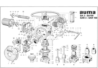
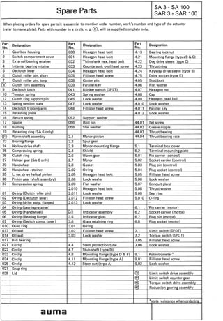
SA 3 - SA 100
SAR 3 - SAR 100
"
63](https://image.slidesharecdn.com/cwbutterflyvalve-180807095211/85/Cw-butterfly-valve-7-320.jpg)
![I
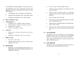
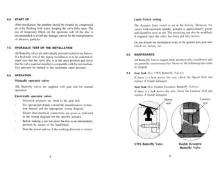
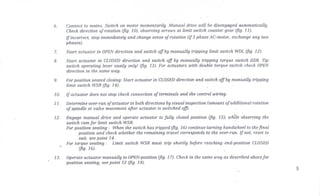
All auma actuators are 100% tested andfactory checked. Actuators are supplied readyjOr seroice. Most of the actua-
tors are supplied to valve manufacturers for mounting to valves. It is usual for the valve manufacturer to set the
switchef and test the motorisea valve.
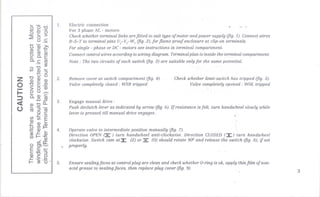
Special care should be taken when commissioning. Wrong connection or faulty control wiring may result in
damage to the motorised valve.
1n case the actuators will not be mounted or commissioned for a long period, take carefor adequate (dry) stotClfle.
refer to our instruction sheet "Transport. StorClfleand Commissionirlf} of auma-actuators".
'"
auma [india] pvt Itd
Plot No. 39-B, IIPhase
Peenya Industrial Area
Bangalore - 560.058.
Telephone: 28394365-6, 28394655
Fax :28392809
E-Mail: info@auma.co.in DD/MN-001 ISSUE 3/05](https://image.slidesharecdn.com/cwbutterflyvalve-180807095211/85/Cw-butterfly-valve-19-320.jpg)


