Panasonic servo motor line up driver and motor combination
•
1 like•849 views

Panasonic servo motor line up driver and motor combination
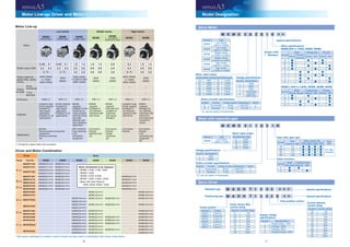
![12 13
Positive
direction
(CCW)
Negative
direction
(CW)
<Note>
回転方向の初期設定を
正方向(CCW)、負方向(CW)と
定義しています。
ご注意ください。
Overall Wiring
Setup support software “PANATERM”
Please download from our web site.
Regenerative resistor
(optional)
機種別のエンコーダケーブル
(別売:オプション)を用意しています。
DC Power supply
for brake DC24V
(to be supplied by customer)
フィードバックスケール等の
外部機器を接続します。
(A5E シリーズには X5 コネクタはありません)
上位コントローラとの通信等
(A5E シリーズには X2 コネクタはありません)
Connection to PC
USB mini-B cable
(市販品をご用意下さい)
主電源が入っている時に点灯します。
Controller
Junction cable
for brake
Junction cable
for brake
Junction cable for encoder
Connection to RS232,
RS485 or host controller
Connection to external scale
Connection to encoder
Connection to Monitor output
Digital/Analogue Monitor output Connection to Monitor output
Digital/Analogue Monitor output
Connection to input power
Wiring of Main Connector
Wiring of Main Connector
セーフティ回路を構築しない
場合に使用します。(標準装備)
(A5E シリーズには X3 コネクタはありません)
Connection to Safety
by-pass plug
50 ピンの入出力信号用
Connection to host controller
パラメータ、エラーの表示
7セグメントLED表示パネル
Charg lamp
Motor
Regenerative resistor
(optional)
Junction cable for brake
(optional)
Junction cable for brake
(optional)
ブレーキ有りモータの
場合のみ使用します。
[Connector type (A to E-frame)] [Connector type (D, E-frame 400V)]
Reactor (L)
Magnetic Contactor (MC)
Noise Filter (NF)
Circuit Breaker (MCCB)
(optional)
(optional)
Terminal block type
(F-frame)
Ground (earth)
<Caution>
製品の取り付けネジの締付トルクは使用されるネ
ジの強度、取り付け先の材質を考慮し、緩みや破
損の無い様に適切に選定してください。
例)鋼材への鋼材ネジ(M5)での
締付けの場合、2.7∼3.3N・m。
Mains
Residual
current device
Setup support software “PANATERM”
Please download from our web site.
機種別のエンコーダケーブル
(別売:オプション)を用意しています。
DC Power supply
for brake DC24V
(to be supplied by customer)
フィードバックスケール等の
外部機器を接続します。
(A5E シリーズには X5 コネクタはありません)
上位コントローラとの通信等
(A5E シリーズには X2 コネクタはありません)
Connection to PC
USB mini-B cable
(市販品をご用意下さい)
主電源が入っている時に
点灯します。
Controller
Junction cable for encoder
Connection to RS232,
RS485 or host controller
Connection to external scale
Connection to encoder
セーフティ回路を構築しない
場合に使用します。(標準装備)
(A5E シリーズには X3 コネクタはありません)
Connection to Safety
by-pass plug
50 ピンの入出力信号用
Connection to host controller
パラメータ、エラーの表示
7セグメントLED表示パネル
Charg lamp
Motor
ブレーキ有りモータの
場合のみ使用します。
Reactor (L)
Magnetic Contactor (MC)
Noise Filter (NF)
Circuit Breaker (MCCB)
Main
power
supply
Control
power
supply
(optional)
(optional)
Ground
(earth)
DC
power
(24V)
Mains
Residual
current
device](data:image/gif;base64,R0lGODlhAQABAIAAAAAAAP///yH5BAEAAAAALAAAAAABAAEAAAIBRAA7)
Recommended
More Related Content
What's hot
What's hot (11)
Similar to Panasonic servo motor line up driver and motor combination
Similar to Panasonic servo motor line up driver and motor combination (20)
More from steven qi
More from steven qi (16)
Recently uploaded
Recently uploaded (20)
Panasonic servo motor line up driver and motor combination
- 1. 10 11 Motor Line-up/ Driver and Motor CombinationMotor Line-up/ Driver and Motor Combination Model Designation Motor Line-up Motor Low inertia Middle inertia High inertia MSMD (Small type) MSME (Small type) MSME (Large type) MDME MGME Low speed/ (High torque type) MHMD MHME Rated output (kW) 0.05 0.1 0.2 0.4 0.75 0.05 0.1 0.2 0.4 0.75 1.0 1.5 2.0 3.0 4.0 5.0 1.0 1.5 2.0 3.0 4.0 5.0 0.9 2.0 3.0 0.2 0.4 0.75 1.0 1.5 2.0 3.0 4.0 5.0 Rated rotational speed (Max. speed) (r/min) 3000 (5000) For 750W 3000 (4500) 3000 (6000) 3000 (5000) For 4.0kW and 5.0kW 3000 (4500) 2000 (3000) 1000 (2000) 3000 (5000) For 750W 3000 (4500) 2000 (3000) Rotary encoder 20-bit incremental ○ ○ ○ ○ ○ ○ ○ 17-bit absolute ○ ○ ○ ○ ○ ○ ○ Enclosure IP65 (*) IP67 (*) IP67 (*) IP67 (*) IP67 (*) IP65 (*) IP67 (*) Features • Leadwire type • Small capacity • Suitable for high speed application • Suitable for all applications • Small capacity • Suitable for high speed application • Suitable for all applications • Middle capacity • Suitable for the machines di- rectly coupled with ball screw and high stiffness and high repetitive application • Middle capacity • Suitable for low stiffness machines with belt driven • Middle capacity • Flat type and suitable for machines with space limitation • Leadwire type • Small capacity • Suitable for low stiffness machines with belt driven • Middle capacity • Suitable for low stiffness machines with belt driven, and large load moment of inertia Applications • Bonder • Semiconductor production equipment • Packing machines etc • SMT machines • Food machines • LCD production equipment • Conveyors • Robots • Machine tool etc • Conveyors • Robots • Textile machines etc • Conveyors • Robots • Conveyors • Robots • LCD manufacturing equipment etc (*) Except for output shaft, and connector. Driver and Motor Combination Driver Motor Frame Part No. MSMD MSME MSME MDME MGME MHMD MHME A-Frame MADHT1105 MSMD5AZ*** MSME5AZ*** MADHT1107 MSMD011*** MSME011*** MADHT1505 MSMD5AZ*** MSME5AZ*** MSMD012*** MSME012*** MADHT1507 MSMD022*** MSME022*** MHMD022*** B-Frame MBDHT2110 MSMD021*** MSME021*** MHMD021*** MBDHT2510 MSMD042*** MSME042*** MHMD042*** C-Frame MCDHT3120 MSMD041*** MSME041*** MHMD041*** MCDHT3520 MSMD082*** MSME082*** MHMD082*** D-Frame MDDHT3530 MDME102*** MHME102*** MDDHT2412 MDME104*** MHME104*** MDDHT5540 MSME102*** MDME152*** MGME092*** MHME152*** MSME152*** MDDHT3420 MSME104*** MDME154*** MGME094*** MHME154*** MSME154*** E-Frame MEDHT7364 MSME202*** MDME202*** MHME202*** MEDHT4430 MSME204*** MDME204*** MHME204*** F-Frame MFDHTA390 MSME302*** MDME302*** MGME202*** MHME302*** MFDHT5440 MSME304*** MDME304*** MGME204*** MHME304*** MFDHTB3A2 MSME402*** MDME402*** MGME302*** MHME402*** MSME502*** MDME502*** MHME502*** MFDHTA464 MSME404*** MDME404*** MGME304*** MHME404*** MSME504*** MDME504*** MHME504*** * A5E series (dedicated for position control) drivers are also used in combination with motors show above. Motor (Scheduled to be released.) • MDME 7.5kW, 11kW, 15kW • MHME 7.5kW • MGME 4.5kW, 6.0kW • MFME 1.5kW, 2.5kW, 4.5kW • Motor with Gear Reduce: 100W, 200W, 400W, 750W Servo Motor Motor with reduction gear Servo Driver M S M E 5 A Z G 1 S * * Motor rated output Symbol Rated output Symbol Rated output 5A 50W 10 1.0kW 01 100W 15 1.5kW 02 200W 20 2.0kW 04 400W 30 3.0kW 08 750W 40 4.0kW 09 0.9kW 50 5.0kW Special specifications Motor specifications MSME(50W to 750W), MSMD, MHMD Symbol Shaft Holding brake Oil seal Round Key-way, center tap without with without with A ● ● ● B ● ● ● C ● ● ● D ● ● ● S ● ● ● T ● ● ● U ● ● ● V ● ● ● MSME(1.0kW to 5.0kW), MDME, MGME, MHME Symbol Shaft Holding brake Oil seal Round Key-way without with without with C ● ● ● D ● ● ● G ● ● ● H ● ● ● Rotary encoder specifications Symbol Format Pulse counts Resolution Wires G Incremental 20-bit 1,048,576 5 S Absolute 17-bit 131,072 7 * S: can be used in incremental. Design order 1 : Standard Symbol Type MSME Low inertia (50W to 750W) Motor rated output Symbol Rated output 01 100W 02 200W 04 400W 08 750W Voltage specifications Symbol Specifications 1 100V 2 200V Gear ratio, gear type Symbol Gear reduction ratio Motor output (W) Gear type100 200 400 750 1N 1/5 ● ● ● ● For high accuracy 2N 1/9 ● ● ● ● 3N 1/15 ● ● ● ● 4N 1/25 ● ● ● ● Motor structure Symbol Shaft Holding brake Key-way without with 3 ● ● 4 ● ● Rotary encoder specifications Symbol Format Pulse counts Resolution Wires G Incremental 20-bit 1,048,576 5 S Absolute 17-bit 131,072 7 * S: can be used in incremental. Voltage specifications Symbol Specifications 1 100V 2 200V 4 400V Z 100V/200V common (50W only) M S M E 0 1 1 G 3 1 N Frame symbol Symbol Frame MADH Frame A MBDH Frame B MCDH Frame C MDDH Frame D MEDH Frame E MFDH Frame F Power device Max. current rating Symbol Current rating T1 10A T2 15A T3 30A T4 35A T5 50A T7 75A TA 100A TB 150A Supply voltage specifications Symbol Specifications 1 Single phase, 100V 3 3-phase, 200V 4 3-phase, 400V 5 Single/3-phase, 200V Current detector current rating Symbol Current rating 05 5A 07 7.5A 10 10A 12 12A 20 20A 30 30A 40 40A 64 64A 90 90A A2 120A Special specifications Special specifications Only position control Standard type M A D H T 1 5 0 5 * * * Positioning type M A D H T 1 5 0 5 E * * Symbol Type MSMD Low inertia (50W to 750W) MSME Low inertia (50W to 5.0kW) MDME Middle inertia (1.0kW to 5.0kW) MGME Middle inertia (0.9kW to 3.0kW) MHMD High inertia (200W to 750W) MHME High inertia (1.0kW to 5.0kW)
- 2. 12 13 Positive direction (CCW) Negative direction (CW) <Note> 回転方向の初期設定を 正方向(CCW)、負方向(CW)と 定義しています。 ご注意ください。 Overall Wiring Setup support software “PANATERM” Please download from our web site. Regenerative resistor (optional) 機種別のエンコーダケーブル (別売:オプション)を用意しています。 DC Power supply for brake DC24V (to be supplied by customer) フィードバックスケール等の 外部機器を接続します。 (A5E シリーズには X5 コネクタはありません) 上位コントローラとの通信等 (A5E シリーズには X2 コネクタはありません) Connection to PC USB mini-B cable (市販品をご用意下さい) 主電源が入っている時に点灯します。 Controller Junction cable for brake Junction cable for brake Junction cable for encoder Connection to RS232, RS485 or host controller Connection to external scale Connection to encoder Connection to Monitor output Digital/Analogue Monitor output Connection to Monitor output Digital/Analogue Monitor output Connection to input power Wiring of Main Connector Wiring of Main Connector セーフティ回路を構築しない 場合に使用します。(標準装備) (A5E シリーズには X3 コネクタはありません) Connection to Safety by-pass plug 50 ピンの入出力信号用 Connection to host controller パラメータ、エラーの表示 7セグメントLED表示パネル Charg lamp Motor Regenerative resistor (optional) Junction cable for brake (optional) Junction cable for brake (optional) ブレーキ有りモータの 場合のみ使用します。 [Connector type (A to E-frame)] [Connector type (D, E-frame 400V)] Reactor (L) Magnetic Contactor (MC) Noise Filter (NF) Circuit Breaker (MCCB) (optional) (optional) Terminal block type (F-frame) Ground (earth) <Caution> 製品の取り付けネジの締付トルクは使用されるネ ジの強度、取り付け先の材質を考慮し、緩みや破 損の無い様に適切に選定してください。 例)鋼材への鋼材ネジ(M5)での 締付けの場合、2.7∼3.3N・m。 Mains Residual current device Setup support software “PANATERM” Please download from our web site. 機種別のエンコーダケーブル (別売:オプション)を用意しています。 DC Power supply for brake DC24V (to be supplied by customer) フィードバックスケール等の 外部機器を接続します。 (A5E シリーズには X5 コネクタはありません) 上位コントローラとの通信等 (A5E シリーズには X2 コネクタはありません) Connection to PC USB mini-B cable (市販品をご用意下さい) 主電源が入っている時に 点灯します。 Controller Junction cable for encoder Connection to RS232, RS485 or host controller Connection to external scale Connection to encoder セーフティ回路を構築しない 場合に使用します。(標準装備) (A5E シリーズには X3 コネクタはありません) Connection to Safety by-pass plug 50 ピンの入出力信号用 Connection to host controller パラメータ、エラーの表示 7セグメントLED表示パネル Charg lamp Motor ブレーキ有りモータの 場合のみ使用します。 Reactor (L) Magnetic Contactor (MC) Noise Filter (NF) Circuit Breaker (MCCB) Main power supply Control power supply (optional) (optional) Ground (earth) DC power (24V) Mains Residual current device
- 3. 14 15 Driver and List of Applicable Peripheral Equipments Driver Applicable motor Voltage Rated output Required Power at the (rated load) Circuit breaker rated (current) Surge absorber Noise filter for signal Magnetic contactor 定格通電電流 (/開放熱電流) Cable diameter main (circuit) Cable diameter control (circuit ) Connection MADH MSMD MSME MHMD Single phase, 100V 50W to 100W approx. 0.4kVA 10A DV0P4190 DV0P1460 20A 0.75mm2 / AWG18 to 2.0mm2 / AWG14 0.75mm2 / AWG18 Connectiontoexclusiveconnector Single/3-phase, 200V 50W to 200W approx. 0.5kVA DV0P4190 / DV0P1450 MBDH MSMD MSME MHMD Single phase, 100V 200W approx. 0.5kVA DV0P4190 Single/3-phase, 200V 400W approx. 0.9kVA DV0P4190 / DV0P1450 MCDH MSMD MSME MHMD Single phase, 100V 400W approx. 0.9kVA DV0P4190 Single/3-phase, 200V 750W approx. 1.3kVA 15A DV0P4190 / DV0P1450 MDDH MDME Single/3-phase, 200V 1.0kW approx. 1.8kVA 30A 2.0mm2 / AWG14 MHME MGME 900W approx. 1.8kVA 20A MSME 1.0kW approx. 1.8kVA MHME 1.5kW approx. 2.3kVA MDME MSME MSME 3-phase, 400V 1.0kW approx. 1.8kVA 10A DV0PM20050 20A 0.5mm2 / AWG 20〜24 MDME MHME MGME 0.9kW MSME 1.5kW approx. 2.3kVA MDME MHME MEDH MDME MSME MHME 3-phase, 200V 2.0kW approx. 3.3kVA 30A DV0P1450 60A 0.75mm2 / AWG18 MSME MDME MHME 3-phase, 400V 2.0kW approx. 3.3kVA 15A DV0PM20050 30A 0.5mm2 / AWG 20〜24 MFDH MGME 3-phase, 200V 2.0kW approx. 3.8kVA 50A DV0P1450 60A 3.5mm2 / AWG12 0.75mm2 / AWG18 11mm or smaller φ5.3 Terminal block M5 MDME 3.0kW approx. 4.5kVA MHME MSME MGME MDME 4.0kW approx. 6kVA 100A MHME MSME MDME 5.0kW approx. 7.5kVA 5.3mm2 / AWG10 MHME MSME MGME 3-phase, 400V 2.0kW approx. 3.8kVA 30A DV0PM20050 60A 3.5mm2 / AWG12 MSME 3.0kW approx. 4.5kVA MDME MGME MHME MSME 4.0kW approx. 6.8kVA MDME MHME MSME 5.0kW approx. 7.5kVA MDME MHME • Select peripheral equipments for single/3phase common specification according to the power source. • About circuit breaker and magnetic contactor To comply to EC Directives, install a circuit breaker between the power and the noise filter without fail, and the circuit breaker should conform to IEC Standards and UL recognized (Listed and marked). Suitable for use on a circuit capable of delivering not more than 5,000 rms symmetrical amperes, be- low the maximum input voltage of the product. If the short-circuit current of the power supply exceeds this value, install a current limit device (current limiting fuse, current limiting circuit breaker, transformer, etc.) to limit the short-circuit current. <Remarks> • Select a circuit breaker and noise filter which match to the capacity of power supply (including a load condition). • Terminal block and protective earth terminals Use a copper conductor cables with temperature rating of 75˚C or higher. The screws of protective earth terminals for Frame A to D are M4 (Fastening torque: 0.7 to 0.8N·m) and M5 (Fastening torque: 1.4 to 1.6N·m) for Frame E, F. Fastening torque of earth screws. Tighten the terminal block screw on frame F with a torque between 1.0 and 2.0 N·m. Application of overtorque (more than 2.0 N·m) will cause damage to terminal block. Maximum allowable torque to the screw securing terminal block cover is 0.19 to 0.21 N·m. • The cable diameter of an earth cable. Use an earth cable with the same diameter or larger as that of the main circuit cable. If the diameter of the main circuit cable is 1.6mm2 or less, use an earth cable with a diameter of 2.0mm2 (AWG14). • Use the attached exclusive connector for A to E-frame, and maintain the peeled off length of 8 to 9mm. • Tighten the screws of the connector, Connector X4 for the host controller with the torque of 0.3 to 0.35 N·m. Larger torque than 0.35N·m may damage the connector at the driver side. <Caution> Do not turn on power without tightening all terminal block screws properly, otherwise, loose contacts may generate heat (smoking, firing).
- 4. Motor Driver Power capacity (atrated load) Optional parts Motor series Power supply Output (W) Part No. Note) 1 Rating/ Spec. (page) Part No. (Standard type) Part No. (Positioning type) Frame Encoder cable Motor cable Brake cable Note) 2 Regenerative resistor Reactor Noise filter 20-bit Incremental Note) 2 17-bit Absolute Note) 2 without brake Note) 2 with brake Note) 2 16 17 MotorOptionsInformation Table of Part Numbers and Options Table of Part Numbers and Options Driver note)1 Rotary encoder specifications: □ Motor specification: * (refer to P.13) note)2 Cable length: ** (03: 3m, 05: 5m, 10: 10m, 20: 20m) • Options Title 構成品名 Part No. Page Interface cable DV0P4360 118 Interface Connector DV0P4350 118 Connector for Power Supply Input Connection A to D-frame 100V/ (200V ) Single row type DV0PM20032 120 Double row type DV0PM20033 120 E-frame (200V) DV0PM20044 120 D-frame (400V) DV0PM20051 121 E-frame (400V) DV0PM20052 121 Connector for Control Power Supply Input Connection D, E-frame (400V) DV0PM20053 121 Connector for Motor Connection A to D-frame DV0PM20034 121 E-frame (200V) DV0PM20046 122 D-frame (400V) DV0PM20054 122 Connector for Regenerative Resistor E-frame DV0PM20045 121 D-frame (400V) DV0PM20055 121 Connector Kit for Motor/Encoder Connection DV0P4290 122 DV0P4380 122 DV0PM20035 123 DV0PM20036 123 DV0PM20037 123 DV0PM20038 124 DV0PM20039 124 Connector Kit for Motor/Brake Connection DV0PM20040 124 Connector RS485, RS232 DV0PM20024 119 Safety DV0PM20025 119 External Scale DV0PM20026 119 Encoder DV0PM20010 119 Analog Monitor Signal DV0PM20031 120 Battery For Absolute Encoder DV0P2990 125 Battery Box DV0P4430 125 Mounting bracket A-frame DV0PM20027 126 B-frame DV0PM20028 126 C-frame DV0PM20029 126 D-frame DV0PM20030 126 Junction Cable for Encoder without Buttery Box MFECA0**0EAM 112 MFECA0**0MJD 112 MFECA0**0ETD 113 with Buttery Box MFECA0**0EAE 112 MFECA0**0MJE 113 MFECA0**0ETE 113 Junction Cable for Motor without Brake MFMCA0**0EED 114 MFMCA0**0NJD 114 MFMCD0**2ECD 114 MFMCE0**2ECD 115 MFMCA0**3ECT 115 with Brake MFMCA0**2FCD 116 MFMCE0**2FCD 116 MFMCA0**3FCT 116 Junction Cable for Brake MFMCB0**0GET 117 MFMCB0**0PJT 117 External Regenerative Resistor 50Ω 25W DV0P4280 128 100Ω 25W DV0P4281 128 25Ω 50W DV0P4282 128 50Ω 50W DV0P4283 128 30Ω 100W DV0P4284 128 20Ω 130W DV0P4285 128 120Ω 35W DV0PM20048 128 80Ω 65W DV0PM20049 128 Reactor DV0P220, DV0P221, DV0P222, DV0P223, DV0P224, DV0P225, DV0P227, DV0P228 127 Noise Filter DV0P4170, DV0PM20042 DV0P4220, DV0PM20043 DV0P3410 108 Surge absorber Single phase DV0P4190 109 3-phase (200V) DV0P1450 109 3-phase (400V) DV0PM20050 109 Noise Filter for Signal Lines DV0P1460 109 Motor Driver Power capacity (atrated load) Optional parts Motor series Power supply Output (W) Part No. Note) 1 Rating/ Spec. (page) Part No. (Standard type) Part No. (Positioning type) Frame Encoder cable Motor cable Brake cable Note) 2 Regenerative resistor Reactor Noise filter 20-bit Incremental Note) 2 17-bit Absolute Note) 2 without brake Note) 2 with brake Note) 2 Lowinertia MSMD Leadwire ( type ) 3000r/min Single phase 100V 50 MSMD5AZ□1* 66 MADHT1105 MADHT1105E A-frame Approx. 0.4kVA MFECA 0**0EAM MFECA 0**0EAE MFMCA 0**0EED — MFMCB 0**0GET DV0P4280 DV0P227 DV0P4170100 MSMD011□1* 68 MADHT1107 MADHT1107E Approx. 0.4kVA 200 MSMD021□1* 70 MBDHT2110 MBDHT2110E B-frame Approx. 0.5kVA DV0P4283 DV0P228 400 MSMD041□1* 72 MCDHT3120 MCDHT3120E C-frame Approx. 0.9kVA DV0P4282 DV0PM20042 Single phase/ 3-phase 200V 50 MSMD5AZ□1* 67 MADHT1505 MADHT1505E A-frame Approx. 0.5kVA DV0P4281 DV0P220 DV0PM20042 100 MSMD012□1* 69 MADHT1505 MADHT1505E Approx. 0.5kVA 200 MSMD022□1* 71 MADHT1507 MADHT1507E Approx. 0.5kVA DV0P4283400 MSMD042□1* 73 MBDHT2510 MBDHT2510E B-frame Approx. 0.9kVA DV0P221 750 MSMD082□1* 74 MCDHT3520 MCDHT3520E C-frame Approx. 1.3kVA MSME 3000r/min Single phase 100V 50 MSME5AZ□1* 36 MADHT1105 MADHT1105E A-frame Approx. 0.4kVA MFECA 0**0MJD MFECA 0**0MJE MFMCA 0**0NJD — MFMCB 0**0PJT DV0P4280 DV0P227 DV0P4170100 MSME011□1* 38 MADHT1107 MADHT1107E Approx. 0.4kVA 200 MSME021□1* 40 MBDHT2110 MBDHT2110E B-frame Approx. 0.5kVA DV0P4283 DV0P228 400 MSME041□1* 42 MCDHT3120 MCDHT3120E C-frame Approx. 0.9kVA DV0P4282 DV0PM20042 Single phase/ 3-phase 200V 50 MSME5AZ□1* 37 MADHT1505 MADHT1505E A-frame Approx. 0.5kVA DV0P4281 DV0P220 DV0PM20042 100 MSME012□1* 39 MADHT1505 MADHT1505E Approx. 0.5kVA 200 MSME022□1* 41 MADHT1507 MADHT1507E Approx. 0.5kVA DV0P4283400 MSME042□1* 43 MBDHT2510 MBDHT2510E B-frame Approx. 0.9kVA DV0P221 750 MSME082□1* 44 MCDHT3520 MCDHT3520E C-frame Approx. 1.3kVA MSME 3000r/min Single phase/ 3-phase 200V 1000 MSME102□1* 45 MDDHT5540 MDDHT5540E D-frame Approx. 1.8kVA MFECA 0**0ETD MFECA 0**0ETE MFMCD 0**2ECD MFMCA 0**2FCD — DV0P4284 DV0P222 DV0P4220 1500 MSME152□1* 46 MDDHT5540 MDDHT5540E Approx. 2.3kVA 3-phase 200V 2000 MSME202□1* 47 MEDHT7364 MEDHT7364E E-frame Approx. 3.3kVA DV0P4285 DV0P223 DV0PM20043 3000 MSME302□1* 48 MFDHTA390 MFDHTA390E F-frame Approx. 4.5kVA MFMCA 0**3ECT MFMCA 0**3FCT DV0P4285 × 2 in parallel DV0P224 DV0P34104000 MSME402□1* 49 MFDHTB3A2 MFDHTB3A2E Approx. 6kVA DV0P225 5000 MSME502□1* 50 MFDHTB3A2 MFDHTB3A2E Approx. 7.5kVA — 3-phase 400V 1000 MSME104□1* 82 MDDHT3420 MDDHT3420E D-frame Approx. 1.8kVA MFMCD 0**2ECD MFMCE 0**2FCD DV0PM20048 — — 1500 MSME154□1* 83 MDDHT3420 MDDHT3420E Approx. 2.3kVA 2000 MSME204□1* 84 MEDHT4430 MEDHT4430E E-frame Approx. 3.3kVA DV0PM20049 3000 MSME304□1* 85 MFDHT5440 MFDHT5440E F-frame Approx. 4.5kVA MFMCA 0**3ECT MFMCA 0**3FCT DV0PM20049 × 2 in parallel 4000 MSME404□1* 86 MFDHTA464 MFDHTA464E Approx. 6.8kVA 5000 MSME504□1* 87 MFDHTA464 MFDHTA464E Approx. 7.5kVA Middleinertia MDME 2000r/min Single phase/ 3-phase 200V 1000 MDME102□1* 51 MDDHT3530 MDDHT3530E D-frame Approx. 1.8kVA MFECA 0**0ETD MFECA 0**0ETE MFMCD 0**2ECD MFMCA 0**2FCD — DV0P4284 DV0P222 DV0P4220 1500 MDME152□1* 52 MDDHT5540 MDDHT5540E Approx. 2.3kVA 3-phase 200V 2000 MDME202□1* 53 MEDHT7364 MEDHT7364E E-frame Approx. 3.3kVA DV0P4285 DV0P223 DV0PM20043 3000 MDME302□1* 54 MFDHTA390 MFDHTA390E F-frame Approx. 4.5kVA MFMCA 0**3ECT MFMCA 0**3FCT DV0P4285 × 2 in parallel DV0P224 DV0P34104000 MDME402□1* 55 MFDHTB3A2 MFDHTB3A2E Approx. 6kVA DV0P225 5000 MDME502□1* 56 MFDHTB3A2 MFDHTB3A2E Approx. 7.5kVA — 3-phase 400V 1000 MDME104□1* 88 MDDHT2412 MDDHT2412E D-frame Approx. 1.8kVA MFMCD 0**2ECD MFMCE 0**2FCD DV0PM20048 — — 1500 MDME154□1* 89 MDDHT3420 MDDHT3420E Approx. 2.3kVA 2000 MDME204□1* 90 MEDHT4430 MEDHT4430E E-frame Approx. 3.3kVA DV0PM20049 3000 MDME304□1* 91 MFDHT5440 MFDHT5440E F-frame Approx. 4.5kVA MFMCA 0**3ECT MFMCA 0**3FCT DV0PM20049 × 2 in parallel 4000 MDME404□1* 92 MFDHTA464 MFDHTA464E Approx. 6.8kVA 5000 MDME504□1* 93 MFDHTA464 MFDHTA464E Approx. 7.5kVA MGME 1000r/min Single phase/ 3-phase 200V 900 MGME092□1* 57 MDDHT5540 MDDHT5540E D-frame Approx. 1.8kVA MFECA 0**0ETD MFECA 0**0ETE MFMCD0**2ECD MFMCA0**2FCD — DV0P4284 DV0P222 DV0P4220 3-phase 200V 2000 MGME202□1* 58 MFDHTA390 MFDHTA390E F-frame Approx. 3.8kVA MFMCA 0**3ECT MFMCA 0**3FCT DV0P4285 × 2 in parallel DV0P223 DV0P3410 3000 MGME302□1* 59 MFDHTB3A2 MFDHTB3A2E Approx. 4.5kVA DV0P224 3-phase 400V 900 MGME094□1* 94 MDDHT3420 MDDHT3420E D-frame Approx. 1.8kVA MFMCD0**2ECD MFMCE0**2FCD DV0PM20048 — —2000 MGME204□1* 95 MFDHT5440 MFDHT5440E F-frame Approx. 3.8kVA MFMCA 0**3ECT MFMCA 0**3FCT DV0PM20049 × 2 in parallel3000 MGME304□1* 96 MFDHTA464 MFDHTA464E Approx. 4.5kVA Highinertia MHMD Leadwire ( type ) 3000r/min Single phase 100V 200 MHMD021□1* 76 MBDHT2110 MBDHT2110E B-frame Approx. 0.5kVA MFECA 0**0EAM MFECA 0**0EAE MFMCA 0**0EED — MFMCB 0**0GET DV0P4283 DV0P228 DV0P4170 400 MHMD041□1* 78 MCDHT3120 MCDHT3120E C-frame Approx. 0.9kVA DV0P4282 DV0PM20042 Single phase/ 3-phase 200V 200 MHMD022□1* 77 MADHT1507 MADHT1507E A-frame Approx. 0.5kVA DV0P4283 DV0P220 DV0PM20042400 MHMD042□1* 79 MBDHT2510 MBDHT2510E B-frame Approx. 0.9kVA DV0P221 750 MHMD082□1* 80 MCDHT3520 MCDHT3520E C-frame Approx. 1.3kVA MHME 2000r/min Single phase/ 3-phase 200V 1000 MHME102□1* 60 MDDHT3530 MDDHT3530E D-frame Approx. 1.8kVA MFECA 0**0ETD MFECA 0**0ETE MFMCD 0**2ECD MFMCA 0**2FCD — DV0P4284 DV0P222 DV0P4220 1500 MHME152□1* 61 MDDHT5540 MDDHT5540E Approx. 2.3kVA 3-phase 200V 2000 MHME202□1* 62 MEDHT7364 MEDHT7364E E-frame Approx. 3.3kVA MFMCE0**2ECD MFMCE0**2FCD DV0P4285 DV0P223 DV0PM20043 3000 MHME302□1* 63 MFDHTA390 MFDHTA390E F-frame Approx. 4.5kVA MFMCA 0**3ECT MFMCA 0**3FCT DV0P4285 × 2 in parallel DV0P224 DV0P34104000 MHME402□1* 64 MFDHTB3A2 MFDHTB3A2E Approx. 6kVA DV0P225 5000 MHME502□1* 65 MFDHTB3A2 MFDHTB3A2E Approx. 7.5kVA — 3-phase 400V 1000 MHME104□1* 98 MDDHT2412 MDDHT2412E D-frame Approx. 1.8kVA MFMCD 0**2ECD MFMCE 0**2FCD DV0PM20048 — — 1500 MHME154□1* 99 MDDHT3420 MDDHT3420E Approx. 2.3kVA 2000 MHME204□1* 100 MEDHT4430 MEDHT4430E E-frame Approx. 3.3kVA MFMCE0**2ECD DV0PM20048 3000 MHME304□1* 101 MFDHT5440 MFDHT5440E F-frame Approx. 4.5kVA MFMCA 0**3ECT MFMCA 0**3FCT DV0PM20049 × 2 in parallel 4000 MHME404□1* 102 MFDHTA464 MFDHTA464E Approx. 6.8kVA 5000 MHME504□1* 103 MFDHTA464 MFDHTA464E Approx. 7.5kVA